Embed Size (px)
Citation preview

Solid State Morphing Aircraft Team
Progress Report 02/13/2014
Members:James BirdRoger BounthisaneAmber CookElaine GumapasThoai NguyenJeremiah Silvis

Aerodynamics
Wandering Albatross
Common Buzzard
Grey Heron
Cormorant

Geometric Shapes
Rounded Rectangle (Buzzard)
Most simple fabrication shape and theoretical analysis
Elliptic (Grey heron)
Least amount of induced drag
Pointed Tip (Wandering Albatross)
Generates the most lift
Dihedral (Cormorant)
Flies at higher speeds

Length(m)
Sheets (#)
Total Thickness (m)
Harmonic Freq.
0.75 1 0.00085 3.500.75 2 0.00170 7.000.75 3 0.00300 12.360.85 1 0.00085 2.730.85 2 0.00170 5.450.85 3 0.00300 9.620.90 1 0.00085 2.430.90 2 0.00170 4.860.90 3 0.00300 8.581.00 1 0.00085 1.971.00 2 0.00170 3.941.00 3 0.00300 6.951.10 1 0.00085 1.631.10 2 0.00170 3.261.10 3 0.00300 5.75
EDensity (kg/m^3)
Thickness(m)
CF5.12E+
09 1010.87 0.000085
Wing Span(m)
Chord Length (m)
Leading Edge
Trailing Edge
Thickness (m)
Volume (m^3)
Mass (kg) lb
1.5 0.5 Straight Elliptic 8.50E-05 5.01E-04 0.506 1.113
1.5 0.5 straightrounded
rect 8.50E-05 6.21E-04 0.628 1.381
1.5 0.3 Straighttriangle
edge 8.50E-05 2.61E-04 0.264 0.5811.5 0.75 Straight pointed tip 8.50E-05 5.76E-04 0.582 1.280
Wing Characteristics
Wing Natural Freq.
𝑊 𝑛=√ 𝑘𝑚𝑒
𝑘=3𝐸𝐼𝑙3
𝑚𝑒= 33140
𝑚𝑤𝑖𝑛𝑔+𝑚𝑡𝑖𝑝𝑚𝑎𝑠𝑠
𝑚𝑤𝑖𝑛𝑔=𝜌 𝑙𝑡𝑑
𝐼𝑟𝑒𝑐𝑡=𝑏h3
12
𝑊𝑛2=
3𝐸𝑑𝑡3
12 𝑙3
33140
𝜌 𝑙𝑡𝑑
𝑊𝑛=√ 35𝐸 𝑑2
33𝜌 𝑙4

Structural
Projected Weight
ItemWeight (oz.)
Mass (g)
DC-DC Converter 0.98 27.78
11.1 V Battery5.96
169.00
Half-size breadboard 1.27 36.00Microcontroller 0.23 6.50
fuzelage 3.60102.0
6
Wing 12.00506.0
0
Total 24.04847.3
4=1.86 lb.

Finite Element Model
0.5 1 1.5 2 2.5 3 3.5 4 4.5 5 5.50
5
10
15
20
25
30
35
40
45
f(x) = 41.4489865273179 x^-2.91954850887085R² = 0.999422649096742
Number of Layers Vs. Deflection
Number of Layers
Deflect
ion
0.5 1 1.5 2 2.5 3 3.5 4 4.5 5 5.50
10
20
30
40
50
60
f(x) = 10.5 x + 0.192666666666668R² = 0.999390844463689
Number of Layers Vs. Natural Frequency
Number of layers
Naatu
ral Fr
equency
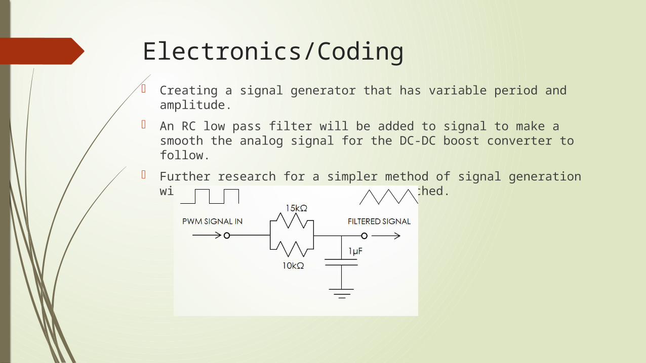
Electronics/Coding Creating a signal generator that has variable period and amplitude.
An RC low pass filter will be added to signal to make a smooth the analog signal for the DC-DC boost converter to follow.
Further research for a simpler method of signal generation with analog control is being researched.

Arduino Code sketch_jan31.ino/* created by: James Bird last modified: 1/31/14 */
int diff, feedback, time;int dir=1;int count=1;int pos=1;int diffPot=0;int timePot=3;int feedbackPin=5;
void setup(){ pinMode(9,OUTPUT); Serial.begin(9600);}
void loop(){ diff=.1*analogRead(diffPot); //0.1*(1023)=MAX of 102 bit step time=.1*analogRead(timePot); //0.1*1023=MAX of 102 ms time delay feedback=analogRead(feedbackPin); pos=pos+dir*diff; //newPos=oldPos+(direction)step
if(pos<0) { dir=1; pos=0; } if(pos>255) { dir=-1; pos=255; } analogWrite(9,pos); delay(time);}

Output
Maximum Frequency : 12 HzVoltage ranges from 0 to 2.60 VDC
STEP
DELAY
PWM
A0
A3RC FILTER
A5
Oscilloscope
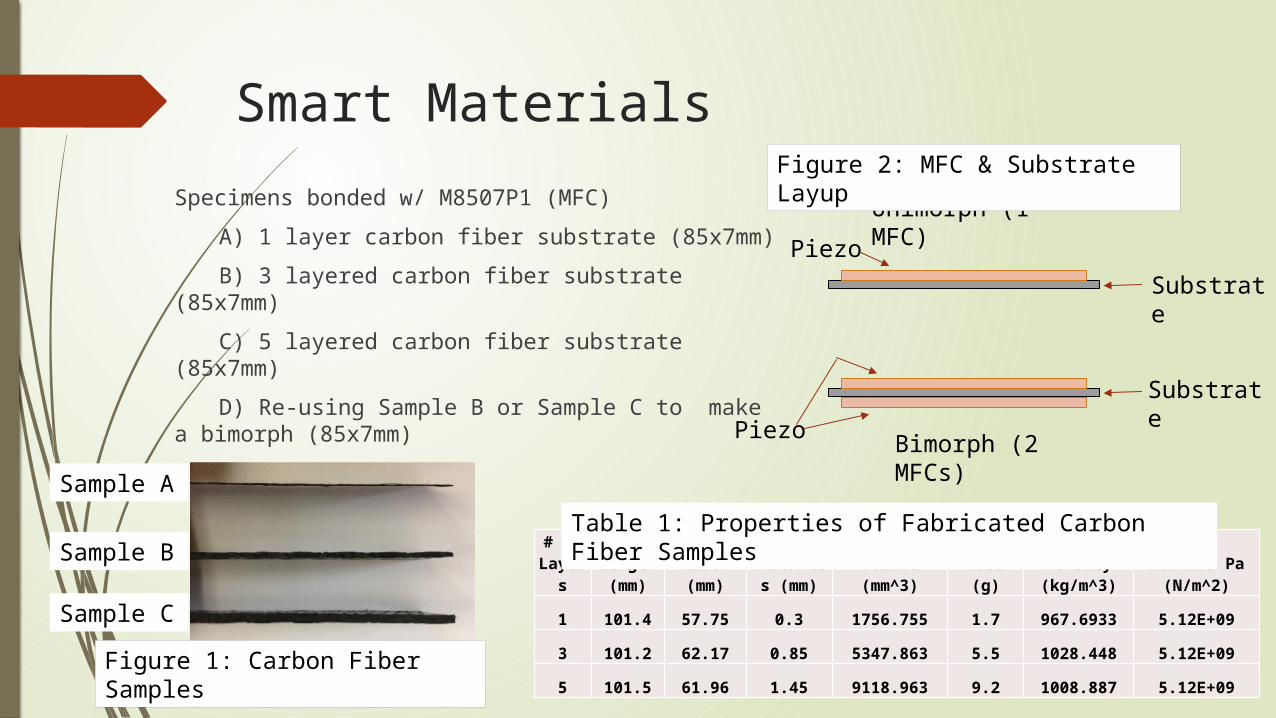
Specimens bonded w/ M8507P1 (MFC)
A) 1 layer carbon fiber substrate (85x7mm)
B) 3 layered carbon fiber substrate (85x7mm)
C) 5 layered carbon fiber substrate (85x7mm)
D) Re-using Sample B or Sample C to make a bimorph (85x7mm)
Unimorph (1 MFC)
Bimorph (2 MFCs)
Substrate
Substrate
Piezo
Piezo
Smart Materials
# of Layer
sLength (mm)
Width (mm)
Thickness (mm)
Volume (mm^3)
Mass (g)
Density (kg/m^3)
Modulus Pa (N/m^2)
1 101.4 57.75 0.3 1756.755 1.7 967.6933 5.12E+09
3 101.2 62.17 0.85 5347.863 5.5 1028.448 5.12E+09
5 101.5 61.96 1.45 9118.963 9.2 1008.887 5.12E+09
Table 1: Properties of Fabricated Carbon Fiber Samples
Sample A
Sample B
Sample C
Figure 1: Carbon Fiber Samples
Figure 2: MFC & Substrate Layup

Test runs are in progress of bonding the MFC to the carbon fiber substrate to prevent any imperfections or slippage while being vacuum bagged
Current Fabrication
Tape Hinges
Macro-Fiber Composite
Carbon Fiber SubstrateGlue Epoxy
Figure 3: MFC & Carbon Fiber
Figure 4: Component Layup

Apparatus similar to composite testing for
a fixed end cantilever beam
Samples will be tested through series of voltage loads from 0 to 1500v
Data collected and analyzed to observe the relationship between strain (having proportional relationship to voltage) and blocking force of the MFC
Figure 5: Apparatus Setup
Testing
Figure 6: Blocking Force Experiment