Embed Size (px)
Citation preview
N A T I O N A L A E R O N A U T I C S A N D S P A C E A D M I N I S T R A T I O N
Technical Memorandum 33- 534
Solid Propulsion Advanced Concepts
Y. Nakamura
J. I. Shafer
J E T P R O P U L S I O N L A B O R A T O R Y
C A L I F O R N I A I N S T I T U T E O F T E C H N O L O G Y
P A S A D E N A , C A L I F O R N I A
May 1 , 1972
https://ntrs.nasa.gov/search.jsp?R=19720017270 2020-04-25T21:05:47+00:00Z
Prepared Under Contract No. NAS 7-1 00 National Aeronautics and Space Administration
PREFACE
The work descr ibed in this report was performed by the Propuls ion
Division of the Jet Propuls ion Laboratory.
J P L Technical Memorandum 3 3 - 5 3 4 ... 111
ACKNOWLEDGEMENT
iv
The following J P L individuals provided major inputs and/or
guidelines in the i r respect ive a r e a s of specialty.
Support Area Name
Launch Vehicles
Spacecraft Des ign
Science Package
Solar Electr ic Propuls ion
Tra jec tory Analysis
Cost - Eff ec tivenes s As s es sment
Mission/Sys t ems Analys is
A. N. Williams
R. F. Draper
E. J. Smith M. M. Neugebauer
D. R. Bar tz J. W. S tearns , J r .
R. D. Bourke
R. L. Phen
R. J. Beale
The authors a r e a lso indebted to the P ioneer P ro jec t personnel a t the
Ames Research Center fo r the i r invaluable ass is tance. Special mention i s
made of C. F. Hall, R. U. Hofstetter, J. E. Lepetich, and J. D. Mihalov
for the i r views in the a r e a s of spin-stabil ized spacecraf t design, data
management techniques, and science package requi rements .
J P L Technical Memorandum 33- 534
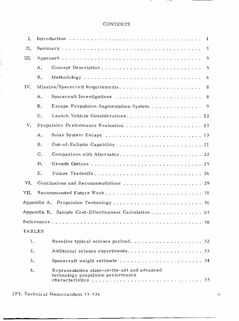
CONTENTS
I . Introduction . . . . . . . . . . . . . . . . . . . . . . . . . . . . . . . . . . . . . 1
I1 . Summary . . . . . . . . . . . . . . . . . . . . . . . . . . . . . . . . . . . . . . . 3
I11 . Approach . . . . . . . . . . . . . . . . . . . . . . . . . . . . . . . . . . . . . . . 5
~ A . Concept Description . . . . . . . . . . . . . . . . . . . . . . . . . . . . 5
I B . Methodology . . . . . . . . . . . . . . . . . . . . . . . . . . . . . . . . . 6
IV . Mis sion/Spacec raft Requirements . . . . . . . . . . . . . . . . . . . . . . . 8
A . Spacecraf t Investigations . . . . . . . . . . . . . . . . . . . . . . . . 8
B . Escape Propuls ion Augmentation Sys tem . . . . . . . . . . . . . . 9
C . Launch Vehicle Considerations . . . . . . . . . . . . . . . . . . . . . 1 2
V . Propuls ive Per formance Evaluation . . . . . . . . . . . . . . . . . . . . . 13
A . Solar System Escape . . . . . . . . . . . . . . . . . . . . . . . . . . . 13
B . Out-of-Ecliptic Capability . . . . . . . . . . . . . . . . . . . . . . . . 21
C . Comparison with Alternates . . . . . . . . . . . . . . . . . . . . . . . 2 2
D . Growth Options . . . . . . . . . . . . . . . . . . . . . . . . . . . . . . . 25
E . Future Tradeoffs . . . . . . . . . . . . . . . . . . . . . . . . . . . . . . 26
V I . Conclusions and Recommendations . . . . . . . . . . . . . . . . . . . . . . 29
VI1 . Recommended Future Work . . . . . . . . . . . . . . . . . . . . . . . . . . . 31
Appendix A . Propuls ion Technology . . . . . . . . . . . . . . . . . . . . . . . . . 56
Appendix B . Sample Co st-Effectivene ss Calculation . . . . . . . . . . . . . . 67
Refe rences . . . . . . . . . . . . . . . . . . . . . . . . . . . . . . . . . . . . . . . . . . 70
TABLES
1 . Baseline typical science payload . . . . . . . . . . . . . . . . . . . . 32
2 . Additional science experiments . . . . . . . . . . . . . . . . . . . . . 33
3 . Spacecraf t weight es t imate . . . . . . . . . . . . . . . . . . . . . . . 34
4 . Repr e sentative s ta te -of . the-ar t and advanced techno logy propulsion pe r fo r manc e cha rac t e r i s t i c s . . . . . . . . . . . . . . . . . . . . . . . . . . . . . . . 35
JPL Technical Memorandum 33-534 V
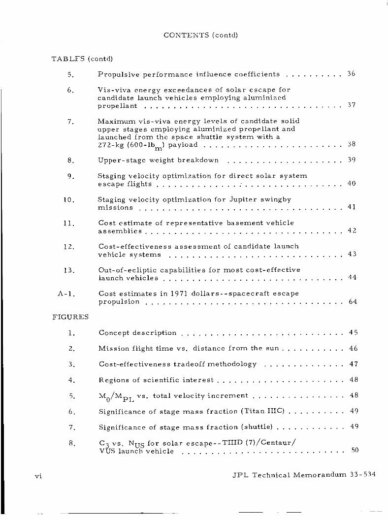
CONTENTS (contd)
TABLES (contd)
5. Propulsive pe r fo rmanc e inf h e nc e coefficients . . . . . . . . . . 3 6
6. Vis-viva energy exceedances of solar escape for candidate launch vehicles employing aluminized propellant . . . . . . . . . . . . . . . . . . . . . . . . . . . . . . . . . . 37
7. Maximum vis-viva energy levels of candidate solid upper s tages employing aluminized propellant and launched f r o m the space shuttle sys tem with a 272-kg (600-lbm) payload . . . . . . . . . . . . . . . . . . . . . . . . 38
Upper-stage weight breakdown . . . . . . . . . . . . . . . . . . . . 39 8.
9 . Staging velocity optimization for d i rec t solar sys tem escape flights . . . . . . . . . . . . . . : . . . . . . . . . . . . . . . . . 40
10. Staging velocity optimization for Jupiter swingby 41 miss ions . . . . . . . . . . . . . . . . . . . . . . . . . . . . . . . . . . .
11. Cost es t imate of representat ive basement vehicle assembl ies . . . . . . . . . . . . . . . . . . . . . . . . . . . . . . . . . . 42
12. Cost- effectivene s s a s s e s s m e n t of candidate launch vehicle sys tems . . . . . . . . . . . . . . . . . . . . . . . . . . . . . . 4 3
13. Out - of - ecliptic c apa bi lit ie s f o r m o s t c o s t - effective launch vehicles . . . . . . . . . . . . . . . . . . . . . . . . . . . . . . . 44
A-1. Cost es t imates i n 1971 dol la rs - - spacecraf t escape propulsion . . . . . . . . . . . . . . . . . . . . . . . . . . . . . . . . . . 64
FIGURES
1. Concept description . . . . . . . . . . . . . . . . . . . . . . . . . . . . 45
2. Mission flight t ime vs . distance f r o m the s u n . . . . . . . . . . . 46
3 . C o s t-ef f e c tive n e s s t r ade off methodology . . . . . . . . . . . . . . 4 7
4.
5.
6.
Regions of scientific i n t e r e s t . . . . . . . . . . . . . . . . . . . . . . 4% Mo/MpL vs. total velocity inc remen t . . . . . . . . . . . . . . . . 48
Significance of stage mass f rac t ion (Ti tan IIIC) . . . . . . . . . . 49
7.
8 .
Significance of stage mass fract ion (shuttle) . . . . . . . . . . . . C3 vs . NUS f o r so la r escape--TIIID (7)/Centaur/ VUS launch vehicle
49
. . . . . . . . . . . . . . . . . . . . . . . . . . . . 50
vi . J P L Technical Memorandum 33- 534
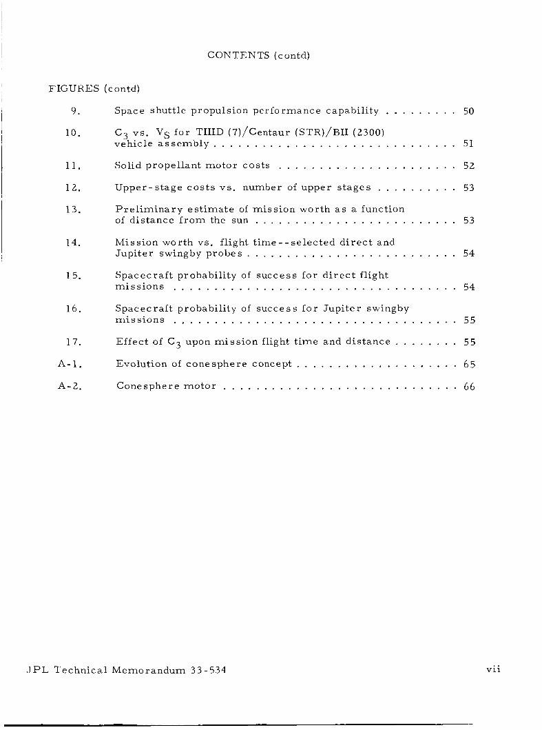
~ CONTENTS (contd)
I FIGURES (contd)
9 . Space shuttle propulsion performance capability . . . . . . . . . 50
C3 v s . VS for TIIID (7)/Centaur (STR)/BII (2300) vehicle a s sembly . . . . . . . . . . . . . . . . . . . . . . . . . . . . . . 51
10 .
11 . Solid propellant motor costs . . . . . . . . . . . . . . . . . . . . . . 52
12 . Upper-s tage cos t s v s . number of upper s tages . . . . . . . . . . 53
13 . Pre l imina ry es t imate of miss ion worth a s a function of distance f r o m the sun . . . . . . . . . . . . . . . . . . . . . . . . . 53
14 . Mission worth v s . flight t ime . . selected d i r ec t and Jupiter swingby probes . . . . . . . . . . . . . . . . . . . . . . . . . . 54
1 5 . Spacecraf t probability of success for d i r ec t flight mi s s ions . . . . . . . . . . . . . . . . . . . . . . . . . . . . . . . . . . . 54
16 . Spacecraft probability of success fo r Jupi ter swingby mis s ions . . . . . . . . . . . . . . . . . . . . . . . . . . . . . . . . . . . 55
17 . Effect of C 3 upon mis s ion flight t ime and distance . . . . . . . . 55
A.1 . Evolution of conesphere concept . . . . . . . . . . . . . . . . . . . . 65
A - 2 . Conesphere motor . . . . . . . . . . . . . . . . . . . . . . . . . . . . . 66
J P L Technical Memorandum 33-534 v i i
... V l l l
ABSTRACT
In this study, the feasibil i ty and application of a solid propulsion
powered spacecraf t concept to implement high-energy miss ions independent
of multiplanetary swingby opportunities a r e a s s e s s e d and recommendations
offered for future work. An upper -stage, solid propulsion launch vehicle
augmentation sys t em was selected a s the baseline configuration in view of
the established p r o g r a m goals of low cos t and high reliabil i ty. During the
study, a new high-mass -fract ion solid motor staging design, the conesphere
motor concept, was conceived, and its anticipated per formance predictions
fur ther enhanced the candidacy of the solid propulsion baseline configuration.
A c l a s s of missions of increasing scientific in te res t was identified and the
attendant launch energy thresholds for a l te rna te approaches determined.
Spacecraft and propulsion sys t em data that cha rac t e r i ze miss ion per formance
capabilities w e r e generated to s e r v e a s the basis for subsequent tradeoff
s tudies .
a s ses smen t to provide a meaningful comparat ive effectiveness m e a s u r e of
the various candidate des igns . The resu l t s substantiated the feasibil i ty of
the powered spacecraf t concept when used in conjunction with seve ra l
intermediate-s ized launch vehicles a s well a s the exis tence of energy margins
by which to exploit the attainment of extended mis s ion capabi l i t ies . Addition-
ally, in growth option applications , the employment of advanced propulsion
sys t ems and a l te rna te spacecraf t approaches appear promis ing .
A cost-effectiveness model was used for the pre l iminary feasibil i ty
JPL Technical Memorandum 33-534
I. INTRODUCTION
With the advent of the P ioneer F and G and the Outer P lane ts P ro jec t
An increasing flights, the exploration of the outer planets will have begun.
scientific i n t e re s t will a l so be developing i n m o r e detailed investigations
within the so l a r sys tem a s well a s exploration beyond i t s ou ter f r inges .
Hence, a need exis ts to evaluate advanced propulsion s y s t e m concepts for
implementing these missions and to identify advanced technology develop-
ments required to br ing the attendant propulsion capability to fruit ion.
advancement of propulsion technology has his tor ical ly proven to be a long-
lead development i t e m .
pulsion sys t em in a t ime f r a m e coincident with projected mis s ion needs, it is
impera t ive that miss ion application studies be instituted a t an ear ly da te .
I
The
In o r d e r to ensure the availability of a suitable p ro -
To this end, a pre l iminary study w a s initiated by the Propuls ion Divi-
s ion of the J e t Propuls ion Laboratory to investigate the use of energet ic
chemical rocket sys tems a s a means of effecting reduced t r ip t imes f o r high-
energy miss ions independent of multiplanetary swingby opportunities.
specific objective of this study was to evaluate the potential of utilizing a
solid rocke t powered spacecraf t concept to augment s tandard launch vehicle
per formance and achieve the development of ear ly , low-cost so la r escape
p robes .
uti l i ty of such a propulsion concept.
character izat ion of the required solid motor propulsive sys t em as well a s a
delineation of the advantages and disadvantages of the m o s t promising designs
i n compar ison with a l te rna te approaches.
The
This c lass of miss ion was selected a s being one which could tes t the
An outgrowth of t he study included a
Included i n the study was an analysis of the requi rements fo r the solid
propulsion s tages , propulsion technology, mi s s ion and spacecraf t , and in t e r -
face development.
propulsion stage and propulsion technology requi rements , i t was a l so
Although the study focused on the determinat ion of solid
JPL Technical Memorandum 3 3 - 5 3 4 1
necessa ry to investigate related per iphera l a r e a s such a s mission,
spacecraf t , and interface development i n o r d e r to lend credence to the
resu l t s derived.
Ground ru les under which this study was conducted included the con-
s t ra in ts of (1) ball ist ic t ra jectory, ( 2 ) Jupi ter swingby as an a l te rna te to
d i r e c t flight, ( 3 ) use of s tandard launch vehicles, and (4 ) l imitation of the
science package to par t ic le and field measurements only.
Based upon the resu l t s of pas t studies and intuitive engineering judg-
ment, a solid propulsion approach was selected a s the appropriate basel ine
configuration fo r evaluation in light of the established p rogram goals of low
cost and high reliabil i ty. It was not intended f o r the resu l t s of the study to
demonstrate that a solid propulsion s y s t e m was the only feasible method of
implementing this design approach. Rather , i t was anticipated that solid
propellant rocket motors would provide a suitable representat ive propulsive
sys t em f o r evaluating the g r o s s feasibility of the powered spacecraf t concept
accomplishing a given c l a s s of miss ions , and for identifying c r i t i ca l technol-
ogies that mus t be addressed during the advanced development phase .
In addition, a s the study progressed and the payload and launch energy
margins of competitive sys t ems were charac te r ized , a wider spec t rum of
sophisticated scientific miss ions that might a l so be candidates fo r this con-
cept w e r e identified fo r consideration in future s tud ies .
2 JPL Technical Memorandum 3 3 - 5 3 4
I
11. SUMMARY
A c la s s of miss ions of scientific i n t e r e s t was identified in which there
is a need f o r a s imple, energet ic propulsion s y s t e m .
scientific payload and spin-stabil ized spacecraf t necessa ry to implement
these miss ions were determined and their weight and power cha rac t e r i s t i c s
es tabl ished.
escape capability a s a function of payload, solid motor spacecraf t escape
propulsion performance, and basement launch vehicle cha rac t e r i s t i c s . P r o -
g r a m goals f o r miss ion flight t imes were a l so established in an at tempt to
capitalize on the spacecraf t and electronics technologies that would be devel-
oped a s a resu l t of the Pioneer and Outer P lane ts P ro jec t f l ights .
A representat ive
P a r a m e t r i c data w e r e developed to in t e r r e l a t e so l a r sys t em
Candidate launch vehicle assembl ies were a s s e s s e d a s a function of
their launch energy output i n meeting established p rogram goals .
mance cha rac t e r i s t i c s of s ta te -of - the-ar t and advanced technology solid p r o -
pulsion capabili t ies were included in the a s s e s s m e n t of competitive powered
spacecraf t configurations.
a s the bas i s f o r the pre l iminary feasibil i ty study.
t e r i s t i c s of the m o r e promising designs w e r e compiled and the i r out-of-
ecliptic per formance capabili t ies determined.
tages of this s imple, low-cost mi s s ion w e r e determined in comparison with
a l te rna te s y s t e m s .
P e r f o r -
A cost-effectiveness a s ses smen t model was used
The per formance cha rac -
The advantages and disadvan-
The study produced the following conclusions:
1 . The g ross feasibil i ty of adapting solid propulsion to the powered
spacecraf t concept to accomplish s o l a r escape and out-of-
ecliptic missions in conjunction with existing and projected b a s e -
ment vehicles has been substantiated.
2 . There a r e no apparent operational o r technological l imitations
that would severe ly hamper the mechanization of this conceptual
approach based upon a conservative es t imate of technology
advancements .
3 . Launch energy margins exist f o r each of the selected propulsion
sys t em assembl ies to accommodate nominal per turbat ions in
ground rule constraints and to exploit evolutionary growth options.
J P L Technical Memorandum 3 3 - 5 3 4 3
4. Embodiment of advanced technologies and innovations such a s the
high-mass -fraction motor and advanced data management techniques should
grea t ly enhance the spacecraf t /miss ion capabi l i t ies .
JPL Technical Memorandum 3 3 - 5 3 4
III. APPROACH
The technical approach adopted during this study included implementation
of the following tasks:
1 . Establ ishment of representative payloads f o r d i r ec t so la r sys t em
escape and for probes utilizing Jupi te r swingby.
2 . Determination of solid motor cha rac t e r i s t i c s for both cu r ren t and
advanced technology configurations.
3. Selection of representat ive launch vehicles fo r ana lys i s .
4 . Development of p a r a m e t r i c so la r sys t em escape and out-of-the-
ecliptic capability f o r varying payload, solid motor cha rac t e r -
i s t ics , number of s tages , and launch vehic les . Evaluation of
the benefits of advanced solid moto r designs for this application,
advantages and disadvantages of Jupi ter swingby, effect of s tag-
ing, e t c .
5 . Formulat ion of solid motor s ize and technology requi rements .
6 . Determination of the advantages and disadvantages of this s imple,
low-cost miss ion in comparison with a l t e rna te s .
A . Concept Description
The concept depicting launch vehicle augmentation with a s imple ene r -
getic four-s tage spacecraf t escape propulsion sys t em i s i l lustrated in F ig . 1,
employing a space shuttle a s the basement launch vehicle. However, this
conceptual approach could be implemented equally well through the use of
s e v e r a l existing in te rmedia te -s ize launch vehicles ( i . e . , Titan IIID ( 7 ) /
Centaur fami ly of vehic les ) . Fu r the rmore , this approach would be equally
applicable to any future miss ions , such a s s o l a r escape probes, out-of-
ecliptic probes, and rendezvous encounters, i n which energet ic propulsion
capability will be required to reduce mission fl ight t ime to reasonable va lues .
Poten t ia l benefits to be der ived include ea r ly exploration of regions
beyond the so l a r sys t em which a r e of significant scientific i n t e re s t .
tion, i f the concept proves feas ib le , i t could provide for so la r escape mis-
s ions without the need f o r development o r uti l ization of expensive launch
vehic les . Thus, the concept offers the advantages of achieving ear ly , low-
cos t mi s s ions with reduced f l ight t imes and high rel iabi l i ty .
In addi-
J P L Technical Memorandum 33- 5 34 5
The effect of augmenting standard launch vehicles is i l lustrated in
2 2 F i g . 2 . A displacement-flight t ime his togram associated with so l a r escape
threshold, corresponding to a vis-viva energy level (C ) of -152 km / s , i s
defined by the upper solid curve .
a r d launch vehicles a s energet ic a s the Saturn V boos ter alone is s t i l l inade-
quate f o r placing a 272-kg (600-lb,) payload into a s o l a r escape miss ion .
The C
realizing a so la r escape mis s ion f o r a n identical spacecraf t payload ( i . e . , C3 = 144).
propulsion sys tem to a s tandard Titan IIID/Centaur (STR)/BII (2300) launch
vehicle provides a sufficient vis-viva energy level to yield s o l a r escape mis-
s ions f o r the representat ive payload selected and fl ight t imes of the o r d e r of
10 .5 years out to d is tances a s f a r a s 40 AU.
y e a r s a r e achievable to 40 AU with Jupi ter swingby.
shown that the substitution of a four-s tage solid spacecraf t escape propulsion
sys t em f o r the Centaur upper stage on the shuttle makes the launch vehicle
a s sembly capable of implementing a n equivalent s o l a r escape mis s ion .
3 As depicted in the f igure, the use of s tand-
output for a shuttle with a Centaur upper s tage a l so fal ls shor t of 3
In contrast , the addition of a four -s tage solid spacecraf t escape
Shorter flight t imes of -6 .3
Similarly, i t can be
2 . 2
At these
As a ma jo r study p r o g r a m objective, C3 goals of 152 and 250 k m / s
w e r e adopted f o r Jupi ter swingbys and d i r e c t f l ights, respect ively.
launch energy levels, t r ip t imes on the o r d e r of 10 y e a r s o r l e s s can be
anticipated to the outer f r inges of the so l a r s y s t e m .
comparable to, o r be t te r than, the flight t imes der ived f r o m multiplanetary
swingby opportunities. In selecting flight t imes on this o r d e r , the mis s ion /
spacecraf t would capitalize upon the spacecraf t and electronics technologies
that m a y have been developed a s a r e su l t of future mis s ions such a s the
Outer Planets P ro jec t .
These t r ip t imes a r e
B . Methodology
The methodology adopted during the conduct of this study included the
generation of pa rame t r i c data interrelat ing miss ion flight t ime t dis tance
f r o m the sun D, and vis-viva energy level C ( F i g . 3 a ) . Once these launch
energy thresholds w e r e established, candidate launch vehicles were a s s e s s e d
in light of their C3 output (F ig . 3b) a s a function of number of s tages n and
The charac te r i s t ic propulsion payload m a s s (i. e . , spacecraf t m a s s ) M
m o s t promising launch vehicles underwent a fu r the r staging velocity optimi-
zation study (F ig . 3c) to de te rmine the maximum C
function of staging velocity and n . Influence coefficients w e r e formulated
f '
3
P L '
output possible a s a 3
6 J P L Technical Memorandum 33-534
formulated as a function of miss ion profile (F ig . 3 e ) . F r o m the foregoing ,
JPL Technical Memorandum 33-534 7
I V . MISSION/SPACECRAFT REQUIREMENTS
A . Spacecraft Investigations
Spacecraft investigations a r e . iecessary to s i ze the payload weight,
which in turn s izes the multi-staged solid propulsion sys t ems that a r e of
p r i m a r y in te res t in this study.
and Ames Research Center who a r e f ami l i a r with par t ic les and fields experi-
ments and spacecraf t design were interviewed s o that representat ive pay-
loads fo r so la r sys tem escape probes could be defined.
regions of pr imary in t e re s t to the scientific community were identified
(F ig . 4). of hydrogen leakage into the so l a r sys t em f r o m the in t e r s t e l l a r medium has
been observed) and ( 2 ) the sun ' s apex about the galactic center .
phenomena of scientific i n t e re s t a r e :
Scientists and spacecraf t engineers a t JPL
Additionally, space
These regions include (1) the Lyman-alpha region (where evidence
Specific
1 . Ionization of neutral a toms, beginning a t a dis tance of about 5 AU
f rom the sun.
2 . Cosmic- r a y and magnetic field interact ions, a l so beginning a t
5 AU.
3 . Solar wind shock formations, which could be located f r o m 30 AU
to l a r g e r d i s t ances .
There is scientific i n t e r e s t i n these phenomena out to d is tances as f a r a s
100 AU, which should, therefore , r ep resen t the maximum probe dis tance fo r
purposes of this study.
A typical science package capable of car ry ing out the necessa ry exper i -
ments has been identified (Table l ) , and consis ts of a helium vector mag-
netometer and p lasma and cosmic - ray measu remen t devices .
component weights and power requirements es t imated fo r the baseline science
package a r e a l so given in Table 1.
Corresponding
Table 2 identifies the charac te r i s t ics of a growth scientific package,
whose addition in toto should enhance miss ion r e tu rn by a factor of 2 .
The weight of the attendant spacecraf t n e c e s s a r y to implement these
meaningful scientific experiments has been est imated (Table 3 ) .
pated that the spacecraf t would be spin- stabil ized and c a r r y radioisotope
thermoelectr ic genera tors (RTG) a s the p r i m a r y power sou rce .
It i s antici-
In the
8 JPL Technical Memorandum 33-534
operat ional s ta te , the genera tors would be deployed a t the end of booms,
well beyond the p e r i m e t e r of the antenna ref lector , to reduce the radiation
environment within the equipment compartment and the magnetic influence
of the RTGs on the magnetometer .
monopropellant hydrazine thrus te rs would a l so be included to provide the
necessa ry thrus t vector alignment, communication pointing, guidance co r -
rections, and despin maneuvers . The spacecraf t would be equipped with a
complete te lemet ry and data handling system, which would generate a data
s t r e a m containing the output of scientific ins t ruments and spacecraf t equip-
men t m e a s u r e m e n t s .
cated in Table 3 along with their weight ass ignments .
weights ranging f r o m 258 to 408 kg (600 to 900 lb,) have been predicted.
An attitude control sys t em consisting of
Major subsystems comprising the spacecraf t a r e indi-
Gross spacecraf t
Although the scient is ts appear to p r e f e r a spinning pa r t i c l e s and fields
science package, i t is not mandatory that the spacecraf t be spinning.
spinning spacecraf t may be p re fe r r ed , however, because of the result ing
simplification to both spacecraf t and solid stage design (i. e . , el imination of
gyro package, attendant logic, flight computers, e tc . ) . The disadvantages
of a spinning spacecraf t include a degradation of the doppler cycle count and
hence, spacecraf t position determinat ion. A spin-s tabilized vehicle would
fu r the r d e t r a c t f r o m the quality of active imaging devices that may be con-
s idered a s a future evolutionary growth potential .
options avai lable to the spacecraf t designer to alleviate image s m e a r , such
as shortening exposure t ime, reducing vehicle spin ra te , o r providing some
f o r m of image motion compensation, the incorporat ion of these innovations
i s not without penal t ies .
A
Although the re a r e s e v e r a l
B . Escape Propuls ion Augmentation System
In o r d e r to establish the feasibil i ty of this powered spacecraf t concept,
the following questions mus t be addressed:
1. Can the powered spacecraf t concept be utilized i n conjunction
with s tandard basement vehicles to launch a low-cost pa r t i c l e s
and f ie lds spacecraf t out of the so l a r sys t em?
2 . What a r e the payload capability and m a s s ?
3 . What is the optimum number of s tages and the bes t basement
launch vehic le (s )?
JPL Technical Memorandum 33-534 9
I 10
4. Should conventional o r advanced solid propulsion technology be
used ?
5 . Should the payload be launched d i rec t ly o r with Jupitel . ingby?
6 . How does the staged solid propulsion concept compare with o ther
methods of accomplishing the s a m e mis s ion?
7 . Should the escape propulsion upper stage be guided o r
spin- s tabi l ized?
The resolution of the la t te r , fo r example, is contingent upon mis s ion and
launch co r r ido r considerations. Guided s y s tems incorporate a complete
guidance package and active react ion control and a r e employed on mis s ions
where good a i m point accuracy is requi red .
on the other hand, provide a means of achieving maximum AV but with
degraded pointing accuracy .
alignment, and to capitalize on the guidance capability of basement launch
vehicles, spin-stabilized powered spacecraf t configurations would be guide-
spun in a spin table p r i o r to upper-stage ignition.
t ionary measu res , dispers ions on the o r d e r of 1 deg minimum a r e probable .
Spin-stabilized upper s tages ,
In o r d e r to minimize the effects of t h rus t mis-
Even with these p recau-
F o r d i rec t flights fo r which there a r e no s t r ingent launch co r r ido r s ,
the spin- s tabilized configuration with a nominal spacecraf t attitude control
s y s t e m may be adequate. F o r the Jupi te r swingby al ternate , the a i m point
accuracy requirements a r e m o r e seve re but do not necessar i ly place exces-
s ive demands on the spacecraf t midcourse maneuver sys t em to effect the
necessa ry correct ive maneuvers .
v e r sys tem, a comparison mus t be made of gas dynamic th rus t e r s a s opposed
to e l ec t r i c propulsion s y s t e m s .
control offered by the la t te r , e l ec t r i c propulsion sys t ems , such a s ion and
colloid thrus te rs , may be super ior to gas dynamic sys t ems f r o m the s tand-
point of weight.
In selecting the course cor rec t ive maneu-
Because of the sustained na ture of react ion
To facil i tate the resolution of the staged solid propulsion sys t em
requirements , a l a rge body of p a r a m e t r i c da ta was subsequently generated,
and analyses w e r e pe r fo rmed .
a s s e s s e d on the b a s i s of s ta te -of - the-ar t and advanced propulsion pe r fo rm-
ance capabilities es t imated. By evaluating the per formance outputs on the
bas i s of tailored spacecraf t propulsion moto r s , the maximum per formance
envelope per payload weight can be establ ished.
Various design options available were
J P L Technical Memorandum 3 3 - 5 3 4
To this end, solid moto r charac te r i s t ics f o r both s ta te -of - the-ar t and
advanced technology propulsion sys tern capabili t ies have been defined and /o r
es t imated and their performance data compiled.
utilized during the conduct of the study a r e given in Table 4. Typical per formance da ta
In the p a r a m e t r i c per formance analyses, descr ibed l a t e r in the repor t ,
the m a s s f rac t ions of the s ta te -of - the-ar t mo to r s and the advanced technol-
ogy moto r s w e r e lowered by 0.045 to 0.885 and 0.91, respectively, to
account fo r in te rs tage s t ruc tu ra l weight and guidance and control weight.
Late in the study, when a new mult i -s tage propulsion concept using the
innovative "conesphere motor" ( see Appendix A) a r o s e , motor m a s s f r a c -
t ion was not determined because only the s tage m a s s f ract ion was found to
be meaningful; the guidance and control weight was, of course, included in
i t s s tage weight to keep the comparison on a n equal bas i s .
To minimize the costs of solid propulsion s tage development and flight
hardware delivery, a developmental method utilizing scaling laws is advo-
cated.
gated and developed to es tabl ish the integrity of the bas ic design.
sequent s tages would then be l inear ly scaled f r o m the sma l l e s t unit, thereby
real iz ing a significant savings on the costs of development and fl ight ha rd -
ware de l ivery .
i t s rudiments can be t raced to e a r l i e r solid motor t e s t p rog rams (Ref . 1) .
In this approach, the sma l l e s t s tage would be extensively invest i -
All sub-
This developmental scheme is by no means a n innovation - -
By adopting this developmental approach, a savings on the o r d e r of
7070 has been est imated f o r a four-s tage 10, 600-kg (23, 500-lbm) spacecraf t
propulsion sys t em (Ref . 2 ) a s opposed to those cos t s associated with conven-
tional developmental techniques. Thus, in cont ras t to the employment of
existing s ingle-s tage non-optimum motors o r the probable u s e of multiple
non-optimum stages, this approach renders the development of ta i lored
solid upper s tages a cost-competit ive venture . Moreover, assuming the
h igh-mass- f rac t ion conesphere motor development (Appendix A) proves suc-
cessful , s tage m a s s f rac t ions on the order of 0.935 would be technically
feas ib le . These advances, i n comparison with the advanced propulsion tech-
nology capabili t ies predicted f o r conventional designs (Table 4), can be
expected to have a significant impact upon the g r o s s s tage weight ( e . g . , on
the o r d e r of 1435 kg (3163 lb,) for a typical Jupi ter swingby miss ion) and
great ly enhance the overa l l mis s ion/spacecraf t capabili t ies.
JPL Technical Memorandum 33-534 11
C Launch Vehicle Considerations
In order to minimize the monetary impact of basement launch
vehicles, the l i s t of candidate designs was l imited to existing and projected
intermediate-s ized vehicles. F o r th i s study, the bas ic launch vehicle p e r -
formance data given in the OSSA Launch Vehicle Est imat ing F a c t o r s Hand-
book (Ref. 3 ) w e r e used as the bas i s of per formance evaluation.
f o r existing launch vehicles were checked against those supplied by the
launch vehicle contractors and bas ic u s e r s . Load fac tors , fa i r ings, and
other constraints were s imi la r ly determined and found to be compatible with
other available da ta .
Data given
To facil i tate the feasibil i ty a s s e s s m e n t of candidate propulsion sys tern
designs, a 16% decrement i n payload lift capability was assumed to accom-
modate anticipated mis s ion-pecul iar weight ass ignments such a s i n e r t sup-
po r t s t ruc tures ( e . g . , spin table, increased weight of in te rs tage adaptors ,
launch guidance ine r t s ) , launch window constraints , and the l ike. Thus the
lift capabilities determined were representat ive of useful payloads a s s e s s e d
to the powered spacecraf t .
The inadequacies of existing launch vehicles w e r e indicated e a r l i e r in
conjunction with the discussion of F i g . 2 . In ensuing discussions, the inade-
quacies o r marginali ty of incorporating s ta te -of - the-ar t propulsion technol-
ogy in the upper s tages will a l so be delineated (Section VA3) .
JPL Technical Memorandum 33-534
V. PROPULSIVE PERFORMANCE EVALUATION
A. Solar System Escape
1. P a r a m e t r i c Analyses . P a r a m e t r i c data character iz ing the p e r -
formance capabili t ies of the spacecraf t escape propulsion sys t em w e r e gen-
e ra ted to s e r v e a s the bas i s fo r subsequent tradeoff s tud ies .
the ra t ios of ini t ia l m a s s of the powered spacecraf t to i t s payload ( i . e . ,
spacecraf t ) m a s s as a function of the total velocity increment AV provided by
the solid s tages , and the number of s tages . The curves a r e normalized with
F igu re 5 shows
respec t to launch vehicle m a s s and a r e representat ive of a family of s imi l a r
curves produced by varying the specific impulse and mass fract ion of the
s tages . To faci l i ta te the conduct of tradeoff s tudies and to identify c r i t i ca l p ro -
pulsion p a r a m e t e r s , influence coefficients w e r e formulated. The uti l i ty of
influence coefficients constructed during the cour se of the study i s i l lus t ra ted
in Table 5, where the effects of variations of independent var iables such a s
propulsion payload m a s s M
I staging fac tor S ( i . e . , the reciprocal of 1 minus the s tage m a s s f r a c -
tion), and number of s tages n on powered spacecraf t m a s s M a r e tabulated
f o r a selected number of stages.
numbers a r e mos t des i rab le ; these imply significant reductions in g r o s s
s tage weight with sl ight improvements in independent va r i ab le s .
of stage number, f o r example, i s ra ther pronounced but drops markedly with
increasing stage number .
to vary f r o m -3 to 5 in o r d e r to maximize the influence of this independent
var iab le .
total velocity inc remen t V, specific impulse P L’
SPY 0
Influence coefficients with l a r g e negative
The effect
Hence, the more probable range of n is expected
The o ther single m o s t influential pa rame te r appears to be the staging
factor , which is d i rec t ly cor re la tab le to stage m a s s f rac t ion .
unlike the s tage number, the effect of the staging f ac to r is relatively p r o -
nounced over a wide range of s tage number.
men t of h igh-mass- f rac t ion motors offers p romise of a m a j o r improvement
in miss ion per formance capabili ty.
Note tha t ,
I t follows then that the develop-
The effect of I is a l so important, but i t s m e a s u r e is not a s significant SP
a s that of n o r S .
JPL Technical Memorandum 33-534 13
The sensitivity of spacecraf t per formance to s tage m a s s f ract ion was
a l so computed to evaluate the significance of employing advanced propulsion
sys t ems , such a s the conesphere concepts (Appendix A), on t r ans i t t ime to 40 AU and payload. F igu re 6 indicates the resu l t s when the launch vehicle
is a TITAN IIIC with a weight M o in 185-km (100-nm) o rb i t of 10, 669 kg
(23, 520 lbm), for a spacecraf t with four s tages of spacecraf t propulsion and
a propellant specific impulse of 3001 Ns/kg (306 lb f - s / lbm) .
Transi t t imes for d i r e c t flights range f r o m about 19 yea r s fo r a s tage
m a s s fraction of 0.86 down to about 11.9 yea r s f o r a s tage m a s s f ract ion of
0 .96 when the spacecraf t weight is held constant a t 272.2 kg (600 lb
these t imes prove to be too long, Jupi te r swingby missions could shorten
them by severa l y e a r s . Of course , the spacecraf t mus t then be att i tude-
stabil ized with a capability f o r midcourse cor rec t ions .
) . If m
The payloads in F i g . 6 a r e of i n t e re s t f o r th ree specific cases - - a l l f o r
a fixed t ransi t t ime of 13.4 y e a r s .
conesphere concept) w e r e used, the s tage m a s s f rac t ion would be 0.885 and
the permiss ib le payload 229. 1 kg (505 lbm)--well below the 272.2 kg (600 lb m )
believed to be the minimum meaningful payload.
sphe re concept and the carbon composi tes w e r e used with only minor advance-
men t s i n technology, the mass f rac t ion would become 0.907 and the payload
would r i s e t o 272.2 kg (600 l b m ) , the est imated minimum.
If s ta te -of - the-ar t mo to r s (without the
If , a l ternately, the cone-
Finally, i f the advanced a l l -carbon composite technology could be used
i n the conesphere, then the resul tant s tage m a s s f rac t ion of 0 .935 would
inc rease the payload to 318.9 kg (703 lbm).
46 .7 kg (102 lbm) inc rease in payload would approximately double the scien-
t i f ic worth of the miss ion .
t i a l i n the design to inc rease the s tage m a s s f ract ion above 0.935. In other
words, the designs evaluated a r e believed to be rea l i s t ic and may prove to be
even be t te r than indicated.
I t has been est imated that the
It i s of i n t e re s t to note that t he re is growth poten-
Figure 7 shows the effect of s tage m a s s f rac t ion on t r ans i t t ime to
40 AU and on payload when the shuttle i s the launch vehicle with an M
185-km (100-nm) ear th orb i t of about 24, 720 kg (54, 500 lb,).
f o r d i r e c t flight and a 272.2-kg (600-lbm) spacecraf t a r e quite reasonable,
ranging from 11.5 down to 9 . 3 years. . Payloads, a s would be expected, a r e
m o r e sensit ive than f o r the TITAN III, increas ing f r o m 272.2 kg fo r a s tage
in 0 T rans i t t imes
JPL Technical Memorandum 33-534
m a s s fract ion of 0 . 9 1 to 338.8 kg (747 lb,) f o r a m a s s f ract ion of 0 .935 .
The l a t t e r shows a payload inc rease of 58% over the 214.1-kg payload with
moto r s based on today's s ta te -of - the-ar t . I
2 . Launch Vehicle Selection. In a s ses s ing the applicability of can-
didate launch vehicles, an ini t ia l screening of basement launch vehicles was
conducted assuming a 185-km (100-nm) orb i ta l s t a r t . Launch vehicles con-
s idered in the analysis included Titan IIIB, Titan IIIC, and Titan IIID. (Both
the five- and seven-segment vers ions of the Titan IIIC and Titan IIID w e r e
considered.) Upper s tages included in the study w e r e Centaur, stretched
Centaur, f luorinated Centaur, VUS, Burner I1 (2300), and TE 364. The shut-
tle was a l so considered a s a candidate basement launch vehicle.
I
I
I !
Table 6 presents a compilation of C exceedances of so l a r escape f o r 3 the var ious candidate launch vehicle/upper- stage a s sembl i e s considered f o r
payload weights of 272 and 408 kg (600 and 900 lb
launch vehicles ' capability without the staged solid upper s tages .
s e v e r a l launch vehicles can provide fo r so l a r s y s t e m escape without the solid
s tages when the sol id-s tage m a s s fractions a r e 0 .91 .
useful i n determining c rossove r points (for the m o r e energet ic launch
vehicles) at which gains in C
example, f o r the TIIID/Centaur (F) /VUS launch vehicle boosting a 272-kg
(600-lb,) payload, the c ros sove r point occurs a t the employment of a five-
o r s ix-motor upper s tage . Conversely, a gain in the employment of an upper
s tage on the TIIID (7) /Centaur (F) /VUS is neve r real ized, even f o r spacecraf t
utilizing eight solid upper s tages .
) . Also shown is the m Note that
The tabulation i s a l so
justify the employment of an upper s t age . F o r 3
A representat ive plot of C3 output a s a function of number of upper
s tages and payload m a s s is presented in F i g . 8 f o r a Titan IIID (7) /Centaur /
VUS launch vehicle. These data a r e based upon a 185-km (100-nm) orbi ta l
s t a r t with advanced technology propulsion per formance capability (i. e . , solid
moto r s t age m a s s f ract ions of 0 .91 ) .
threshold is readily exceeded f o r a l l reasonable values of s tage number f o r
payload weights ranging between 272 and 408 kg (600 and 900 lbm)--values
corresponding to the probable range of spacecraf t weight.
Note that the s o l a r sys t em escape
Comparative data relating the propulsive per formance charac te r i s t ics
of the space shuttle sys t em were a l so generated assuming a 272-kg (600-lbm)
payload, 185-km (100-nm) orbi ta l s ta r t , and advanced technology propulsion
J P L Technical Memorandum 33-534 15
capabi l i t ies .
(Table 7 ) .
s tage weight and stage number i s presented in F i g . 9 . energy level for so la r sys t em escape can be readily achieved over a wide
range of probable s tage numbers . Additionally, the C level corresponding
to d i r e c t flights (i. e ., C
(59, 000-lb ) payload lift capability being assumed f o r one configuration of m the space shuttle sys tem (Ref. 4) f o r powered spacecraf t whose stage num-
b e r s a r e in excess of t h ree .
The resu l t s of this exe rc i se a r e tabulated in pa rame t r i c f o r m
The corresponding plot of C output a s a function of g r o s s upper - 3 Note that the C3
3 = 250) is a l so within r each of the 27, 000-kg 3
3. Spacecraft Escape Propuls ion Sys tem. The s tage weight b reak -
down of representative solid upper s tages was est imated, and the charac-
t e r i s t i c s formulated f o r a typical four -s tage spin-s tabi l ized powered
spacecraf t configuration a r e presented in Table 8 . Weight es t imates made
f o r a representat ive four- stage powered spacecraf t configuration a r e tabu-
lated against comparable subsystem weight ass ignments real ized on Burne r I1
designs in order to demonstrate the credibil i ty of our assumptions. A s noted
in the table, the spacecraf t escape propulsion sys t em i s without a guidance
and autopilot package and an attitude control sys t em. However, a tracking
and te lemetry capability is retained by which the upper s tage can re lay p r o -
pulsion system measurements to the ground s ta t ion.
capabili t ies denoted a r e based upon advanced technology propulsion p rope r -
t i es estimated f o r aluminized solid propellant m o t o r s .
an assumption was made that the propulsive cha rac t e r i s t i c s of each s tage
w e r e identical and that each stage contributed a n equal velocity increment s o
a s to facilitate the determinat ion of optimum staged vehicle design
c o nf i gu rations .
Propuls ive per formance
Throughout the study,
The most promising launch vehic le / spacecraf t escape propulsion s y s -
tem assembly underwent a fu r the r staging velocity optimization study.
Results of this study f o r a representat ive Titan IIID (7) /Centaur family launch
vehicle with a four-s tage upper s tage and 272-kg payload i s dep ic t ed inF ig . 10.
Here , the staging velocity plotted on the absc i s sa i s synonomous with base-
men t launch vehicle burnout velocity. With the u s e of s ta te -of - the-ar t p r o -
pulsive capability, the vis-viva energy leve l output fa l l s sho r t of achieving
the program goal of C - 250 f o r d i r ec t f l ights . Contrar i ly with the use of
advanced technology propulsive capability i n the upper s tage, i t is possible to
exceed the C3 output goal ove r a wide range of staging velocit ies varying f r o m
3 -
JPL Technical Memorandum 3 3 - 5 3 4
-10-15 km/s . Moreover, because of the wide range over which C3 exceeds
the p r o g r a m goal, i t i s possible that the spacecraf t designer may b e able to
judiciously se lec t operational conditions to obviate upgrading the s t ruc tu ra l
integrity of existing launch vehicles. F o r example, selecting the staging
velocit ies i n excess of 14 .2 k m / s (corresponding to the base loading s t ruc -
tu ra l threshold) f o r the Titan IIID (7)/Centaur (STR)/BII (2300) launch vehicle
used i n F i g . 10 eliminates the necessi ty fo r a v e r y expensive redevelopment
and requalification p rogram on the existing launch vehicle.
A s i m i l a r comparison of the most probable basement launch vehicles
The conditions f o r was made fo r both the baseline and al ternate mis s ions .
maximum C
and the Jupi te r swingby a l te rna te missions, respect ively.
that in each instance, t he re is some margin i n launch energy with which to
exploit payload weight and/or sophistication v s . t ime /distance t r ave r sed i n
future tradeoff studies .
output a r e summarized in Tables 9 and 10 f o r the d i r ec t flights
It should be noted 3
4. Cost Analysis. Cost data associated with the development and
del ivery of flight hardware solid motors were a l so generated (F ig . 11).
Assumptions used to develop these data a r e summar ized below:
1. Technology advancement o r p rograms with a l a rge number of
moto r s (curve I)
a . P r o g r a m s a r e based on previous cost calculations of moto r s
where p rograms were s t re tched out i n t ime o r where spec i -
f ications changed during the p r o g r a m .
b . Documentation requirements a r e unusually g r e a t .
c . Flight motor and spa res (4 to 8) a r e de l ivered .
poses of this study, the cos ts associated with this family of
curves were assumed applicable f o r the development of the
advanced technology propulsion capability moto r s being
evaluated.
F o r pu r -
2 . Modified moto r o r scaled motor p r o g r a m (curve 11)
a . Qualification p rogram is small: five s ta t ic t e s t f i r ings,
th ree a t AEDC.
b . One ine r t and three flight mo to r s a r e del ivered.
JPL Technical Memorandum 33-534 17
c . Twelve to 18 months de l ivery f o r moto r s 907 kg (2000 lb,)
o r l e s s ; 18 to 2 4 months del ivery f o r l a r g e r s i z e s .
d . No significant motor specification changes a r e assumed
a f t e r contract s t a r t .
e . P r o g r a m includes typical temperature-cycl ing tes t s of
mo to r s and f i r ing a t ex t r eme tempera tures a t AEDC, and spin balancing fo r moto r s where requi red .
f . P r o g r a m does not include testing in a radiation environment,
thermal soak in vacuum chamber o r o ther e laborate testing,
documentation, and p rogram stretchout .
3 . Production motor costs (curve 111)
a . Limited o r d e r of 5 to 10 moto r s is del ivered.
b . Costs a r e based on indus t ry ' s pas t responses to RFQ.
c . No TVC o r thrus t terminat ion is requi red .
d . Spherical o r sho r t cyl indrical section motor using titanium
c a s e s is a s sumed .
e . High-expansion-ratio nozzles a r e employed fo r vacuum
opera tion.
f . Costs a r e i n 1971 d o l l a r s .
Upper-stage cost data a s a function of number of upper s tages w e r e
generated f o r the anticipated range of g r o s s s tage weights and the r e su l t s
plotted i n F ig . 12.
and approach a n asymptote ra ther quickly within the range of probable s tage
numbers anticipated. Note a l so that this trend (cost- insensi t ivi ty) becomes
even m o r e pronounced with increasing g r o s s s tage weight. Hence, a s these
cos ts a r e added to those associated with the basement launch vehicle(s) and
mission-pecul iar engineering and hardware cos ts , the effect of stage num-
b e r can be expected to play a diminishing role in dictating a n optimum cost-
effectiveness configuration in the higher-energy mis s ions .
Note that the curves a r e re la t ively f la t i n each instance
Costs associated with the standard basement launch vehicles w e r e
extracted f r o m Ref. 5 . Corresponding cos t s of projected launch vehicles
w e r e generated in t e r m s of hardware and prora ted annual support / launch
cos ts and the re la ted needs for mis sion-peculiar engineering and hardware
I 18 JPL Technical Memorandum 3 3 - 5 3 4
cos ts ref lected.
es t imated f o r the m o s t promising basement vehicle a s sembl i e s i s presented
in Table 11. All basement vehicles a re assumed to be i n existence, and the
nonrecurr ing costs a r e those associated with engineering and hardware cos t s
f o r the f i rs t -of-a-kind miss ion integration only.
however, is assumed to be uniquely burdened with amor t ized development
costs that a r e included in the nonrecurring cost column.
made in the support portion of the recurr ing cos ts to include nonpropulsive
subsys tems such a s shroud, guidance, adaptors , and spin tables .
A summary of the recurr ing and nonrecurr ing cos ts
The space shuttle sys tem,
Allowances a r e
5 . Effect iveness Measure . To in t e r r e l a t e the propulsive pe r fo rm-
ance and the accomplishment of the scientific miss ion , a n effectiveness
m e a s u r e c r i t e r ion was established. This c r i te r ion , miss ion worth, identi-
f i e s the inc rease of the scientific value of the miss ion with payload weight
( e . g . , increased number of instruments) and with dis tance traveled f rom
the sun .
science package might v a r y with distance was made; the r e su l t s a r e p r e -
sented in F i g . 13.
which m o s t scient is ts object to making; however, the worth es t imates a r e
useful i n that they allow optimization of payload and launch energy leve ls .
A pre l iminary es t imate of how the miss ion worth f o r the basel ine
These a r e very prel iminary m e a s u r e s of miss ion worth
F r o m F i g . 13 and o ther miss ion data, a plot was constructed to re la te
mis s ion worth a s a function of fl ight time f o r the C 3 d i r e c t flights and Jupi ter swingby missions (F ig . 14) .
levels corresponding to
6. Reliability Assessmen t . An est imate of the reliabil i ty cha rac -
t e r i s t i c s of representat ive spacec ra f t w a s made f o r the d i r e c t and swingby
a l te rna te Jupiter miss ions ( F i g s . 15 and 16) by scaling comparable data
genera ted for the Grand Tour f l ights (Ref. 6). Here , t he probabili ty of
success in performing the basement vehicle operation is assumed to be 1 . 0 .
The deviations between s tage numbers were a l so est imated based upon inhe r -
ent reliabil i ty proper t ies of l a rge solid propellant mo to r s (without th rus t
vec tor control) reported i n NASA-sponsored F a i l u r e Warning and Motor
Malfunction Studies (Refs . 7 and 8) . ences in reliabil i ty among candidate s y s t ems (i. e . , s y s tems of differing
s tage number) diminish a s g r e a t e r reliability is achieved.
t e r m miss ions with equivalent performance a l te rna tes , reliabil i ty becomes
a l e s s significant fac tor i n candidate design select ion. Conversely, f o r
It is impor tan t to note that the differ-
Hence, f o r long-
JPL Technical Memorandum 33-534 19
s y s t e m s of differing pe r fo rmance equivalence (e . g . , vis-viva energy level,
mi s s ion time, e t c . ) , the d i f fe rences can be expected to have a significant
impact upon the overal l cost-effect iveness rating of the var ious competing
s y s t e m s .
7 . Cost-Effectiveness Assessmen t . The compar isons of candidate
designs on the bas i s of e i ther per formance , cost , o r reliabil i ty individually
do not provide suff ic ient information to de t e rmine the competit ive position of
the var ious design options. Cost-effect iveness techniques, however, provide
a means f o r combining these three p a r a m e t e r s into a single var iable , and
allow the determination of the des ign ' s re la t ive m e r i t s based on a single
p a r a m e t e r (Ref. 9 ) . In addition, the technique provides a means f o r d e t e r -
mining the relative importance of per formance , cost , and reliabil i ty inputs .
Cost effectiveness, defined as expected mis s ion r e tu rn f o r do l la r
expended, i s expressed a s follows:
PW CE = - c , J.
where
P = spacecraf t probabili ty of success
W = mission worth
C T = total miss ion cos t
Using the above express ion and the p a r a m e t r i c da ta developed, a cost-
effectiveness a s s e s s m e n t of the var ious candidate designs was made f o r
se lec t design "hard points" capable of effecting the d i r e c t and swingby mis-
s ions .
ing s tage numbers ranging f r o m 3 to 5 .
The resul ts of this a s s e s s m e n t a r e summar ized i n Table 12 f o r vary-
Note that the cost-effectiveness ratings of the var ious s y s t e m s appear
to peak a t n 5 4, and that the candidate sys t ems available f o r the Jupi te r
swingby mission all proved supe r io r to the m o s t competit ive d i r e c t flight
options evaluated. Additionally, t he re a r e a few in te rmedia te -s ized basement
vehicles capable of performing the identical Jupi te r swingby mis s ion at a much
higher cost-effectiveness rating than the space shuttle s y s t e m . Notably, the
m o s t cost effective sys t em will be one that ut i l izes the Ti tan IIID ( 7 ) as the
20 JPL Technical Memorandum 3 3 - 5 3 4
I
basement vehicle, followed by the Titan IIID, space shuttle, Ti tan IIIC ( 7 ) ,
and las t ly , the Titan IIIC launch vehicle. The space shuttle sys t em, because
of the g r e a t uncertainty associated with determining r ea l i s t i c r ecu r r ing and
nonrecur r ing cos ts and del iverable payload, cannot a s yet be proper ly
a s s e s s ed .
In d i r e c t flights involving the employment of launch vehicle a s sembl i e s ,
How- the rat ing of the space shuttle sys t em fared somewhat be t t e r (second).
ever , if the projected cos ts associated with the space shuttle sys t em lean
toward the high end of the anticipated cost range ( a s speculated by m o s t
spacecraf t engineers), i t s re la t ive ranking could be fu r the r suppressed .
Although the a s s e s s m e n t was conducted over a l imited range of s tage num-
ber , the t rends established a r e believed to be valid and representat ive over
a wider s tage number spec t rum. Assuming functional equivalence, f o r con-
figurations of increas ing s tage number, the reliabil i ty rating drops c o r r e -
spondingly, accompanied by a diminishing cos t different ia l .
of the sca le , although the reliabil i ty rating of the overal l vehicle i nc reases
with decreas ing s tage number, its effect is m o r e than offset by escalating
s tage weight' (as evidenced by the influence coefficients) and hence, r is ing
cos t s . Therefore , the occurrence of cost-effectiveness maxima between
s tage numbers of 3 and 4 appears highly plausible .
At the lower end
Additional expository r e m a r k s , along with a typical example of a cos t
effectiveness a s ses smen t computation, a r e presented i n Appendix B.
B . Out-of - Ecliptic Capability
The out-of-ecliptic capability of the m o s t promising launch vehicles
was evaluated to a s s e s s the versa t i l i ty of adapting the staged solid approach
to other types of high-energy mis s ions .
men t s achievable w e r e est imated on the bas i s of the i r maximum C
and the r e su l t s a r e summar ized in Table 1 3 . F o r each candidate launch
vehicle, the charac te r i s t ic velocity V corresponding to the maximum vis - viva energy output is tabulated along with probable ranges of ce les t ia l la t i -
tude displacement , rad ia l dis tance f rom the sun, and possible mis sion flight
t i m e s .
spacecraf t configuration, 272-kg (600-lbm) payload, and advanced technology
propulsion capability predict ions. The range of out-of-ecliptic miss ion p r o -
f i les l is ted represents the maximum celest ia l latitude access ib l e within the
The celest ia l lat i tudes and displace-
output, 3
C
All per formance predict ions listed a r e based on a four -s tage powered
JPL Technical Memorandum 33-534 2 1
norma l azimuth l imits f r o m the Eas t e rn Tes t Range fo r nominal d i r ec t
out-of-ecliptic miss ion fl ights and the corresponding ce les t ia l latitude poss i -
ble a t a 10 AU rad ia l dis tance f r o m the sun.
A s noted in Table 13, f o r launch vehicle assembl ies that a r e relegated
to Jupi te r swingby baseline miss ions , the maximum ce les t ia l latitudes poss i -
ble f o r d i rec t out-of-ecliptic probes range f r o m 25 ,5 to 2 8 . 6 deg . F o r d i r e c t
flight baseline configurations, the out-of -ecliptic capability r i s e s to 32 deg m i n i -
mum. F u r t h e r , by negotiating a Jupi te r swingby maneuver , ce les t ia l lat i tudes in
excess of 84 deg a r e within the r ea lm of capability (although the t r a j ec to r i e s
will be m o r e ell iptic) fo r each of the candidate launch vehicle assembl ies
l i s ted .
C. Comparison with Alternates
Summarizing the previous discussion, the powered spacecraf t concept
utilizing staged solids offers the advantages of achieving ear ly , low -cost
so l a r escape miss ions with high rel iabi l i ty . F o r d i r e c t f l ights, a penalty is
paid in the degradation of spacecraf t design sophistication owing to the p r o -
pulsive system weight ass ignment that de t r ac t s f r o m the "useful" payload.
However, these flights a r e detached f r o m any ce les t ia l mechanics cons t ra in ts
and provide m o r e flexibility i n the launch mode .
The Jupiter swingby a l te rna te has the advantages of achieving an equiv-
a lent mission with significant reduction in propulsive s y s t e m weight a s s ign -
men t . However, because of celest ia l mechanics constraints and the Jovian
environment, penalt ies a r e a t tached. F o r example, to acqui re the regions
of scientific i n t e r e s t i n the flight t imes specified, launch window and launch
yea r constraints a r e imposed . (Launch window constraints , however, a r e
not considered excessive inasmuch a s favorable alignment of Jupi ter occu r s
in -13-month in te rva ls . ) In addition, to negotiate a successfu l swingby
encounter, added cor rec t ive maneuver capabili t ies and /o r vectoring accuracy
a r e required (in comparison with d i r ec t f l igh ts ) . Uncertainties i n the Jovian
radiation model (both f lux and energy levels) and encounter geometry fu r the r
de t r ac t f rom the miss ion r e tu rn .
Because of exposure to the radiation environment a t high fluence levels ,
a permanent degradation in t ransmit ted data i s anticipated, and l i t t le improve-
ment i s expected beyond Jupiter swirigby.
should offer Some degree of protection against the low-energy par t ic les , i t is
Although the addition of shielding
J P L Technical Memorandum 33-534
questionable whether any significant retardation of e lectrons o r protons a t
the higher fluence levels can be expected.
i nc rease the alt i tude of c loses t approach and absorb a loss i n gravity a s s i s t .
Since there i s l i t t le r e s t r a in t on the permiss ib le escape co r r ido r beyond the
swingby, a post-engagement cor rec t ive maneuver capability is not a
requi rement .
The only al ternat ive then is to
By implementing these miss ions with solid propulsion s tages , the p r o -
There a r e , g r a m goals of low cos t and high reliabil i ty a r e readily achieved.
of course, s eve ra l a l te rna te propulsive s y s t e m s whose per formance output
mee t s o r f a r exceeds the miss ion requirements es tabl ished.
a r e liquid propulsion and so la r e l ec t r i c propulsion (SEP) s y s t e m s . Each of
these a l te rna te propulsion sys t ems has unique capabili t ies ( e . g . , the liquids
typically exhibit high flexibility and high I whereas the SEP is especially
suitable f o r th ree-axis stabil ized spacecraf t and inherently exhibits super ior
vectoring accuracyl , and hence, is expected to be uniquely suitable to a given
c lass of m i s s i o n . With the advent of m o r e advanced scientific miss ions in
which added flexibility and /or vectoring accuracy becomes a n increas ing
requirement , the liquids a r e expected to su rpass the solids, SEP to s u r p a s s
the liquids, nuclear e lec t r ic propulsion to s u r p a s s SEP, e t c .
Among them
SP’
Ground ru les adopted f o r the study w e r e selected on the bas i s of reach-
ing the ou te r f r inges of the s o l a r system in a t ime f r a m e coincident with s u s -
taining public and scientific i n t e re s t and within the l ifetime of spacecraf t
hardware .
than 40 AU i n a comparable t ime f r a m e would not mater ia l ly add to the knowl-
edge acqui rab le by P ioneer c l a s s o r Outer P lane ts P r o j e c t flights (although
these fl ights could readily be accomplished by existing vehicles and without
the need of a powered upper s tage) .
spacec ra f t is capable of s o l a r sys t em escape.
pellant supply available to maintain ear th lock l imits the probable range of
telecommunications to a maximum of 12- 15 A U .
Simply probing the regions selected a t dis tances appreciably l e s s
With Jupi ter swingby, the P ioneer
However, the on-board p ro -
Outer P lane ts P ro jec t miss ions can t r a v e r s e much l a r g e r d i s tances ,
and the minimum science package associated with the one proposed configura-
tion is capable of performing fields and par t ic les a s well a s planetology exper -
imen t s .
cost-effect iveness ratings between the baseline miss ion and a typical Outer
Because of this capability mix, i t is difficult to a s s e s s the relat ive
JPL Technical Memorandum 33-534 2 3
Plane ts Pro jec t flight.
substantial , the inc rease i n p rogram cos ts and ce les t ia l mechanics con-
s t ra in ts is correspondingly pronounced.
difficult cr i ter ion to formula te and was not attempted within the scope of this
study .
Although the miss ion r e tu rn f r o m the la t te r is
A bas is of equivalence would be a
The only meaningful method of comparison between the baseline con-
figuration and a l te rna te propulsive sys t em approaches would be on the bas i s
of functional equivalence.
not necessar i ly lend themselves to this bas i s of comparison.
noted, SEP is charac te r i s t ica l ly associated with a three-axis-s tabi l ized
spacecraf t with relatively la rge and complex payloads (net spacecraf t m a s s
approximately 4 0 0 kg o r l a r g e r ) .
hand, i s typical of a sma l l e r , spin-stabil ized c l a s s of spacecraf t , s i m i l a r to
the P ionee r . Because of the basic differences in the c a r r i e r and the i r mode
of operation, a significant difference in spacecraf t capabili t ies, requi re -
ments , and weights i s anticipated. Although both the d i r e c t and gravity-
a s s i s t missions a r e within the per formance capability of the SEP, the Jupi ter
swingby al ternate m a y be the m o s t viable option because of the exceptional
savings in propulsive sys tem weight.
Inherent proper t ies of the a l te rna te approaches do
As previously
The basel ine configuration, on the other
More recently, the feasibil i ty of a spin-stabil ized SEP was postulated
(Ref. 10) for a s imi l a r outbound mis s ion . In this study, i t was concluded
that although the loss i n power output may be a s l a r g e a s 3070, the spin-
stabil ized configuration would be cost-effect ive. Weight savings real ized
f rom the elimination of the thrus t vector control mechanism fo r the spin-
stabil ized version w e r e offset by the weight ass ignment fo r the additional
so l a r a r r a y ; however, i t was general ly concluded that the spin-stabil ized
vers ion would be l ighter, cheaper , and m o r e rel iable than the m o r e complex
three-axis-s tabi l ized s y s t e m .
The spacecraf t application of a so l a r e l ec t r i c propulsion sys t em
These problems have been encounters new problems of configuration.
studied extensively, and feasible solutions have been found (Ref s . 11 and 12) .
Basic to the configuration i s the deployment of a l a r g e - a r e a s o l a r a r r a y o r i -
ented toward the sun .
f o r long periods of t ime, and c a r e mus t be taken that the exhaust does not
in te rac t with o ther on-board s y s t e m s .
In addition, the low-thrust ion engines mus t operate
J P L Technical Memorandum 3 3 - 5 3 4
D . Growth Options
The existing propulsive energy margins of the m o s t promising launch
vehicle assembl ies a r e expected to adequately accommodate small per turba-
tions in ground-rule constraints as well a s to provide a l imited marg in f o r
evolutionary growth. However, a s the ground rules and miss ion requi re -
ments become m o r e demanding, a l ternate propulsion sys t ems , basement
vehicles, and spacecraf t approaches must be examined and their impact on
1 the resul t ing conclusions evaluated.
Potent ia l growth options include application to so l a r probes, comet and
as te ro id rendezvous, and outer planetary probe m i s s i o n s . The la t te r appli-
cation includes the possibil i ty of utilizing a dual-mode operational spacecraf t
capable of t ravers ing regions of lower scientific yield a s a spinner and l a t e r
activating a s table platform network to pe rmi t active imaging a t the t a rge t
planet. Alternately, the added payload weight marg in m a y be dedicated to
the de l ivery and deployment of subsatell i tes, l anders , o r planetary p robes .
Subsatell i tes, fo r example, could conceivably be employed to map the rad ia-
tion bel t about the ta rge t planet without actually penetrating the turbopause.
Independent of the basel ine design, any added weight ass ignment to the
science package, data s torage, o r t ransmiss ion modules should mater ia l ly
add to the complexity of scientific experiments that could be considered f o r
miss ions to the outer f r inges of the so la r s y s t e m .
To implement the m o r e energetic mis s ion growth options within a r e a -
sonable flight t ime, added propulsive capability i s requi red . The extension
of totally chemical basement launch vehicle capabilities is representat ive of
the coupling of the Saturn V/Centaur assembly with a four-s tage solid escape
propulsion augmentation system.
(600 , 900 , and 15001bm), vis-viva energy levels of 491, 442, and 382 k m / s
a r e achievable.
of t r ave r s ing dis tances a s far a s 100 AU i n flight t imes on the order of 15. 6 t o 18. 1 yea r s . Alternately, assuming a 10-year l ifetime, the spacecraf t
selected a r e capable of t ravers ing 56 t o 64 AU within that lifetime.
ally, with these launch energies , the spacecraf t would be capable of negoti-
ating celest ia l lat i tudes of -41 -48 deg on out-of-ecliptic d i rec t flight missions.
F o r spacecraf t weights of 272, 408, and 680 kg 2 2
The significance of these Cg energy levels i s the realization
Addition-
Similar ly , by incorporating solar e lec t r ic propulsion and a four-s tage
solid chemical upper stage with the Saturn V/Centaur basement vehicle, the
following equivalent launch energy levels a r e possible:
JPL Technical Memorandum 33-534 25
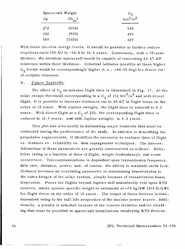
c 3 k m 2 / s 2
Spacecraft Weight
kg ( lbm 1
272 (600)
408 (900) 680 (1500)
549
49 5
429
With these vis-viva energy levels , i t should be possible to fu r the r reduce
t r i p t i m e s out to 100 AU to -14. 8 to 16 .4 yea r s .
l ifetime, the identical spacecraf t would be capable of t r ave r s ing 61-67 AU
minimum within their l i fe t imes .
C
of-ecliptic miss ions .
Conversely, with a 10-year
Celestial lat i tudes possible a t these higher
levels would be correspondingly higher (i. e ., -44-55 deg) f o r d i r e c t out- 3
E. Fu tu re Tradeoffs
The effect of C on miss ion flight t ime i s i l lustrated in F i g . 17. At the 2 2
3 so l a r escape threshold corresponding to a C of 152 k m / s and with d i r e c t
flight, i t is possible to t r a v e r s e d is tances out to 40 AU in flight t imes on the
o r d e r of 19 y e a r s .
y e a r s .
reduced to 10.5 yea r s ,
3
With Jupi te r swingby, the flight t ime i s reduced to 8 . 3
With d i r ec t flight a t a C3 of 250, the corresponding flight t ime i s
and with Jupi ter swingby, to 6 . 3 y e a r s .
This plot was a l so useful in delineating m a j o r tradeoffs that m u s t be
conducted during the per formance of the study. In addition to descr ibing the
propulsive requirements , i t identifies the necess i ty to evaluate t ime of flight
vs . distance v s . reliabil i ty v s . data management techniques.
lationships of these p a r a m e t e r s a r e g ross ly summar ized a s follows.
bility rating i s a function of t ime of flight, weight (redundancy), and event
occur rence .
data ra te , distance, power, and, of course , the abil i ty to maintain ea r th lock.
Distance becomes an overr iding pa rame te r in maintaining t ransmiss ion to
the outer fringes of the so l a r sys tem, s imply because of t r ansmiss ion beam
dispers ion .
sou rces , whose sys tem specific weight i s es t imated a t -70 kg/kW (154 lb/kW)
fo r flight t imes on the o r d e r of 10 y e a r s . The output of these devices is t ime-
dependent owing to the half- l i fe proper t ies of the nuc lear power s o u r c e . Addi-
tionally, a penalty i s attached because of the r emote isolation a n d / o r shield-
ing that must be provided in spacec ra f t installations employing RTG devices .
The i n t e r r e -
Relia-
Telecommunications is dependent upon t r ansmiss ion frequency,
Power fo r flights beyond Jupi ter will undoubtedly re ly upon RTG
J P L Technical Memorandum 33-534
F o r flight t imes on the o rde r of 10 yea r s , a m a j o r portion of the
overa l l p ro jec t cos ts may be attributable to miss ion operational costs during
fl ight.
sophisticated da ta management techniques, including on-board data p rep roc -
essing, thresholding, compression, and s torage , a s well a s modulating the
data t ransmiss ion r a t e .
One method by which to impact these costs is through the use of
F o r example, the consensus of scientists interviewed was that the
t ransmiss ion r a t e of scientific data should only be suppressed to the r ea l -
t ime data r a t e threshold. Spacecraft designers , however, a r e of the opin-
ion that the data r a t e can be fur ther suppressed by significant proportions
through the employment of on-board preprocessing techniques. Hence, the
corresponding sc ien t i f ic data ra tes a t 40 A U m a y va ry f rom, say, 1 to 4 bps
down to fract ions of bps, depending upon the on-board capabili t ies incorpo-
r a t ed . Therefore , f o r sl ight additions in spacecraf t weight, l a rge reductions
in ground station dedication and use may be rea l ized .
Although the engineering data rate m a y s t i l l be the overriding p a r a m -
e t e r , i t s frequency of occur rence and duration a r e not expected to be of suf-
f icient magnitude to inflict any exhorbitant penalt ies o r cause loss of sc ien-
tific da t a .
means of circumventing this problem a r e a . Notwithstanding, the incorpora-
tion of these and o ther data management innovations will have a significant
impact upon spacecraf t design, ground s ta t ion dedication, and overal l p r o -
g r a m c o s t s .
Storage and subsequent burst t ransmiss ion options provide fu r the r
In comparing the relative mer i t s of d i r e c t flights and Jupiter swingbys,
consideration mus t be given to weighting ce les t ia l mechanics constraints
such a s launch windows and launch years n e c e s s a r y to acqui re the Lyman-
alpha region and the sun ' s apex.
degradat ion i n the par t ic les and fields ins t ruments due to the engagement of
the hosti le Jovian environment should be weighed against the benefits of
gravi ty a s s i s t der ived f r o m the swingby. The re is, however, some degree
of inherent protect ion against the high proton densi ty due to possible built- in
shielding, uncertaint ies i n the flux density, and field dis t r ibut ion. The
pointing accuracy requirement fo r swingby acquisit ion becomes quite s eve re ,
but i t is anticipated that the type of grav i ty-ass i s t maneuver envisioned f o r
these miss ions can be successfully negotiated through ground station t racking
Additionally, the extent and period of
J P L Technical Memorandum 33- 534 27
and nominal on-board cor rec t ive maneuver capability ( -20 -50 and -170-200
m / s minimum total AV estimated, respectively, fo r guided and spin-
stabil ized escape propulsion augmentation s y s t e m s ) .
cr i t ical i ty attached to the escape co r r ido r beyond swingby encounter, a post-
engagement corrective maneuver capability i s not envisioned.
Since the re i s l i t t le
Ideally, the implementation of the powered spacecraf t conceptual
approach discussed in this r epor t re l ies on the u s e of a simple, energet ic
propulsive system that i s not s eve re ly hampered by launch windows o r ce l e s -
t i a l mechanics cons t ra in ts .
gravi ty ass i s t , a penalty i s paid i n the degradation of sophistication assigned
to the spacecraf t o r science package. Conversely, the Jupi ter swingby a l t e r -
nate may represent a m o r e nea r ly optimum tradeoff between guidance/vector
del ivery accuracy and science package / spacecraf t sophistication o r mis s ion
worth.
However, in selecting a d i r e c t flight devoid of
Of course, the launch window(s) have other fa r - reaching ramifications
that affect the relative displacement of the magnetosphere, min imum launch
energy, and hence, propellant weight. Moreover , as the vectoring accuracy
requirements become m o r e s e v e r e due to launch co r r ido r constraints , solid
propulsion sys terns become l e s s a t t rac t ive .
Although the bulk of these tradeoffs a r e outside of the scope of this
study, they a r e mentioned i n o r d e r to place the p rope r perspect ive on any
future work .
JPL Technical Memorandum 3 3 - 5 3 4
VI. CONCLUSIONS AND RECOMMENDATIONS
The following basic conclusions have been der ived f r o m this study:
1. A c l a s s of miss ions oi scientific significance ( e . g . , so l a r escape
and extra-ecl ipt ic p robes ) has been identified that could uti l ize a
s imple, energet ic propulsion s y s t e m .
2. A problem a r i s e s in that the per formance of existing launch
vehicles (as energet ic a s the Saturn V and shuttle-Centaur base-
ment vehicles) and state-of- t he -a r t mo to r s is inadequate o r
margina l .
3 . A solution has been offered in the f o r m of ta i lored solid motor
upper s tages (powered spacecraf t concept) developed to augment
launch vehicle performance. This approach would be especial ly
favorable i f t he new multistage concept based on the conesphere
moto r (Appendix A) w e r e to be adopted.
4. The advantages of such a conceptual approach include low cost,
high reliabil i ty, and reduced flight t ime.
5 . The g ross feasibil i ty of adapting solid propulsion sys t ems to the
powered spacecraf t concept has been demonstrated in conjunction
with s e v e r a l existing and projected basement vehicles .
include the space shuttle, Titan, and Titan /Centaur family launch
vehicles .
These
6 . The Jupi ter swingby al ternate was judged to b e a m o r e cost-
effective means of effecting s o l a r escape than the direct-f l ight
basel ine mis s ion .
7 . Launch energy marg ins have been identified f o r each of the m o s t
promising designs i n which the upgrading of spacecraf t sophisti-
cation and mis s ion worth can be exploited in future s tudies .
8. Advanced propulsion s y s terns and a l te rna te spacecraf t approaches
can be a s ses sed fo r m o r e advanced applications in which there is
a need f o r accura te vector del ivery requi rement .
Based on work per formed during the conduct of this study, s eve ra l
regions of high-yield payoff have been identified in which advanced technology
J P L Technical Memorandum 3 3 - 534 29
development effor ts could be fruitfully d i rec ted a t the p re sen t t i m e ,
the development of unusually high mass f rac t ion solid propellant m o t o r s .
such as
3 0 JPL Technical Memorandum 3 3 - 5 3 4
VII. RECOMMENDED FUTURE WORK
To lend fu r the r credibil i ty to the resu l t s der ived, i t i s recommended
that additional s tudies be conducted to verify the resu l t s to date and addres s
cur ren t ly unanswered quest ions. Specific recommendations f o r future work
a r e a s follows:
1. P e r f o r m a n in-depth mission application study in which in te rd is -
ciplinary inputs a r e provided to investigate the interactions of
spacecraf t propulsion (both chemical and e l ec t r i c ) , envi ronmen-
t a l constraints , data management, ground s ta t ion dedication,
spacecraf t design, mission and operational requirements , e tc . , and the i r effects on mission performance and overa l l p rog ram
cos t s .
2 . Embody maturing technologies and miss ion da ta result ing f r o m
the P ionee r flights, Outer Planets Pro jec t , and related advanced
technology development efforts to verify the conclusions drawn
to da te .
3 Exploit launch energy margins that may ex is t and upgrade the
sophistication of the scientific miss ions that can be per formed.
4. Evaluate the feasibil i ty of a l te rna te propulsive and spacecraf t
approaches to implement more sophisticated miss ion prof i les .
These approaches m a y entail the use of advanced liquid and
e lec t r ic propulsion systems o r dual-mode operat ional spacecraf t
capable of extending the mission application potential to include
s o l a r probes, rendezvous, and outer planetary p robes .
JPL Technical Memorandum 3 3 - 5 3 4 3 1
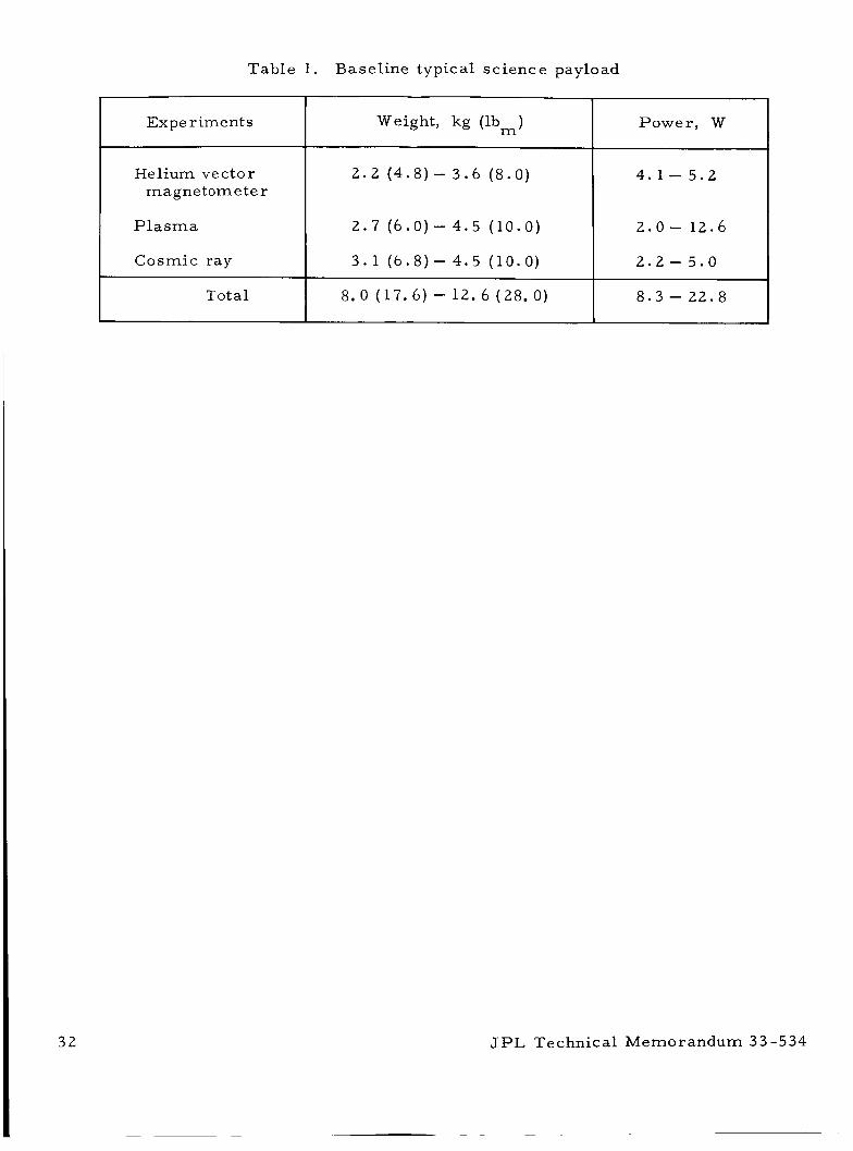
Table 1 . Baseline typical science payload
Experiments
Helium vector magnetometer
Plasma
Cosmic ray
Total
32
Weight, kg (lb ) Power, W m
2 . 2 ( 4 . 8 ) - 3.6 ( 8 . 0 ) 4.1 - 5 . 2
2 . 7 ( 6 . 0 ) - 4 . 5 (10 .0 )
3 . 1 ( 6 . 8 ) - 4 .5 (10 .0)
2 . 0 - 12.6
2 . 2 - 5 . 0
8 . 3 - 2 2 . 8 8.0 (17 .6 ) - 12. 6 (28. 0)
JPL Technical Memorandum 33-534
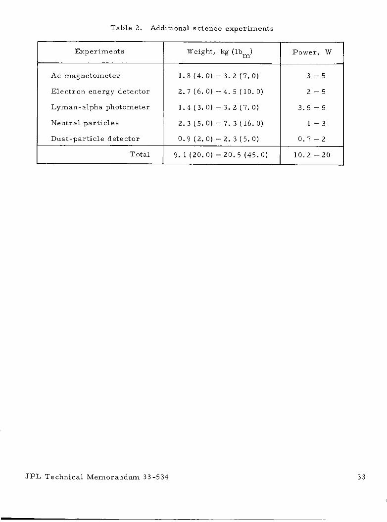
~ ~~ ~~~
Table 2. Additional science experiments
Exp er i m e nt s
Ac magnetometer
Elec t ron energy detector
Lyman - alpha photometer
Neutr a1 par t ic les
Dust -par t ic le detect o r
Total
Weight, kg (lb,)
1. 8 (4 . 0 ) - 3 . 2 (7. 0)
2. 7 (6. 0) - 4. 5 ( 10. 0)
1.4 ( 3 . 0) - 3. 2 ( 7 . 0 )
2. 3 (5 . 0 ) - 7. 3 ( 16. 0)
0 . 9 ( 2 . 0 ) - 2. 3 ( 5 . 0 )
9. 1 ( 2 0 . 0 ) - 20.5 ( 4 5 . 0 ) 1
Power, W
JPL Technical Memorandum 33-534 3 3
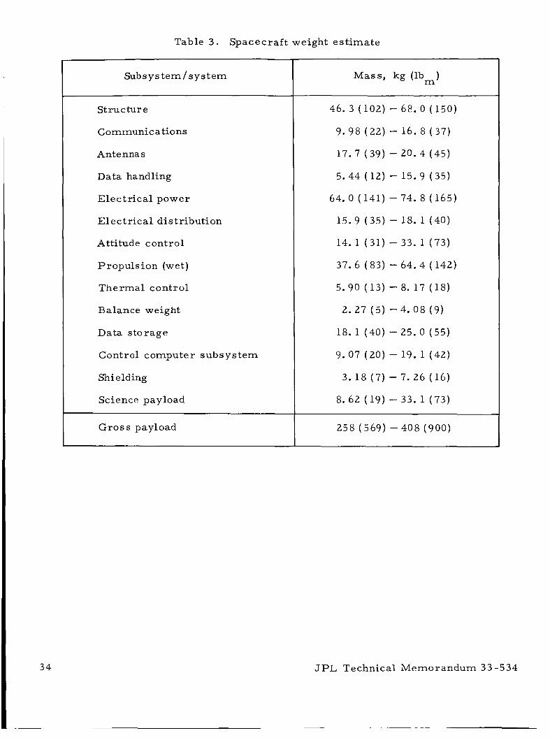
Table 3 . Spacecraf t weight es t imate
Subsys t em/sys t em
Structure
Communications
Antennas
Data handling
Elec t r ica l power
Elec t r ica l distribution
Attitude control
Propuls ion (wet)
Thermal control
Balance weight
Data s torage
Control computer subsys tem
Shielding
Science payload
Gross payload
Mass , kg (lb ) m
46. 3 (102) - 68.0 (150)
9.98 (22) - 16. 8 (37)
17.7 (39) - 20. 4 (45)
5.44 (12) - 15.9 (35)
64.0 (141) - 74. 8 (165)
15.9 (35) - 18. 1 (40)
14. 1 (31) - 33. 1 (73)
37.6 (83) - 64.4 ( 142)
5.90 (13) - 8. 17 (18)
2 . 2 7 ( 5 ) - 4 . 0 8 ( 9 )
18. 1 (40) - 25.0 (55)
- 19. 1 (42)
- 7.26 (16)
- 33.1 (73)
9.07 (20
3.18 ( 7
8.62 (19
JPL Technical Memorandum 33 -534
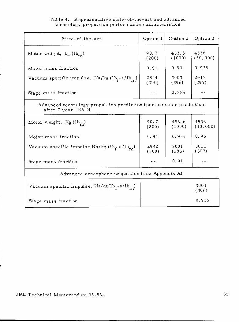
Table 4. Representat ive s ta te-of- the-ar t and advanced t e c hn ol og y p r o p ul s ion p e r f o rm a n c e char a c t e r i s t i c s
Stage mass fract ion
St at e - of -the - ar t
0.935
Motor weight, kg (lb,)
Motor mass f rac t ion
Vacuum specif ic impulse, Ns/kg ( l b f - s / l b m )
Stage mass fract ion
Option 1
0. 91
2 844 (290)
~~~
Option 2
453.6 (1000)
0 .93
2903 (296)
0. 885
Option 3
4536 (10 ,000)
0.935
2913 (297)
- -
Advanced technology propulsion prediction (pe r fo rmance predict ion after 7 y e a r s R&D)
Motor weight, Kg ( lbm)
Motor mass f rac t ion
Vacuum specific impulse Ns/kg ( lbf -s / lbm)
Stage mass fract ion
0.94
2942 (300)
453.6 (1000)
0.955
300 1 (306)
0 .91
4536 (10 ,000)
0.96
301 1 (307)
- -
Advanced conesphere propulsion ( see Appendix A)
JPL Technical Memorandum 33-534 35
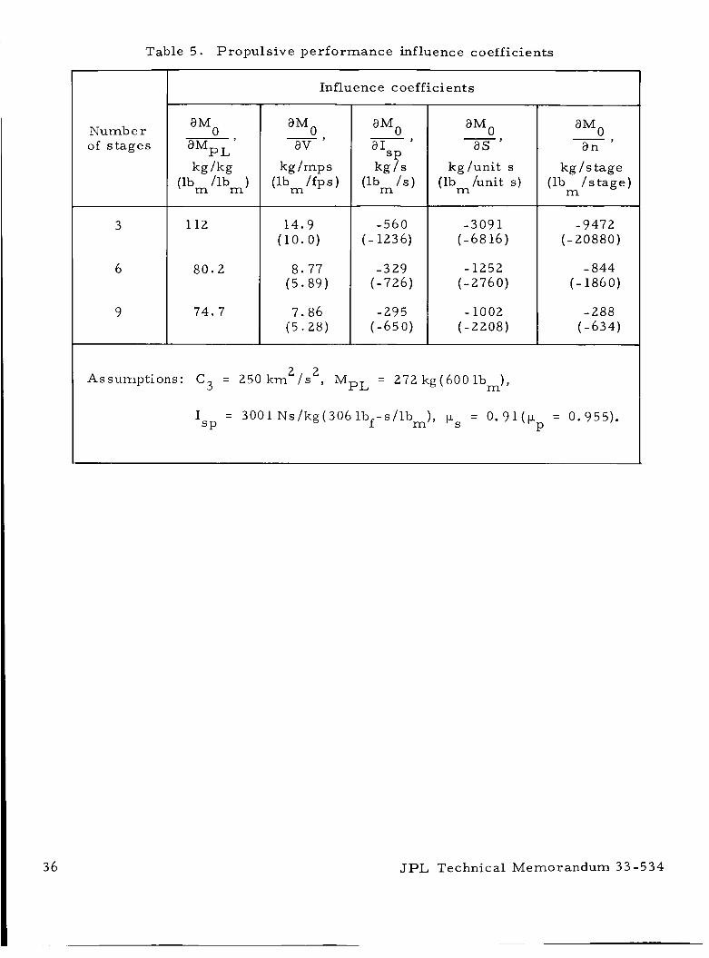
36
Table 5 . Propuls ive pe r fo rmance influence coefficients
Number of s tages
aMo aMPL kg /kg
(lb, /lb ) m
112
80 .2
74.7
Influence coefficients
a M O av - J
kg/mps (lb / fps ) m
14.9 (10.0)
8 .77 (5 .89)
7.86 (5 .28)
a M O a 1
SP kg / s
(lb / s ) m
-560 ( - 1236)
-329 (-726)
-295 (-65 0)
a M O as
kg /unit s (lb /unit s) m
-3091 (-68 16)
-1252 (-2760)
- 1002 (-2208)
a M O a n
kg / s tage (lb / s t age )
m
-9472 (-20880)
- 844 ( - 1860)
-288 (-634)
Assumptions: C3 = 250 km 2 2 / S , MpL = 272 kg(6001bm),
JPL Technical Memorandum 33 -534
~~ ~
P > 4
m U
M 3 co 0 w
W
U
M 3 N r- N
k O 0 0
x d - 2 .
E m
U
a3
r-
a
m
m II
G
aJ u I:
4
.r(
: I: u r: 2 Cl
N a 3
m O - N - 0 T r N - N N N w w N O a N N O c o o m - m o c o o m o o o m m - m m o o o 3 N - N - N - N - N N N - - N N - N N N
JPL Technical Memorandum 33 -534 37
38
Table 7. Maximum vis-viva energy levels of candidate solid upper s t ages employing aluminized propellant
and launched f r o m the space shuttle s y s t e m with a 272-kg (600-lbm) payload
6804 (1 5000)
9072 (20000)
11 340 (25000)
13608 (30000)
15876 (3 5000)
18144 (40000)
20412 (45000)
22680 (50000)
24948 ( 5 5000)
27216 (60000)
29484 (65000)
31752 (70000)
2
123
141
154
165
174
182
189
195
200
205
209
2 13
3
136
157
174
188
200
21 1
220
22 8
23 6
242
24 9
2 54
4
141
164
183
198
21 1
223
233
242
25 1
258
266
272
Number of s t ages
5
144
168
187
2 03
217
229
240
2 50
2 56
267
27 5
282
6
146
171
190
207
221
233
24 5
255
2 64
272
280
288
7
147
172
192
209
223
23 6
248
258
267
276
2 84
292
8
148
173
194
211
225
238
2 50
260
270
279
2 87
294
a M = gross upper-s tage weight (powered spacecraf t weight). 0
9
149
174
195
212
227
240
251
262
272
28 1
289
297
10
149
175
196
213
228
24 1
2 53
263
273
282
29 0
298
JPL Technical Memorandum 33 -534
c 0 a Ir: rd a, k P
3
3 M .rl
; a, M rd c, rn I k a, a sa co a,
rd 2 r3
d ;t: rd k 0 -
h
E a, c, H
4 0
rn a, I4
P d a d
h
I' n o \ 4 l n
I ' a 4 . .
d d Y Y
a r - c o I ' N I ' m
r-
n rc) co N
u? r- I' N
V
-
h
m co N
* m co N
Y
JPL Technical Memorandum 3 3 - 5 3 4 39
m
5J .d
4 rcr Q) Ql
(d 0 m a,
E 0) c, m $. m
k rd 0 !-I
m c, V a, k a k 0
rcl
I: 0 .d c, (d N
.d
.d
E .d c, a 0 $. + .d
V 0 4 : M I: M (d
.d
3;
rn a, d
2 l3
m a, M rd -e, rn bl 0 k a, P
3 A
E
a, V r: Id
k 0 cr k a, a a, V
E
4
;
t!
?
2 d 5
0 0 0 c o - a 2 . 0
a3 rr) (.,a2
A d s a + N N r-
4
n 0 0 0 O = ; Z r r )
h
0 0 rn c!
JPL Technical Memorandum 33-534
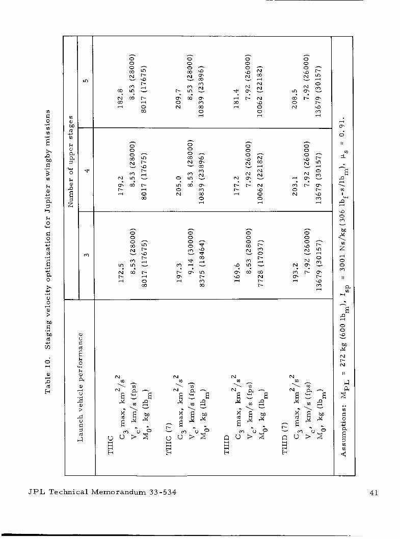
z 0 .rl v1 v1 *z CJ *s h
c
v)
k Q, c, .%-I a 3 c, k 0 %
F: 0
Id N
.rl c,
2 .rl
c, a 0
$.
V 0
c, .%-I
4 : M G M Id m
.rl
c,
0
Q,
Id
H
z I3
[I)
a, M rd 4 m k al a 9 0 k al P E z
cu u d
h
0 0 0 "
r- c o r n 5 9
h
0 0 0 -
rn c o - 2 c o
h
0 0
h
0 0
. . N c o r - co 4
4 0 co
. . r n a 5 m 0 m N co
0 d
h
0 0 O h c o 9
h
0 0
z z N m 29
h h
. . b r - N r- 9 d 0
0 d d
h
0 0 g z N r - - 9
r - r n m m r- d rr) co
h
0
. . m c o c o 9 N d r- r-
m r - r n m r- H 9
m 4
H H H b
H H H E+
-
4
e 0
II
i m
.%
E f3
2
\ m I w
9 0 rr) v
M 24 \
a rn
d
0 0 m II
a rn
H .. h
E 2
2. 0 0
2 N r- N
I I
J
2
E" <
.. v1 G 0
.%-I c,
5 rn
JPL Technical Memorandum 33-534 41
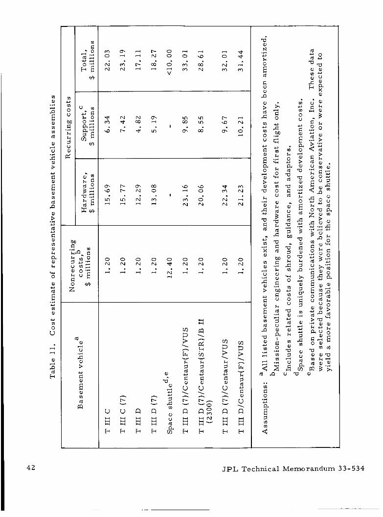
" a,
.r(
s E a, rn " Id a,
V l-4
5 3 U
i a,
" Id P
; .r( U
U Id FI a, m a, k
$- k
CH 0 a,
Id c)
E .r( U " a,
" 0
U
u 4 4
a, z b
E a, " Id B
0 0 0 0 0 0 0 0 0 N N N N T P N N N N
4 4 4 4 N 4 4 4 4 4
u
n l' Y
u
" k 0 U
2 m Id '(3 FI Id
a, U F1 Id
3 M
L
2
.cl" 3 0 k c m
rcl 0 v? U " 0 0
'(3 a,
Id a, k " a, '(3 3 0 F1
U
d
l-4
H 0
.. " F1 0
.r( U
2 2
JPL Technical Memorandum 3 3 - 5 3 4
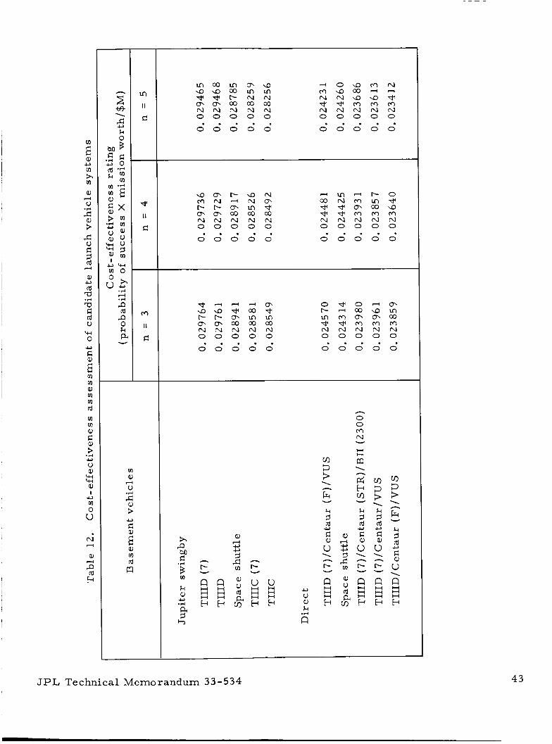
: a,
m U
2 a,
V 4
3 3
-2 FI 3 (d
a,
(d W
W FI (d u
CH 0
d
0
.+
U
E E m m al m m (d
m m al
3
u al
a, I 0 m 0
2 .+ U
z
u N
al
(d
d
51 b
Y
* II
FI
rr)
II
FI
I
m a, 4 V 3 3 0
a, m (d
a
d 0 9 r r ) N m a c o d - N N 9 9 * * * r r ) r r ) r r ) N N N N N 0 0 0 0 0
0 0 0 0 0 . . . . .
. . . . . . . . . . 0 0 0 0 0 0 0 0 0 0
n 0 0 rr) N
H l-i
1 n
Y
a
& B m k Y
JPL Technical M e m o r a n d u m 33-534 4 3
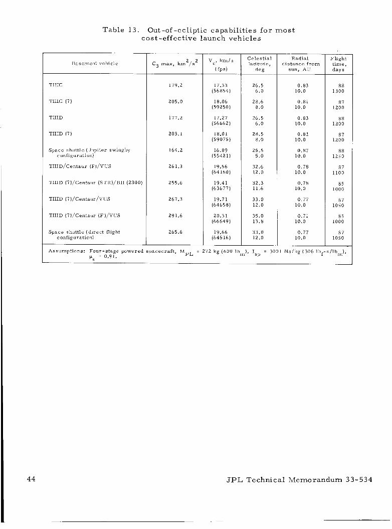
Table 13. Out -of -ecliptic capabili t ies for mos t cost-effective launch vehicles
B a s e m e n t v e h i c l e
TIIIC
TIIIC (7)
TIIID
TIIID (7)
S p a c e s h u t t l e ( J u p i t e r swingby conf igura t ion)
TI I ID/Centaur (F ) /VUS
TIIID ( 7 ) / C e n t a u r (STR)/BII (2300)
TIIID ( 7 ) / ~ e n t a u r / ~ ~ ~
TIIID (7) /Centaur ( F ) / V U S
S p a c e s h u t t l e ( d i r e c t f l ight conf igura t ion)
2 2 C 3 max, km / s
179.2
205.0
177.2
203.1
164.2
261.3
255.6
267.3
291.6
265.6
17.33 (56854)
18.06 (59250)
17.27 (56662
18.01 (59075
16.89 (55421
19.56 (64160)
19.41 (63677)
19.71 (64658)
20.31 (66649)
19.66 (64516)
C e l e s t i a l l a t i t u d e ,
d e g
26.5 6.0
28.6 8.0
26.5 6 .0
28.5 8.0
25.5 5.0
32.6 12.0
32.3 11.6
33.0 12.0
35.0 13.8
33.0 12.0
R a d i a l d i s t a n c e f r o m
sun, AU
0.83 10.0
0.81 10.0
0 .83 10.0
0.81 10.0
0.87 10.0
0.78 10.0
0.78 10.0
0.77 10.0
0.71 10.0
0.77 10.0
F l i g h t time, d a y s
8 8 1300
87 1200
88 1200
87 1200
8 8 1250
87 1100
85 1000
87 1050
85 1000
87 1050
A s s u m p t i o n s : F o u r - s t a g e p o w e r e d s p a c e c r a f t , MpL = 272 k g ( 6 0 0 lbm) , I = 3001 N s / k g ( 3 0 6 l b f - s / l b m ) , pq = 0.91. SP
JPL Technical Memorandum 33-534
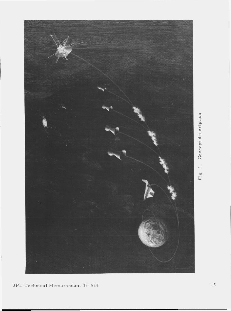
I
JPL Technica l Memorandum 33- 534 4 5
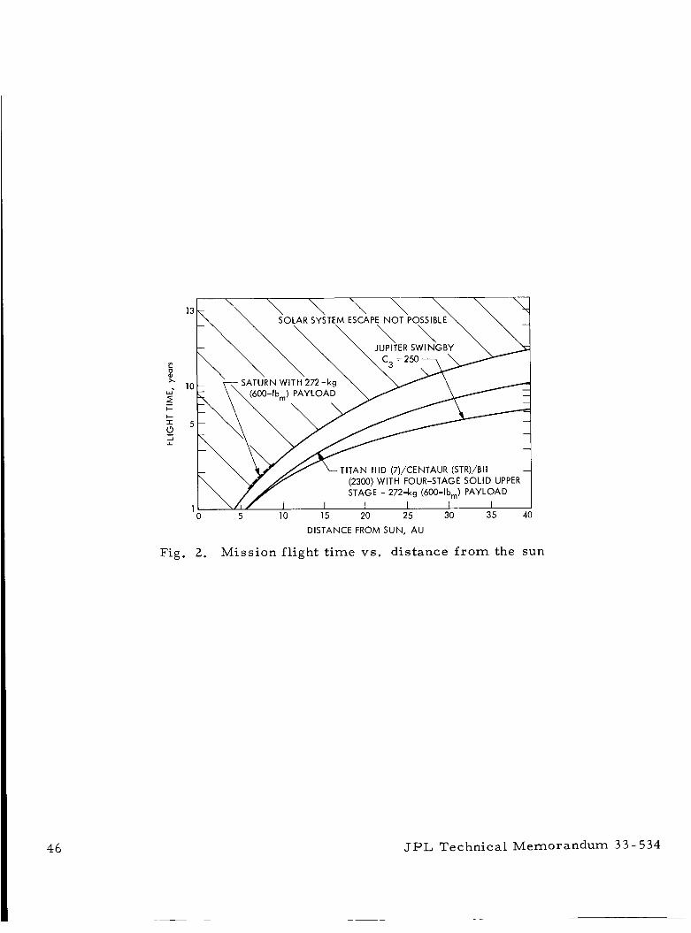
SOLAR SYSTEM ESCAPE NOT POSSIBLE \ \ \ \
5. ,,-,L ‘r SATURN WITH.272-kg \ \
TITAN Il lD (7)/CENTAUR (STR)/BII - (2300) WITH FOUR-STAGE SOLID UPPER STAGE - 272-kg (600-lbm) PAYLOAD
I I I I I 0 5 10 15 20 25 30 35 40
DISTANCE FROM SUN, AU
Fig. 2. Mission flight t ime vs. distance f r o m the sun
JPL Technical Memorandum 3 3 - 534
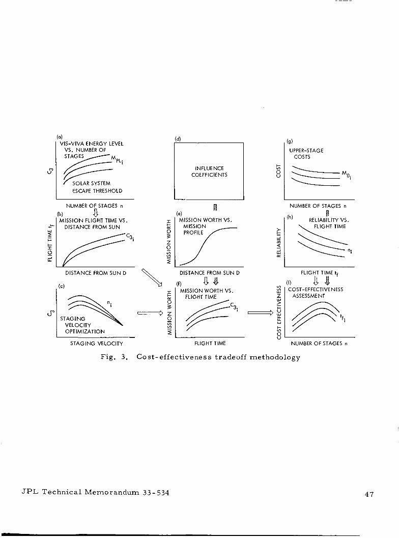
4 VIS-VIVA ENERGY LEVEL
VS. NUMBER OF STAGES
SOLAR SYSTEM ESCAPE THRESHOLD
NUMBER OF STAGES n
MISSION FLIGHT TIME VS. DISTANCE FROM SUN
r b) a
I-
!? Z
'" 0 v) E z
DISTANCE FROM SUN D
STAG I NG U"
VELOCITY I OPTIMIZATION
INFLUENCE COEFFICIENTS
ffl 4 MISSION WORTH VS.
MISSION PROFILE
DISTANCE FROM SUN D
(f) 8 8 I MISSION WORTH VS.
FLIGHT TIME
@c3i
STAGING VELOCITY FLIGHT TIME
(9) UPPER-STAGE
COSTS
NUMBER OF STAGES n
'h) RELIABILITY VS. w
FLIGHT TIME
FLIGHT TIME tf
(i) VI COST-EFFECTIVENESS
ASSESSMENT
NUMBER OF STAGES n
Fig, 3. C o s t - effective ne s s t r adeof f m e tho do logy
JPL Technical Memorandum 33- 534 4 7
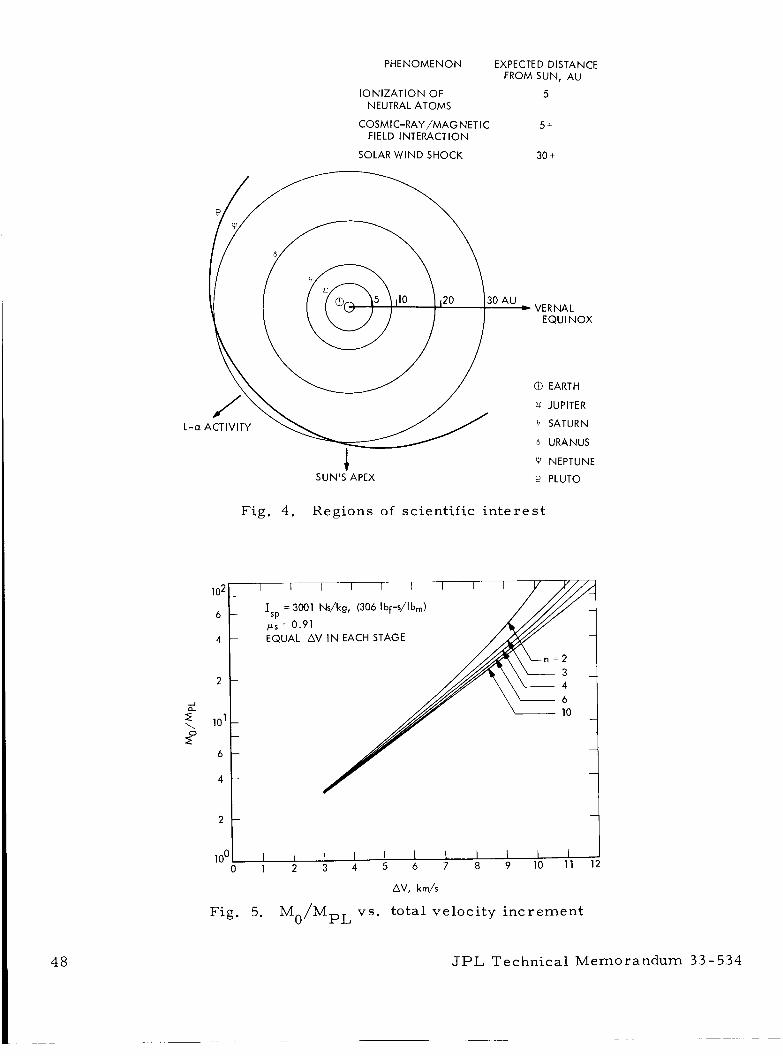
PHENOMENON EXPECTED DISTANCE FROM SUN, AU
IONIZATION OF 5
COSMIC-RAY /MAG NETlC 5 +
NEUTRAL ATOMS
FIELD INTERACTION
SOLAR WIND SHOCK 30 t
L- a
1 SUN'S APEX
Fig. 4. Regions of scientific i n t e re s t
I I I I I I I I I
. VERNAL EQUl NOX
EARTH
u JUPITER
3 SATURN
URANUS
W NEPTUNE
P PLUTO
2
I I I I I I I I I I I 0 1 2 3 4 5 6 7 8 9 10 11 12
1 oo
AV, km/s
Fig. 5. Mo/MpL vs. total velocity inc remen t
JPL Technical Memorandum 3 3 - 5 3 4
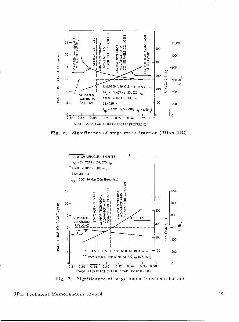
24
0) Y
d
2 > 9 2
20 O
x
++ 16 3 Q
-800
E -600 -0
d
-400
0 v 12 g
W
5 ' - 8 !=
500
400
0 Y
300 a- 0 Q
2oo 2 9
= 10,669 kg (23,520 lbm)
P 100
0 0.84 0.86 0.88 0.90 0.92 0.94 0.96 0.98
-1200
-1000
- 800
E
-600 ss a
-400
12000 r t l Oo0
t 2oo STAGE MASS FRACTION OF ESCAPE PROPULSION
Fig. 6 . Significance of stage mass fract ion (Ti tan IIIC)
LAUNCH VEHICLE = SHUTTLE I I
Mo = 24,753 kg (54,570 lbm)
' ORBIT = 185 krn (100 nm)
STAGES = 4
-&, = 3001 Ns/kg (306 Ibf-s/lb,) c Q W
u
I I I
- * TRANSIT TIME CONSTANT AT 10.4 years
** PAYLOAD CONSTANT AT 272 kg (600 Ibm)
I I 1 1 - .84 0.86 0.88 0.90 0.92 0.94 0.96 (
STAGE MASS FRACTION OF ESCAPE PROPULSION
8 0 loo 1: Fig. 7. Significance of stage m a s s f ract ion (shuttle)
JPL Technical Memorandum 33-534 49
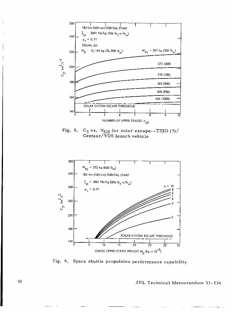
N
c N
E Y
c) U
220
260 I 185-km (100-nm) ORBITAL START
EQUAL AV
Mo = 12, 156 kg (26,800 lbm) MpL = 227 kg (500 lbm) - -
I 2 4 0 1 ps sp = 0.91
= 3001 N s h g (306 Ibf-s/lbm)
272 (600) -
318 (700)
363 (800) -
408 (900)
454 (1000) - -- -
SOLAR SYSTEM ESCAPE THRESHOLD
140 1 I I I I
140 3 4 5 6 7 8 9 10
I
NUMBER OF UPPER STAGES nus
340
300
N
N < E 260 Y
m U
220
180
Fig. 8. C 3 vs. NUS fo r so l a r escape--TIIID (7) / Centaur/VUS launch vehicle
-
-
-
-
-
380T MpL = 272 kg (600 lbm)
185-km (100-nm) ORBITAL START
I = 3001 N s h g (306 Ibf-s/lbm) SP
n = 10
Fig. 9. Space shuttle propulsion per formance capabili ty
JPL Technical Memorandum 33-534
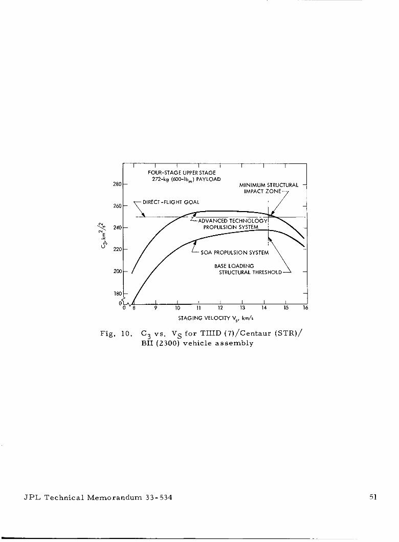
280
260
240 N
E
6i Y
" 220
2oc
180
0
I I I I I I I I FOUR-STAGE UPPER STAGE
272-kg (600-lbm) PAYLOAD M I N I M U M STRUCTURAL
IMPACT Z O N E 7
DIRECT -FLIGHT GOAL -
- / , \
SOA PROPULSION SYSTEM
-'/ BASE LOADING STRUCTURAL THRESHOLD
I I I I I 1 I 9 10 11 12 13 14 15
STAGING VELOCITY V,, km/s
Fig. 10. C3 vs . Vs fo r TIIID (7)/Centaur (STR)/ BII (2300) vehicle assembly
JPL Technical Memorandum 33- 534 51
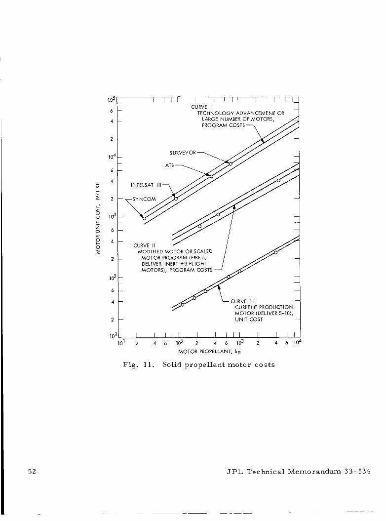
105
6
4
2
1 04
6
Y 4
E 2 I--
e
I\ - cn
8 103
P 4
I- - Z 3 6
0 z 2
Id 6
4
2
10’
CURVE I TECHNOLOGY ADVANCEMENT OR
MOTOR (DELIVER 5-10), UNIT COST
lo1 2 4 6 10’ 2 4 6 lo3 2 4 6 lo4 MOTOR PROPELLANT, kg
Fig. 11. Solid propellant motor cos ts
JPL Technical Memorandum 3 3 - 534
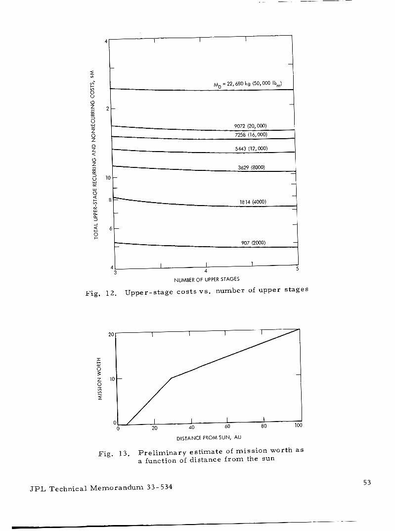
1 9072 (20,000)
7258 (1 6,000)
5443 (12,000)
3629 (8000) - -
- 18 14 (4000)
907 (2000)
4
NUMBER OF UPPER STAGES
5
Fig. 12. Upper-stage costs vs. number of upper s tages
DISTANCE FROM SUN, AU
Fig. 13. Pre l iminary est imate of miss ion worth as a function of distance f r o m the sun
JPL Technical Memorandum 33- 534 53
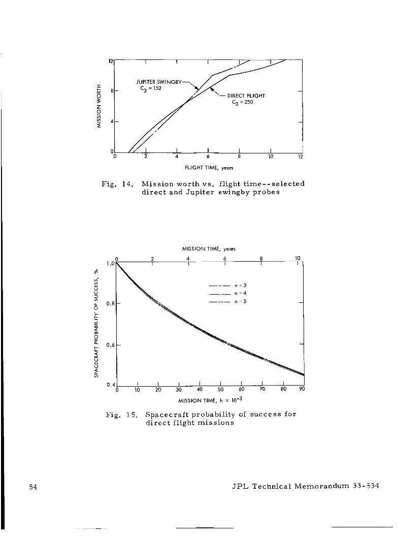
I/
JUPITER SWINGBY C3 = 152
C3 = 250
2 4 6 8 10
FLIGHT TIME, yeals
Fig . 14. Mission worth vs. flight t ime--se lec ted d i r ec t and Jupi ter swingby probes
MISSION TIME, years
I I I I I I I I I 0 10 20 30 40 50 60 70 80 90
MISSION TIME, h X
Fig. 15. Spacecraf t probability of success fo r d i r e c t flight mi s s ions
JPL Technical Memorandum 33-534
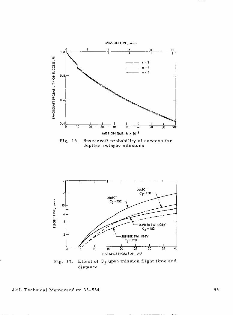
MISSION TIME, yean
I I I I I 1 I 1 0 10 20 30 40 50 60 70 80
MISSIONTIME, h x 10-3
Fig. 16. Spacecraf t probability of success for Jupiter swingby mis s ions
Fig. 17. Effect of C3 upon mis s ion flight t ime and distance
JPL Technical Memorandum 33-534 55
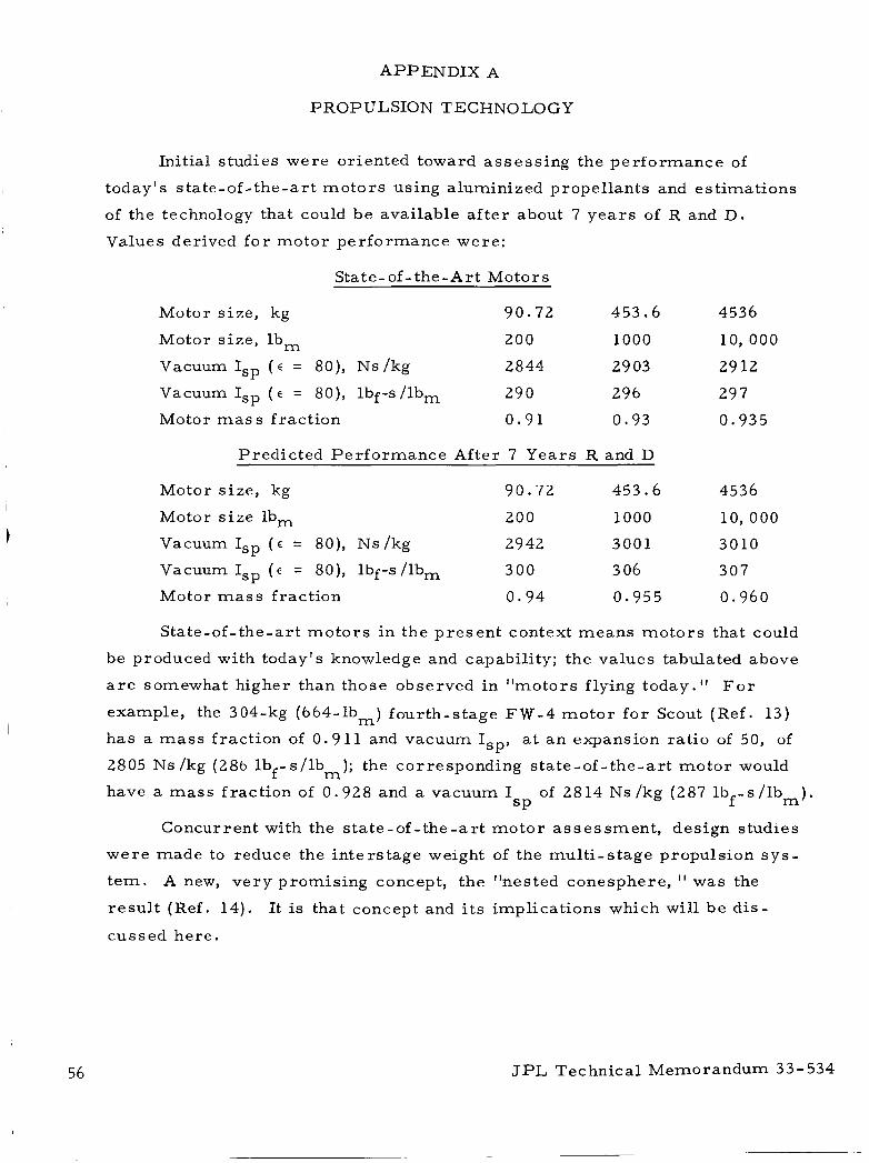
APPENDIX A
PROPULSION TECHNOLOGY
Initial studies w e r e oriented toward a s ses s ing the per formance of
today's s ta te-of- the-ar t m o t o r s using aluminized propel lants and est imat ions
of the technology that could b e available a f t e r about 7 y e a r s of R and D .
Values derived f o r motor per formance were :
Stat e- of - the - A r t Motors
Motor s ize , kg 90.72 453.6 4536
Motor s ize , lb, 200 1000 10,000
Vacuum Isp ( E = 80), Ns/kg 2844 29 03 29 12
Vacuum Isp ( E = 80), lbf-s /lbm 29 0 296 29 '7
Motor mass fract ion 0 .91 0 .93 0.935
Predic ted Pe r fo rmance After 7 Years R and D
Motor s ize , kg 90.72 453.6 4536
Motor s i ze lb, 200 1000 10,000
Vacuum Isp ( E = 80), Ns/kg 2942 3001 3010
Vacuum Isp ( E = 80), lbf-s/lbm 300 3 06 307
Motor mass fract ion 0 .94 0.955 0.960
State-of-the-art m o t o r s i n the p re sen t context m e a n s m o t o r s that could
be produced with today's knowledge and capability; the values tabulated above
a r e somewhat higher than those observed in "motors flying today." F o r
example, the 304-kg (664-1bm) fourth-s tage FW-4 m o t o r f o r Scout (Ref . 13)
has a mass fract ion of 0 .911 and vacuum I a t a n expansion ra t io of 50, of SPY 2805 Ns /kg (286 lbf-s / lbm); the corresponding s ta te-of- the-ar t mo to r would
have a m a s s f rac t ion of 0 .928 and a vacuum I of 2814 Ns /kg (287 lbf -s / lbm) . SP
Concurrent with the s ta te -of - the-ar t mo to r a s ses smen t , design studies
w e r e made to reduce the in te rs tage weight of the mul t i - s tage propulsion s y s -
t e m . A new, v e r y promis ing concept, the "nested conesphere, " was the
r e su l t (Ref. 14).
cussed here .
It is that concept and i t s implications which will b e d i s -
56 JPL Technical Memorandum 33-534
I . NESTED CONESPHERE CONCEPT
In a conventional design of a spacecraf t with a four -s tage solid
propulsion system, shown schematically a t the top of F i g . A-1, the moto r s
would have shor t length-to-diameter ratios, r a the r l a rge nozzles f o r space
operation, and would be coupled with inters tage s t ruc tu re .
reduce the iner t weight of the propulsion sys t em significantly, i t was pro-
posed that the inters tage s t r u c t u r e b e eliminated by using the nozzles a s
s t ruc ture , a s shown i n the second configuration.
In o r d e r to
An examination of the second assembly shows that the volume efficiency
is much lower than des i red ; the chambers would contain propellant but the
relat ively la rge nozzles would not. Therefore, in the third configuration,
the chambers were reshaped and nested in the nozzle ahead in o r d e r to
shor ten the overal l assembly length about 2 0 % .
However, the nozzle and chamber then constitute redundant s t r u c t u r e s .
Thus, in the final configuration, the three redundant nozzles would be e l im-
inated.
f i r ing of a given stage, and a s a nozzle during the f i r ing of the next s tage .
The in tegra l chamber-nozzle component i s then called a chamzle ( see
F i g . A-2 ) .
The chamber would be used a s a propellant container during the
In o r d e r f o r the motors to function a s descr ibed, i t is necessa ry to have
a c losure o r isolation plug in the forward end of each chamzle - - to prevent
preignition of the next motor - - and a separation mechanism ( see i n s e r t
F i g . A - 2 ) to s tage off the spher ica l portion and its nozzle a f t e r the propellant
burns out of the chamzle.
nism, such a s a flexible, l inear-shaped charge, automatically produces the
nozzle f o r the next motor f i r ing .
Staging off the af t portion by a separat ion mecha -
In summary , the motors could operate a s follows:
1 . The igniter f i r e s the la rges t motor , and i t s propellant burns out
completely. After about 5 to 10 s , a circui t i n the payload sec -
tion f i r e s the flexible, l inear-shaped charge of the motor , s tag-
ing off the spher ica l section of the chamzle and i t s nozzle, thus
creating the new nozzle f o r the next s tage.
JPL Technical Memorandum 33-534 57
2 . On signal f r o m the fir ing circui t , the next- largest motor is
ignited, expelling i t s nozzle isolation plug. The propellant
burns out entirely, and staging i s again effected, creating a new
nozzle. The sequence of events i s repeated fo r motors 3 and 4.
However, all of motor 4 would probably be staged off in o r d e r to
reduce the thermal-control requi rement on the spacecraf t . * It should be noted that i f the chamzle is to s e r v e a s a nozzle l a t e r , i t
probably should be made of a n a l l -carbon composite (a carbon m a t r i x with
reinforcing carbon f ibe r s ) . Such a design d r a w s on and extends the recent
a l l -carbon technology developed f o r nozzles in JPL's long-burning motor
p rogram (Ref. 15) . The nozzle and af t end of the chamzle, of course, wil l
operate while radiating heat to space, with sur face equilibrium t empera tu res
a s high as 1093 to 1649°C (2000 to 3000°F).
There a r e assembly joints, shown a s threaded m e m b e r s in F i g . A-2,
Thus, there would in each motor fo r manufacturing and shipping purposes .
be four chamzles with loaded propellant and one separa te nozzle for the
l a rges t motor during shipment for propulsion sys t em assembly a t the Cape.
The igni ters i n each motor will probably be located n e a r the motor
assembly joint.
has not been fixed, though they may well come f r o m the payload internally
along the axis of the moto r s to the respect ive ign i te rs .
using f iber optics a r e under review (Ref. 16). Alternately, automatic igni-
tion f r o m stage to s tage, with a pyrotechnic t ime delay between motors , is
a l so under consideration.
The exact method and routing of fir ing l ines to the ign i te rs
L a s e r techniques
At this s tage in the study, the motors have been kept a s s imple i n ope r -
ation a s possible.
depletion.
vector control.
There would be no thrus t termination; all mo to r s burn to
In addition, i t has been assumed that there would be no thrus t
Thrus t misal ignment would be compensated f o r by spinning
*Subsequent studies m a y show that the chamzle shape of s tage 4 should be m o r e conventional in o rde r to rea l ize additional per formance , even though the scaling pr inciple f o r that s tage would be abandoned and development cos ts would i n c r e a s e .
JPL Technical Memorandum 3 3 - 5 3 4
during motor burn .
a r e des i rab le and t h r u s t vectoring methods a r e needed, the design study
should be extended to include that feature .
If later analysis* reveals that Jupi ter swingby miss ions
Burning times range f r o m 8 0 s f o r the sma l l e s t mo to r to about 201 s
fo r the l a r g e s t .
would b e about 6 . 1 g . However, f o r acceleration-sensit ive payloads, the
maximum accelerat ion could be reduced to about half to two-thirds that value
with only a small penalty i n propulsion per formance .
Maximum acceleration with a 272-kg (600-lb,) payload
F o r a 10, 660-kg (23, 500-lbm) assembly (spacecraf t and escape p r o -
pulsion), the overal l length would be approximately 9 m (29.7 f t ) and the
maximum chamzle d i ame te r about 1 . 8 m (6 f t ) .
It should be pointed out that each moto r is a t rue scale model of the
other t h ree . Diameters , lengths, and thicknesses a r e scaled by the s a m e
l inear f ac to r .
propulsion development costs . II.
As will be noted l a t e r , this is important for reducing the
CRITICAL DESIGN AREAS AND POTENTIAL PERFORMANCE
There a r e s o m e potential problem a r e a s in the concept; however, i t is
planned to initiate advanced development work on cr i t i ca l questions under
NASA sponsorship ve ry soon.
First, a vacuum specific impulse of 3001 Ns/kg (306 lbf-s/lb,) has been
assumed f o r the new class of aluminized** hydroxy- terminated polybutadiene
propellant cur ren t ly under development. The bes t predicted value fo r today's
propellant is 2903 Ns/kg (296 lbf-s/lbm), 98 Ns/kg lower than the assumedvalue
However, a new concept under examination (Ref. 17) fo r ra is ing the effi-
ciency of me ta l combustion p rocesses in solid propellants (ammonium p e r -
chlorate with occluded aluminum) may provide the potential improvement
indicated. If, a l ternately, no increase i n I w e r e real ized, a n equivalent SP
$<Some pre l iminary calculations indicate that a Jupi ter swingby could be c a r r i e d out by despinning the spacecraft a f te r staging off the four solid propel lant m o t o r s and providing midcourse correction, impulse control, and three-axis attitude stabilization with e lec t r ic t h rus t e r s and m i c r o - p u l s e r s .
because of the complicating fac tor of toxicity.
Thrus t vectoring the solid motors probably can b e avoided.
**Berylliumized solid propellants were omitted f r o m the study at this t ime
JPL Technical Memorandum 33-534 59
60
reduction i n mass fract ion of 0 .007 f r o m the mass f rac t ions noted l a t e r
would resul t .
a rd i ze the proposed propulsion concept.
Although that is a significant penalty, i t is not enough to jeop-
The second problem a r e a , preignition of propellant f r o m high hea t
t r ans fe r i n the chamzle, a r i s e s because the l a t t e r is made of carbon, and
carbon is a good thermal conductor .
ducted f rom the nozzle along the spher ica l wal l .
has been provided to isolate the propellant and prevent preignition, a good
the rma l analysis mus t be made to be s u r e that preignition of the propellant
and the explosive separat ion device won ' t o c c u r .
Shortly a f te r ignition, heat will b e con-
Although chamzle insulation
The third problem a r e a , pyrotechnic separa t ion of the carbon chamzle ,
o r staging, is c r i t i ca l to the concept. The carbon chamzle is brit t le, even
though the carbon reinforcement f ibe r s toughen the s t r u c t u r e marked ly . When
staging i s attempted, f i r ing the flexible, l inear-shaped charge might c rack ,
o r even shat ter ,
uled to check the validity of the separat ion concept.
the next-s tage nozzle . Ea r ly experimental t e s t s a r e sched-
A backup design is cur ren t ly under examination, but it is too e a r l y t o
a s s e s s its mer i t s and d e m e r i t s .
the shock of the chamzle and f r ac tu re mechanics to control the cleavage and
f r ac tu re environment. The penalty i n mass fract ion, i f the backup must be
used , is not expected to be l a r g e .
It would u s e detonation pr inciples to shape
The fourth problem a r e a involves the advancement required i n the
technology of the a l l -carbon composites used as nozzles and chamzles .
p re sen t a l l -carbon technology employs a fabricat ion technique based on a
rose t te layup.
ically f i red successfully in th ree out of t h r e e t e s t s without s t ruc tu ra l f a i lu re s
and with negligible e ros ion .
factor i ly fired two out of two al l -carbon nozz les . If th is technology w e r e
extended f r o m the nozzle to include the chamber , and those concerned believe
i t can be, the conesphere moto r mass f rac t ion es t imate would be 0.917 and
the overa l l stage mass fract ion 0 .907 .
The
Recently, two JPL nozzles fabr icated in this way w e r e s ta t -
Thiokol Chemical Corporat ion h a s a l so s a t i s -
However, the technology offers a potential capability wel l beyond that
The new method of fabr icat ion would uti l ize filament-winding of (Ref . 18).
high strength, high-modulus carbon f i laments ( such as Thornel 50) , and
JPL Technical Memorandum 3 3 - 5 3 4
format ion of the carbon ma t r ix in the in te rs t ices between f ibers by chemical
vapor deposition (CVD).
mens have shown tensi le and inter laminar s h e a r values 2 to 2-1/2 t imes
those of the rose t te layup mater ia l (Refs . 19 and 2 0 ) .
p roper t ies can be real ized in the chamzle, the average moto r m a s s f ract ion
should i n c r e a s e to about 0 .945 and the s tage m a s s f rac t ion to about 0.935.
F o r comparison, today's s ta te -of - the-ar t mo to r s have a motor m a s s f rac t ion
of 0 .93 and a s tage m a s s fraction, including in te rs tage s t ruc tu ra l weights, of
0 .885 . F igu res 6 and 7 in the text show the significant i nc rease in propulsion
payload that resu l t s f r o m such a n increase in s tage m a s s f ract ion and use of
the conesphere concept.
Filament-wound cylindrical and other t e s t speci-
If those mechanical
I t is self-evident that a m a j o r development effort i n the carbon-
composite technology a r e a will be necessa ry i f the advanced concept is to be
rea l ized . Fortunately, other investigators, the Naval Ordnance Laboratory
and the Sandia Corporation, a r e a l so developing carbon composites, and the i r
work would supplement the planned technology ef for t s .
III. PROPULSION DEVELOPMENT COSTS AND RECURRING COSTS
Any concept that requi res four completely new moto r s based on ve ry
advanced technology would r e su l t i n la rge development cos ts i f the conven-
tional method of developing and procuring moto r s were adopted.
Gin (Ref . 21) has determined the relationship of p r o g r a m development costs
to motor s ize for such solid propellant mo to r s a s SYNCOM, Intelsat 111, the
Applications Technology Satellite apogee motor , and Surveyor, i . e . , p r o -
g r a m s in which the s ta te -of - the-ar t was being advanced, a s i t is in the
moto r s under consideration ( s e e F i g . 11, curve I) . With that relationship a s
a bas i s , the development costs for four s tages of escape propulsion totaling
10, 660 kg (23, 500 lb,) have been estimated a t $61 .1 X 10 , assuming a con-
ventional development approach.
Winston
6
See Table A- 1 fo r the breakdown by s t ages .
F o r the concept under discussion, a n a l te rna te approach is advocated.
I t would capitalize on the scaling laws in o rde r to reduce propulsion develop-
men t cos ts significantly and i s based upon the following rat ionale . It has
been demonstrated i n the Sergeant program, and verified in the SYNCOM and
Applications Technology Satellite motor p rograms , that subscale motors of a
much l a r g e r motor could be used to predict the p r e s s u r e and thrus t t ime
h is togram of the l a r g e r motor (Ref. 1) i f a l l mo to r dimensions a r e scaled
J P L Technical Memorandum 3 3 - 534 6 1
6 2
l inear ly and the charge design and propellant a r e maintained.
analysis of the motor and the propellant charge a l so reveals that, provided
body forces a r e relatively insignificant, s t r e s s e s in the moto r and propel lant
a r e independent of s ca l e . The heat t r ans fe r i n the nozzle sca l e s a s DOe2 and
resu l t s , therefore, in slightly conservat ive conditions on scaling up.. The
specif ic impulse of the aluminized propellant tends to inc rease sl ightly with
increas ing s ize because two-phase flow los ses a r e lower a t the l a r g e r s i z e .
A s t r e s s
Combustion instabil i ty and charge c reep (o r s lump) do not sca le ; how-
eve r , the la t te r appears to be no problem with the propellants and motor
s i zes proposed.
quently af ter aluminum was introduced into solid propellant formulat ions, but
as propellants have become m o r e energet ic , i t has reappeared on some occa-
s ions (as may be the case with the powered spacecraf t application). Fo r tu -
nately, a s Brownlee (Ref. 2 2 ) showed, the tendency f o r a motor to resonate
acoustically dec reases with decreas ing chamber p r e s s u r e and with d e c r e a s -
ing L / D .
The tendency i s reduced even fur ther if one changes f r o m Brownlee 's internal
rad ia l burning design to a n end-burning des ign .
te red , there a r e seve ra l methods fo r i ts elimination, such as resonance rods
o r baff les , though none is ideal o r without some per formance penalty.
In the past , combustion instabil i ty was observed only in f r e -
(The tailored solid upper s tages will have low values in both cases . )
If instabil i ty were encoun-
In summary, this sca led-motor approach consis ts of developing one of
the sma l l e r motors in o r d e r to advance the technology and the high level
des i r ed a t the lowest cost , while using numerous sma l l motors to evaluate
a l l problematical aspects in o r d e r to es tabl ish a high confidence in the r e l i -
abil i ty of the bas ic design.
a r e scaled-up motors , ball ist ically and s t resswise , ve ry l i t t le additional
development would be needed.
d i rec t ly , then three moto r s each would be de l ivered .
ings f o r any one motor would consti tute successfu l s ta t ic f i r ings f o r a l l mo to r
s i zes because each is a sca le model of the o t h e r s . This technique pe rmi t s
u s e of a single optimum-sized motor in each s tage, so that near-opt imum
spacecraf t performance would be available a t high reliabil i ty and high confi-
dence levels .
Because the l a r g e r m o t o r s fo r all other s tages
The l a r g e r moto r s would be fabricated
Successful s ta t ic f ir-
The cost of developing the f i r s t , s m a l l e s t mo to r through flight, because
of the comprehensive program, is es t imated a t $ 9 . 5 million, a lmost double
JPL Technical Memorandum 3 3 - 5 3 4
the 5 . 2 mill ion est imated for the same motor using conventional development
methods ( see Table A - 1) .
l a r g e r , l inear ly scaled moto r s would be manufactured, and their pe r fo rm-
ance would be ver i f ied in a f ive-motor qualification p r o g r a m ( see curve 11 of
F i g . 11) . Motor manufac turers a r e current ly performing f ive-motor qualifi-
cation testing of modified moto r s .
lengthened, modified with a different propellant, o r a l te red slightly in design.
Using indus t ry ' s costs for modified motor p rograms f o r the three l a r g e s t
mo to r s , the total proposed scaled-motor p rogram would be $19. 1 mill ion, o r
about 30% of the m o r e conventional development p rogram cos t s .
g r a m totals include propulsion costs for development to flight, qualification
f i r ings, and de l ivery of one i n e r t motor and th ree flight motors fo r each of
the four s t ages .
With the sma l l e s t mo to r qualified, the three
These a r e off-the-shelf motors that a r e
Both p r o -
Drawing on indus t ry ' s experience, f r o m f ixed-price production con-
t r ac t s , the production or r ecu r r ing cost of one se t of four motors , when
ordered i n lots of five o r ten, would be about $ 0 . 8 mil l ion to 1 mill ion p e r
s e t of fou r .
t em design has been looked a t in grea te r de ta i l .
IV. CONCLUSIONS
Obviously, these cos t es t imates m u s t be verified when the s y s -
As a resu l t of the propulsion analyses to date, i t can be concluded that
1. A stage m a s s f ract ion of 0.935 is technically feasible through
u s e of the conesphere concept and the advanced al l -carbon com-
posi te technology; growth potential beyond this appears to ex is t .
The cos t of developing four scaled motors can be reduced to
about 3 0% of conventional development cos ts through application
of the scaling laws .
2 .
JPL Technical Memorandum 33-534 63
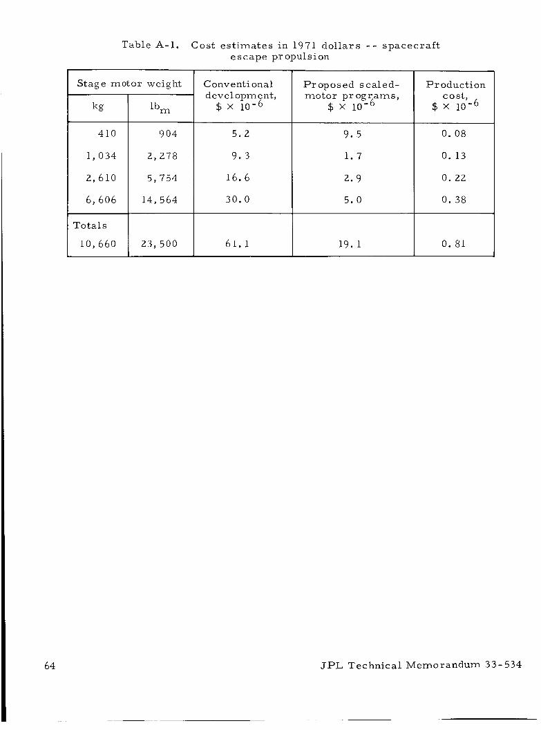
Table A-1. C o s t es t imates in 1971 dollars - - spacecraf t escape propulsion
JPL Technical Memorandum 33-534
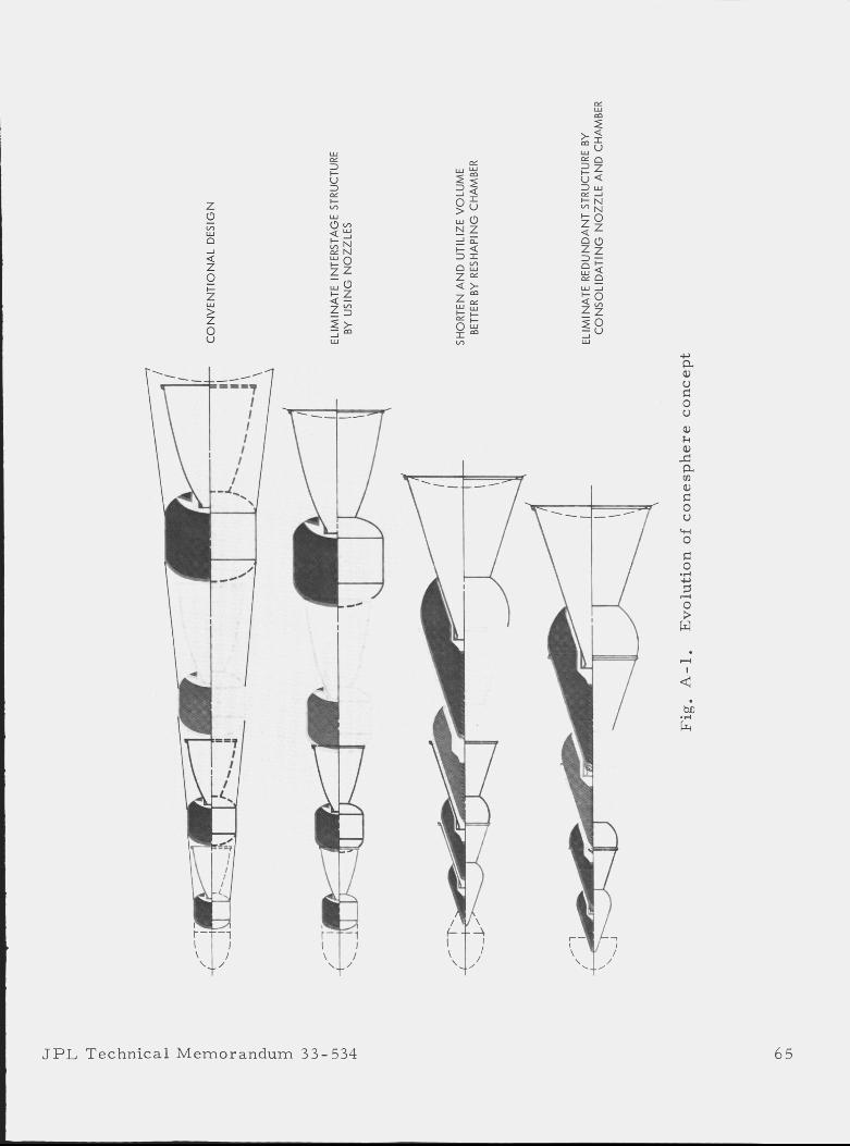
Z c3
d 0 t
8
v) W
0
Z
w > Z
1 JPL Technica l Memorandum 33-534 65
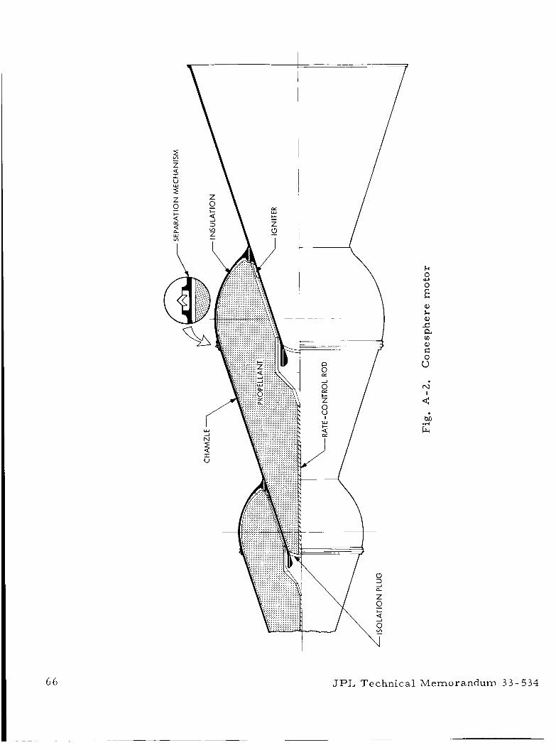
k 0 c, : a, k Q) c a m
2 0 u
66 JPL Techn ica l Memorandum 3 3 - 534
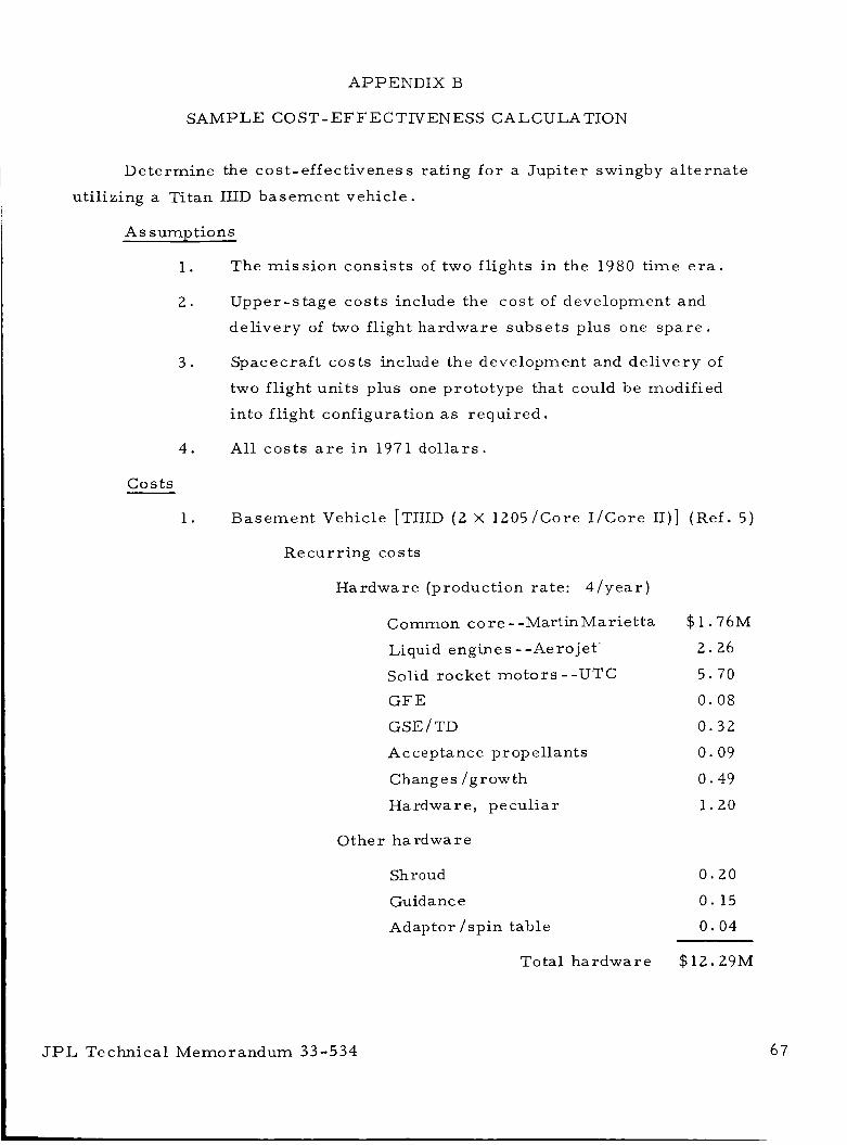
APPENDIX B
SAMPLE COST-EFFECTIVENESS CALCULATION
Determine the cost-effectiveness rating fo r a Jupi te r swingby a l te rna te
utilizing a Titan ILID basement vehicle.
Assumptions
1. The mis s ion consis ts of two flights in the 1980 t ime e r a .
2 . Upper-s tage cos ts include the cost of development and
de l ivery of two flight hardware subse ts plus one s p a r e .
3 . Spacecraf t costs include the development and de l ivery of
two flight units plus one prototype that could be modified
into flight configuration as requi red .
4. All cos ts a r e i n 1971 do l l a r s .
c o s t s
1. Basement Vehicle [TIIID (2 X 1205/Core I /Core 11)] (Ref . 5 )
Recurr ing costs
Hardware (production rate: 4 / y e a r )
Common c o r e - -Martin Mar ie t ta
Liquid engines - -Aerojet '
Solid rocket mo to r s - -UTC GF E
GSE / TD
Acceptance prop ellants
Changes /growth
Hardwar e, pecul iar
0 the r ha rdwa r e
Shroud
Guidance
Adaptor /spin table
To tal hardware
$1.76M
2 .26
5 .70
0 . 0 8
0 . 3 2
0.09
0.49
1.20
0 .20
0 . 15
0 . 0 4
$12.29M
JPL Technical Memorandum 33-534 67
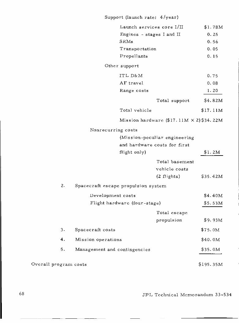
Support (launch ra te : 4 / y e a r )
Launch se rv ices c o r e 1/11 $1.78M
Engines - s tages I and I1 0. 25
S RMs 0. 56
T r an s po r ta t i on 0. 05
Propel lants 0. 15
Other support
I T L D&M 0.75
A F t r ave l 0. 08
Range cos t s 1 . 2 0
Total support $4.82M
Total vehicle $17. 11M
Mission ha rdware ($17. 11M X 2)$34. 22M
Nonrecurr ing cos ts
(Miss ion-peculiar engineering
and ha rdware cos t s for first
flight only) $ 1 . 2M
Total basement
vehicle cos t s
(2 fl ights) $35.42M
2. Spacecraf t escape propulsion s y s t e m
Development cos t s $4.40M
Flight hardware (four -s tage) $5.53M
Total escape
propulsion $9. 93M
3. Spacecraf t cos ts $75. OM
4. Mission operat ions $40. OM
5. Management and contingencies $35. OM
Overa l l p rog ram cos ts $195. 35M
68 JPL Technical Memorandum 3 3 - 5 3 4
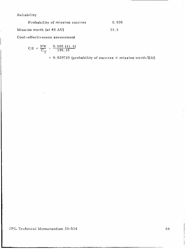
Reliability
Probabi l i ty of mission success
Mission worth (at 40 AU)
0.505
11 .5
Cost-effectiveness a s ses smen t
P W - 0 .505 (11.5) C E = - - 195.35 cT
= 0. 029729 (probability of success X miss ion worth/$M)
JPL Technical Memorandum 3 3 - 5 3 4 69
REFERENCES
1.
2.
3.
4 .
5.
6.
7.
8.
9.
10.
11.
12.
13.
Landsbaum, E. M . , and Schumacher , J. C . , "Comparison of Ballistic Proper t ies of Scale-Model and Ful l Size Sergeant Motors , I '
Publication NO. 141, Je t Propuls ion Laboratory, Pasadena , Calif. , 1958. (CONFIDENTIAL)
Shafer, J. I. , "Propulsion Cost Es t imates , ' I Internal Document, IOM 381 -71 -75, Jet Propuls ion Laboratory, Pasadena, Calif. , October 6, 1971.
Launch Vehicle Estimating Factors, NASA Document NHB 7100. 5, January 1 97 1.
Phen, R. L . , "Pre l iminary Study of the Impact of the Space Shuttle on P lane tary Propulsion, I ' Internal Document, Jet Propuls ion Laboratory, Pasadena, Cal i f . , Feb rua ry 25, 1971
Economic D a t a Document, 1971, OSSA Document BMI-NLVP-DD-3 -(71), 1971.
"TOPS Spacecraf t Probabili ty of Success for One Spacecraf t , ' I TOPS Pro jec t Review 111, Internal Document, Jet Propuls ion Laboratory, Pasadena, Cal i f . , April 9-10, 1970.
Robillard, C. L . , Summary of the Meeting of the Panel on Reliability of Large Solid-Propellant Motors, Technical Memorandum 33 -219, Jet Propuls ion Laboratory, Pasadena, Cal i f . , May 10, 1965.
Martin, P. J. , Reliability Estimation for Chemical Propuls ion System, SRI P ro jec t MSU-8075, Stanford Resea rch Insti tute, Stanford, Calif. , May 1970.
Don, J. P . , and Phen, R. L . , Application of Hybrid Propuls ion Systems to P lane tary Missions, Technical Memorandum 33 -483, Jet Propuls ion Laboratory, Pasadena, Calif. , November 1, 197 1.
Feasibil i ty Study for a Multi-Mission Electr ic Propuls ion Spacecraf t (Pioneer Concept), TRW Report No. 18305-6001 -R000, Redondo Beach, Cal i f . , June 18, 1971.
Solar Electr ic Multi Mission Spacecraf t (SEMMS) Phase A Final Report , Technical Summary, Internal Report No. 617-2, Je t Propuls ion Laboratory, Pasadena, Calif. , September 197 1.
Study of a Common Solar -Elec t r ic -Propuls ion Upper Stage for High- Enerizv Unmanned Missions. Vol. I. TRW ReDort No. 16552-6006-R0-00, Redoido Beach, Cal i f . , July 1971. '
Rocket Motor Manual, SPIA/MI Vol. 11, Unit 480, Chemical Propel lant Information Agency, Johns Hopkins University, Applied Physics Laboratory, Silver Spring, Maryland, October 1968. (CONFIDENTIAL)
J P L Technical Memorandum 33- 534

14.
15.
16.
17.
18.
19.
20.
21.
22.
Bamford, R. and Shafer , J. I . , "Staged Solid Propel lant Motors , I '
NASA Invention Report 30-13080, October 8 , 1971.
Bailey, R. L. and Carmichael, D. E. , Pyrolyzed Mater ia ls Nozzle, 1971 JANNAF Combined Propulsion Meeting, C P I A Publication 219, Vol. I, pp. 153-167, Chemical Propellant Information Agency, Johns Hopkins University, Applied Physics Laboratory, Si lver Spring, Maryland, October 197 1.
Menichelli, V. J. , and Yang, L. C . , Sensitivity of Explosives to L a s e r Energy, Technical Report 32-1474, Je t Propuls ion Laboratory, Pasadena , Calif. , April 30, 1970.
Simmons, G. M. , and Shafer, J. I . , "Solid Propel lants Using Occluded Metal Fuel , I t NASA Invention Report 30 - 11 975, December 6, 1971.
Coulbert , C. D. , Pyrolytic Refractory Mater ia ls for Spacecraf t Thrus t Chambers , Composite Thrus t Chambers for the Per iod July 23, 1968 to Feb. 22, 1970, Report No. S989, The Marquardt Co. , Van Nuys, Cal i f . , May 7, 1971.
Kotlensky, W. V. , and Bauer, D. W . , Mechanical P rope r t i e s of I so thermal CVD Carbon Infiltrated Carbon and Graphite Fi lament Wound Cylinders, Supertemp Co. , Santa F e Springs, Calif. P a p e r presented at 10th Biannual Conference on Carbon a t Lehigh University, Lehigh, Pa . , June 1971.
P r iva t e communication on interlaminar shea r s t rength between C. Coulbert of the Jet Propulsion Laboratory and James War ren of Supertemp, Santa F e Springs, Calif. , March 1971.
Gin, W . , Review of Selected Problems in the Utilization of Solid Propel lant Rocket Motors in Space, Technical Memorandum 33-292, J e t Propuls ion Laboratory, Pasadena, Calif. , August 15, 1966.
Brownlee, W. G. , Ekperimental Investigation of Unstable Combustion in Solid-Propellant Rocket Motors, External Publication No. 824, Je t Propuls ion Laboratory, Pasadena, Calif, , January 1 , 1960.
J P L Technical Memorandum 3 3 - 534 N A S A - JPL - Coml . , L.A., Calif,
71