Embed Size (px)
Citation preview
Cameron Brown, Erick Chewakin, Max Feldman, Tony Lima Nick Lindholm, Caleb Lipscomb, Ryan Niedzinski, & Jon Sobol
Solid Propellant Additive
Manufacturing Printing Solid Rocket Motors
1

Agenda
Purpose & Background
Design
• CONOPs
• Laser
• Powder Bed
Applying SLS
Results
Summary
2

Project Overview Purpose & Background
3
Background Design Applying
SLS Testing and
Results Summary

Background Design Applying
SLS Testing and
Results Summary
Project Statement
Design and integrate an additive manufacturing system such that it
will print sucrose-potassium nitrate solid rocket propellant and
compare the mechanical characteristics of the printed propellants to
those manufactured by the traditional casting method.
4

Background Design Applying
SLS Testing and
Results Summary
Background Solid Rocket Motors
• Cylinders of solid rocket propellant (fuel +
oxidizer) with different cross sectional grain
shapes
• Grain shape determines thrust profile through
available surface area to burn
• Normally made by casting
o Propellant cures in a cylindrical tube
o Desired grain shape is bored through the middle
5
Example Grain Shapes and Thrust Profiles1
Cast Solid Rocket Motor

Background Design Applying
SLS Testing and
Results Summary
Additive Manufacturing
• 3D printing by stacking multiple thin layers into a desired shape or design
• Types of additive manufacturing include:
o Fused deposition modeling
oStereolithography
oSelective Laser Sintering
• Benefits include: greater flexibility of designs, higher degree of
automation, and greater accuracy
6

Background Design Applying
SLS Testing and
Results Summary
Casting vs. Additive Manufacturing
• Traditional Casting Limitations:
o Limited number of grain shapes
o Air bubbles in cast
o Nonuniform setting
• 3D printing can improve the traditional casting
method:
o Produce complex grain shapes and new
thrust profiles
o Does not need to manufacture a different
cast for each design
7
Example complex shapes produced from 3D printing

Background Design Applying
SLS Testing and
Results Summary
What is Selective Laser Sintering?
Selective Laser Sintering (SLS): a type of Additive Manufacturing which sinters/melts powder with a laser
Operation:
1. A CAD file is uploaded to the printer
2. CO2 laser heats a specified area of the powdered material
3. Heated material binds together forming a solid
4. Powder bed is then lowered by one layer thickness
5. New layer of powder is then swept on top of the previously fused layer
8
SLS Process (Top View)5 SLS Process (Profile View)4

Background Design Applying
SLS Testing and
Results Summary
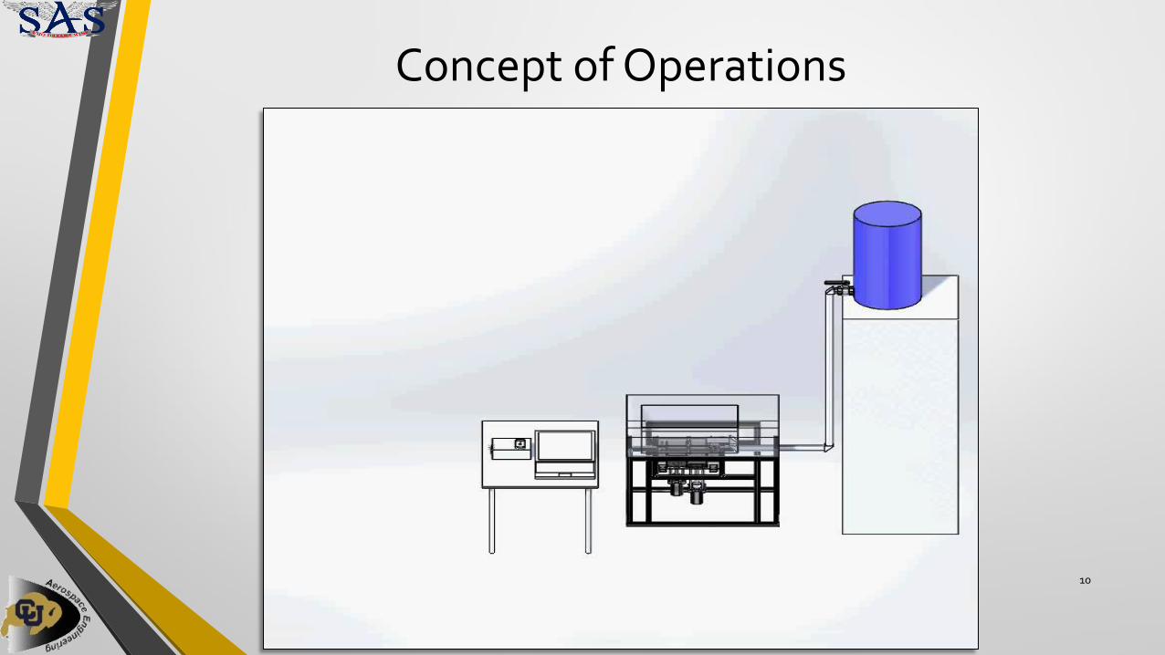
Project Concept of Operations
9
Sinter multiple layers of Sucrose/KNO3 powder using SLS
Slew Rate
Laser Power
Laser Cutter Powder Bed Material Property Testing
Solid Rocket Motor
Grain Geometry Powdered Propellant
Data Hardware Material Information
Background Design Applying
SLS Testing and
Results Summary
Concept of Operations
10

Background Design Applying
SLS Testing and
Results Summary
Levels of Success
11
Level Description Status
1.1 Design 3D Printing System for Sucrose-KNO3 Achieved
1.2 Characterize a Thermal Model for Propellant Achieved
1.3 Use Analogous Method to form Solid Propellant Achieved
2.1 Compare Material Properties (Casted vs Printed) Not
Achieved
2.2 Print a Solid Rocket Motor Cylinder Achieved
3.1 Manufacture 5 Different Grain Shapes Not
Achieved

Background Design Applying
SLS Testing and
Results Summary
Critical Project Elements
12
CPE Description
Laser Sintering Sucrose and KNO3
Powder Bed
Material Property Testing
• Verify Thermal Model and Laser Energy Control
• Component Integration and Tolerance Verification
• Full Powder Bed Cycle Test
• Validate Material Properties Between Casted and Printed Motors

Design Components and their functions
13
Background Design Applying
SLS Testing and
Results Summary

Components
Laser cutter
Powder bed system
Aluminum frame
Critical project elements before full integration

15
Powder Bed Design
• Acrylic Body
• Rake System • Stepper motor and plastic wedge flatten
powder and move it to the sintering region
• Gutter System • Acrylic body designed to keep water and
powder away from the electronics
• Pistons • Stepper motors provide vertical motion

Powder Bed Full Cycle
16
Pistons move propellant into path of rake
Supply Bed Sintering region
Rake sweeps propellant to sintering region

Background Design Applying
SLS Testing and
Results Summary
Laser Cutter
Full Spectrum H-Series 5G Laser Cutter
17
Laser Tube Air Exhaust Vent Mirror A
Mirror B
Mirror C Focusing Lens (X-Y) Movable Gantry Control Panel
Linear Rail
Motor
Drive Belt

Background Design Applying
SLS Testing and
Results Summary
Laser Cutter and Powder Bed Integration
18

Laser Cutter and Powder Bed Integration
• Laser cutter resting on top of aluminum frame
• Powder bed system resting inside the laser cutter and on the aluminum frame
• Aluminum frame holding up the laser cutter and powder bed
Applying SLS How to sinter rocket propellant
20
Background Design Applying
SLS Testing and
Results Summary

Background Design Applying
SLS Testing and
Results Summary
Sugar Sintering: Overview
21
Initial Sucrose Sintering Model: • Sucrose only model because
absorbs > 90% of the laser heat
• Predicts layer depth (mm) based on laser power (%) and slew rate (%)
Expected Results: • Sintering depth increases with
slower speed and higher power
• Temperatures spike well above auto ignition with higher energy output

Background Design Applying
SLS Testing and
Results Summary
Sugar Sintering: Results
22
Results: • Most samples thicker than
predicted • Likely caused by size of sugar
granules • Minimum Sintering Depth • Inaccurate (>1 Std) at Power < 5%
• Caused by heat conduction
Future Analysis: • Test goodness of fit (X^2) • Update model with minimum
thickness • Calibrate fit
Predicted Vs. Measured Sintering Depths [mm]

Background Design Applying
SLS Testing and
Results Summary
23
Before calibration
After calibration
Sugar Sintering: Calibration

Background Design Applying
SLS Testing and
Results Summary
24
Propellant Thermal Model: • Matched calibrated model to
within 5% error • Model validated with sintering
of sucrose-potassium nitrate Sintering Results:
• Sintering depths did not change by more than 0.5 mm
• Provided proof of concept for sintering propellant
Teal grid shows estimated sintering depths and the red dot marks the
tested depth of propellant
Propellant Thermal Model Predicted Propellant Sintering Depths [mm]
Propellant Sintering Model

Testing and Results How much have we accomplished?
25
Background Design Applying
SLS Testing and
Results Summary

Background Design Applying
SLS Testing and
Results Summary
Propellant Sintering Preliminary Results
• Proof of concept
o SLS manufacturing of solid propellant is possible
• We sintered four ~.035” layers of propellant in a cylindrical grain for a total motor length of .130”
26
First Ever 3D Printed Solid Rocket Motor

Background Design Applying
SLS Testing and
Results Summary
Propellant Sintering Preliminary Results
27
Solid Rocket Motor Printing Powder Bed Sweeping New Layer of Propellant

Summary Recap and future work
28
Background Design Applying
SLS Testing and
Results Summary

Background Design Applying
SLS Testing and
Results Summary
Future Work
• Dynamic Grains
o Pseudo-throttling
• Next iteration
o More robust sensors
o Non-destructive safety system
o Larger safety margin before ignition
• Motor performance testing
o Printed motor will have to withstand substantial vibrational loading before 3D printing can be considered a viable alternative in industry
29

Background Design Applying
SLS Testing and
Results Summary
Acknowledgements
30
Team SPAM would like to thank everyone who made this project possible: -Special Aerospace Services -Dr. Ryan Starkey -CU Boulder Aerospace PAB -Ifuzion 3D Printing -Andreas Bastian (OpenSLS) -Richard Nakka Rocketry -Frontier Astronautics

References
• 1Braeunig, Robert A. “Space Pictures”. Rocket and Space Technology. Accessed October 2015. Available:
• http://www.braeunig.us/space/pics/fig1-14.gif
• 2”Saltpetre”. The Ingredient Store.com Accessed October 2015. Available: http://store.theingredientstore.com/saltpetre-food-gradepotassiumnitrate.aspx
• 3“Sucrose Advanced Inorganics”. India Mart. Accessed October 2015. Available: http://dir.indiamart.com/impcat/sucrose-powder.html
• 4Miller, E., “Rapid Prototyping Technology Animations,” PADT, Inc Available: http://www.padtinc.com/blog/the-rp-resource/rapid-prototyping-technology-animations
• 5“Selective Laser Sintering (SLS),” MakeAGif Available: http://makeagif.com/cpjtel
• 6Sher, D., “Using SnowWhite to Laser Sinter Sugar,” 3D Printing Industry Available: http://3dprintingindustry.com/2014/09/26/sharebot-used-snowwhite-laser-sinter-sugar-worked-perfectly/.
• 7“Selective Laser Sugar Snowflakes,” Collected Edition Available: http://blog.collected-edition.com/post/41556924865/slssnowflakes.
• 8“EngArc - L - Stress-Strain Diagram,” EngArc - L - Stress-Strain Diagram Available: http://www.engineeringarchives.com/les_mom_stressstraindiagram.html.
• 9“Fracture Toughness,” Fracture Toughness Available: https://www.nde-ed.org/educationresources/communitycollege/materials/mechanical/fracturetoughness.htm.
• 10“Part 3: How to Build a High Power Rocket - Casting the Fuel into BATES Grains,” YouTube Available: https://www.youtube.com/watch?v=dfrnimt2bu4
• 11“HD How to make & cast R-Candy Fuel ( BEST RESULTS ),” YouTube Available: https://www.youtube.com/watch?v=uhm7nrv3bs8
31

References
• 12“Sucrose,” National Institute of Standards and Technology Available: http://webbook.nist.gov/cgi/cbook.cgi?id=c57501&mask=80
• 13“AC110V 1’ Solid Coil Electric Solenoid Valve Gas Water Fuels Air Solid Coil,” Amazon Available: http://www.amazon.com/ac110v-solid-electric-solenoid-valve/dp/b00lap0cie/ref=pd_sim_60_21?ie=utf8&refrid=1wa1qjzcp57mkscsykh7
• 14Shoberg, R., “Engineering Fundamentals of Threaded Fastener Design and Analysis”. PCB Load & Torque, Inc. Accessed Oct. 2015. Available: http://www.hexagon.de/rs/engineering%20fundamentals.pdf
• 15“Dissecting the Nut Factor”. Archetype Joint. Accessed Oct. 2015. Available: http://archetypejoint.com/?page_id=135
• 16“Joint1.gif”. Bolt Science. Accessed Oct. 2015. Available: http://www.boltscience.com/pages/nutorbolttightening.htm
• 17Herder, G., Weterings, F. P., and de Klerk, W. P. C., “MECHANICAL ANALYSIS ON ROCKET PROPELLANTS,” Journal of Thermal Analysis and Calorimetry, vol. 72, 2003, pp. 921–929. 18“Stereolighography,” Wikipedia Available: https://en.wikipedia.org/wiki/stereolithography. 19“Testing – Testing?,” IMPRESS Education: Mechanical Properties, Testing Available: http://www.spaceflight.esa.int/impress/text/education/mechanical properties/testing.html. 20Tussiwand, G. S., Saouma, V., Terzenbach, R., and Luca, L. D., “Fracture Mechanics of Composite Solid Rocket Propellant Grains: Material Testing,” Journal of Propulsion and Power, pp. 60–73. 21Bastian, Andreas. “R2 Final Assembly”. RepRap Wiki. Open Source CAD Files. Modified 7 December 2013. Accessed October 2015. Available: http://reprap.org/wiki/File:R2_final_assembly.png
• 22Kodikara, J., “Tensile strength of clay soils,” Tensile strength of clay soils Available: http://eng.monash.edu.au/civil/research/centres/geomechanics/cracking/tensile-clay.html
• 23“What is a Creep Test?,” What is a Creep Test? Available: http://www.wmtr.com/en.whatisacreeptest.html .
• 24Jacobsson, L., and Flansbjer, M., “Uniaxial compression tests,” Uniaxial compression tests Available: http://www.sp.se/en/index/services/rockmechanicaltesting/uniaxial/sidor/default.aspx .
• 25Full Spectrum Laser, “Hardware Setup and Operation,” FSL 40w Hobby Laser Manual
• 26 Laser Institute of America, “American National Standard for Safe Use of Lasers,” ANSI Z136.1, published 2007
• 27 Occupational Safety & Health Administration, “Laser Hazards,” OSHA Technical Manual, Section III: Chapter 6
• 28 CU Boulder Environmental Health and Safety, “Hazardous Materials & Waste Management,” http://ehs.colorado.edu/about/hazardous-materials-and-waste-management/ [retrieved 15 November 2015]
• 29 National Fire Protection Agency, “NFPA 704: Standard System for the Identification of the Hazards of Materials for Emergency Response,” http://www.nfpa.org/codes-and-standards/document-information-pages?mode=code&code=704 [retrieved 20 November 2015]
32

33
Questions?