Embed Size (px)
Citation preview

Solid Oxide Fuel Cell and PowerSolid Oxide Fuel Cell and Power S t D l t t PNNLS t D l t t PNNLSystem Development at PNNLSystem Development at PNNL
Larry Chick Energy Materials Group Pacific Northwest National LaboratoryPacific Northwest National Laboratory March 29 2011
ContentContent
Development of SOFCDevelopment of SOFC TTechnologyechnology
Fuel Reforming and System DesignFuel Reforming and System Design
Power andPower and EfficiencyEfficiency
2
Development of SOFCDevelopment of SOFC TTechnologyechnology
Fuel Reforming and System DesignFuel Reforming and System Design
Power andPower and EfficiencyEfficiency
3
t t
SOFC Technology Development at PNNL PNNL is the leading US DOE laboratory for SOFC research and development
Active in SOFC development since 1987 O $100 f SO C f 1999Over $100M of SOFC-related funding since 1999 Mostly DOE Office of Fossil Energy Solid State Energy Conversion Alliance (SECA)
PNNL developed anode-supported thin electrolyte technology
Transferred technology to Delphi Corp starting in 2000
Delphi is now supplying SOFC stacks for projects developingPNNLpower systems at PNNL
44
Solid Oxide Fuel Cell CharacteristicsSolid Oxide Fuel Cell Characteristics
High temperature (~700 ndash 800degC)
Can use H2 CO and CH4 as fuel so can run directly on reformed liquid hydrocarbons
Fuel must have very low sulfur levels (lt1 ppm to avoid performance loss))p
5
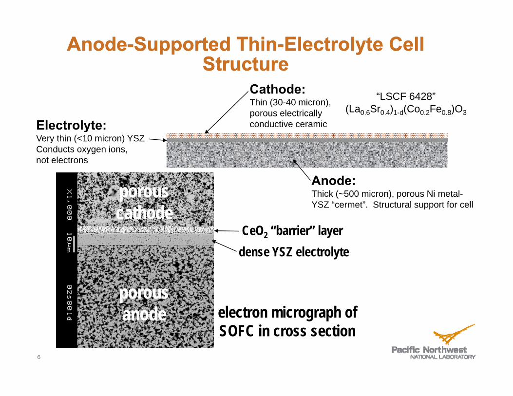
Anode Supported Thin--Electrolyte CellAnode--Supported Thin Electrolyte CellStructureStructure
Cathode ldquoLSCF 6428rdquoThin (30-40 micron) porous electrically (La06Sr04)1-d(Co02Fe08)O3
conductive ceramicconductive ceramic ElectrolyteElectrolyte Very thin (lt10 micron) YSZ Conducts oxygen ions not electrons
Anode Thick (~500 micron) porous Ni metal-YSZ ldquocermetrdquo Structural support for cell
CeO2 ldquobarrierrdquo layer dense YSZ electrolyte
electron micrograph of SOFC in cross section
porousporous cathodecathode
porousporous anodeanode
6
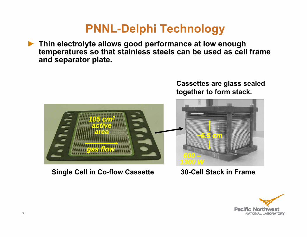
PNNL-Delphi Technology Thin electrolyte allows good performance at low enoughThin electrolyte allows good performance at low enough temperatures so that stainless steels can be used as cell frame and separator plate
Cassettes are glass sealed together to form stack
105 cm105 cm22
activeactive areaarea 6 56 5
gas flowgas flow
areaarea ~65 cm~65 cm
600600 ndashndash 1300 W1300 W
Single Cell in Co-flow Cassette 1300 W1300 W 30-Cell Stack in Frame
7
--
D
PNNL-Delphi SECA Team 228 cm8 cm22
3434 cc mm22 GenGen 22 101066 cmcm 22 AcActivtivee ArAr eeaa GenGen 44 404033 cmcm 22 AcActivtivee ArAr eeaaGeGenn 33
CeCellll ButtButtoonn
101055 cc mm22 ActActiivvee AreAre aa CeCellll Feb 20Feb 200000 -p-preresensentt Intermediate-Intermediate-ScaScallee
NNoovv 2020 0101 --ppreresseenntt
JanJan 22000202JanJan 202000 202022 003320200033
n 2 SystDelp July 20July 200033 --Delphh n 2 SystememiDelphiiDelphi GGGG eeeen 2n 2 SySystemstem
DelDelDelDelpppphihihihipppp GeGenGe 3n 33n 3 AAAAPPPPGen UUUU
JJuunnee 2020 0808 --
DDec 20ec 200022
JJuunnee 2020 0808
DeDellpphhiDPS3000-
i DPS3000-D
8
Delphirsquos First Commercial Market APU for Longg-Haul Trucks
bull Supports ldquohotel loadrdquo so ICU can be shut down at night
bull APU is started up on Monday morning shut down Friday night 9
Delphi Stack Performance S
tack
Vol
tagge
(V)
9700 hours Total degradation is 112 per 500 hours Degradation mechanism during initial 1000 hours and after 5000 hours is
MG735C805 - 30plus3 Dates 7312009 to 9232010 Fuel 485H2-485N2-3H20 Flows 325(A) 148(C) understood and design solutions are being implemented
Stack Voltage and Power Density for Constant Current Test
3030
25
20
15
10
55
0
000 100000 200000 300000 400000 500000 600000 700000 800000 900000 1000000
Time (Hours)
10
Delphi Stack Performance Stack endured 200 thermal cycles with minimal degradation
Flow condition changed
Stack Moved to another stand Loadbank replaced
for calibration
0 10 20 30 40 50 60 70 80 90 100 110 120 130 140 150 160 170 180 190 200 210
Thermal Cycle Number
11
1
09
08
07
06
05
0 404
03
02
01
00
Voolta
ge (V
olts
)
Development of SOFCDevelopment of SOFC TTechnologyechnology
Fuel Reforming and System DesignFuel Reforming and System Design
Power andPower and EfficiencyEfficiency
12
Hydro Desulfurization TechnologyechnologyHydro--Desulfurization Tfrac34 Funded byy Arm yy TARDEC
frac34 Brass board transportable system
frac34 Ran 10 kW PEM fuel cell
frac34 Demonstrated on JP-8 with 2750 ppm sulfur bull Very similar to Jet A but higher sulfur bull Could use JP-5 bull Bunker fuel would be problematicBunker fuel would be problematic
13
desu u at o
ConceptualFlow Diaggram to IntegrateHydro-desulfuration with SOFC Power System
Recycle Pump
~150C
HX
Recuperator
Heat Rejection
Purge
SOFC POWER MODULE
Water Recovery
Exhaust
SOFC Stack
Anode
Adiabatic Reformer Desulfurized Fuel
Electric Power
~1psi
Recovery
To HDS Reformer
HX
Cathode
Recuperator
Exhaust Air
p
Air
Reformate +H2S Burner
HDS DESULFURIZATION MODULE
Microchannel Steam Reformer
Reformate Based Hydrodesulfurization
To SOFC Power Module
Reformate
270 psig
~10
Desulfurized JP-8 Tank
JP-8
3000ppm max ~90 Desulfurized JP-8
003 ppmw max
14
e o ee o e
LiquidLiquid HCHC800degC
SteamSteam ReformerReformer
HeatHeat
SOFCSOFC StackStack
Efficiency Boost from Steam Reforming
bull Steam reforming is endothermic
H t f SOFC t k ibull Heat from SOFC stack is converted into ~25 increased chemical energy of reformate
Steam Reformation of n-Dodecane C12H26 + 12H2O + heatAElig 12CO + 25H2
bull SystemSystem yieldsyields gt60gt60 netnet eefffficiencyiciency
7552 9421 and Steamand Steam kJmole kJmole (125)
ldquoEnrichedrdquo SOFCldquoEnrichedrdquo SOFC FuelFuel GasGas SystemSystem yieldsyields gt60gt60 netnet efefficiencyficiency
bull Steam and heat for reforming obtained from SOFC stack exhaust
15
Partial Oxidation (POx)Partial Oxidation (POx) ReformingReforming
bull Some systems use POx reforming
bullbull POx is exothermicPOx is exothermic
bull POx reformate has less chemical energy than original fuel
bull Example dodecane C 12H26 + 6O2 = 12CO + 13H2 + heat
7552 6618 kJmole kJmole (87)
16
SOFC Power System with Steam Reformingg and Anode Recyycle
~650degC 15
~800degC
Adiabatic Steam
Reformer
85
17
SOFCSOFCStacksStacks
TRL 4 Demonstration System with Steamwith SteamTRL--4 Demonstration SystemReformingReforming andand AAnodenode RecycleRecycleReformingReforming andand AnodeAnode RecycleRecycle
cathodecathode recuperatorsrecuperators
steamsteam reformerreformer recuperatorsrecuperators reformerreformer
18
Development of SOFCDevelopment of SOFC TTechnologyechnology
Fuel Reforming and System DesignFuel Reforming and System Design
Power andPower and EfficiencyEfficiency
19
Higher Power DensityHigher Power DensityComes with Lower EfficiencyComes with Lower Efficiency
12 70
Electrical Stack Only
08
10c
m2)
60
Effic
ienc
y
Electric Power
Conversion Efficiency
0 4
06
wer
Den
sity
(W
50
al C
onve
rsio
n
02
04
Pow
40
Elec
trica
00 04 05 06 07 08
Volts per Cell
30
20
Factors Affecting Power Density (StackFactors Affecting Power Density (StackSiSi ))SiSizeze))
Voltagge
Temperature
Pressure
Concentration of H CO and CH in anode gas (reformate)Concentration of H2 CO and CH4 in anode gas (reformate)
Cell materials
21
Electrochemical ActivitElectrochemical Activityyyy is About to Im pproverovepp
16
1 0
12
14 Wcm
2 )
750degC 485 H2 3 H2O balance N2
06
08
10
wer
Den
sity
(W
New Electrode Materials
0 0
02
04Pow
Current Electrode Materials
00
07 08 09 10 11 Cell Voltage (V)
22
787 is a More Electric Airplane (MEA)
Efficiency changes in 787 due to Composite airframe Efficient no bleed engines Efficient no-bleed engines
Transition in power sources in theMEA
Increase in electric power to ~1 MWIncrease in electric power to ~1 MW
Efficient No-Bleed Engines 23
Anode Recycle Steam Reformer System withAnode Recycle Steam Reformer System with CompressorExpanderCompressorExpander
70 net efficiency at70 net efficiency at 8 atm and 08 Vcell
24
Back Up SlidesBack--Up Slides
25
Solid Electrolyte
When Y(3+) is substituted into ZrO2 frac34 The material is called yttria-stabilized zirconia (YSZ) because the substitution ldquolocksrdquo the material into the cubic structure the substitution locks the material into the cubic structure frac34 For every two yttrium ions one oxygen vacancy is created frac34 The oxygen vacancies facilitate ionic conductivity thermally actitivatted oxygen iions can ldquohoprdquo f rdquo from vacancy tto vacancy d ldquoh
cm
)
8 mole Y2O3 in ZrO2
nduc
tivity
(S
8 mole Y2O3 in ZrO2
O 2
Vac
oxygen
Ioni
c C
on
Temperature (degC)
O-2 Vac
oxygen vacancy
26
Zr+4Y+3
frac34
=
Solid Electrolyte
frac34Every modern car contains a solid oxide cell in the form of a zirconia oxygen sensor frac34The output voltage is governed by the Nernst equation
RT PO2 (air )Voltage = lnlnVoltage 4F PO2 (exhaust )
frac34Current is near zero
27
SOFC Schematic
hydrogenhydrogenH2 andor COhydrogenhydrogeny g
oxygenions
y g
oxygenions
2y g
oxygenions
y g
waterions
waterions
H2O andor CO2waterions
water
electron flowelectron flowelectron flowelectron flow
l i l l
dl i l l
dl i l l
dl i l l
d
oxygen
electrical load
oxygen
electrical load
oxygen
electrical load
oxygen
electrical load
H2 andor COygygygyg
oxygen ions
2
ions H2O andor CO2
cathodecathodecathodecathode eeeelllleeeecccc anodetrolyte anodetrolytetrolytetrolyte anodeanode catalyzescatalyzes catalyzescatalyzes
frac12frac12 OOfrac12frac12 22OO + 2+ 222 ee++ --2e2e IcircIcirc OO== + H+ HOO 22IcircIcirc HH22O + 2O + 2ee-shyIcircIcirc OOOO == ++ HH22IcircIcirc HH22OO ++ 2e2e and Oand O== + C+ COOIcircIcirc COCO22 + 2e+ 2e-shy
28
Upper Limit for Steel Framed Planar SOFCUpper Limit for Steel Framed Planar SOFCTechnology ~850Technology ~850degdegCC
18 Fuel
1 2
14
16
820degC
H2 076 CO 014
H2O 005 CO2 001 CH4 003
(Mole Fraction)
08
10
12
r Den
sity
(Wc
m2 )
04
06Pow
er
735degC
650degC
00
02
04 05 06 07 08 09 10 11
Cell Voltage (V)
650degC
Cell Voltage (V)
29
Effect of Pressure on SOFC PowerEffect of Pressure on SOFC Power DD iittDDensensitityy
14
10
12 W
cm
2)
06
08
wer
Den
sity
(W
Model Results 750degC
0 0
02
04Pow 750degC
Steam RecycleReformate
00 0 1 2 3 4 5 6 7 8 9 10
System Pressure (Atm)
30
Reformate Gives Lower PowerReformate Gives Lower Power than Moist Hydrogenthan Moist Hydrogen
12 B th t 800degC hi h f l fl tBoth at 800degC high fuel flow rate
80 Recycle ReformateReformate 21 H2
31 H2O 16 CO 32 CO2
10 Common Test Fuel 49 H208 3 H2O
Balance N2
06
0 404
02
0 000
07 08 09 10 11 Cell Voltage (V)
Poweer
Den
sity
(Wcm
2 )
31
Delphi Generation 4Delphi Generation 4 SOFC TechnologySOFC Technology
Delphi Gen 4 Cassette 403 cm2 Active Area
Manifold load plate and 620 g current collectors = 335 kg
32
Predicted Effects of Pressure and Cell VoltagePredicted Effects of Pressure and Cell Voltage onon SystemSystem EfficiencyEfficiency andand SStacktack MassMassonon SystemSystem EfficiencyEfficiency andand StackStack MassMass
For SOFC System with Steam Reformer Anode Recycle and CompressorExpander
EfficiencyMass SOFC Cell Voltage
Pressure 085 080 075 070 08 atm 757455 713358 682168 641608 3 atm 754291 701933 661404 611120 8 atm 752959 701333 651034 61859
Efficiency = Net Electrical Energy Supplied to Bus LHV of KeroseneEfficiency = Net Electrical Energy Supplied to Bus LHV of Kerosene
Mass is for cassettes needed to generate 821 kW gross power
33
ContentContent
Development of SOFCDevelopment of SOFC TTechnologyechnology
Fuel Reforming and System DesignFuel Reforming and System Design
Power andPower and EfficiencyEfficiency
2
Development of SOFCDevelopment of SOFC TTechnologyechnology
Fuel Reforming and System DesignFuel Reforming and System Design
Power andPower and EfficiencyEfficiency
3
t t
SOFC Technology Development at PNNL PNNL is the leading US DOE laboratory for SOFC research and development
Active in SOFC development since 1987 O $100 f SO C f 1999Over $100M of SOFC-related funding since 1999 Mostly DOE Office of Fossil Energy Solid State Energy Conversion Alliance (SECA)
PNNL developed anode-supported thin electrolyte technology
Transferred technology to Delphi Corp starting in 2000
Delphi is now supplying SOFC stacks for projects developingPNNLpower systems at PNNL
44
Solid Oxide Fuel Cell CharacteristicsSolid Oxide Fuel Cell Characteristics
High temperature (~700 ndash 800degC)
Can use H2 CO and CH4 as fuel so can run directly on reformed liquid hydrocarbons
Fuel must have very low sulfur levels (lt1 ppm to avoid performance loss))p
5
Anode Supported Thin--Electrolyte CellAnode--Supported Thin Electrolyte CellStructureStructure
Cathode ldquoLSCF 6428rdquoThin (30-40 micron) porous electrically (La06Sr04)1-d(Co02Fe08)O3
conductive ceramicconductive ceramic ElectrolyteElectrolyte Very thin (lt10 micron) YSZ Conducts oxygen ions not electrons
Anode Thick (~500 micron) porous Ni metal-YSZ ldquocermetrdquo Structural support for cell
CeO2 ldquobarrierrdquo layer dense YSZ electrolyte
electron micrograph of SOFC in cross section
porousporous cathodecathode
porousporous anodeanode
6
PNNL-Delphi Technology Thin electrolyte allows good performance at low enoughThin electrolyte allows good performance at low enough temperatures so that stainless steels can be used as cell frame and separator plate
Cassettes are glass sealed together to form stack
105 cm105 cm22
activeactive areaarea 6 56 5
gas flowgas flow
areaarea ~65 cm~65 cm
600600 ndashndash 1300 W1300 W
Single Cell in Co-flow Cassette 1300 W1300 W 30-Cell Stack in Frame
7
--
D
PNNL-Delphi SECA Team 228 cm8 cm22
3434 cc mm22 GenGen 22 101066 cmcm 22 AcActivtivee ArAr eeaa GenGen 44 404033 cmcm 22 AcActivtivee ArAr eeaaGeGenn 33
CeCellll ButtButtoonn
101055 cc mm22 ActActiivvee AreAre aa CeCellll Feb 20Feb 200000 -p-preresensentt Intermediate-Intermediate-ScaScallee
NNoovv 2020 0101 --ppreresseenntt
JanJan 22000202JanJan 202000 202022 003320200033
n 2 SystDelp July 20July 200033 --Delphh n 2 SystememiDelphiiDelphi GGGG eeeen 2n 2 SySystemstem
DelDelDelDelpppphihihihipppp GeGenGe 3n 33n 3 AAAAPPPPGen UUUU
JJuunnee 2020 0808 --
DDec 20ec 200022
JJuunnee 2020 0808
DeDellpphhiDPS3000-
i DPS3000-D
8
Delphirsquos First Commercial Market APU for Longg-Haul Trucks
bull Supports ldquohotel loadrdquo so ICU can be shut down at night
bull APU is started up on Monday morning shut down Friday night 9
Delphi Stack Performance S
tack
Vol
tagge
(V)
9700 hours Total degradation is 112 per 500 hours Degradation mechanism during initial 1000 hours and after 5000 hours is
MG735C805 - 30plus3 Dates 7312009 to 9232010 Fuel 485H2-485N2-3H20 Flows 325(A) 148(C) understood and design solutions are being implemented
Stack Voltage and Power Density for Constant Current Test
3030
25
20
15
10
55
0
000 100000 200000 300000 400000 500000 600000 700000 800000 900000 1000000
Time (Hours)
10
Delphi Stack Performance Stack endured 200 thermal cycles with minimal degradation
Flow condition changed
Stack Moved to another stand Loadbank replaced
for calibration
0 10 20 30 40 50 60 70 80 90 100 110 120 130 140 150 160 170 180 190 200 210
Thermal Cycle Number
11
1
09
08
07
06
05
0 404
03
02
01
00
Voolta
ge (V
olts
)
Development of SOFCDevelopment of SOFC TTechnologyechnology
Fuel Reforming and System DesignFuel Reforming and System Design
Power andPower and EfficiencyEfficiency
12
Hydro Desulfurization TechnologyechnologyHydro--Desulfurization Tfrac34 Funded byy Arm yy TARDEC
frac34 Brass board transportable system
frac34 Ran 10 kW PEM fuel cell
frac34 Demonstrated on JP-8 with 2750 ppm sulfur bull Very similar to Jet A but higher sulfur bull Could use JP-5 bull Bunker fuel would be problematicBunker fuel would be problematic
13
desu u at o
ConceptualFlow Diaggram to IntegrateHydro-desulfuration with SOFC Power System
Recycle Pump
~150C
HX
Recuperator
Heat Rejection
Purge
SOFC POWER MODULE
Water Recovery
Exhaust
SOFC Stack
Anode
Adiabatic Reformer Desulfurized Fuel
Electric Power
~1psi
Recovery
To HDS Reformer
HX
Cathode
Recuperator
Exhaust Air
p
Air
Reformate +H2S Burner
HDS DESULFURIZATION MODULE
Microchannel Steam Reformer
Reformate Based Hydrodesulfurization
To SOFC Power Module
Reformate
270 psig
~10
Desulfurized JP-8 Tank
JP-8
3000ppm max ~90 Desulfurized JP-8
003 ppmw max
14
e o ee o e
LiquidLiquid HCHC800degC
SteamSteam ReformerReformer
HeatHeat
SOFCSOFC StackStack
Efficiency Boost from Steam Reforming
bull Steam reforming is endothermic
H t f SOFC t k ibull Heat from SOFC stack is converted into ~25 increased chemical energy of reformate
Steam Reformation of n-Dodecane C12H26 + 12H2O + heatAElig 12CO + 25H2
bull SystemSystem yieldsyields gt60gt60 netnet eefffficiencyiciency
7552 9421 and Steamand Steam kJmole kJmole (125)
ldquoEnrichedrdquo SOFCldquoEnrichedrdquo SOFC FuelFuel GasGas SystemSystem yieldsyields gt60gt60 netnet efefficiencyficiency
bull Steam and heat for reforming obtained from SOFC stack exhaust
15
Partial Oxidation (POx)Partial Oxidation (POx) ReformingReforming
bull Some systems use POx reforming
bullbull POx is exothermicPOx is exothermic
bull POx reformate has less chemical energy than original fuel
bull Example dodecane C 12H26 + 6O2 = 12CO + 13H2 + heat
7552 6618 kJmole kJmole (87)
16
SOFC Power System with Steam Reformingg and Anode Recyycle
~650degC 15
~800degC
Adiabatic Steam
Reformer
85
17
SOFCSOFCStacksStacks
TRL 4 Demonstration System with Steamwith SteamTRL--4 Demonstration SystemReformingReforming andand AAnodenode RecycleRecycleReformingReforming andand AnodeAnode RecycleRecycle
cathodecathode recuperatorsrecuperators
steamsteam reformerreformer recuperatorsrecuperators reformerreformer
18
Development of SOFCDevelopment of SOFC TTechnologyechnology
Fuel Reforming and System DesignFuel Reforming and System Design
Power andPower and EfficiencyEfficiency
19
Higher Power DensityHigher Power DensityComes with Lower EfficiencyComes with Lower Efficiency
12 70
Electrical Stack Only
08
10c
m2)
60
Effic
ienc
y
Electric Power
Conversion Efficiency
0 4
06
wer
Den
sity
(W
50
al C
onve
rsio
n
02
04
Pow
40
Elec
trica
00 04 05 06 07 08
Volts per Cell
30
20
Factors Affecting Power Density (StackFactors Affecting Power Density (StackSiSi ))SiSizeze))
Voltagge
Temperature
Pressure
Concentration of H CO and CH in anode gas (reformate)Concentration of H2 CO and CH4 in anode gas (reformate)
Cell materials
21
Electrochemical ActivitElectrochemical Activityyyy is About to Im pproverovepp
16
1 0
12
14 Wcm
2 )
750degC 485 H2 3 H2O balance N2
06
08
10
wer
Den
sity
(W
New Electrode Materials
0 0
02
04Pow
Current Electrode Materials
00
07 08 09 10 11 Cell Voltage (V)
22
787 is a More Electric Airplane (MEA)
Efficiency changes in 787 due to Composite airframe Efficient no bleed engines Efficient no-bleed engines
Transition in power sources in theMEA
Increase in electric power to ~1 MWIncrease in electric power to ~1 MW
Efficient No-Bleed Engines 23
Anode Recycle Steam Reformer System withAnode Recycle Steam Reformer System with CompressorExpanderCompressorExpander
70 net efficiency at70 net efficiency at 8 atm and 08 Vcell
24
Back Up SlidesBack--Up Slides
25
Solid Electrolyte
When Y(3+) is substituted into ZrO2 frac34 The material is called yttria-stabilized zirconia (YSZ) because the substitution ldquolocksrdquo the material into the cubic structure the substitution locks the material into the cubic structure frac34 For every two yttrium ions one oxygen vacancy is created frac34 The oxygen vacancies facilitate ionic conductivity thermally actitivatted oxygen iions can ldquohoprdquo f rdquo from vacancy tto vacancy d ldquoh
cm
)
8 mole Y2O3 in ZrO2
nduc
tivity
(S
8 mole Y2O3 in ZrO2
O 2
Vac
oxygen
Ioni
c C
on
Temperature (degC)
O-2 Vac
oxygen vacancy
26
Zr+4Y+3
frac34
=
Solid Electrolyte
frac34Every modern car contains a solid oxide cell in the form of a zirconia oxygen sensor frac34The output voltage is governed by the Nernst equation
RT PO2 (air )Voltage = lnlnVoltage 4F PO2 (exhaust )
frac34Current is near zero
27
SOFC Schematic
hydrogenhydrogenH2 andor COhydrogenhydrogeny g
oxygenions
y g
oxygenions
2y g
oxygenions
y g
waterions
waterions
H2O andor CO2waterions
water
electron flowelectron flowelectron flowelectron flow
l i l l
dl i l l
dl i l l
dl i l l
d
oxygen
electrical load
oxygen
electrical load
oxygen
electrical load
oxygen
electrical load
H2 andor COygygygyg
oxygen ions
2
ions H2O andor CO2
cathodecathodecathodecathode eeeelllleeeecccc anodetrolyte anodetrolytetrolytetrolyte anodeanode catalyzescatalyzes catalyzescatalyzes
frac12frac12 OOfrac12frac12 22OO + 2+ 222 ee++ --2e2e IcircIcirc OO== + H+ HOO 22IcircIcirc HH22O + 2O + 2ee-shyIcircIcirc OOOO == ++ HH22IcircIcirc HH22OO ++ 2e2e and Oand O== + C+ COOIcircIcirc COCO22 + 2e+ 2e-shy
28
Upper Limit for Steel Framed Planar SOFCUpper Limit for Steel Framed Planar SOFCTechnology ~850Technology ~850degdegCC
18 Fuel
1 2
14
16
820degC
H2 076 CO 014
H2O 005 CO2 001 CH4 003
(Mole Fraction)
08
10
12
r Den
sity
(Wc
m2 )
04
06Pow
er
735degC
650degC
00
02
04 05 06 07 08 09 10 11
Cell Voltage (V)
650degC
Cell Voltage (V)
29
Effect of Pressure on SOFC PowerEffect of Pressure on SOFC Power DD iittDDensensitityy
14
10
12 W
cm
2)
06
08
wer
Den
sity
(W
Model Results 750degC
0 0
02
04Pow 750degC
Steam RecycleReformate
00 0 1 2 3 4 5 6 7 8 9 10
System Pressure (Atm)
30
Reformate Gives Lower PowerReformate Gives Lower Power than Moist Hydrogenthan Moist Hydrogen
12 B th t 800degC hi h f l fl tBoth at 800degC high fuel flow rate
80 Recycle ReformateReformate 21 H2
31 H2O 16 CO 32 CO2
10 Common Test Fuel 49 H208 3 H2O
Balance N2
06
0 404
02
0 000
07 08 09 10 11 Cell Voltage (V)
Poweer
Den
sity
(Wcm
2 )
31
Delphi Generation 4Delphi Generation 4 SOFC TechnologySOFC Technology
Delphi Gen 4 Cassette 403 cm2 Active Area
Manifold load plate and 620 g current collectors = 335 kg
32
Predicted Effects of Pressure and Cell VoltagePredicted Effects of Pressure and Cell Voltage onon SystemSystem EfficiencyEfficiency andand SStacktack MassMassonon SystemSystem EfficiencyEfficiency andand StackStack MassMass
For SOFC System with Steam Reformer Anode Recycle and CompressorExpander
EfficiencyMass SOFC Cell Voltage
Pressure 085 080 075 070 08 atm 757455 713358 682168 641608 3 atm 754291 701933 661404 611120 8 atm 752959 701333 651034 61859
Efficiency = Net Electrical Energy Supplied to Bus LHV of KeroseneEfficiency = Net Electrical Energy Supplied to Bus LHV of Kerosene
Mass is for cassettes needed to generate 821 kW gross power
33

Development of SOFCDevelopment of SOFC TTechnologyechnology
Fuel Reforming and System DesignFuel Reforming and System Design
Power andPower and EfficiencyEfficiency
3
t t
SOFC Technology Development at PNNL PNNL is the leading US DOE laboratory for SOFC research and development
Active in SOFC development since 1987 O $100 f SO C f 1999Over $100M of SOFC-related funding since 1999 Mostly DOE Office of Fossil Energy Solid State Energy Conversion Alliance (SECA)
PNNL developed anode-supported thin electrolyte technology
Transferred technology to Delphi Corp starting in 2000
Delphi is now supplying SOFC stacks for projects developingPNNLpower systems at PNNL
44
Solid Oxide Fuel Cell CharacteristicsSolid Oxide Fuel Cell Characteristics
High temperature (~700 ndash 800degC)
Can use H2 CO and CH4 as fuel so can run directly on reformed liquid hydrocarbons
Fuel must have very low sulfur levels (lt1 ppm to avoid performance loss))p
5
Anode Supported Thin--Electrolyte CellAnode--Supported Thin Electrolyte CellStructureStructure
Cathode ldquoLSCF 6428rdquoThin (30-40 micron) porous electrically (La06Sr04)1-d(Co02Fe08)O3
conductive ceramicconductive ceramic ElectrolyteElectrolyte Very thin (lt10 micron) YSZ Conducts oxygen ions not electrons
Anode Thick (~500 micron) porous Ni metal-YSZ ldquocermetrdquo Structural support for cell
CeO2 ldquobarrierrdquo layer dense YSZ electrolyte
electron micrograph of SOFC in cross section
porousporous cathodecathode
porousporous anodeanode
6
PNNL-Delphi Technology Thin electrolyte allows good performance at low enoughThin electrolyte allows good performance at low enough temperatures so that stainless steels can be used as cell frame and separator plate
Cassettes are glass sealed together to form stack
105 cm105 cm22
activeactive areaarea 6 56 5
gas flowgas flow
areaarea ~65 cm~65 cm
600600 ndashndash 1300 W1300 W
Single Cell in Co-flow Cassette 1300 W1300 W 30-Cell Stack in Frame
7
--
D
PNNL-Delphi SECA Team 228 cm8 cm22
3434 cc mm22 GenGen 22 101066 cmcm 22 AcActivtivee ArAr eeaa GenGen 44 404033 cmcm 22 AcActivtivee ArAr eeaaGeGenn 33
CeCellll ButtButtoonn
101055 cc mm22 ActActiivvee AreAre aa CeCellll Feb 20Feb 200000 -p-preresensentt Intermediate-Intermediate-ScaScallee
NNoovv 2020 0101 --ppreresseenntt
JanJan 22000202JanJan 202000 202022 003320200033
n 2 SystDelp July 20July 200033 --Delphh n 2 SystememiDelphiiDelphi GGGG eeeen 2n 2 SySystemstem
DelDelDelDelpppphihihihipppp GeGenGe 3n 33n 3 AAAAPPPPGen UUUU
JJuunnee 2020 0808 --
DDec 20ec 200022
JJuunnee 2020 0808
DeDellpphhiDPS3000-
i DPS3000-D
8
Delphirsquos First Commercial Market APU for Longg-Haul Trucks
bull Supports ldquohotel loadrdquo so ICU can be shut down at night
bull APU is started up on Monday morning shut down Friday night 9
Delphi Stack Performance S
tack
Vol
tagge
(V)
9700 hours Total degradation is 112 per 500 hours Degradation mechanism during initial 1000 hours and after 5000 hours is
MG735C805 - 30plus3 Dates 7312009 to 9232010 Fuel 485H2-485N2-3H20 Flows 325(A) 148(C) understood and design solutions are being implemented
Stack Voltage and Power Density for Constant Current Test
3030
25
20
15
10
55
0
000 100000 200000 300000 400000 500000 600000 700000 800000 900000 1000000
Time (Hours)
10
Delphi Stack Performance Stack endured 200 thermal cycles with minimal degradation
Flow condition changed
Stack Moved to another stand Loadbank replaced
for calibration
0 10 20 30 40 50 60 70 80 90 100 110 120 130 140 150 160 170 180 190 200 210
Thermal Cycle Number
11
1
09
08
07
06
05
0 404
03
02
01
00
Voolta
ge (V
olts
)
Development of SOFCDevelopment of SOFC TTechnologyechnology
Fuel Reforming and System DesignFuel Reforming and System Design
Power andPower and EfficiencyEfficiency
12
Hydro Desulfurization TechnologyechnologyHydro--Desulfurization Tfrac34 Funded byy Arm yy TARDEC
frac34 Brass board transportable system
frac34 Ran 10 kW PEM fuel cell
frac34 Demonstrated on JP-8 with 2750 ppm sulfur bull Very similar to Jet A but higher sulfur bull Could use JP-5 bull Bunker fuel would be problematicBunker fuel would be problematic
13
desu u at o
ConceptualFlow Diaggram to IntegrateHydro-desulfuration with SOFC Power System
Recycle Pump
~150C
HX
Recuperator
Heat Rejection
Purge
SOFC POWER MODULE
Water Recovery
Exhaust
SOFC Stack
Anode
Adiabatic Reformer Desulfurized Fuel
Electric Power
~1psi
Recovery
To HDS Reformer
HX
Cathode
Recuperator
Exhaust Air
p
Air
Reformate +H2S Burner
HDS DESULFURIZATION MODULE
Microchannel Steam Reformer
Reformate Based Hydrodesulfurization
To SOFC Power Module
Reformate
270 psig
~10
Desulfurized JP-8 Tank
JP-8
3000ppm max ~90 Desulfurized JP-8
003 ppmw max
14
e o ee o e
LiquidLiquid HCHC800degC
SteamSteam ReformerReformer
HeatHeat
SOFCSOFC StackStack
Efficiency Boost from Steam Reforming
bull Steam reforming is endothermic
H t f SOFC t k ibull Heat from SOFC stack is converted into ~25 increased chemical energy of reformate
Steam Reformation of n-Dodecane C12H26 + 12H2O + heatAElig 12CO + 25H2
bull SystemSystem yieldsyields gt60gt60 netnet eefffficiencyiciency
7552 9421 and Steamand Steam kJmole kJmole (125)
ldquoEnrichedrdquo SOFCldquoEnrichedrdquo SOFC FuelFuel GasGas SystemSystem yieldsyields gt60gt60 netnet efefficiencyficiency
bull Steam and heat for reforming obtained from SOFC stack exhaust
15
Partial Oxidation (POx)Partial Oxidation (POx) ReformingReforming
bull Some systems use POx reforming
bullbull POx is exothermicPOx is exothermic
bull POx reformate has less chemical energy than original fuel
bull Example dodecane C 12H26 + 6O2 = 12CO + 13H2 + heat
7552 6618 kJmole kJmole (87)
16
SOFC Power System with Steam Reformingg and Anode Recyycle
~650degC 15
~800degC
Adiabatic Steam
Reformer
85
17
SOFCSOFCStacksStacks
TRL 4 Demonstration System with Steamwith SteamTRL--4 Demonstration SystemReformingReforming andand AAnodenode RecycleRecycleReformingReforming andand AnodeAnode RecycleRecycle
cathodecathode recuperatorsrecuperators
steamsteam reformerreformer recuperatorsrecuperators reformerreformer
18
Development of SOFCDevelopment of SOFC TTechnologyechnology
Fuel Reforming and System DesignFuel Reforming and System Design
Power andPower and EfficiencyEfficiency
19
Higher Power DensityHigher Power DensityComes with Lower EfficiencyComes with Lower Efficiency
12 70
Electrical Stack Only
08
10c
m2)
60
Effic
ienc
y
Electric Power
Conversion Efficiency
0 4
06
wer
Den
sity
(W
50
al C
onve
rsio
n
02
04
Pow
40
Elec
trica
00 04 05 06 07 08
Volts per Cell
30
20
Factors Affecting Power Density (StackFactors Affecting Power Density (StackSiSi ))SiSizeze))
Voltagge
Temperature
Pressure
Concentration of H CO and CH in anode gas (reformate)Concentration of H2 CO and CH4 in anode gas (reformate)
Cell materials
21
Electrochemical ActivitElectrochemical Activityyyy is About to Im pproverovepp
16
1 0
12
14 Wcm
2 )
750degC 485 H2 3 H2O balance N2
06
08
10
wer
Den
sity
(W
New Electrode Materials
0 0
02
04Pow
Current Electrode Materials
00
07 08 09 10 11 Cell Voltage (V)
22
787 is a More Electric Airplane (MEA)
Efficiency changes in 787 due to Composite airframe Efficient no bleed engines Efficient no-bleed engines
Transition in power sources in theMEA
Increase in electric power to ~1 MWIncrease in electric power to ~1 MW
Efficient No-Bleed Engines 23
Anode Recycle Steam Reformer System withAnode Recycle Steam Reformer System with CompressorExpanderCompressorExpander
70 net efficiency at70 net efficiency at 8 atm and 08 Vcell
24
Back Up SlidesBack--Up Slides
25
Solid Electrolyte
When Y(3+) is substituted into ZrO2 frac34 The material is called yttria-stabilized zirconia (YSZ) because the substitution ldquolocksrdquo the material into the cubic structure the substitution locks the material into the cubic structure frac34 For every two yttrium ions one oxygen vacancy is created frac34 The oxygen vacancies facilitate ionic conductivity thermally actitivatted oxygen iions can ldquohoprdquo f rdquo from vacancy tto vacancy d ldquoh
cm
)
8 mole Y2O3 in ZrO2
nduc
tivity
(S
8 mole Y2O3 in ZrO2
O 2
Vac
oxygen
Ioni
c C
on
Temperature (degC)
O-2 Vac
oxygen vacancy
26
Zr+4Y+3
frac34
=
Solid Electrolyte
frac34Every modern car contains a solid oxide cell in the form of a zirconia oxygen sensor frac34The output voltage is governed by the Nernst equation
RT PO2 (air )Voltage = lnlnVoltage 4F PO2 (exhaust )
frac34Current is near zero
27
SOFC Schematic
hydrogenhydrogenH2 andor COhydrogenhydrogeny g
oxygenions
y g
oxygenions
2y g
oxygenions
y g
waterions
waterions
H2O andor CO2waterions
water
electron flowelectron flowelectron flowelectron flow
l i l l
dl i l l
dl i l l
dl i l l
d
oxygen
electrical load
oxygen
electrical load
oxygen
electrical load
oxygen
electrical load
H2 andor COygygygyg
oxygen ions
2
ions H2O andor CO2
cathodecathodecathodecathode eeeelllleeeecccc anodetrolyte anodetrolytetrolytetrolyte anodeanode catalyzescatalyzes catalyzescatalyzes
frac12frac12 OOfrac12frac12 22OO + 2+ 222 ee++ --2e2e IcircIcirc OO== + H+ HOO 22IcircIcirc HH22O + 2O + 2ee-shyIcircIcirc OOOO == ++ HH22IcircIcirc HH22OO ++ 2e2e and Oand O== + C+ COOIcircIcirc COCO22 + 2e+ 2e-shy
28
Upper Limit for Steel Framed Planar SOFCUpper Limit for Steel Framed Planar SOFCTechnology ~850Technology ~850degdegCC
18 Fuel
1 2
14
16
820degC
H2 076 CO 014
H2O 005 CO2 001 CH4 003
(Mole Fraction)
08
10
12
r Den
sity
(Wc
m2 )
04
06Pow
er
735degC
650degC
00
02
04 05 06 07 08 09 10 11
Cell Voltage (V)
650degC
Cell Voltage (V)
29
Effect of Pressure on SOFC PowerEffect of Pressure on SOFC Power DD iittDDensensitityy
14
10
12 W
cm
2)
06
08
wer
Den
sity
(W
Model Results 750degC
0 0
02
04Pow 750degC
Steam RecycleReformate
00 0 1 2 3 4 5 6 7 8 9 10
System Pressure (Atm)
30
Reformate Gives Lower PowerReformate Gives Lower Power than Moist Hydrogenthan Moist Hydrogen
12 B th t 800degC hi h f l fl tBoth at 800degC high fuel flow rate
80 Recycle ReformateReformate 21 H2
31 H2O 16 CO 32 CO2
10 Common Test Fuel 49 H208 3 H2O
Balance N2
06
0 404
02
0 000
07 08 09 10 11 Cell Voltage (V)
Poweer
Den
sity
(Wcm
2 )
31
Delphi Generation 4Delphi Generation 4 SOFC TechnologySOFC Technology
Delphi Gen 4 Cassette 403 cm2 Active Area
Manifold load plate and 620 g current collectors = 335 kg
32
Predicted Effects of Pressure and Cell VoltagePredicted Effects of Pressure and Cell Voltage onon SystemSystem EfficiencyEfficiency andand SStacktack MassMassonon SystemSystem EfficiencyEfficiency andand StackStack MassMass
For SOFC System with Steam Reformer Anode Recycle and CompressorExpander
EfficiencyMass SOFC Cell Voltage
Pressure 085 080 075 070 08 atm 757455 713358 682168 641608 3 atm 754291 701933 661404 611120 8 atm 752959 701333 651034 61859
Efficiency = Net Electrical Energy Supplied to Bus LHV of KeroseneEfficiency = Net Electrical Energy Supplied to Bus LHV of Kerosene
Mass is for cassettes needed to generate 821 kW gross power
33
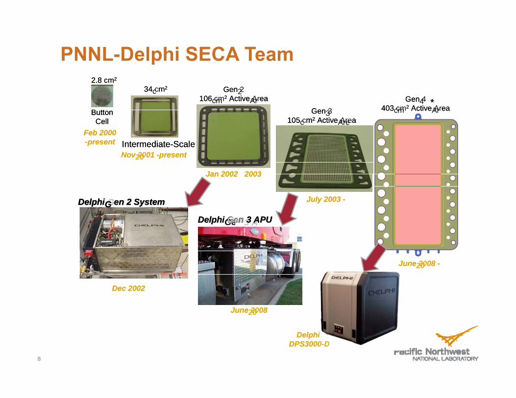
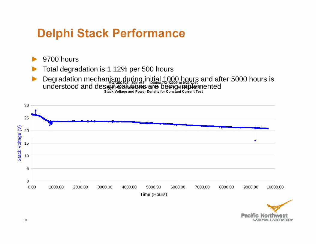
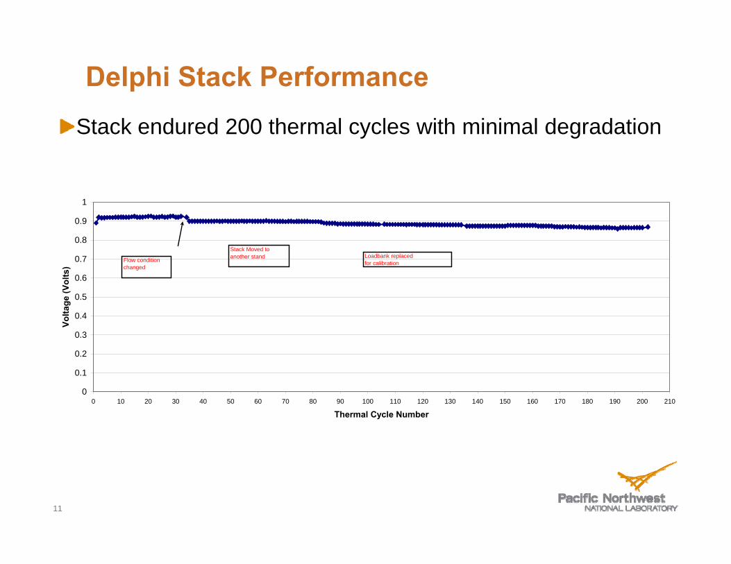

Development of SOFCDevelopment of SOFC TTechnologyechnology
Fuel Reforming and System DesignFuel Reforming and System Design
Power andPower and EfficiencyEfficiency
12
Hydro Desulfurization TechnologyechnologyHydro--Desulfurization Tfrac34 Funded byy Arm yy TARDEC
frac34 Brass board transportable system
frac34 Ran 10 kW PEM fuel cell
frac34 Demonstrated on JP-8 with 2750 ppm sulfur bull Very similar to Jet A but higher sulfur bull Could use JP-5 bull Bunker fuel would be problematicBunker fuel would be problematic
13
desu u at o
ConceptualFlow Diaggram to IntegrateHydro-desulfuration with SOFC Power System
Recycle Pump
~150C
HX
Recuperator
Heat Rejection
Purge
SOFC POWER MODULE
Water Recovery
Exhaust
SOFC Stack
Anode
Adiabatic Reformer Desulfurized Fuel
Electric Power
~1psi
Recovery
To HDS Reformer
HX
Cathode
Recuperator
Exhaust Air
p
Air
Reformate +H2S Burner
HDS DESULFURIZATION MODULE
Microchannel Steam Reformer
Reformate Based Hydrodesulfurization
To SOFC Power Module
Reformate
270 psig
~10
Desulfurized JP-8 Tank
JP-8
3000ppm max ~90 Desulfurized JP-8
003 ppmw max
14
e o ee o e
LiquidLiquid HCHC800degC
SteamSteam ReformerReformer
HeatHeat
SOFCSOFC StackStack
Efficiency Boost from Steam Reforming
bull Steam reforming is endothermic
H t f SOFC t k ibull Heat from SOFC stack is converted into ~25 increased chemical energy of reformate
Steam Reformation of n-Dodecane C12H26 + 12H2O + heatAElig 12CO + 25H2
bull SystemSystem yieldsyields gt60gt60 netnet eefffficiencyiciency
7552 9421 and Steamand Steam kJmole kJmole (125)
ldquoEnrichedrdquo SOFCldquoEnrichedrdquo SOFC FuelFuel GasGas SystemSystem yieldsyields gt60gt60 netnet efefficiencyficiency
bull Steam and heat for reforming obtained from SOFC stack exhaust
15
Partial Oxidation (POx)Partial Oxidation (POx) ReformingReforming
bull Some systems use POx reforming
bullbull POx is exothermicPOx is exothermic
bull POx reformate has less chemical energy than original fuel
bull Example dodecane C 12H26 + 6O2 = 12CO + 13H2 + heat
7552 6618 kJmole kJmole (87)
16
SOFC Power System with Steam Reformingg and Anode Recyycle
~650degC 15
~800degC
Adiabatic Steam
Reformer
85
17
SOFCSOFCStacksStacks
TRL 4 Demonstration System with Steamwith SteamTRL--4 Demonstration SystemReformingReforming andand AAnodenode RecycleRecycleReformingReforming andand AnodeAnode RecycleRecycle
cathodecathode recuperatorsrecuperators
steamsteam reformerreformer recuperatorsrecuperators reformerreformer
18
Development of SOFCDevelopment of SOFC TTechnologyechnology
Fuel Reforming and System DesignFuel Reforming and System Design
Power andPower and EfficiencyEfficiency
19
Higher Power DensityHigher Power DensityComes with Lower EfficiencyComes with Lower Efficiency
12 70
Electrical Stack Only
08
10c
m2)
60
Effic
ienc
y
Electric Power
Conversion Efficiency
0 4
06
wer
Den
sity
(W
50
al C
onve
rsio
n
02
04
Pow
40
Elec
trica
00 04 05 06 07 08
Volts per Cell
30
20
Factors Affecting Power Density (StackFactors Affecting Power Density (StackSiSi ))SiSizeze))
Voltagge
Temperature
Pressure
Concentration of H CO and CH in anode gas (reformate)Concentration of H2 CO and CH4 in anode gas (reformate)
Cell materials
21
Electrochemical ActivitElectrochemical Activityyyy is About to Im pproverovepp
16
1 0
12
14 Wcm
2 )
750degC 485 H2 3 H2O balance N2
06
08
10
wer
Den
sity
(W
New Electrode Materials
0 0
02
04Pow
Current Electrode Materials
00
07 08 09 10 11 Cell Voltage (V)
22
787 is a More Electric Airplane (MEA)
Efficiency changes in 787 due to Composite airframe Efficient no bleed engines Efficient no-bleed engines
Transition in power sources in theMEA
Increase in electric power to ~1 MWIncrease in electric power to ~1 MW
Efficient No-Bleed Engines 23
Anode Recycle Steam Reformer System withAnode Recycle Steam Reformer System with CompressorExpanderCompressorExpander
70 net efficiency at70 net efficiency at 8 atm and 08 Vcell
24
Back Up SlidesBack--Up Slides
25
Solid Electrolyte
When Y(3+) is substituted into ZrO2 frac34 The material is called yttria-stabilized zirconia (YSZ) because the substitution ldquolocksrdquo the material into the cubic structure the substitution locks the material into the cubic structure frac34 For every two yttrium ions one oxygen vacancy is created frac34 The oxygen vacancies facilitate ionic conductivity thermally actitivatted oxygen iions can ldquohoprdquo f rdquo from vacancy tto vacancy d ldquoh
cm
)
8 mole Y2O3 in ZrO2
nduc
tivity
(S
8 mole Y2O3 in ZrO2
O 2
Vac
oxygen
Ioni
c C
on
Temperature (degC)
O-2 Vac
oxygen vacancy
26
Zr+4Y+3
frac34
=
Solid Electrolyte
frac34Every modern car contains a solid oxide cell in the form of a zirconia oxygen sensor frac34The output voltage is governed by the Nernst equation
RT PO2 (air )Voltage = lnlnVoltage 4F PO2 (exhaust )
frac34Current is near zero
27
SOFC Schematic
hydrogenhydrogenH2 andor COhydrogenhydrogeny g
oxygenions
y g
oxygenions
2y g
oxygenions
y g
waterions
waterions
H2O andor CO2waterions
water
electron flowelectron flowelectron flowelectron flow
l i l l
dl i l l
dl i l l
dl i l l
d
oxygen
electrical load
oxygen
electrical load
oxygen
electrical load
oxygen
electrical load
H2 andor COygygygyg
oxygen ions
2
ions H2O andor CO2
cathodecathodecathodecathode eeeelllleeeecccc anodetrolyte anodetrolytetrolytetrolyte anodeanode catalyzescatalyzes catalyzescatalyzes
frac12frac12 OOfrac12frac12 22OO + 2+ 222 ee++ --2e2e IcircIcirc OO== + H+ HOO 22IcircIcirc HH22O + 2O + 2ee-shyIcircIcirc OOOO == ++ HH22IcircIcirc HH22OO ++ 2e2e and Oand O== + C+ COOIcircIcirc COCO22 + 2e+ 2e-shy
28
Upper Limit for Steel Framed Planar SOFCUpper Limit for Steel Framed Planar SOFCTechnology ~850Technology ~850degdegCC
18 Fuel
1 2
14
16
820degC
H2 076 CO 014
H2O 005 CO2 001 CH4 003
(Mole Fraction)
08
10
12
r Den
sity
(Wc
m2 )
04
06Pow
er
735degC
650degC
00
02
04 05 06 07 08 09 10 11
Cell Voltage (V)
650degC
Cell Voltage (V)
29
Effect of Pressure on SOFC PowerEffect of Pressure on SOFC Power DD iittDDensensitityy
14
10
12 W
cm
2)
06
08
wer
Den
sity
(W
Model Results 750degC
0 0
02
04Pow 750degC
Steam RecycleReformate
00 0 1 2 3 4 5 6 7 8 9 10
System Pressure (Atm)
30
Reformate Gives Lower PowerReformate Gives Lower Power than Moist Hydrogenthan Moist Hydrogen
12 B th t 800degC hi h f l fl tBoth at 800degC high fuel flow rate
80 Recycle ReformateReformate 21 H2
31 H2O 16 CO 32 CO2
10 Common Test Fuel 49 H208 3 H2O
Balance N2
06
0 404
02
0 000
07 08 09 10 11 Cell Voltage (V)
Poweer
Den
sity
(Wcm
2 )
31
Delphi Generation 4Delphi Generation 4 SOFC TechnologySOFC Technology
Delphi Gen 4 Cassette 403 cm2 Active Area
Manifold load plate and 620 g current collectors = 335 kg
32
Predicted Effects of Pressure and Cell VoltagePredicted Effects of Pressure and Cell Voltage onon SystemSystem EfficiencyEfficiency andand SStacktack MassMassonon SystemSystem EfficiencyEfficiency andand StackStack MassMass
For SOFC System with Steam Reformer Anode Recycle and CompressorExpander
EfficiencyMass SOFC Cell Voltage
Pressure 085 080 075 070 08 atm 757455 713358 682168 641608 3 atm 754291 701933 661404 611120 8 atm 752959 701333 651034 61859
Efficiency = Net Electrical Energy Supplied to Bus LHV of KeroseneEfficiency = Net Electrical Energy Supplied to Bus LHV of Kerosene
Mass is for cassettes needed to generate 821 kW gross power
33
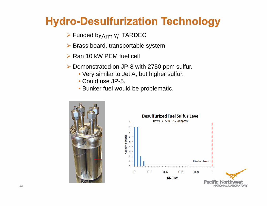
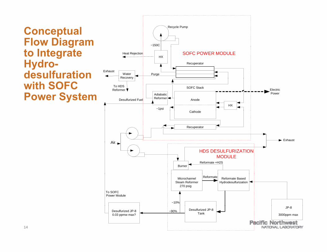
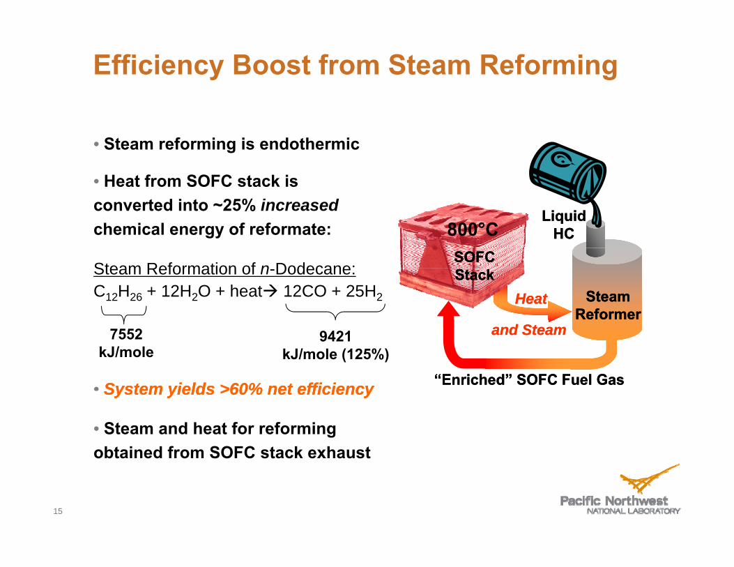
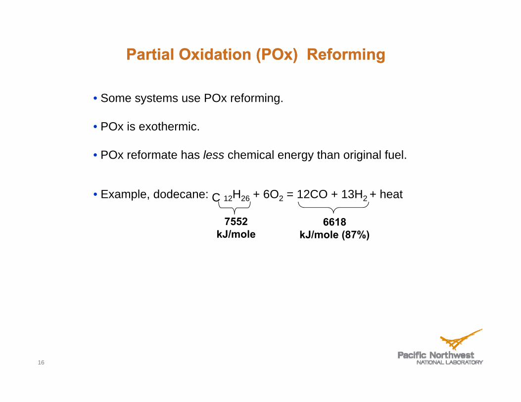
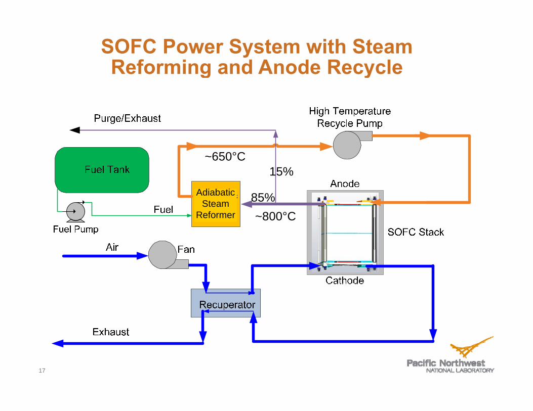
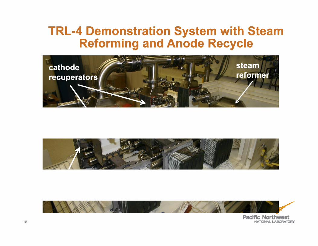
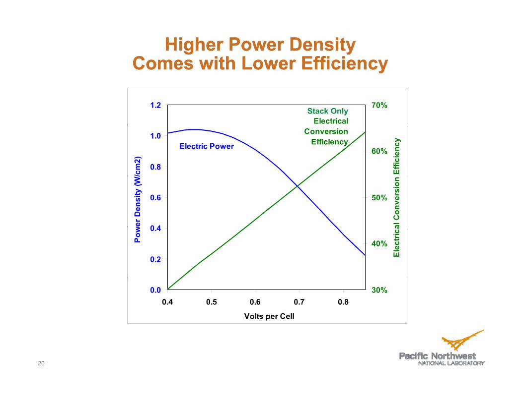
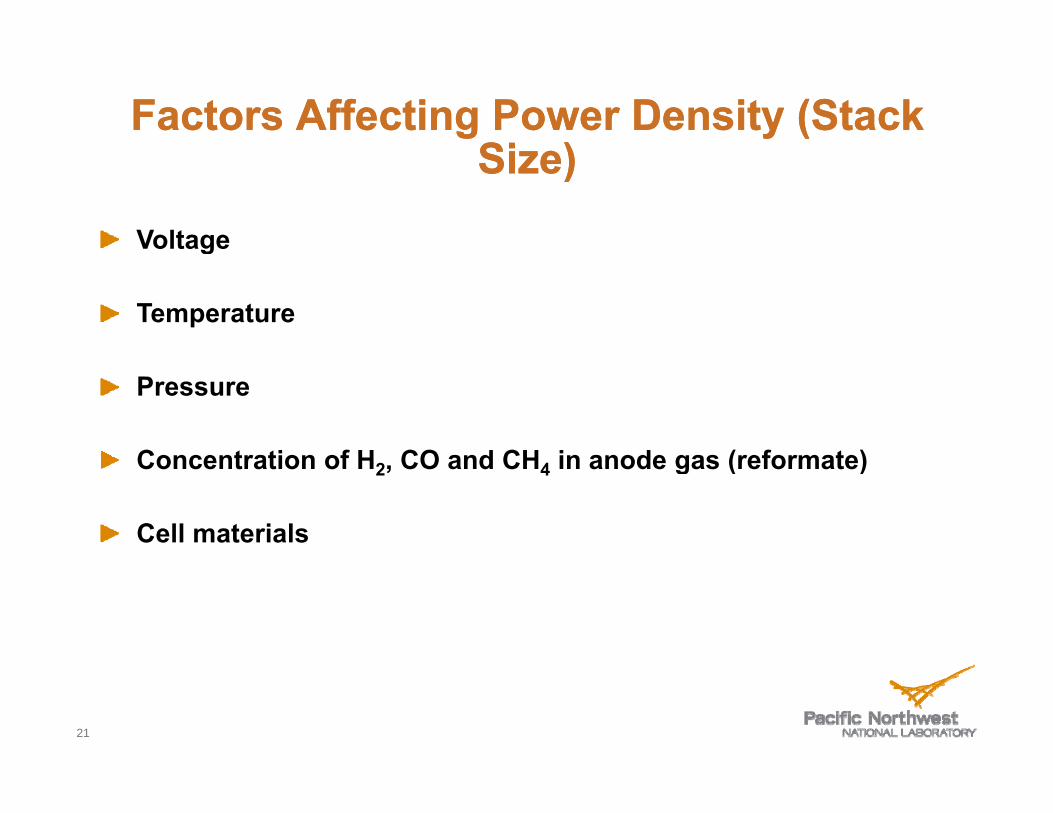
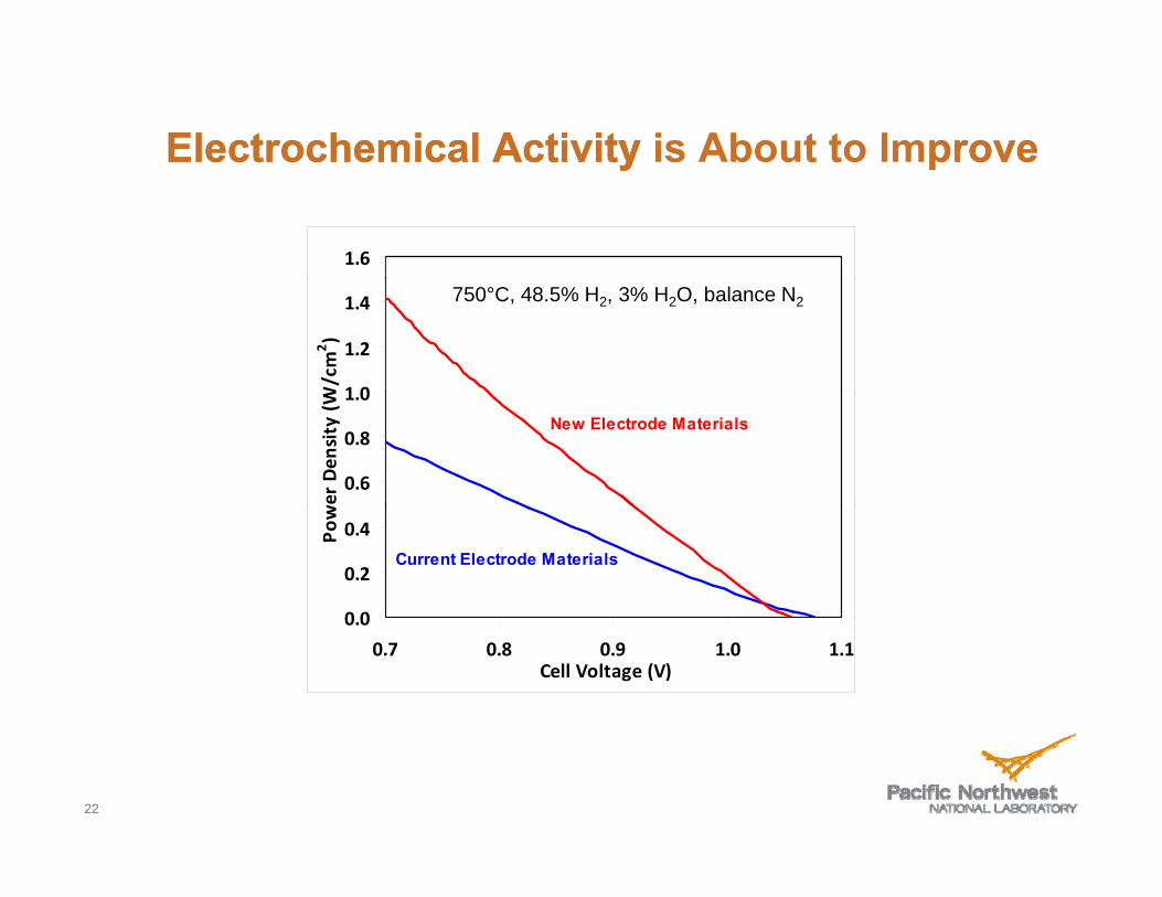
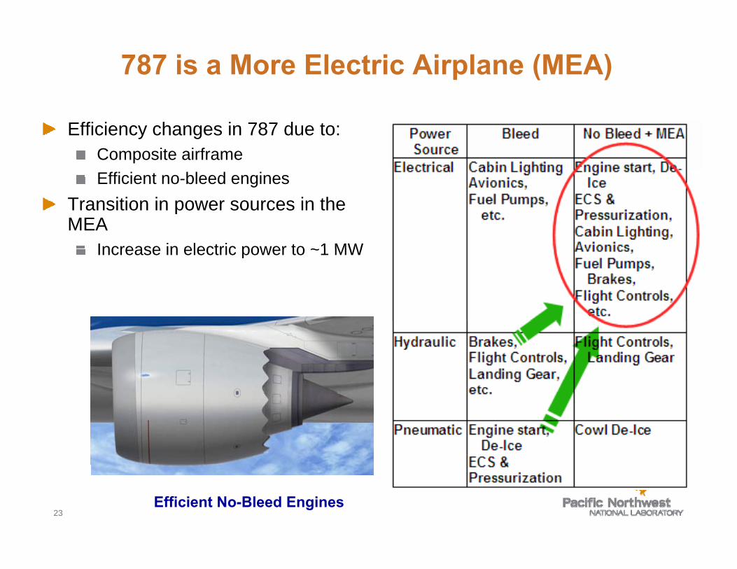
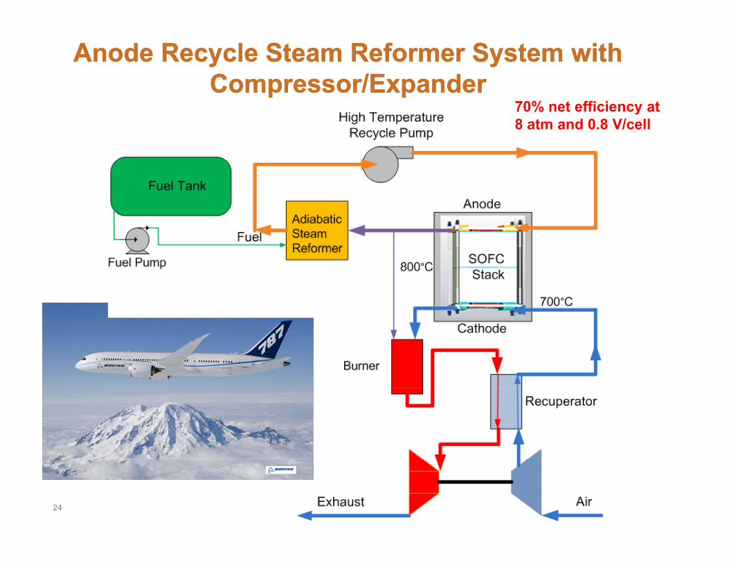
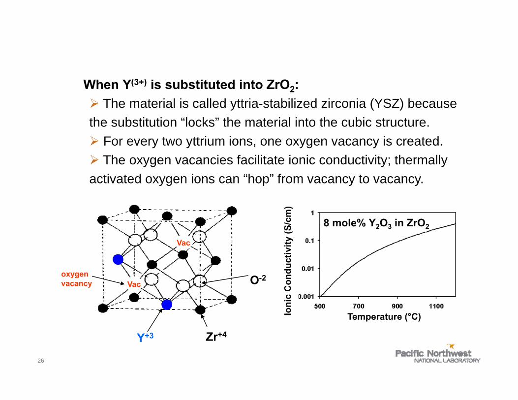
Solid Electrolyte
When Y(3+) is substituted into ZrO2 frac34 The material is called yttria-stabilized zirconia (YSZ) because the substitution ldquolocksrdquo the material into the cubic structure the substitution locks the material into the cubic structure frac34 For every two yttrium ions one oxygen vacancy is created frac34 The oxygen vacancies facilitate ionic conductivity thermally actitivatted oxygen iions can ldquohoprdquo f rdquo from vacancy tto vacancy d ldquoh
cm
)
8 mole Y2O3 in ZrO2
nduc
tivity
(S
8 mole Y2O3 in ZrO2
O 2
Vac
oxygen
Ioni
c C
on
Temperature (degC)
O-2 Vac
oxygen vacancy
26
Zr+4Y+3
frac34
=
Solid Electrolyte
frac34Every modern car contains a solid oxide cell in the form of a zirconia oxygen sensor frac34The output voltage is governed by the Nernst equation
RT PO2 (air )Voltage = lnlnVoltage 4F PO2 (exhaust )
frac34Current is near zero
27
SOFC Schematic
hydrogenhydrogenH2 andor COhydrogenhydrogeny g
oxygenions
y g
oxygenions
2y g
oxygenions
y g
waterions
waterions
H2O andor CO2waterions
water
electron flowelectron flowelectron flowelectron flow
l i l l
dl i l l
dl i l l
dl i l l
d
oxygen
electrical load
oxygen
electrical load
oxygen
electrical load
oxygen
electrical load
H2 andor COygygygyg
oxygen ions
2
ions H2O andor CO2
cathodecathodecathodecathode eeeelllleeeecccc anodetrolyte anodetrolytetrolytetrolyte anodeanode catalyzescatalyzes catalyzescatalyzes
frac12frac12 OOfrac12frac12 22OO + 2+ 222 ee++ --2e2e IcircIcirc OO== + H+ HOO 22IcircIcirc HH22O + 2O + 2ee-shyIcircIcirc OOOO == ++ HH22IcircIcirc HH22OO ++ 2e2e and Oand O== + C+ COOIcircIcirc COCO22 + 2e+ 2e-shy
28
Upper Limit for Steel Framed Planar SOFCUpper Limit for Steel Framed Planar SOFCTechnology ~850Technology ~850degdegCC
18 Fuel
1 2
14
16
820degC
H2 076 CO 014
H2O 005 CO2 001 CH4 003
(Mole Fraction)
08
10
12
r Den
sity
(Wc
m2 )
04
06Pow
er
735degC
650degC
00
02
04 05 06 07 08 09 10 11
Cell Voltage (V)
650degC
Cell Voltage (V)
29
Effect of Pressure on SOFC PowerEffect of Pressure on SOFC Power DD iittDDensensitityy
14
10
12 W
cm
2)
06
08
wer
Den
sity
(W
Model Results 750degC
0 0
02
04Pow 750degC
Steam RecycleReformate
00 0 1 2 3 4 5 6 7 8 9 10
System Pressure (Atm)
30
Reformate Gives Lower PowerReformate Gives Lower Power than Moist Hydrogenthan Moist Hydrogen
12 B th t 800degC hi h f l fl tBoth at 800degC high fuel flow rate
80 Recycle ReformateReformate 21 H2
31 H2O 16 CO 32 CO2
10 Common Test Fuel 49 H208 3 H2O
Balance N2
06
0 404
02
0 000
07 08 09 10 11 Cell Voltage (V)
Poweer
Den
sity
(Wcm
2 )
31
Delphi Generation 4Delphi Generation 4 SOFC TechnologySOFC Technology
Delphi Gen 4 Cassette 403 cm2 Active Area
Manifold load plate and 620 g current collectors = 335 kg
32
Predicted Effects of Pressure and Cell VoltagePredicted Effects of Pressure and Cell Voltage onon SystemSystem EfficiencyEfficiency andand SStacktack MassMassonon SystemSystem EfficiencyEfficiency andand StackStack MassMass
For SOFC System with Steam Reformer Anode Recycle and CompressorExpander
EfficiencyMass SOFC Cell Voltage
Pressure 085 080 075 070 08 atm 757455 713358 682168 641608 3 atm 754291 701933 661404 611120 8 atm 752959 701333 651034 61859
Efficiency = Net Electrical Energy Supplied to Bus LHV of KeroseneEfficiency = Net Electrical Energy Supplied to Bus LHV of Kerosene
Mass is for cassettes needed to generate 821 kW gross power
33
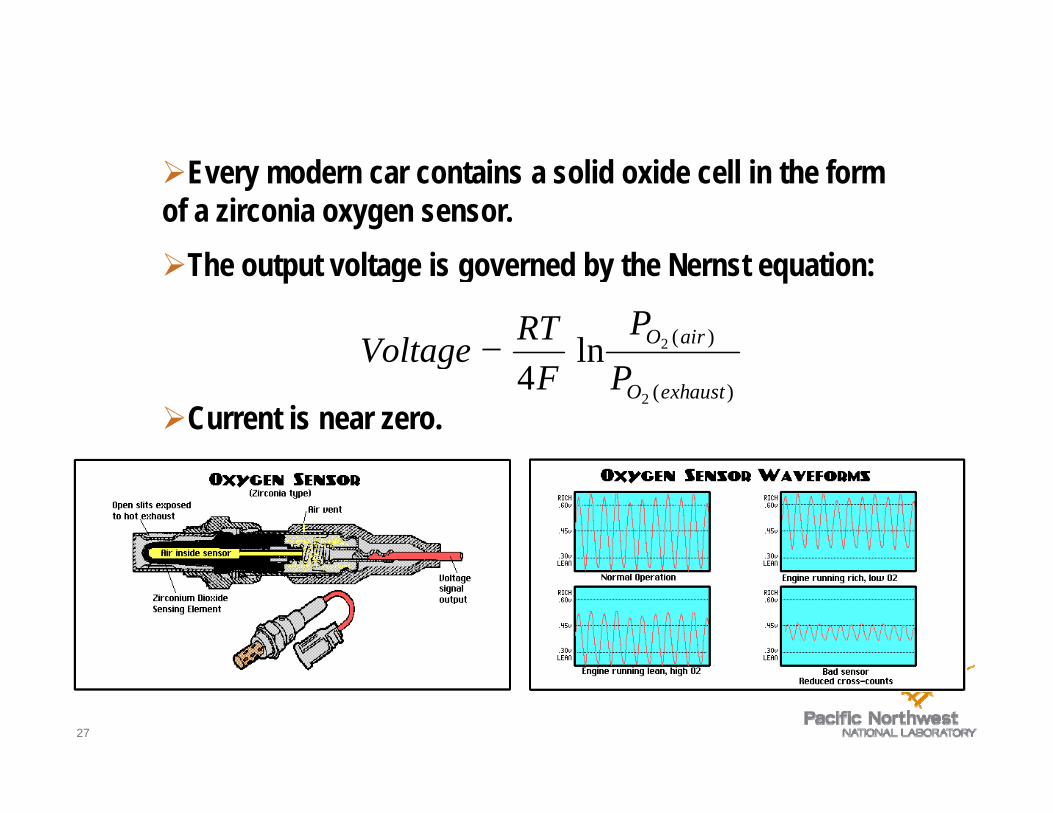
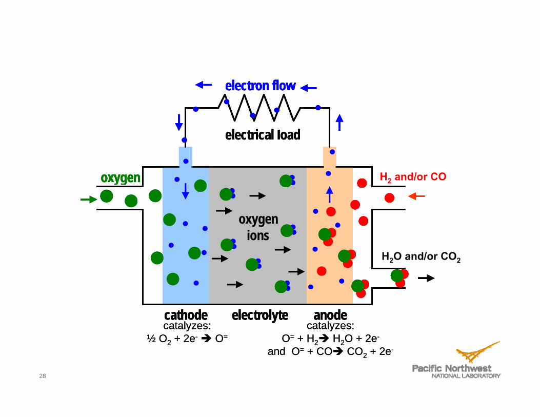
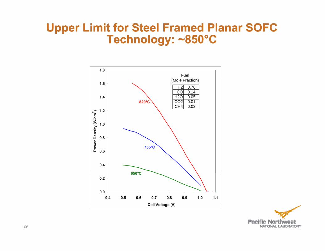
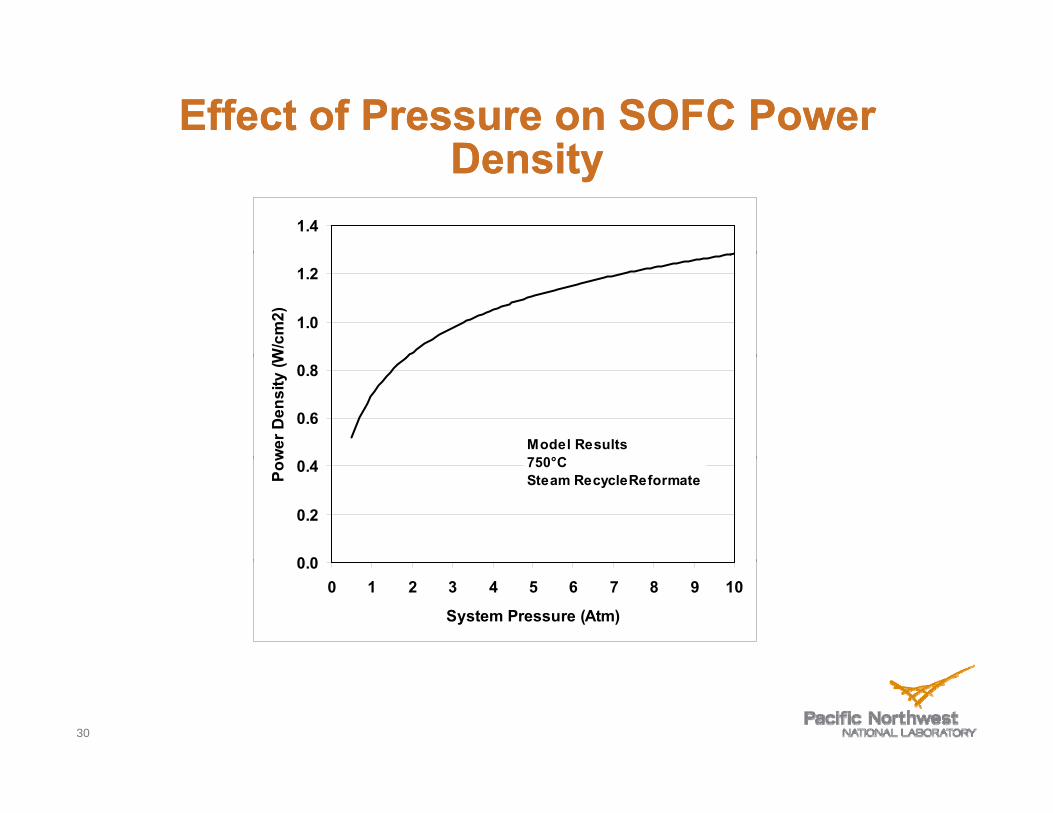
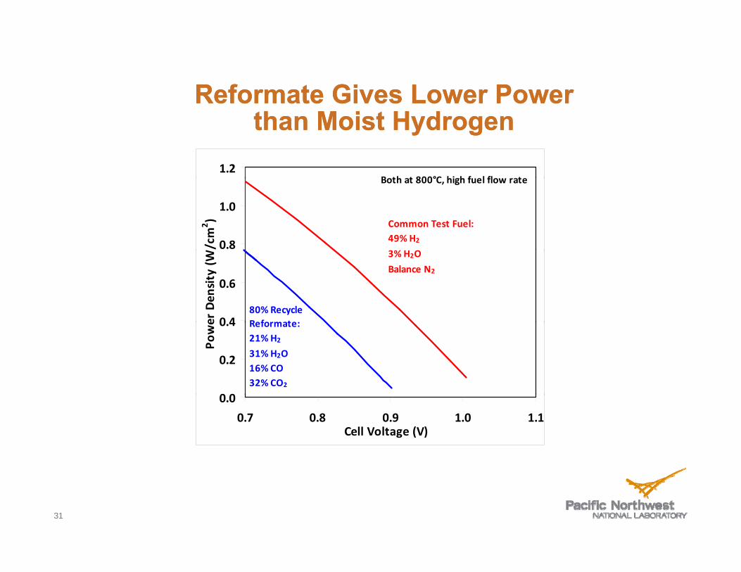
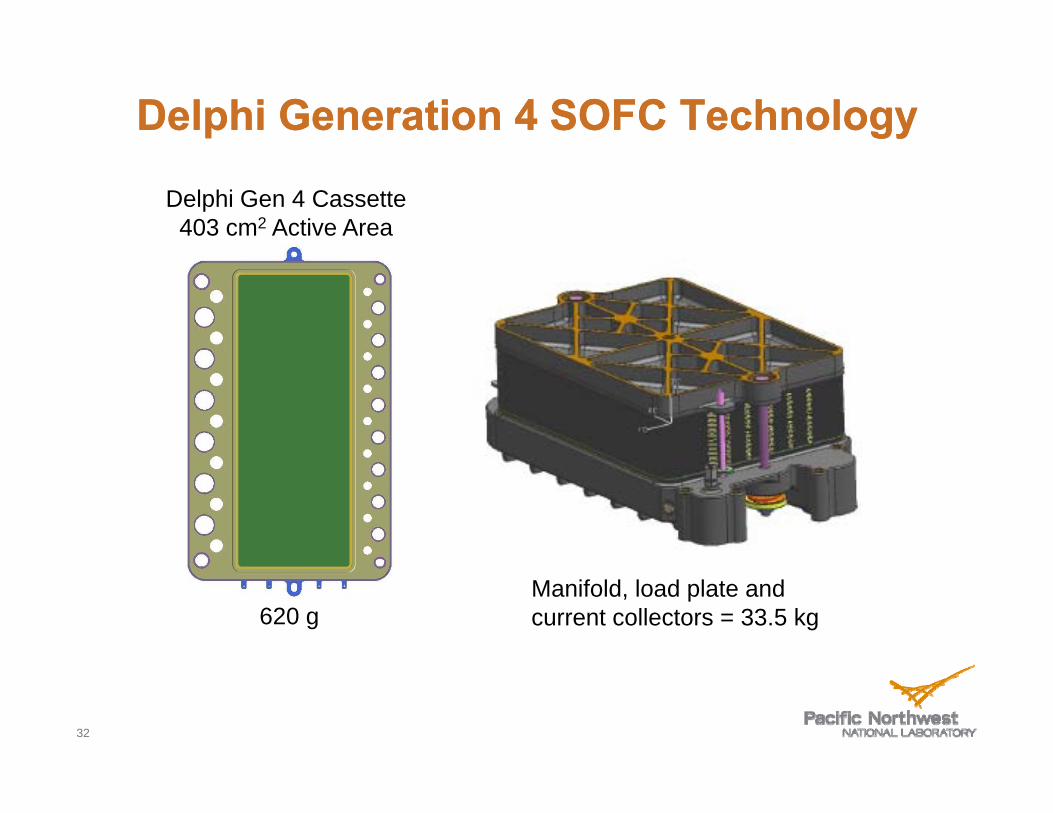
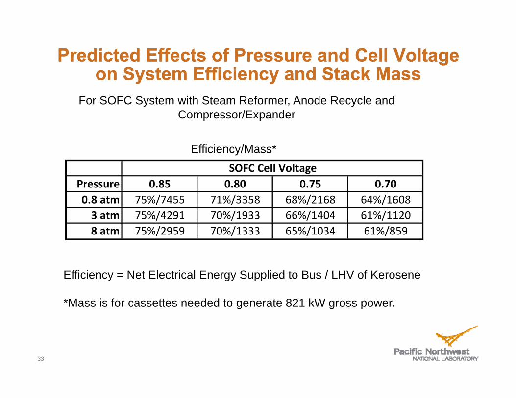