Embed Size (px)
Citation preview
1
Computer Aided Design
Solid models and B-REP
2
Computer Aided Design
Solid modelling
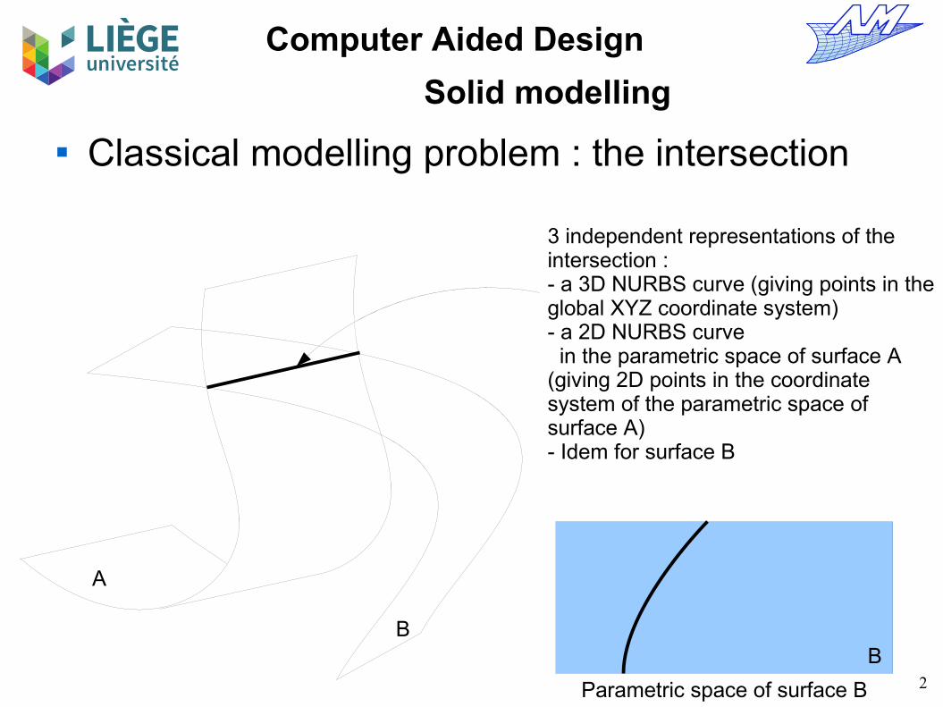
Classical modelling problem : the intersection
3 independent representations of the intersection :- a 3D NURBS curve (giving points in the global XYZ coordinate system)- a 2D NURBS curve in the parametric space of surface A(giving 2D points in the coordinate system of the parametric space of surface A)- Idem for surface B
A
BB
Parametric space of surface B

3
Computer Aided Design
Solid modelling
Theoretically, these three representations are equivalent ...
In practice, there are numerical approximations NURBS are finite approximation spaces; therefore
approximation/interpolation errors do occur. The use of floating point numbers with a finite binary
representation of the mantissa lead to numerical errors There is no robust way to ensure, in a geometrical
sense, that a curve located on surface A is the same as the corresponding curve on surface B, i.e. that both surfaces are neighbours, and share the same edge.
3 independent representations of the intersection :- a 3D NURBS curve- a 2D NURBS curve (parametric space of surface A)- a 2D NURBS curve (parametric space of surface B)
AB

4
Computer Aided Design
Solid modelling
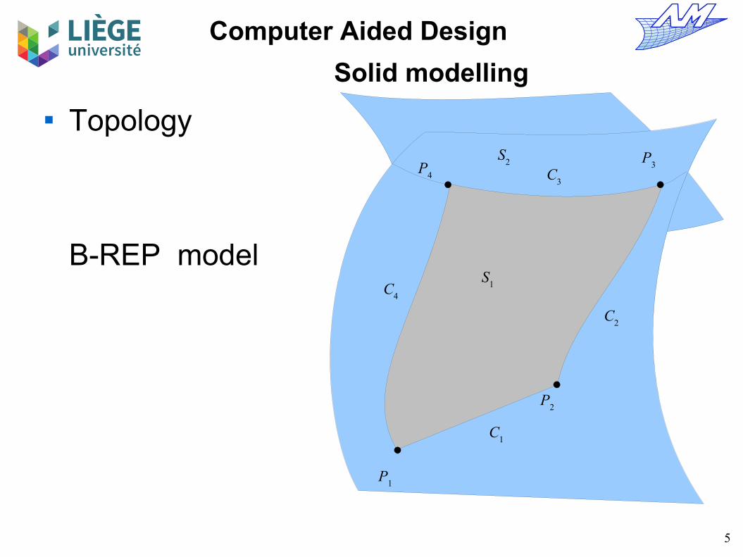
Definition of a topology : non geometric relations between entities.
This allows to unify the calculations (of points, normals, etc...) on entities shared (or bounding) other entities (eg. an edge shared by surfaces).
It also allows the explicit definition of volumes – from the surfaces that bound the volume.
It may also solve the problem of orientation of surfaces
5
Computer Aided Design
Solid modelling
Topology
B-REP model
P1
P2
P4
P3
C3
C1
C2
C4
S1
S2

6
Computer Aided Design
Solid modelling
B-Rep model « Boundary representation » Model based on the representation of surfaces Model of exchange (STEP format) and definition The “natural” set of operators is richer than for CSG
Extrusion, chamfer etc ... Does not carry the history of construction of the
model (whereas CSG usually does)
7
Computer Aided Design
Solid modelling
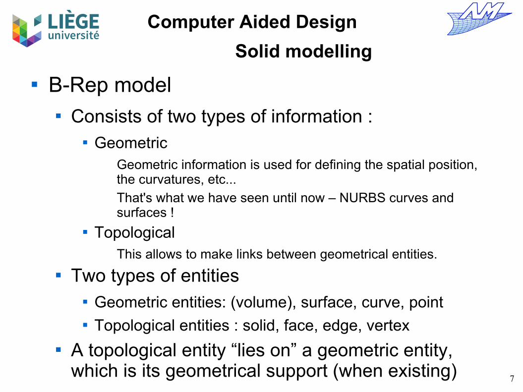
B-Rep model Consists of two types of information :
GeometricGeometric information is used for defining the spatial position, the curvatures, etc...
That's what we have seen until now – NURBS curves and surfaces !
TopologicalThis allows to make links between geometrical entities.
Two types of entities Geometric entities: (volume), surface, curve, point Topological entities : solid, face, edge, vertex
A topological entity “lies on” a geometric entity, which is its geometrical support (when existing)
8
Computer Aided Design
Solid modelling
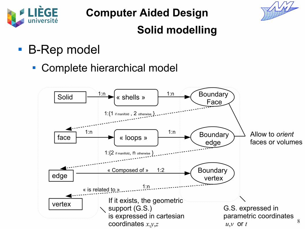
B-Rep model Complete hierarchical model
Solid « shells » Boundary Face
face « loops » Boundaryedge
edge Boundary
vertex
vertex G.S. expressed inparametric coordinates u,v or t
If it exists, the geometric support (G.S.) is expressed in cartesian coordinates x,y,z
« Composed of »
« is related to »
1:n 1:n
1:{1 if manifold , 2 otherwise }
1:n 1:n
1:{2 if manifold, n otherwise }
1:2
1:n
Allow to orient faces or volumes
9
Computer Aided Design
Solid modelling

10
Computer Aided Design
Solid modellingFace 1.the geometric support is surface 1,which is a surface of revolution around the axis (Oz).
Definition of the face 1 in the parametric space of the surface 1
Edge 1.the geometric support is the curve_xyz 2.In the parametric spaceof the surface 1, corresponds to two boundary edges : 1 et 11
Boundary edge 1.the geometric support is a straight line (curve_uv 1) in the parametric space of the surface 1
vertex 1.Coordinates x,y,z
Definition of the edge 1 in the parametric space of the curve 1
Boundary vertex 1Point_t t
1
Boundary edge 11.the geometric support is another straight line in the parametric space of the surface 1
vertex 2.Point xyz
loops
Boundary edge corresponding to a degenerated edge (zero length and identical points of departure and arrival: vertex 2)
Boundary vertex 2Point_t t
2

11
Computer Aided Design
Solid modelling
Solid 1: shell 1 G.S. : Nil
shell 1 : Boundary face 1 Boundary face 2 … Boundary face 76
Boundary face 1 : Face 1 G.S. : Nil
Loop 1 : Boundary edge 1 ... Boundary edge 12
Loop 2 : Boundary edge 13 Boundary edge 14 Boundary edge 15 Boundary edge 16
Face 1 : Loop 1 Loop 2 Loop 3 Loop 4 G.S. : Surface_xyz 1
Loop 3 (4) : Boundary edge 17 (21) ... Boundary edge 20 (24)
Boundary edge 1 Edge 1 G.S. : Curve_uv 1
Edge 1 Boundary vertex 1 Boundary vertex 2 G.S. : Curve_xyz 2
Boundary vertex 1 Vertex 1 G.S. : Point_t 1
Vertex 1 G.S. : Point_xyz 2
Excerpt of the B-REP topology of the propeller

12
Computer Aided Design
Solid modelling
Links between the B-REPtopology and the actualgeometry of the propeller
Face 1 : Loop 1 Loop 2 Loop 3 Loop 4 G.S. : Surface_xyz 1
Boundary edge 1 Edge 1 G.S. : Curve_uv 1
Edge 1 Boundary vertex 1 Boundary vertex 2 G.S. : Curve_xyz 2
Boundary vertex 1 vertex 1 G.S. : Point_t 1
Vertex 1 G.S. : Point_xyz 2
Surface_xyz 1 :Surface of revolutionNURBS Surfaceapplication (u,v) → (x,y,z)
Curve_uv 1 :Straight lineapplication (t) → (u,v)
Curve_xyz 2 :NURBS Curveapplication (t) → (x,y,z)
Point_t 1 t = t1
Point_xyz 2 x=x1, y=y1, z=z1
13
Computer Aided Design
Solid modelling
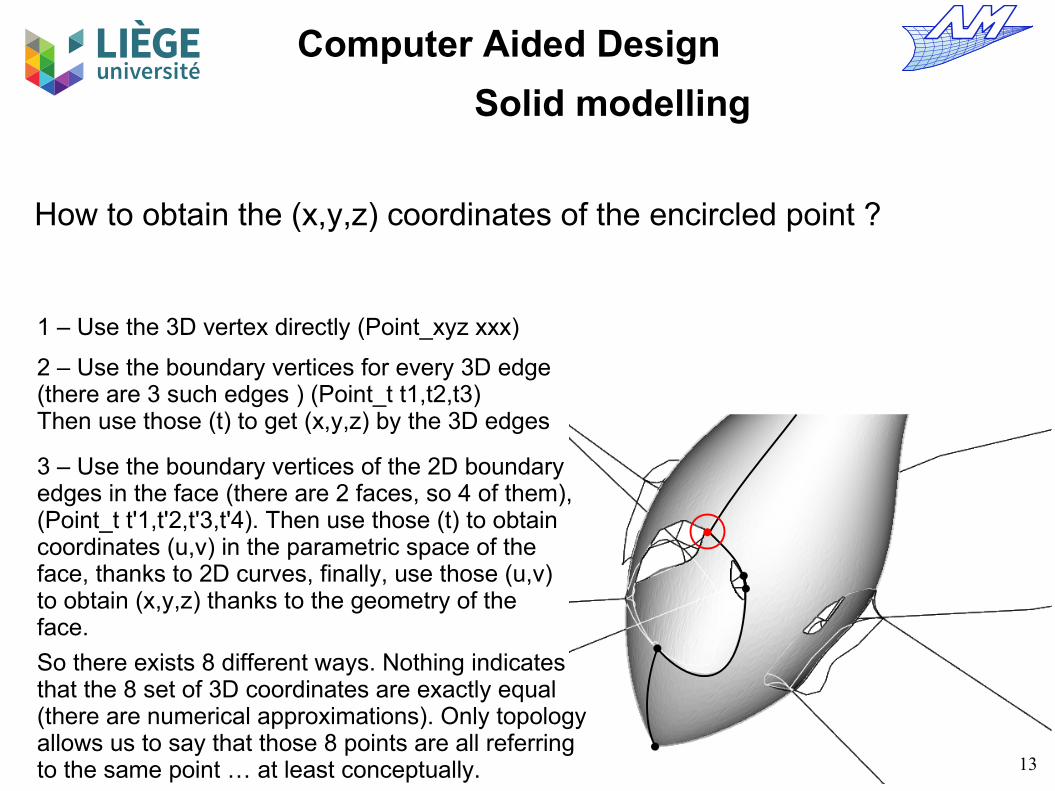
How to obtain the (x,y,z) coordinates of the encircled point ?
1 – Use the 3D vertex directly (Point_xyz xxx)
2 – Use the boundary vertices for every 3D edge (there are 3 such edges ) (Point_t t1,t2,t3)Then use those (t) to get (x,y,z) by the 3D edges
3 – Use the boundary vertices of the 2D boundary edges in the face (there are 2 faces, so 4 of them),(Point_t t'1,t'2,t'3,t'4). Then use those (t) to obtain coordinates (u,v) in the parametric space of the face, thanks to 2D curves, finally, use those (u,v) to obtain (x,y,z) thanks to the geometry of the face.
So there exists 8 different ways. Nothing indicates that the 8 set of 3D coordinates are exactly equal (there are numerical approximations). Only topology allows us to say that those 8 points are all referring to the same point … at least conceptually.
14
Computer Aided Design
Solid modelling
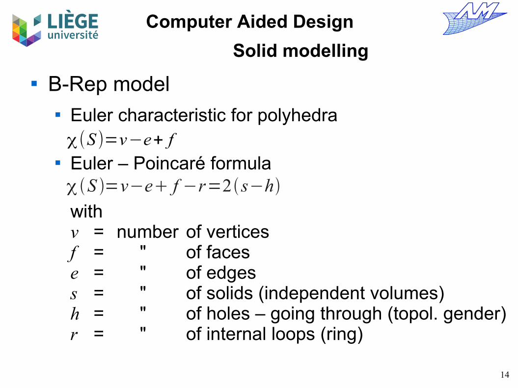
B-Rep model Euler characteristic for polyhedra
Euler – Poincaré formula
withv = number of verticesf = " of facese = " of edgess = " of solids (independent volumes)h = " of holes – going through (topol. gender)r = " of internal loops (ring)
χ(S )=v−e+ f
S =v−e f −r=2 s−h

Computer Aided Design
Euler's formula
Euler characteristic
Example : Cubev – e + f = k Opened and flattened Cube
v – e + f = k -1
Step 0 : we take a face off the polyhedron and flatten it to obtain a plane graph

Computer Aided Design
Euler's formula
v – e + f = k - 1 +1e , +1fv – e + f = k - 1
Step 1 : Repeat the following operation :For each non triangular face, add one edge linking non related vertices.Each tome, the number of edges and faces is increased by 1.This is repeated until no non triangular faces remain.
+5e , +5fv – e + f = k - 1
Computer Aided Design
Euler's formula
v – e + f = k - 1 –1e , –1fv – e + f = k - 1
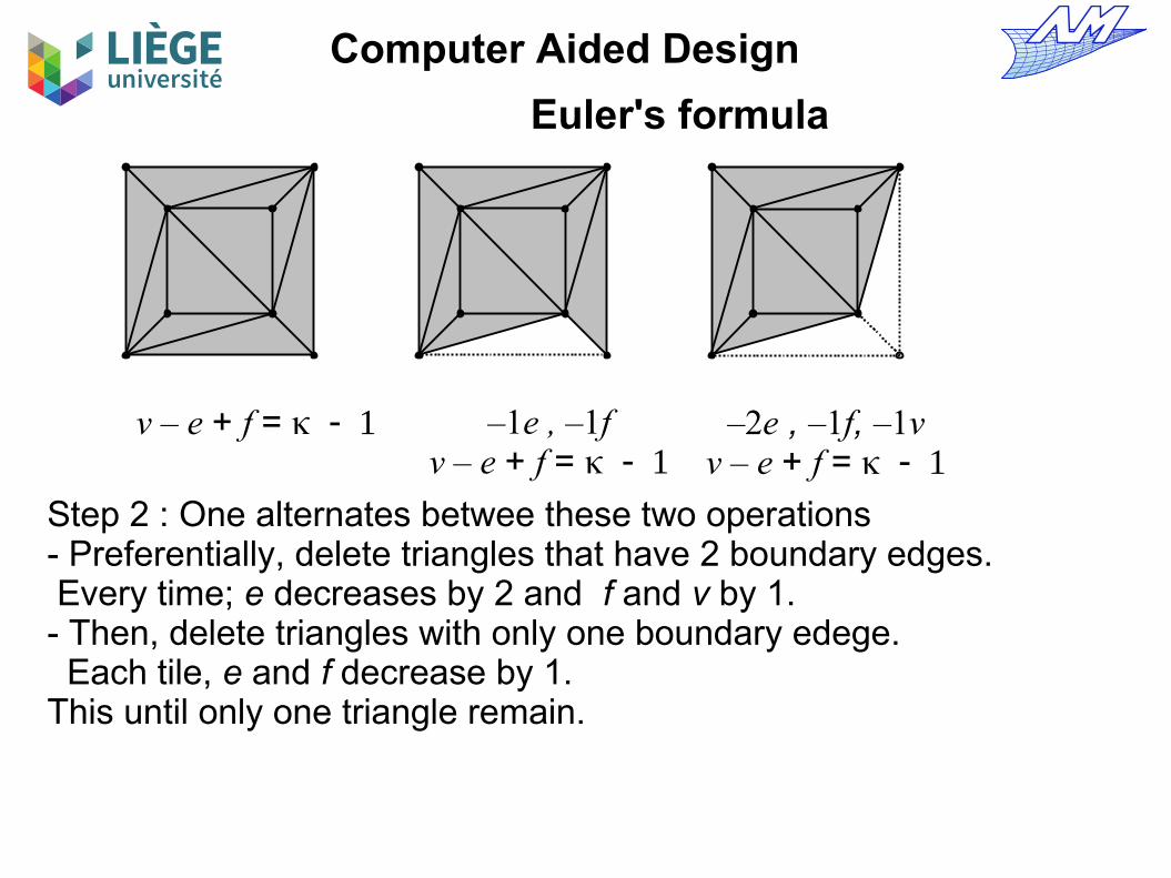
Step 2 : One alternates betwee these two operations- Preferentially, delete triangles that have 2 boundary edges. Every time; e decreases by 2 and f and v by 1.- Then, delete triangles with only one boundary edege. Each tile, e and f decrease by 1.This until only one triangle remain.
–2e , –1f, –1vv – e + f = k - 1

Computer Aided Design
Euler's formula
v – e + f = k - 1

Computer Aided Design
Euler's formula
Every polygon can be decomposed into trianglesTherefore, by applying the three operations described in the previous slides, we can transform the planar graph into a triangle without changing Euler's characteristic. The triangle satisfies obviously
with Therefore, the planar graph verifies the formula.
So the initial polyhedron satisfies :
v – e + f = k - 1
v – e + f = k = 2
k-1 = 1
20
Computer Aided Design
Solid modelling
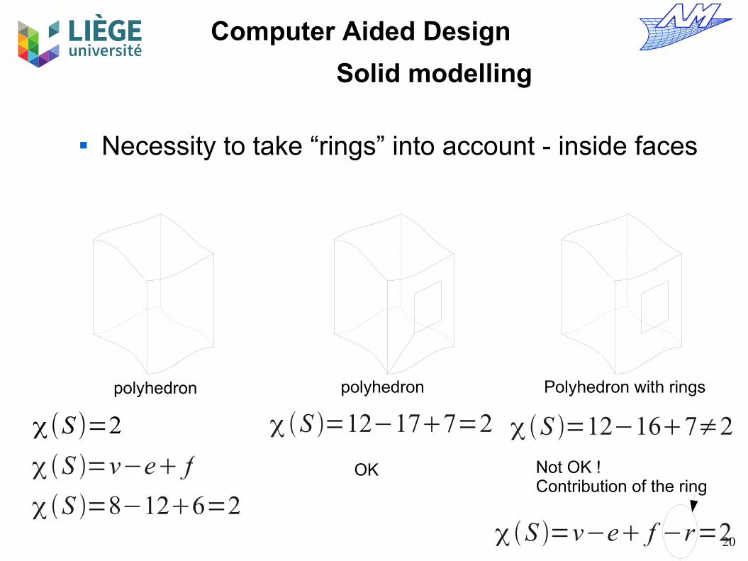
Necessity to take “rings” into account - inside faces
χ(S )=2
S =8−126=2
S =v−e f
S =12−177=2
OK
S =12−167≠2
Not OK !Contribution of the ring
polyhedron polyhedron Polyhedron with rings
S =v−e f −r=2

21
Computer Aided Design
Solid modelling
Necessity to take “holes” into account
χ(S )=2
S =8−126=2
S =v−e f OK
χ(S )=4−8+4≠2
Not OK !Contribution of the hole
polyhedron “Warped”polyhedron
Polyhedron with one hole, 4 edges less, 2 faces less, 4 vertices less
χ(S )=v−e+ f −r+2h=2
S =8−126=2
Not an edge !
22
Computer Aided Design
Solid modelling
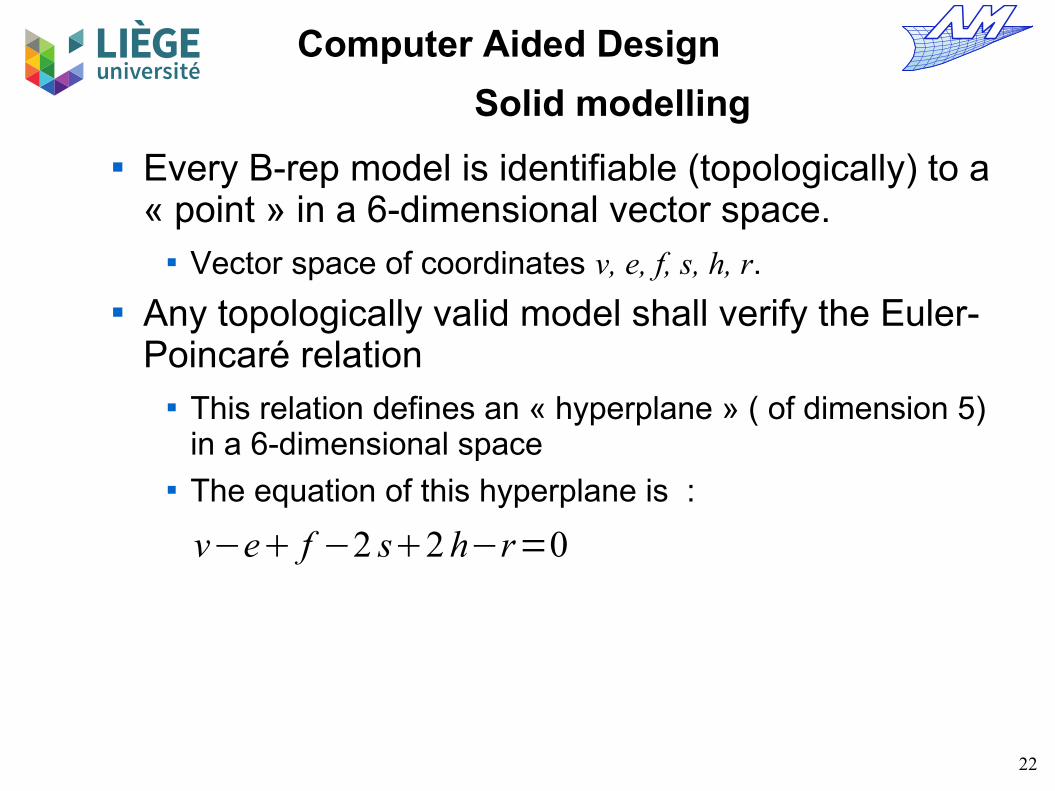
Every B-rep model is identifiable (topologically) to a « point » in a 6-dimensional vector space.
Vector space of coordinates v, e, f, s, h, r. Any topologically valid model shall verify the Euler-
Poincaré relation This relation defines an « hyperplane » ( of dimension 5)
in a 6-dimensional space The equation of this hyperplane is :
v−e f −2 s2 h−r=0

23
Computer Aided Design
Solid modelling
We can update a valid solid and modify the 6 numbers characterising a model with a transformation that yields a valid solid for which :
In this way, add a vertex ( ) must be accompanied, one way or another, by addition of an edge ( ) OR of the withdrawal of a face ( ), etc...
Elementary operations satisfying the Euler-Poincaré relation are called Euler operators.
They allow staying on the « hyperplane » of validity while changing the topological configuration
v−e f −2 s2 h−r=0
v v−e− e f f−2 s−2 s2 h2 h−r− r=0
⇒ v− e f −2 s2 h− r=0
v=1 e=1
f =−1

24
Computer Aided Design
Solid modelling
Euler operators The use of Euler operators guarantees the topological
validity of the result Here we don't check the geometric validity (self-
intersections etc...) We identify them under the form : MaKb where M =
Make K = Kill and a and b are a sequence of entities : vertex, edge, face, solid, hole or ring.
In total, there are 99 Euler operators aiming to modify the number of entities by at most one unit.
These are divided in 49 + 49 inverses, plus the identity operator.
Among those 49 operators , we can chose 5 linearly independent operators (the hyperplane has 5 dimensions)
Those 5 independent operators form a base for the hyperplane of topologically admissible models

25
Computer Aided Design
Solid modelling
Example of a set of Euler operators
Proof by Mäntylä (1984) that those operators allow to build every valid solid (since they are independent)
Those operators form a base of the space of valid configurations (the « hyperplane »)
inve
rses
MEV, Make an Edge and a VertexMEF, Make an Edge and a FaceMEKR, Make an Edge and Kill a RingMVFS, Make a Vextex, a Face and a ShellKFMRH, Kill a Face Make a Ring and a Hole
KEV, Kill an Edge and a VertexKEF, Kill an Edge and a FaceKEMR, Kill an Edge and Make a RingKVFS, Kill a Vertex, a Face and a ShellMFKRH, Make a Face, Kill a Ring and a Hole

26
Computer Aided Design
Solid modelling
There are three types of operators in this set : Skeleton operators MVFS and KVFS
Allow to build/destroy elementary volumes Local operators MEV, KEV, MEF, KEF, KEMR, MEKR
Allow to modify connectivities for existing volumes Don't modify fundamental topological characteristics of the
surfaces - nb of handles/ holes (topological gender) and number of independent volumes
Global operators KFMRH and MFKRH Allow to add / remove “handles” (change the topological gender)
Only the skeleton and global operators do change the topological gender.

27
Computer Aided Design
Solid modelling
Euler operators « Skeleton » operators
MVFS; KVFS Allow to « build » an « elementary » volume from void (which is
an admissible topological structure) – or destroy it.
Nihil
MVFS
KVFS
{v=0e=0f =0h=0r=0s=0
{v=1e=0f =1h=0r=0s=1
Only one face - its boundary is reduced to a single vertex

28
Computer Aided Design
Solid modelling
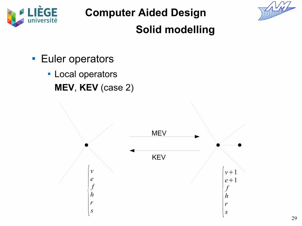
Euler operators Local operators
MEV, KEV (case 1)
MEV
KEV
{vefhrs
{v1e1fhrs
29
Computer Aided Design
Solid modelling
Euler operators Local operators
MEV, KEV (case 2)
MEV
KEV
{vefhrs
{v1e1fhrs

30
Computer Aided Design
Solid modelling
Euler operators Local operators
MEV, KEV (case 3)
MEV
KEV
{v=1e=0f =1h=0r=0s=1
{v=2e=1f =1h=0r=0s=1

31
Computer Aided Design
Solid modelling
Euler operators Local operators
MEF, KEF (case 1)
MEF
KEF
{vefhrs
{ve1f 1hrs
32
Computer Aided Design
Solid modelling
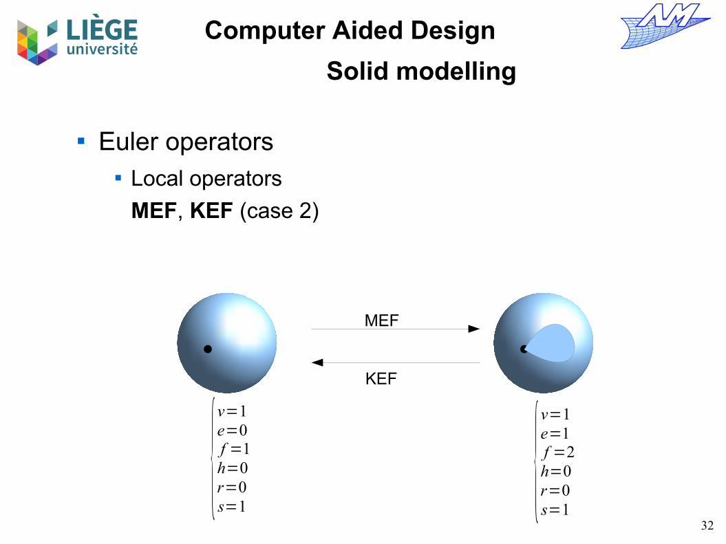
Euler operators Local operators
MEF, KEF (case 2)
MEF
KEF
{v=1e=0f =1h=0r=0s=1
{v=1e=1f =2h=0r=0s=1
33
Computer Aided Design
Solid modelling
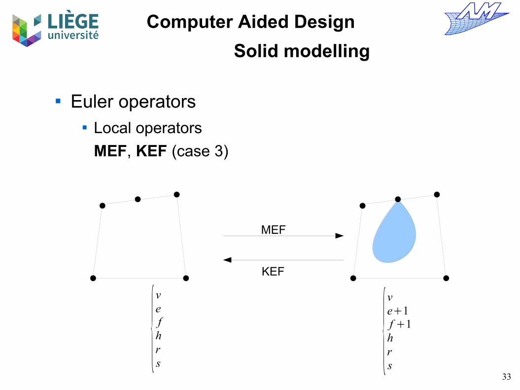
Euler operators Local operators
MEF, KEF (case 3)
MEF
KEF
{vefhrs
{ve1f 1hrs

34
Computer Aided Design
Solid modelling
Euler operators Local operators
KEMR, MEKR (case 1)
KEMR
MEKR
{vefhrs
{ve−1fhr1s
35
Computer Aided Design
Solid modelling
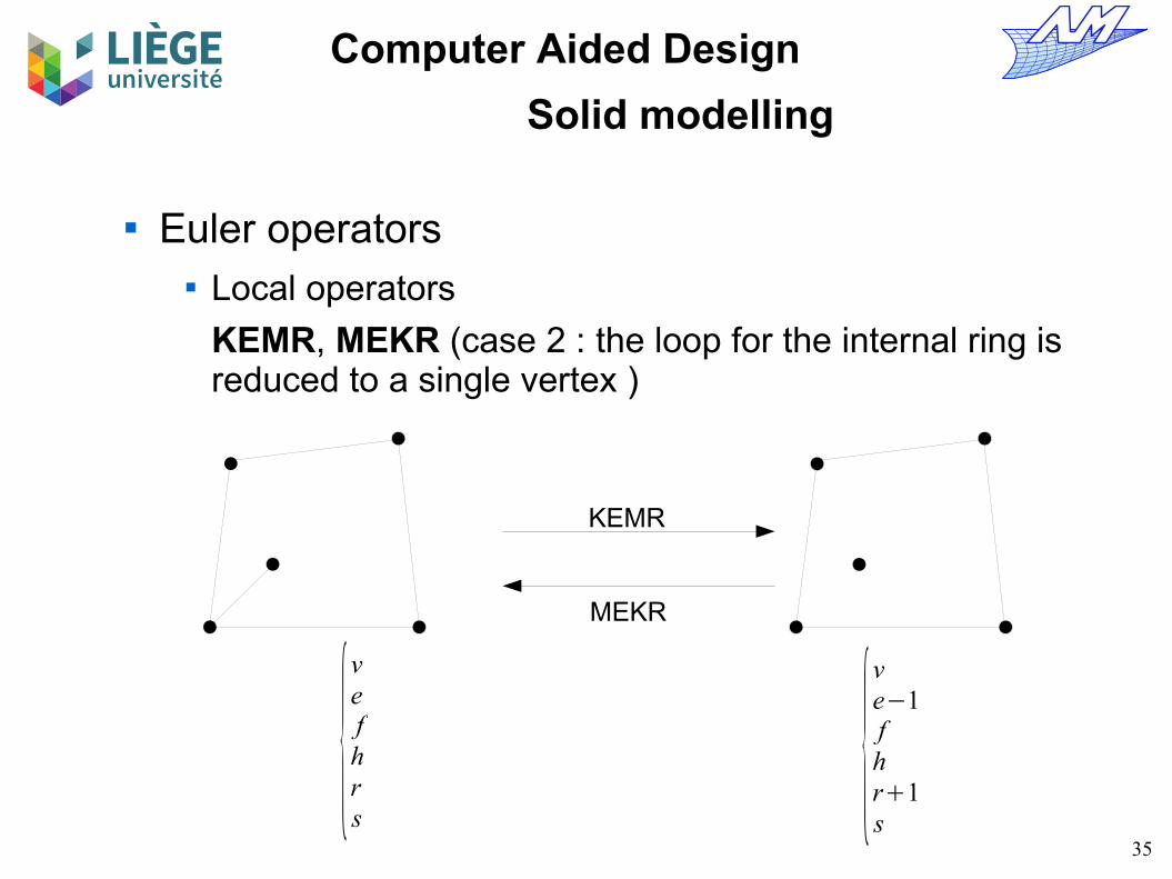
Euler operators Local operators
KEMR, MEKR (case 2 : the loop for the internal ring is reduced to a single vertex )
KEMR
MEKR
{vefhrs
{ve−1fhr1s
36
Computer Aided Design
Solid modelling
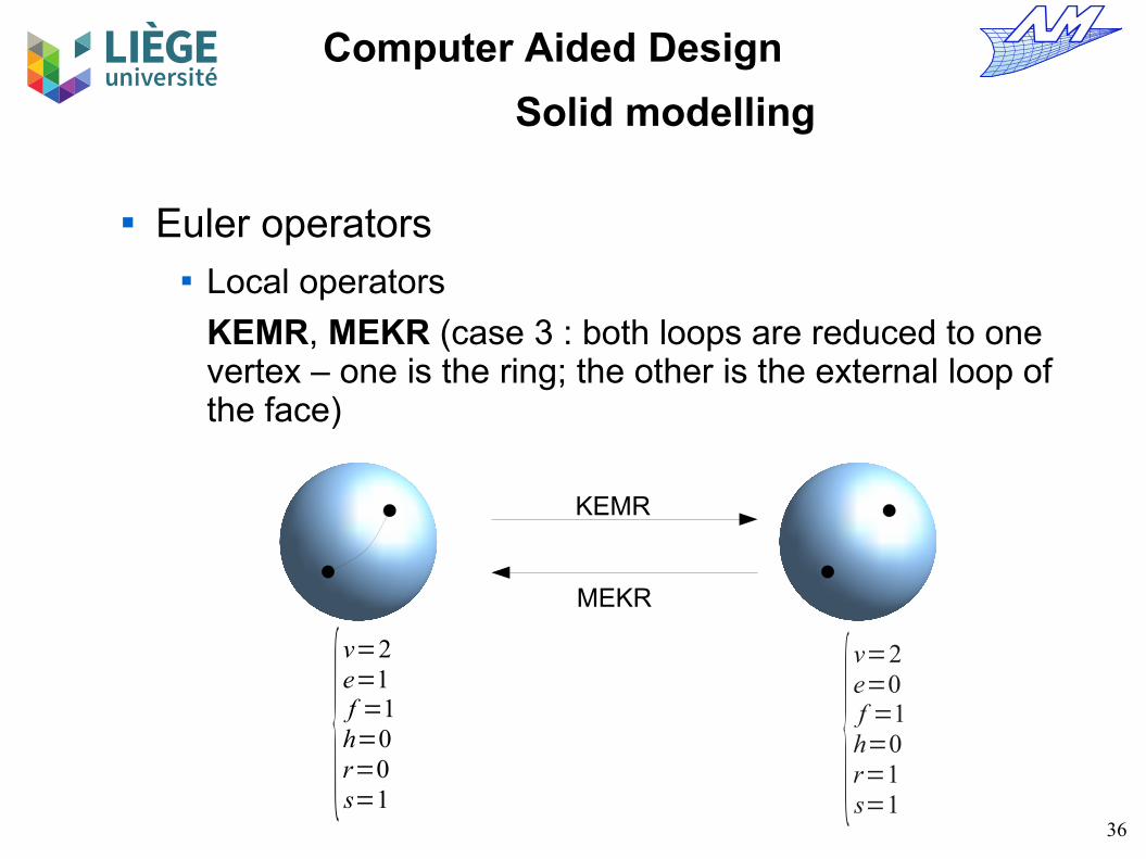
Euler operators Local operators
KEMR, MEKR (case 3 : both loops are reduced to one vertex – one is the ring; the other is the external loop of the face)
KEMR
MEKR
{v=2e=1f =1h=0r=0s=1
{v=2e=0f =1h=0r=1s=1

37
Computer Aided Design
Solid modelling
Euler operators Global operators
KFMRH, MFKRH (case 1 : allow the creation / destruction of holes in a solid)
KFMRH
MFKRH
{v=16e=24f =11h=0r=1s=1 {
v=16e=24f =10h=1r=2s=1

38
Computer Aided Design
Solid modelling
Euler operators Global operators
KFMRH, MFKRH (case 2) : join two independent solids : here more judiciously called Kill Face, Solid and Make Ring (KFSMR)
Interpretation of global operators is sometimes confusing
KFMRH (KFSMR)
MFKRH (MFSKR)
{v=16e=24f =12h=0r=0s=2 {
v=16e=24f =11h=0r=1s=1

39
Computer Aided Design
Solid modelling
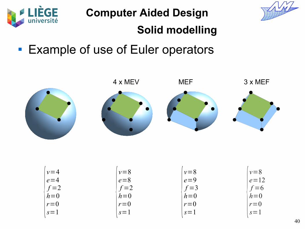
Example of use of Euler operators
MEVMVFS
{v=1e=0f =1h=0r=0s=1
2 x MEV
{v=4e=3f =1h=0r=0s=1
{v=4e=4f =2h=0r=0s=1
MEF
{v=2e=1f =1h=0r=0s=1
40
Computer Aided Design
Solid modelling
Example of use of Euler operators
{v=4e=4f =2h=0r=0s=1
{v=8e=8f =2h=0r=0s=1
4 x MEV
{v=8e=9f =3h=0r=0s=1
MEF
{v=8e=12f =6h=0r=0s=1
3 x MEF

41
Computer Aided Design
Solid modelling
Example of use of Euler operators
S. Havemann
42
Computer Aided Design
Solid modelling
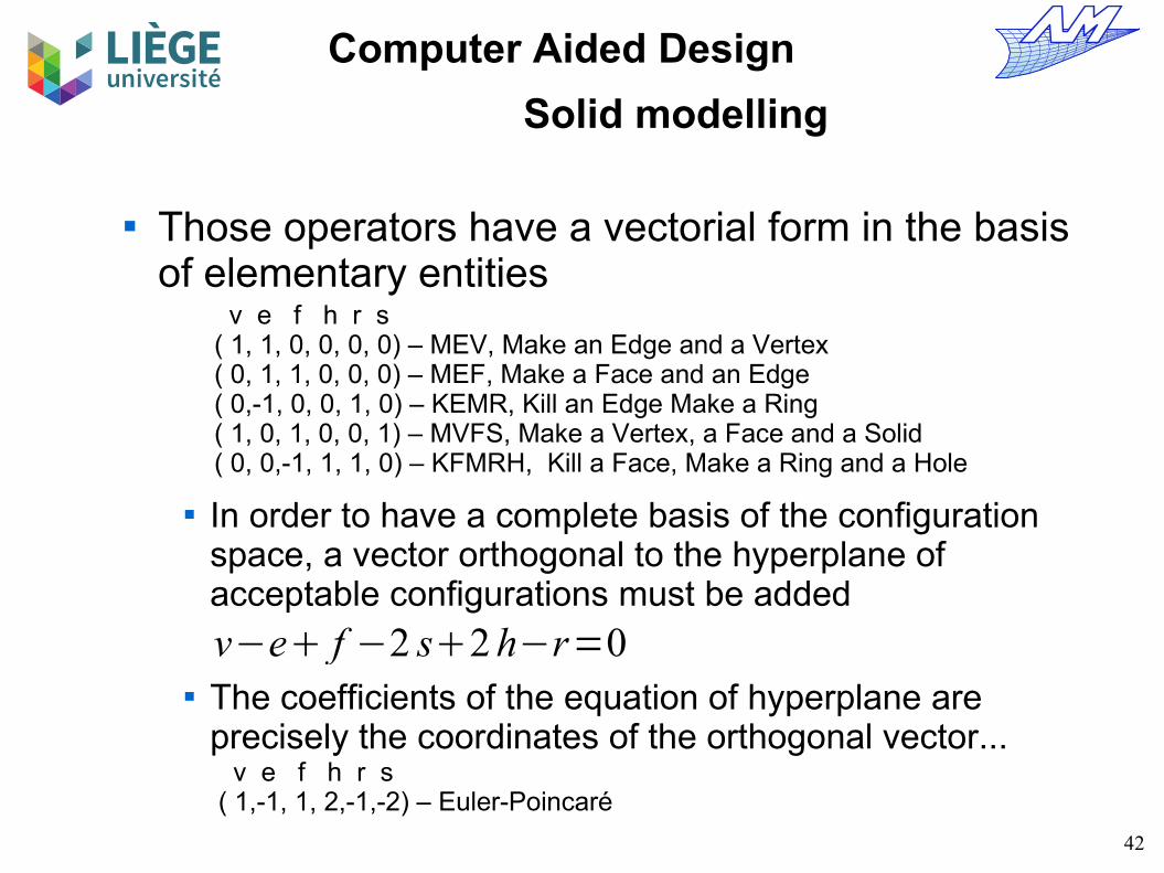
Those operators have a vectorial form in the basis of elementary entities
In order to have a complete basis of the configuration space, a vector orthogonal to the hyperplane of acceptable configurations must be added
The coefficients of the equation of hyperplane are precisely the coordinates of the orthogonal vector...
v e f h r s( 1, 1, 0, 0, 0, 0) – MEV, Make an Edge and a Vertex( 0, 1, 1, 0, 0, 0) – MEF, Make a Face and an Edge( 0,-1, 0, 0, 1, 0) – KEMR, Kill an Edge Make a Ring( 1, 0, 1, 0, 0, 1) – MVFS, Make a Vertex, a Face and a Solid( 0, 0,-1, 1, 1, 0) – KFMRH, Kill a Face, Make a Ring and a Hole
v−e f −2 s2 h−r=0
v e f h r s( 1,-1, 1, 2,-1,-2) – Euler-Poincaré

43
Computer Aided Design
Solid modelling
Any transformation can thus be expressed easily using matrix operations
A is a basis of the topological configurations space The columns of A are the variation of the number of
entities for each operator, and the E-P relation.
A=(1 0 0 1 0 11 1 −1 0 0 −10 1 0 1 −1 10 0 0 0 1 20 0 1 0 1 −10 0 0 1 0 −2
)Column corresponding to Euler-Poincaré's relation
Columns corresponding to each of the Euler operators
q=A⋅pVector representing the number of times that each operator is applied
Vector representing the number (or the variation of the number) of elementary entities
44
Computer Aided Design
Solid modelling
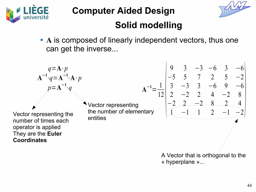
A is composed of linearly independent vectors, thus one can get the inverse...
Vector representing the number of times each operator is applied They are the Euler Coordinates
Vector representingthe number of elementary entities
A−1⋅q=A−1
⋅A⋅pp=A−1
⋅q A−1=
112 (
9 3 −3 −6 3 −6−5 5 7 2 5 −23 −3 3 −6 9 −62 −2 2 4 −2 8−2 2 −2 8 2 41 −1 1 2 −1 −2
)A Vector that is orthogonal to the « hyperplane »...
q=A⋅p
45
Computer Aided Design
Solid modelling
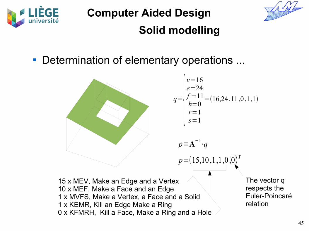
Determination of elementary operations ...
q={v=16e=24f =11h=0r=1s=1
=16,24 ,11 ,0 ,1,1
p=A−1⋅q
p=(15,10 ,1,1,0 ,0)T
15 x MEV, Make an Edge and a Vertex10 x MEF, Make a Face and an Edge1 x MVFS, Make a Vertex, a Face and a Solid1 x KEMR, Kill an Edge Make a Ring0 x KFMRH, Kill a Face, Make a Ring and a Hole
The vector q respects the Euler-Poincarérelation

46
Computer Aided Design
Solid modelling
Are Euler coordinates sufficient to define the topology of a solid ? → No.
7 x MEV, Make an Edge and a Vertex7 x MEF, Make an Edge and a Face1 x MVFS, Make a Vertex, a Face and a Solid0 x KEMR, Kill an Edge Make a Ring0 x KFMRH, Kill a Face, Make a Ring and a Hole
1 x MEF, Make an Edge and a Face1 x KEF, Kill an Edge and a Face
7 x MEV7 x MEF1 x MVFS0 x KEMR0 x KFMRH
Identical Euler coordinates
47
Computer Aided Design
Solid modelling
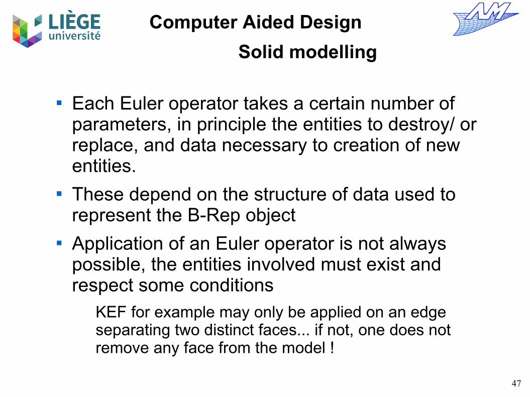
Each Euler operator takes a certain number of parameters, in principle the entities to destroy/ or replace, and data necessary to creation of new entities.
These depend on the structure of data used to represent the B-Rep object
Application of an Euler operator is not always possible, the entities involved must exist and respect some conditions
KEF for example may only be applied on an edge separating two distinct faces... if not, one does not remove any face from the model !
48
Computer Aided Design
Solid modelling
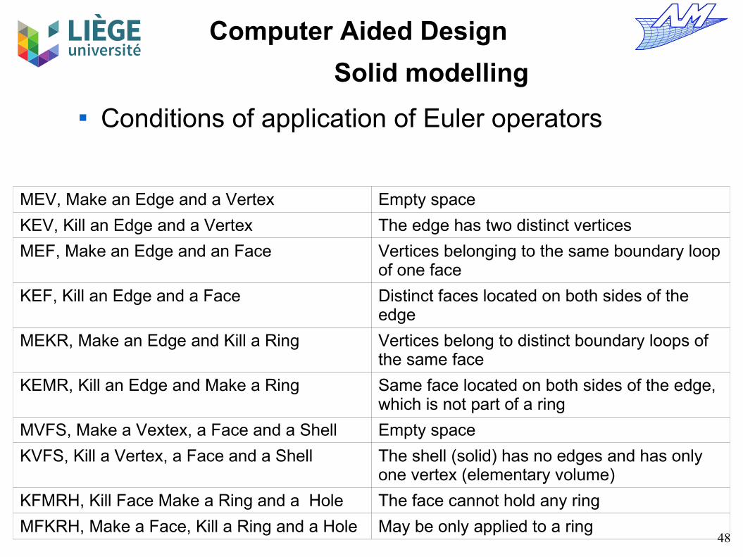
Conditions of application of Euler operators
MEV, Make an Edge and a Vertex Empty space
KEV, Kill an Edge and a Vertex The edge has two distinct vertices
MEF, Make an Edge and an Face Vertices belonging to the same boundary loop of one face
KEF, Kill an Edge and a Face Distinct faces located on both sides of the edge
MEKR, Make an Edge and Kill a Ring Vertices belong to distinct boundary loops of the same face
KEMR, Kill an Edge and Make a Ring Same face located on both sides of the edge, which is not part of a ring
MVFS, Make a Vextex, a Face and a Shell Empty space
KVFS, Kill a Vertex, a Face and a Shell The shell (solid) has no edges and has only one vertex (elementary volume)
KFMRH, Kill Face Make a Ring and a Hole The face cannot hold any ring
MFKRH, Make a Face, Kill a Ring and a Hole May be only applied to a ring

49
Computer Aided Design
Solid modelling
Some examples of the application of Euler operators (not shown here) Extrusion of a face Junction of two solids Cutting out a solid by a plane Boolean operations between solids

50
Computer Aided Design
Solid modelling
The most used data structure in a manifold B-Rep representation : Half-Edge data structure
Edge e
HalfEdge he1 HalfEdge he2
Face A Face Be e
he1 he2
51
Computer Aided Design
Solid modelling
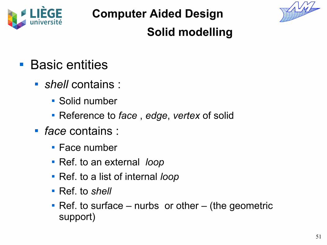
Basic entities shell contains :
Solid number Reference to face , edge, vertex of solid
face contains : Face number Ref. to an external loop Ref. to a list of internal loop Ref. to shell Ref. to surface – nurbs or other – (the geometric
support)

52
Computer Aided Design
Solid modelling
loop contains : Ref. to a list of halfedge Ref. to face
edge contains : Ref. to halfedge of straight line Ref. To the left halfedge Ref. to a curve – nurbs or other – (the geometric support)
halfedge contains : Ref. to the parent edge Ref. to the starting vertex Ref. to the holding loop
53
Computer Aided Design
Solid modelling
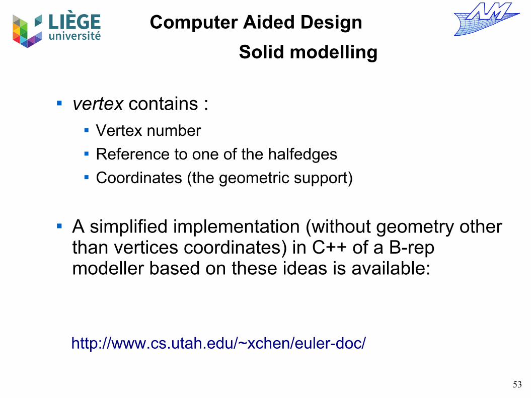
vertex contains : Vertex number Reference to one of the halfedges Coordinates (the geometric support)
A simplified implementation (without geometry other than vertices coordinates) in C++ of a B-rep modeller based on these ideas is available:
http://www.cs.utah.edu/~xchen/euler-doc/

54
Computer Aided Design
Solid modelling
B-Rep model Possibility of automatic topological operations
Here, elimination of small features in order to generate a mesh for numerical simulation in mechanical engineering.
V François

55
Computer Aided Design
Solid modelling
Bibliographic note
M. Mäntylä, An Introduction to Solid Modelling, Computer Science Press, 1988
I. Stroud, Solid Modelling and CAD Systems : How to Survive a CAD System, Springer, 2011(available on-line from the university campus)


![[8] Principles and Models of Solid Fuel Combustion](https://img.pdfslide.us/doc/110x75/544feca9af7959ff088b484f/8-principles-and-models-of-solid-fuel-combustion.jpg)

