Embed Size (px)
Citation preview
ADJUSTMENT PROCEDURE UC4, UC4MB44
1728 ORBIT WAY - MINDEN - NEVADA - 89423-4114 - PHONE: 775-782-1700 - FAX: 775-782-1701 - WEB: maxtonvalve.com - EMAIL: [email protected]
THE INFORMATION PRESENTED HEREIN IS FOR USE BY SKILLED HYDRAULIC ELEVATOR PROFESSIONALS
SPECIAL CONSIDERATIONS: Make all adjustments at minimum pressure (no load on elevator) except where noted. “IN” is ALWAYS (CW) clockwise. “OUT” is ALWAYS (CCW) counterclockwise. THE CONTROL PLATE ADJUSTERS HAVE SEAL NUTS, NOT LOCK NUTS. Adjust nut only to set seal friction (friction will maintain adjustment). When adjustment procedure calls for coils to be disconnected, disconnect them electrically. Do not remove them physically. Make adjustments with a minimum oil temperature of 80˚ F, not to exceed 100˚ F maximum. Maxton recommends the use of a 5 micron filtration system. With the presence of at least some adverse conditions in most installations, serious consideration should be given to overhaul or replacement of a control valve on a five year cycle.
GAUGE PORTS: Gauge ports 1/8 pipe sizes are provided at points A, B and S. A Port: Pump pressure (RELIEF, WORKING PRESSURE). B Port: Jack pressure (STATIC, DOWN RUNNING). S Port: Low pressure switch port. Note: The minimum operating pressure at port B should be at least 50 psi (3.4 bar) as car is moving down full speed with no load. See flow chart.
OPERATIONAL DATA: Min. / Max. Pressure: Max. Rated Flow: Operating Temperature: Optimal Temp. Range. Oil Type:
50-800 psi (3.4-55 bar) 185 gpm (700 l / min.) 80˚-150˚ F (26˚- 65˚ C) 100˚-130˚ F (38˚- 54˚ C) Hyd. ISO VG 32 150 SUS @ 100˚ F (38˚ C)
* SAFETACH performance meter validates valve adjustment by providing direct speed and acceleration (g-force) readouts.
Note: Consult factory when applications exceed pressure ratio over 2.5 to 1, example (Max. / Min. :280 / 100)
UP SECTION ADJUSTMENTS (Start with car at lower landing) DOWN SECTION ADJUSTMENTS (Start with car at upper landing) 1 BPS 2 UA 3 UL
4 UT 5 US
6
LS*
Disconnect the US coil, turn UA IN (CW) register an up call and turn BPS IN (CW) until the car just moves. Next, turn the BPS adjuster OUT (CCW) until it stops the movement of the car, then OUT 1/ 2 turn more. Snug lock nut on BPS adjuster and stop pump. NOTE: If car does not move with BPS fully IN (CW), the valve may be oversized for the job (consult factory for proper valve sizing). Reconnect the US coil. Register an up call (pump running, U & US coils energized, car should not move), slowly turn UA OUT (CCW) to attain full up speed within 24 to 36 inches. * (Accel 0.04g-0.09g). Disconnect the U coil. Turn UL adjuster IN (CW) to stop and register an up call. Leveling speed should be 3 to 5 fpm. (If not, readjust LS*). Turn UL adjuster OUT (CCW) to attain 9 to 12 fpm leveling speed. Reconnect the U coil and lower the car to
lowest landing. *(Read leveling speed). Register an up call and turn UT IN (CW) so that the car slows to provide 4 to 6 inches of stabilized up leveling. Repeat steps 3 and 4 as necessary. *(Decel 0.04g-0.09g). With US adjuster fully OUT (CCW), car should stop 1/4" to 3/8" below floor. After a normal up run, turn US IN (CW) as needed
to bring car to floor level. *(Stop 0.04g-0.09g). The pump must be timed to run ½ second after the car has reached the floor.
With empty car at bottom floor, disconnect U & US coils and register a call. The car must not move. If movement occurs, check BPS and US.
Dot on the LS adjuster should be referenced to the line between F / S. When necessary, disconnect the U coil and turn the UL adjuster IN (CW) to stop. Move the LS adjuster slightly toward S for slower or F for faster leveling speed. Set coarse adjustment from 3 to 5 fpm with the LS adjuster, then repeat step 3. * (Level Speed Test 3 to 5 fpm).
7 D 8 DA 9 DT 10 DL 11 DS
ML
R
Register a down call to set proper down speed with down speed adjuster D as required. Tighten the lock nut (snug) & send car to
upper landing. *(Read high speed). Start by turning DA and DL adjusters IN (CW) to stop. Register a down call and, turn the DA adjuster slowly OUT (CCW) until the car accelerates smoothly. Send car to upper landing.
*(Accel 0.04g-0.09g).
Register a down call and turn DT IN (CW) so that the car slows to provide 4 to 6 inches of stabilized down leveling.
* (Decel 0.04g-0.09g). Disconnect D coil. Register a down call and set down leveling speed at 6 to 9 fpm with the DL adjuster. Tighten the lock nut
(snug). Reconnect D coil. * (leveling speed 6 to 9 fpm).
Turn DS IN (CW), when necessary, for a softer stop. * (Stop 0.04g-0.09g).
MANUAL LOWERING: Turn ML screw OUT (CCW) to lower car downward at leveling speed when necessary.
RELIEF: a. Land car in pit and install pressure gauge in A port. b. Register an up call with a fully loaded car, making note of
Maximum operating pressure. c. Turn UA and RELIEF adjuster OUT (CCW) to stop. d. Close the manual shut off valve to the jack. e. Register an up call, observe pressure gauge and turn
RELIEF IN (CW) to increase pressure. Final setting should be in accordance with local code requirement not to exceed 150% of maximum operating pressure.
f. Tighten the lock nut (snug). g. Restart to check the pressure relief setting. Seal as
required. h. Open the manual shut off valve to the jack i. Readjust UA for proper Up Acceleration.*(Accel 0.04g-0.09g).
DEFAULT SETTINGS If valve is received from Maxton, only minor adjustments may be required.
DEFAULT SETTINGS If valve is received from Maxton, only minor adjustments may be required.
CONTROL PLATE CONTROL PLATE US
UP STOP
OUT
(CCW)
to stop. (faster rate) DT DOWN TRANSITION
OUT
(CCW) to stop. (faster rate)
UL UP LEVEL
IN
(CW)
to stop. (slower speed) DA DOWN ACCELERATION
OUT
(CCW) to stop. (faster rate)
UA UP ACCELERATION
IN
(CW)
to stop. (slower rate) DS DOWN STOP
OUT
(CCW) to stop. (faster rate)
UT UP TRANSITION
OUT
(CCW)
to stop. (faster rate) ML MANUAL LOWERING
IN
(CW) to stop.
VALVE BODY VALVE BODY BPS
BY-PASS SIZING
OUT
(CCW)
to stop. (delays up start) D DOWN SPEED OUT (CCW)
5 threads above lock nut. (faster speed)
LS*
LEVEL SPEED (factory set) DOT ON LINE (set 3-5 fpm) DL DOWN LEVEL OUT (CCW)
2 threads above lock nut. (faster speed)
R RELIEF (factory set)
APPROX 450 psi (CW increases pressure)
39\\SERVER\Catalog\CATALOG 2013\2013 Catalog REV 1.PDF
ADJUSTMENT PROCEDURE UC4, UC4MB44
1728 ORBIT WAY - MINDEN - NEVADA - 89423-4114 - PHONE: 775-782-1700 - FAX: 775-782-1701 - WEB: maxtonvalve.com - EMAIL: [email protected]
DL
D
B
A BPS
R
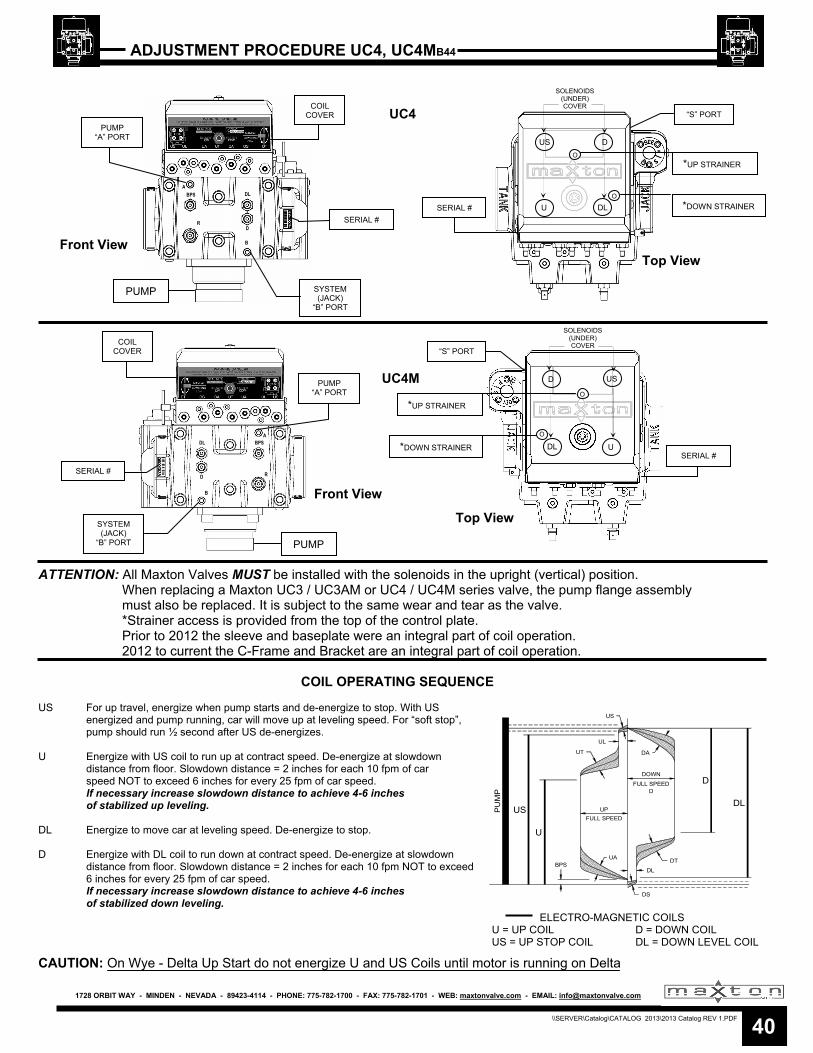
ATTENTION: All Maxton Valves MUST be installed with the solenoids in the upright (vertical) position. When replacing a Maxton UC3 / UC3AM or UC4 / UC4M series valve, the pump flange assembly must also be replaced. It is subject to the same wear and tear as the valve. *Strainer access is provided from the top of the control plate. Prior to 2012 the sleeve and baseplate were an integral part of coil operation. 2012 to current the C-Frame and Bracket are an integral part of coil operation.
COIL OPERATING SEQUENCE
US For up travel, energize when pump starts and de-energize to stop. With US
energized and pump running, car will move up at leveling speed. For “soft stop”, pump should run ½ second after US de-energizes.
U Energize with US coil to run up at contract speed. De-energize at slowdown distance from floor. Slowdown distance = 2 inches for each 10 fpm of car speed NOT to exceed 6 inches for every 25 fpm of car speed. If necessary increase slowdown distance to achieve 4-6 inches of stabilized up leveling. DL Energize to move car at leveling speed. De-energize to stop. D Energize with DL coil to run down at contract speed. De-energize at slowdown distance from floor. Slowdown distance = 2 inches for each 10 fpm NOT to exceed
6 inches for every 25 fpm of car speed. If necessary increase slowdown distance to achieve 4-6 inches
of stabilized down leveling.
CAUTION: On Wye - Delta Up Start do not energize U and US Coils until motor is running on Delta
A BPS
R
DL
D
B
UC4
UC4M
PUMP “A” PORT
COIL COVER
SYSTEM (JACK)
“B” PORT
PUMP “A” PORT
COIL COVER
SYSTEM (JACK)
“B” PORT
“S” PORT
SERIAL #
SOLENOIDS (UNDER) COVER
US D
U DL
SERIAL #
“S” PORT
US D
DL U
US
U
D
DL
UT
UL
US
UP
FULL SPEED
UABPS
DL
DT
DA
DOWN
FULL SPEEDD
DS
PU
MP
ELECTRO-MAGNETIC COILS U = UP COIL D = DOWN COIL US = UP STOP COIL DL = DOWN LEVEL COIL
SERIAL #
PUMP
PUMP
O
O
O
O
*UP STRAINER
*DOWN STRAINER
*DOWN STRAINER
*UP STRAINER
SERIAL #
SOLENOIDS (UNDER) COVER
Front View
Front View
Top View
Top View
40\\SERVER\Catalog\CATALOG 2013\2013 Catalog REV 1.PDF


![CSC Investor Day - Maxton Presentation Web.ppt [Compatibility Mode]](https://img.pdfslide.us/doc/110x75/58833e7b1a28ab53198bdfe9/csc-investor-day-maxton-presentation-webppt-compatibility-mode.jpg)
