Embed Size (px)
Citation preview

All leafl ets are available on: www.asconumatics.eu
6-40-7
FEATURES• The monostable spool valves have TÜV-EXIDA certifi ed IEC 61508 Functional
Safety data and can be used up to SIL 4 (551/TÜV)-SIL 3 (552-553/EXIDA)● The spool valves have threaded port connections and "NAMUR" style interface● The same spool valve can be adapted for 3/2 NC or 5/2 function for controlling
double-acting and single-acting actuators● All the exhaust ports of this spool valve are connectable, providing better
environmental protection, particularly recommended for sensitive areas such as clean rooms, and applications in the pharmaceutical and food processing sectors
● The valve offers environmental protection against the ingress of liquids, dusts or any other foreign matter (environmentally-protected construction)
• Can be externally piloted (external air pilot supply) to convert valve to zero minimum operation by fl ipping a gasket
• The solenoid valves satisfy all relevant EC Directives
GENERALDifferential pressure 2 - 10 bar [1 bar = 100 kPa]Flow (Qv at 6 bar) 1/4 = 700 l/min (ANR) 3/8 - 1/2 = 3000 l/min
fl uids () temperature range (TS) seal materials ()air, inert gas, fi ltered - 25°C to + 60°C NBR (nitrile) + PUR (polyurethane)
MATERIALS IN CONTACT WITH FLUID() Ensure that the compatibility of the fl uids in contact with the materials is verifi edBody Aluminium, black anodizedEnd cover (spring) Glass-fi lled PAInterface plates Glass-fi lled PASpool valve internal parts Zamak, stainless steel, (POM), aluminiumPilot internal parts Refer to specifi c solenoid catalogue pagesPilot end covers AluminiumCore tube Stainless steelCore and plugnut Stainless steelCore spring Stainless steelSeals NBR Top disc PADisc holder POMCartridge (low power) Welded, packless AISI 430Seat BrassSeat insert POM Shading coil CopperRider rings (low power) PTFE
SPECIFICATIONS
pipesize
orifi ce size
fl owcoeffi cient
kv
operating pressure differential (bar) power
level
prefi x optional solenoidsbasic
cataloguenumbermin.(3)
max. (PS) NEMA ATEX / IECEx IP65air () 7 & 9 Ex d Ex e mb Ex mb Ex ia -
() (mm) (m3/h) (l/min) ~ = ~/= EF LPKF NF - EM PV LI IS - SC3/2 NC - 5/2 - Solenoid air pilot operated - spring return (monostable)1/4 6 0,6 10 0 / 2 10 10 BP - - - - - - 551B401 (2)
1/4 6 0,6 10 0 / 2 10 10 BP - - - - - - - - - 551H401 (2)
1/4 6 0,6 10 0 / 2 10 10 LP - - - 551B301 (2)
1/4 6 0,6 10 0 / 2 10 10 LP - - - - - - - - - 551H301 (2)
3/8 12 2,49 41,5 0 / 2 10 10 BP - - - - - - 552A401 (2)
3/8 12 2,49 41,5 0 / 2 10 10 BP - - - - - - - - - 552G401 (2)
3/8 12 2,49 41,5 0 / 2 10 10 LP - - - 552A301 (2)
3/8 12 2,49 41,5 0 / 2 10 10 LP - - - - - - - - - 552G301 (2)
1/2 13 2,49 41,5 0 / 2 10 10 BP - - - - - - 553A401 (2)
1/2 13 2,49 41,5 0 / 2 10 10 BP - - - - - - - - - 553G401 (2)
1/2 13 2,49 41,5 0 / 2 10 10 LP - - - 553A301 (2)
1/2 13 2,49 41,5 0 / 2 10 10 LP - - - - - - - - - 553G301 (2)
Select 8 for NPT ANSI 1.20.3 or select G for ISO G (228/1) ● Available feature Available feature in DC only - Not available(2) Certifi ed IEC 61508 Functional Safety data, use suffi x "SL".(3) Zero minimum is only achieved if external pressure is applied.
3/2 NC - 5/2 function
5/3 function
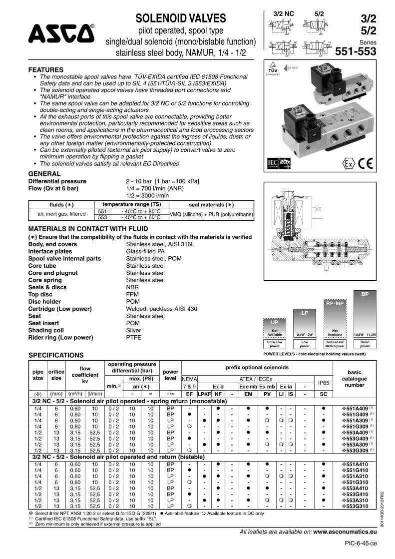
SOLENOID VALVESpilot operated, spool type
single/dual solenoidaluminium body, “NAMUR” style, 1/4 to 1/2
4
3
12
1
2
5
4
53
12 2
14
3
12
1
2
5
10 4
53
12 2
1
14
42
53
12 14
1
3/25/25/3Series
42
53
12 14
1
BP
RP-MP
LP
UP Not
available 0,4W - 2WNot
available 10,5W - 11,2W
Ultra Lowpower
Lowpower
Reduced andMedium power
Basicpower
POWER LEVELS - cold electrical holding values (watt)
551-552-553
8010
9GB
-201
2/R
01

All leafl ets are available on: www.asconumatics.eu
6-40-8
SPECIFICATIONS
pipesize
orifi ce size
fl owcoeffi cient
kv
operating pressure differential (bar) power
level
prefi x optional solenoidsbasic
cataloguenumbermin.(3)
max. (PS) NEMA ATEX / IECEx IP65air () 7 & 9 Ex d Ex e mb Ex mb Ex ia -
() (mm) (m3/h) (l/min) ~ = ~/= EF LPKF NF - EM PV LI IS - SC3/2 NC - 5/2 - Solenoid air pilot operated and return (bistable)1/4 6 0,6 10 0 / 2 10 10 BP - - - - - - 551B4021/4 6 0,6 10 0 / 2 10 10 BP - - - - - - - - - 551H4021/4 6 0,6 10 0 / 2 10 10 LP - - - 551B3021/4 6 0,6 10 0 / 2 10 10 LP - - - - - - - - - 551H3023/8 12 2,49 41,5 0 / 2 10 10 BP - - - - - - 552A4023/8 12 2,49 41,5 0 / 2 10 10 BP - - - - - - - - - 552G4023/8 12 2,49 41,5 0 / 2 10 10 LP - - - 552A3023/8 12 2,49 41,5 0 / 2 10 10 LP - - - - - - - - - 552G3021/2 13 2,49 41,5 0 / 2 10 10 BP - - - - - - 553A4021/2 13 2,49 41,5 0 / 2 10 10 BP - - - - - - - - - 553G4021/2 13 2,49 41,5 0 / 2 10 10 LP - - - 553A3021/2 13 2,49 41,5 0 / 2 10 10 LP - - - - - - - - - 553G302
5/3 - W1 - pressure held, solenoid air pilot operated and return 1/4 6 0,6 10 0 / 2 10 10 BP - - - - - - 551B4651/4 6 0,6 10 0 / 2 10 10 BP - - - - - - - - - 551H4651/4 6 0,6 10 0 / 2 10 10 LP - - - 551B3651/4 6 0,6 10 0 / 2 10 10 LP - - - - - - - - - 551H3653/8 12 2,49 41,5 0 / 2 10 10 BP - - - - - - 552A4653/8 12 2,49 41,5 0 / 2 10 10 BP - - - - - - - - - 552G4653/8 12 2,49 41,5 0 / 2 10 10 LP - - - 552A3653/8 12 2,49 41,5 0 / 2 10 10 LP - - - - - - - - - 552G3651/2 13 2,49 41,5 0 / 2 10 10 BP - - - - - - 553A4651/2 13 2,49 41,5 0 / 2 10 10 BP - - - - - - - - - 553G4651/2 13 2,49 41,5 0 / 2 10 10 LP - - - 553A3651/2 13 2,49 41,5 0 / 2 10 10 LP - - - - - - - - - 553G365
5/3 - W3 - pressure release, solenoid air pilot operated and return 1/4 6 0,6 10 0 / 2 10 10 BP - - - - - - 551B4661/4 6 0,6 10 0 / 2 10 10 BP - - - - - - - - - 551H4661/4 6 0,6 10 0 / 2 10 10 LP - - - 551B3661/4 6 0,6 10 0 / 2 10 10 LP - - - - - - - - - 551H3663/8 12 2,49 41,5 0 / 2 10 10 BP - - - - - - 552A4663/8 12 2,49 41,5 0 / 2 10 10 BP - - - - - - - - - 552G4663/8 12 2,49 41,5 0 / 2 10 10 LP - - - 552A3663/8 12 2,49 41,5 0 / 2 10 10 LP - - - - - - - - - 552G3661/2 13 2,49 41,5 0 / 2 10 10 BP - - - - - - 553A4661/2 13 2,49 41,5 0 / 2 10 10 BP - - - - - - - - - 553G4661/2 13 2,49 41,5 0 / 2 10 10 LP - - - 553A3661/2 13 2,49 41,5 0 / 2 10 10 LP - - - - - - - - - 553G366
Select 8 for NPT ANSI 1.20.3 or select G for ISO G (228/1) ● Available feature Available feature in DC only - Not available(3) Zero minimum is only achieved if external pressure is applied.
SERIES 551-552-553
8010
9GB
-201
2/R
01

All leafl ets are available on: www.asconumatics.eu
6-40-9
PREFIX TABLEprefi x
descriptionpower level
1 2 3 4 5 6 7 LP RP MP BPE F Explosionproof - NEMA 7, 9 - Zinc plated steel conduit - -
E M Waterproof IP67 - Metal enclosure (EN/IEC 60079-7+18, 61241-1)* - -
E T Threaded conduit/hole (M20 x 1,5) - -
I S S C Intrinsically safe with SC coil (EN/IEC 60079-11+26, 61241-11)* - - -
L P K F Flameproof - Aluminium (EN/IEC 60079-1, 61241-1)* - - -N F Flameproof - Aluminium (EN/IEC 60079-1, 61241-1)* - -
P V Encapsulated epoxy moulded (EN/IEC 60079-18, 61241-18)* - -
S C Solenoid with spade plug connector (EN/IEC 60730) - -
W P Waterproof IP67 - Metal enclosure - -
L I I.S. with Aluminium IP67 enclosure (EN/IEC 60079-11 / 61241-1)* - - -W S Waterproof IP67 - 316 SS enclosure - -
W S L P K F Flameproof - 316 SS (EN/IEC 60079-1, 61241-1)* - - -W S E M Waterproof IP67 - 316 SS enclosure (EN/IEC 60079-7+18, 61241-1)* - -
W S N F Flameproof - 316 SS (EN/IEC 60079-1, 61241-1)* - -
T Threaded conduit (1/2" NPT) - -
H T Class H - High temperature - - -
M F Low temperature -40°C (series 551) - -
X Other special constructions - -
* ATEX solenoids are also approved according to EN 13463-1 (non electrical valves)● Available feature Available feature in DC only -Not available
SUFFIX TABLEsuffi x
descriptionpower level
1 2 3 4 5 6 7 LP RP MP BPM O Push type manual operator - -
M Exhaust reducer (series 551 only) - - S L Certifi ed IEC 61508 Functional Safety data (1) - -
Available feature in DC only -Not available (1) Not to use with MO suffi x
OPTIONS & ACCESSORIES
seriespipesize
exhaust protector(stainless steel)
(G) (NPT) (M)551 1/8 34600418 (2) 34600482 (2) -
551 (W1/W3) 1/4 34600419 (2) 34600483 (2) -552 3/8 34600478 (2) 34600480 (2) -553 1/2 34600479 (2) 34600481 (2) -551 M5 - - 34600484
(2) Provided with "SL" suffi x.
PRODUCT SELECTION GUIDESTEP 1Select the fl uid temperature range and seal material from the general table on page 7. Select basic catalogue number, including pipe thread identifi cation letter. Refer to the specifi cations tables on pages 7 and 8.Example : G552A401
STEP 2Select prefix (combination). Select the appropriate operator from the specifi cations table on page 7 and the prefi x table on page 8. Select for this operator in the electrical characteristics table on page 10: the power level (LP, BP), the type of electrical enclosure protection and the desired temperature class.Warning: The ambient temperature range of your application may not exceed the temperature range of your operator.Example : EM
STEP 3Select suffi x (combination) if required. Example : MO
STEP 4Select voltage. Refer to standard voltages on page 10.Example : 230V / 50Hz
STEP 5Final catalogue / ordering number.Example :EM G552A401MO 230 V / 50 Hz
ORDERING EXAMPLES:SC G 551 B 401 230V / 50 HzSC G 551 B 401 SL 230V / 50 HzSC G 551 B 402 MO 230V / 50 Hz
SCHT 8 551 B 402 MO 230V / 50 HzISSC G 553 A 302 MO 24V / DCLPKF G 551 B 301 MO 24V / DC
WSLPKF G 551 B 301 MO 24V / DCISSC G 551 B 301 24V / DC
LI G 552 A 301 24V / DCEM 8 552 A 402 MO 230V / 50 HzEF G 551 H 401 MO 240V / 60 Hz
prefi x (3)
pipe thread voltage
basic number (3) suffi x(3) Prefi xes EF should always be used with the letter H or G in the basic number.
SERIES 551-552-553
8010
9GB
-201
2/R
01
All leafl ets are available on: www.asconumatics.eu
6-40-10
SERIES 551-552-553
EXPLANATION OF TEMPERATURE RANGES OF SOLENOID VALVESValve temperature range The valve temperature range (TS) is determined by the selected seal material, the temperature
range for proper operation of the valve and sometimes by the fluid (e.g. steam)Operator ambient temperature range The operator ambient temperature range is determined by the selected power level and the
safety codeTotal temperature range The temperature range of the complete solenoid valve is determined by the limitations of both
temperature ranges above
ELECTRICAL CHARACTERISTICSCoil insulation class FElectrical safety IEC 335Standard voltages DC (=) 24V - 48V
AC (~) 24V - 48V - 115V - 230V(5)/50Hz; other voltages and 60Hz are available on request
prefi xoption
power ratings operatorambient
temperaturerange (TS)
safety code
electricalenclosureprotection(EN 60529)
replacement coil / kittype
(2)
inrush~
holding~
hot/cold= ~ =
(VA) (VA) (W) (W) (C°)(1) 230 V/50 Hz 24V/DCBasic power (BP)SC 55 23 10,5 9/11,2 -40 to +75 EN 60730 IP65 moulded 400425-117 400425-142 01WP/WS 55 23 10,5 9/11,2 -40 to +75 EN 60730 IP67 steel/SS 400405-117 400405-142 04NF/WSNF 55 23 10,5 - (-60)(7) -40 to +25/40/60 II2G Ex d IIC T6/T5/T4, II2D Ex t IP67 alu./SS 400405-117 - 02NF/WSNF - - - 9/11,2 (-60)(7) -40 to +40/60/75 II2G Ex d IIC T6/T5/T4, II2D Ex t IP67 alu./SS - 400405-142 02EM/WSEM 55 23 10,5 9/11,2 -40 to +40 II2G Ex e mb II T3, II2D Ex tD IP67 steel/SS 400909-117 400913-142 04PV 55 23 10,5 9/11,2 -40 to +65 II2G Ex mb II T3(~)/T4(=),II2D Ex mD 21 IP67 moulded - (4) - (4) 05EF 55 23 10,5 9/11,2 -40 to +54/40 NEMA type 7 and 9 NEMA 4X 238614-058 238714-006 06Low power (LP)
SC 1,5 1,5 1,5 1,7/1,7 -40 to +60 EN 60730 IP65 moulded 400925-097 400925-042 07WP/WS 1,5 1,5 1,5 1,7/1,7 -40 to +60 EN 60730 IP67 steel/SS 400926-097 400926-042 09LPKF/WSLPKF (8) 2,4 2,4 2,4 0,5/0,5 (8) -40 to +80/60 II2G Ex d IIB+H2 Gb T4/T6, II2D Ex t Db IP67 alu./SS - (4) - (4) 13NF/WSNF - - 1,9 - /1,9 (-60)(7) -40 to +75/80 II2G Ex d IIC T6/T5, II2D Ex t IP67 alu./SS - (4) (5) - (4) 08EM/WSEM 1,5 1,5 1,5 1,7/1,7 -40 to +40/55 II2G Ex e mb II T6/T5, II2D Ex tD IP67 steel/SS - (4) - (4) 09PV - - - 1,7/1,7 -40 to +65 II2G Ex mb II T6 / II2D Ex mD 21 IP67 moulded - - (4) 10EF - - - 1,7/1,7 -40 to +60 NEMA type 7 and 9 NEMA 4X - - (4) 11ISSC (3) - - - 0,4/04 -40 to +60 II2G Ex ia IIC T6, II2D Ex iaD 21 IP65 moulded - 268976-001 12LI (3) (6) - - - 0,5/0,5 -40 to +60 II1G Ex ia IIC T6 Ga, II2D Ex t IIIC Db (6) IP67 alu. - - (4) 14
prefi xoption
safety parameters(1) Temperature range can be limited by sealings(2) Refer to the dimensional drawings on pages: 11 to 14(3) ISSC/LI: Check the electrical characteristics in the corresponding catalogue pages(4) Multiple coil kits are available under ATEX/IECEx, contact us(5) (WS)NF: Low Power, 230 V AC does not exist. Maximum voltage in AC is 115 V(6) LI: Low Power, 24 V DC only (For use in zone 0 locations, see the installation conditions given
in the I&M instructions)(7) The certifi ed minimum temperature of this operator(8) LPKF/WSLPKF: 24 V DC, max. ambient temp. +80°C, contact us (48 V DC = 2,1 W)- Not available
UI = (DC) II PI LI CI
(V) (mA) (W) (H) (µF)
Low power (LP)ISSC 32 500 1,5 0 0LI 32 500 1,5 0 0
ELECTRICAL CONNECTIONSprefi x connection
SC, ISSC Spade plug connector with cable gland EN175301-803A (ISO 4400) for cables with an outer diameter from 6 to 10 mm
WP, WS, EM, WSEMM20 cable gland for cables with an outer diameter from 7 to 12 mm. With an internal and external facility for an earthing or bonding conductor
NF, WSNF, LPKF, WSLPKF 1/2" NPT threaded cable entry. Enclosures are supplied without cable glandPV Moulded-in cable, standard length 2 m
LI1/2" NPT cable gland for cables with an outer diameter from 7 to 12 mm. With an internal and external facility for an earthing or bonding conductor
EF 1/2" NPT conduits, standard length 35 cm
8010
9GB
-201
2/R
01
All leafl ets are available on: www.asconumatics.eu
6-40-11
SERIES 551-552-553
Series 551 Series 552-553
179,5225
P
88,7 40
29,1
72,3
==
45=
=
20
49,2
53
42
1 53
1 53
42
3 x V
F D
E
G
A
Q
I
97
1/8
92
45=
=
32 ==
==
188,5
19
3340
24
13
3 51
42
C1C
C2CE
A
3 x 1/4
57
BD
1/8
42
5
Series 551 (W1, W3)
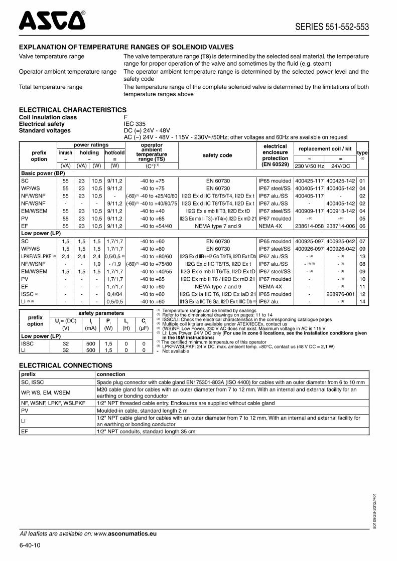
A Interface plates
B 2 mounting holes dia. 5,3; Spotfacing: dia. 9, depth 5 mm
C 1 dia. 5 mm hole for dowel pin (series 551)- in position C1: 3/2 NC function plate
- in position C2: 5/2 function plate
D 2 O-ring seals (supplied)
E Exhaust reducers G 1/8 (series 551) or protectors adaptable on
orifi ces 3 and 5
F 2 mounting holes dia. 6.5 ; Spotfacing: dia. 11, depth 6 mm
G 1 dia. 6,5 mm hole for dowel pin (series 551-552). Same position for interface plate 3/2 NC or 5/2
type I P Q V552 01 à12 111,3 29,6 29,7 3/8553 01 to 12 112,3 31,6 31,8 1/2
82125,5
45=
=
32 ==
==
165
19
3340
24 5
3
3 51
42
42
2 x 1/8
10
C1C
C2CE
A
1 x 1/4
57
BD
1
1/8
ADDITIONAL OPTIONS• Valves confi gured for external pilot air supply, TPL 20547• Other pipe threads are available on request• Ex mb/mD (prefi x "PV") solenoid can be supplied with various cable lengths• Compliance with "UL", "CSA" and other local approvals available on request• 1/2" NPT (prefi x "T") and M20 x 1.5 (prefi x "ET") conduits (aluminium or 316 SS) available for steel solenoid housing• Set of stainless steel mounting screws, catalogue number: 97802212 (series 551)• Set of two exhaust reducers, G1/8, catalogue number: 88100344 (series 551)
INSTALLATION• Multi language installation/maintenance instructions are included with each valve• The solenoid valves can be mounted in any position without affecting operation• 3/2 NC-5/2 spool valve supplied with two interface plates with NAMUR mating surfaces. Depending on function (3/2 NC or
5/2), position one of the two plates on the spool valve body before installing on actuator• Do not connect the pressure supply to the exhaust port 3. The “environmentally-protected” construction is not adapted for NO
function. Contact us for function available in specifi c version• Dowel pin (if necessary), bolts and gaskets are standard supplied• IEC 61508 Functional Safety (suffi x SL), allowable temperature range: -40°C to +60°C. For probability of failure, contact us• It is necessary to connect pipes or fi ttings to the exhaust ports to protect the internal parts of the spool valve and its pneumatic
operator if used outside or in harsh environments (dusts, liquids etc.)• Threaded pipe connection identifi er is: 8 = NPT (ANSI 1.20.3); G = G (ISO 228/1)• Prefi x "NF/WSNF" enclosure is provided with a 1/2" NPT threaded entry hole, M20 x 1,5 (prefi x "ET") is optional. Both are sup-
plied without cable gland• To comply with IEC 61508 (SIL) the valves must be provided with a specifi c exhaust protector (see following pages)
DIMENSIONS (mm), WEIGHT (kg)
8010
9GB
-201
1/R
01

All leafl ets are available on: www.asconumatics.eu
6-40-12
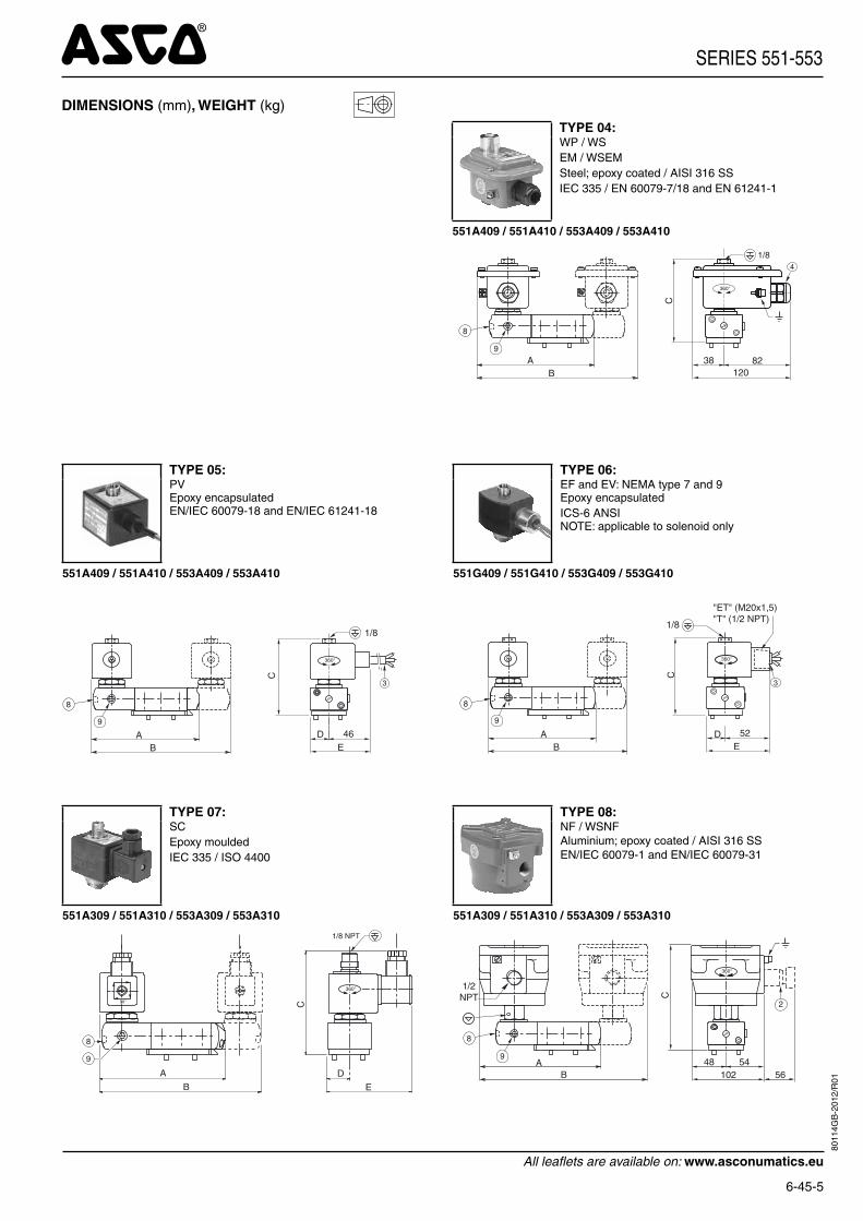
DIMENSIONS (mm), WEIGHT (kg)
TYPE 01: SCEpoxy mouldedIEC 335 / ISO 4400
TYPE 02: NF / WSNFAluminium; epoxy coated / AISI 316 SS EN/IEC 60079-1 and EN/IEC 60079-31
551B401/B402/B401MO/B402MO/B465/B466/B465MO/B466MO552A401/A402/A401MO/A402MO/A465/A466/A465MO/A466MO553A401/A402/A401MO/A402MO/A465/A466/A465MO/A466MO
551B401/B402/B401MO/B402MO/B465/B466/B465MO/B466MO552A401/A402/A401MO/A402MO/A465/A466/A465MO/A466MO553A401/A402/A401MO/A402MO/A465/A466/A465MO/A466MO
90° C
AB
DE
8
9
360°
6
1/8
48 54102
AB
C
360°
1/2NPT
8
9
2
56
TYPE 04: WP / WSEM / WSEMSteel; epoxy coated / AISI 316 SS IEC 335 / EN 60079-7/18 and EN 61241-1
551B401/B402/B401MO/B402MO/B465/B466/B465MO/B466MO552A401/A402/A401MO/A402MO/A465/A466/A465MO/A466MO553A401/A402/A401MO/A402MO/A465/A466/A465MO/A466MO
38 82120
AB
C
4
360°
1/8
8
9
TYPE 05:PVEpoxy encapsulatedEN/IEC 60079-18 and EN/IEC 61241-18
TYPE 06: EF: NEMA type 7 and 9Epoxy encapsulatedICS-6 ANSINOTE: applicable to solenoid only
551B401/B402/B401MO/B402MO/B465/B466/B465MO/B466MO552A401/A402/A401MO/A402MO/A465/A466/A465MO/A466MO553A401/A402/A401MO/A402MO/A465/A466/A465MO/A466MO
551H401/H402/H401MO/H402MO/H465/H466/H465MO/H466MO552G401/G402/G401MO/G402MO/G465/G466/G465MO/G466MO553G401/G402/G401MO/G402MO/G465/G466/G465MO/G466MO
AB
C
1/8
3
360°
D 46E
8
9A
B
C
1/8
3
360°
D 52E
8
9
SERIES 551-552-553
8010
9GB
-201
2/R
01

All leafl ets are available on: www.asconumatics.eu
6-40-13
DIMENSIONS (mm), WEIGHT (kg)
TYPE 07: SCEpoxy mouldedIEC 335 / ISO 4400
TYPE 08:NF / WSNFAluminium; epoxy coated / AISI 316 SSEN/IEC 60079-1 and EN/IEC 60079-31
551B301/B302/B301MO/B302MO/B365/B366/B365MO/B366MO552A301/A302/A301MO/A302MO/A365/A366/A365MO/A366MO553A301/A302/A301MO/A302MO/A365/A366/A365MO/A366MO
551B301/B302/B301MO/B302MO/B365/B366/B365MO/B366MO552A301/A302/A301MO/A302MO/A365/A366/A365MO/A366MO553A301/A302/A301MO/A302MO/A365/A366/A365MO/A366MO
90° C
AB
DE
1/8 NPT
8
9
360°
48 54102
AB
C
360°
1/2NPT
8
9
2
56
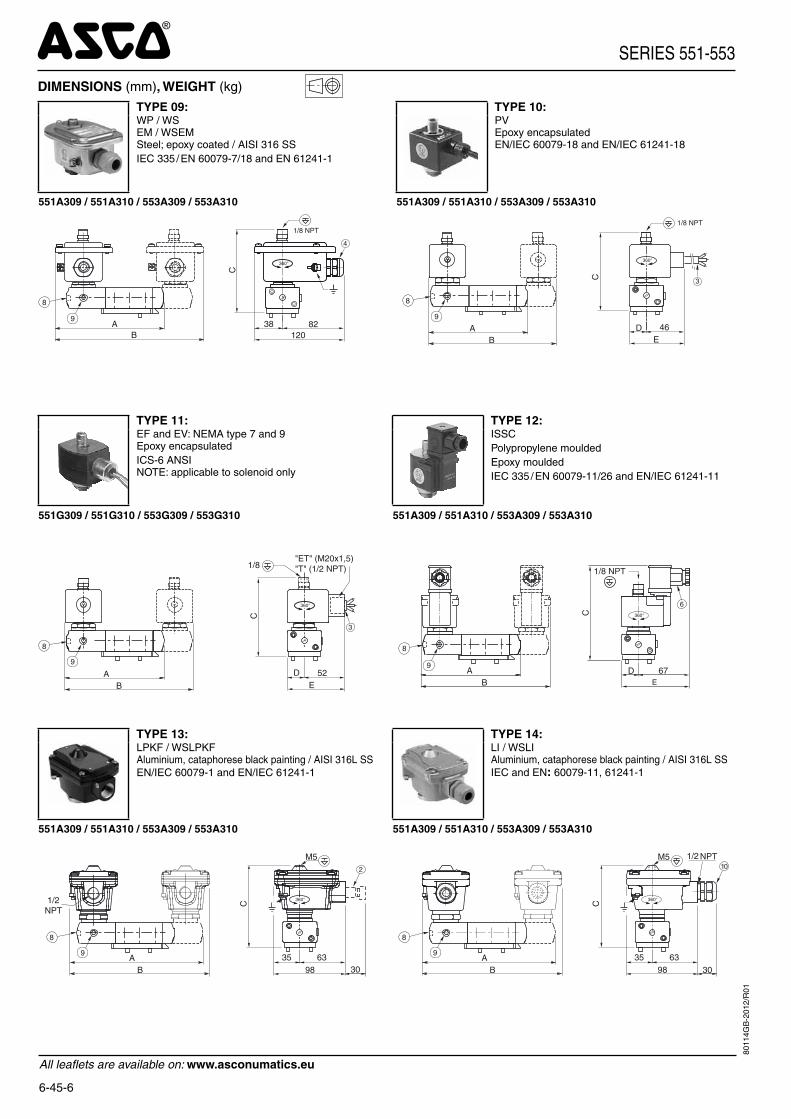
TYPE 09:WP / WSEM / WSEMSteel; epoxy coated / AISI 316 SS IEC 335 / EN 60079-7/18 and EN 61241-1
TYPE 10:PVEpoxy encapsulatedEN/IEC 60079-18 and EN/IEC 61241-18
551B301/B302/B301MO/B302MO/B365/B366/B365MO/B366MO552A301/A302/A301MO/A302MO/A365/A366/A365MO/A366MO553A301/A302/A301MO/A302MO/A365/A366/A365MO/A366MO
551B301/B302/B301MO/B302MO/B365/B366/B365MO/B366MO552A301/A302/A301MO/A302MO/A365/A366/A365MO/A366MO553A301/A302/A301MO/A302MO/A365/A366/A365MO/A366MO
38 82120
AB
C
4
360°
8
9
1/8 NPT
AB
C
3
360°
D 46E
8
9
1/8 NPT
TYPE 11:EF: NEMA type 7 and 9Epoxy encapsulatedICS-6 ANSINOTE: applicable to solenoid only
TYPE 12:ISSCPolypropylene mouldedEpoxy mouldedIEC 335 / EN 60079-11/26 and EN/IEC 61241-11
551H301/H302/H301MO/H302MO/H365/H366/H365MO/H366MO552G301/G302/G301MO/G302MO/G365/G366/G365MO/G366MO553G301/G302/G301MO/G302MO/G365/G366/G365MO/G366MO
551B301/B302/B301MO/B302MO/B365/B366/B365MO/B366MO552A301/A302/A301MO/A302MO/A365/A366/A365MO/A366MO553A301/A302/A301MO/A302MO/A365/A366/A365MO/A366MO
AB
8
9
C
3
360°
D 52E
1/8
D 67EB
A
C
6
1/8 NPT
360°
9
8
SERIES 551-552-553
8010
9GB
-201
2/R
01
All leafl ets are available on: www.asconumatics.eu
6-40-14
SERIES 551-552-553
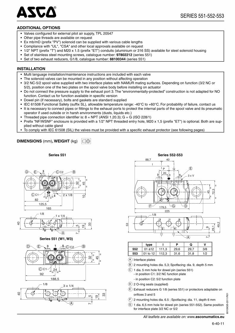
2 Ex d certifi ed cable gland (on request)3 Three-core cable, length 2 m4 Cable gland for unarmoured cable with 7 to 12 mm dia. sheath6 Connector rotatable by 90° increments, cable Ø 6 - 10 mm
8 Push type or screw type manual operator, suffi x MO9 External pilot air supply, 1/8 pipe size10 Cable gland for unarmoured cable with 7 to 12 mm dia. sheath
Connectable pilot exhaust port Non-connectable pilot exhaust port
type prefi x option
plage depuis-sance
A B C D Eweight (1)
monostable 5/2 bistable - 5/3
551 552/553 551 551
(W1-W3)552/553 551 552/
553 551 552/553 551 552/
553 551 552 553 551 552 553
01 SC BP 125 179,5 174 198,5 225 107,7 121,2 22,5 36,15 86,5 100,2 0,86 1,76 1,66 1,37 2,32 2,2202 NF / WSNF BP 152 224,3 218 241,5 314,6 146,8 160,3 - - - - 1,90 2,80 2,70 3,45 4,46 4,3604 WP / WS BP 142 196,2 198 221,5 258,3 108 121,5 - - - - 0,89 1,77 1,67 1,43 2,34 2,2404 (WS)EM BP 142 196,2 198 221,5 258,3 108 121,5 - - - - 0,89 1,77 1,67 1,43 2,34 2,2405 PV BP 126 179,5 166 189,5 225 93 106,5 22,5 36,15 67,5 81,2 0,87 1,77 1,67 1,39 2,33 2,2306 EF BP 126,5 183 167 190,5 232 90,5 104 22,5 36,15 74,5 88,2 0,88 1,77 1,67 1,40 2,34 2,2407 SC LP 126,5 180,5 167 190,5 227 106,5 120 22,5 36,15 87,5 101,2 0,86 1,97 1,87 1,61 2,53 2,4308 NF / WSNF LP 152 224,3 218 241,5 314,6 146,8 160,3 - - - - 1,90 2,80 2,70 3,45 4,46 4,3609 WP/WS/(WS)EM LP 142 196,2 198 221,5 258,3 107,2 120,7 - - - - 1,10 1,98 1,88 1,43 2,55 2,4510 PV LP 126 179,5 166 189,5 225 105,5 119 22,5 36,15 67,5 81,2 1,08 1,98 1,88 1,60 2,54 2,4411 EF LP 126,5 183 167 190,5 232 105,5 119 22,5 36,15 74,5 88,2 1,07 1,98 1,88 1,59 2,55 2,4512 ISSC LP 116 182 169 192,5 230 129,5 143 22,5 36,15 89,5 103,5 0,90 1,80 1,70 1,46 2,36 2,2613 LPKF LP 135 191,5 186 152,5 249 118 131,5 - - - - 1,00 2,17 2,07 1,65 2,62 2,5213 WSLPKF LP 135 191,5 186 152,5 249 118 131,5 - - - - 1,61 2,77 3,08 2,85 3,82 3,5914 LI LP 135 191,5 186 152,5 249 118 131,5 - - - - 1,01 2,18 2,08 1,66 2,63 2,53
(1) Including coil(s) and connector(s).
ACCESSORIES
ø14
ø14
20
1/8NPT
1/8 NPT
1/4 NPT
B
ØA
ØA M5 1/8 1/4 3/8 1/2B 4,5 10 11 11 14
Pilot exhaustprotectorpart no.
276405-001
Pilot top exhaust low power(ASCO solenoid interface)
exhaust protector(stainless steel)
TYPE 13 :LPKF / WSLPKFAluminium, cataphorese black painting / AISI 316L SSEN/IEC 60079-1 and EN/IEC 61241-1
TYPE 14 :LIAluminium, cataphorese black paintingIEC and EN: 60079-11, 61241-1
551B301/B302/B301MO/B302MO/B365/B366/B365MO/B366MO552A301/A302/A301MO/A302MO/A365/A366/A365MO/A366MO553A301/A302/A301MO/A302MO/A365/A366/A365MO/A366MO
551B301/B302/B301MO/B302MO/B365/B366/B365MO/B366MO552A301/A302/A301MO/A302MO/A365/A366/A365MO/A366MO553A301/A302/A301MO/A302MO/A365/A366/A365MO/A366MO
35 6398
AB
C1/2NPT
8
9
M52
30
360°
35 6398
AB
C
8
9
M5
360°
1/2 NPT
30
10
DIMENSIONS (mm), WEIGHT (kg)
PIC
-06-
0040
-GB
--
Ava
ilabi
lity,
des
ign
and
spec
ifi ca
tions
are
sub
ject
to c
hang
e w
ithou
t not
ice.
All
right
s re
serv
ed.
8010
9GB
-201
2/R
01

All leafl ets are available on: www.asconumatics.eu
PIC-6-43-GB
FEATURES• The monostable spool valves have TÜV certifi ed IEC 61508 Functional Safety
data and can be used up to SIL 4• The solenoid operated spool valves have threaded port connections and NAMUR
interface• The same spool valve can be adapted for 3/2 NC or 5/2 functions for controlling
double-acting and single-acting actuators• All the exhaust ports of this spool valve are connectable, providing better
environmental protection, particularly recommended for sensitive areas such as clean rooms, and applications in the pharmaceutical and food processing sectors
• The valve offers environmental protection against the ingress of liquids, dusts or any other foreign matter (environmentally-protected construction)
• Can be externally piloted (external air pilot supply) to convert valve to zero minimum operation by fl ipping a gasket
• The solenoid valves satisfy all relevant EC Directives
GENERALDifferential pressure 2 - 10 bar [1 bar =100 kPa]Flow (Qv at 6 bar) 700 l/min (ANR)
fl uids () temperature range (TS) seal materials ()air, inert gas, fi ltered - 40°C to + 60°C VMQ (silicone) + PUR (polyurethane)
MATERIALS IN CONTACT WITH FLUID() Ensure that the compatibility of the fl uids in contact with the materials is verifi edBody, end covers BrassSpool valve internal parts Brass, stainless steel, POMInterface plates Glass-fi lled PACore tube Stainless steelCore and plugnut Stainless steelCore spring Stainless steelSeals & discs NBR Top disc PADisc holder POMCartridge (Low power) Welded, packless AISI 430Seat BrassSeat insert POMShading coil CopperRider ring (Low power) PTFE
SPECIFICATIONS
pipesize
orifi cesize
fl owcoeffi cient
kv
operating pressuredifferential (bar) power
level
prefi x optional solenoidsbasic
cataloguenumbermin.(2)
max. (PS) NEMA ATEX / IECExIP65
air () 7 & 9 Ex d Ex e mb Ex mb Ex ia -() (mm) (m3/h) (l/min) ~ = ~/= EF LPKF NF - EM PV LI IS - SC
3/2 NC - 5/2 - Solenoid air pilot operated - spring return (monostable)1/4 6 0,6 10 0 / 2 10 10 BP - - - - - - 551A403 (1)
1/4 6 0,6 10 0 / 2 10 10 BP - - - - - - - - - 551G403 (1)
1/4 6 0,6 10 0 / 2 10 10 LP - - - 551A303 (1)
1/4 6 0,6 10 0 / 2 10 10 LP - - - - - - - - - 551G303 (1)
3/2 NC - 5/2 - Solenoid air pilot operated and return (bistable)1/4 6 0,6 10 0 / 2 10 10 BP - - - - - - 551A4041/4 6 0,6 10 0 / 2 10 10 BP - - - - - - - - - 551G4041/4 6 0,6 10 0 / 2 10 10 LP - - - 551A3041/4 6 0,6 10 0 / 2 10 10 LP - - - - - - - - - 551G304
Select 8 for NPT ANSI 1.20.3 or select G for ISO G (228/1) ● Available feature Available feature in DC only. (1) Certifi ed IEC 61508 Functional Safety data, use suffi x "SL". (2) Zero minimum is only achieved if external pressure is applied.
BP
RP-MP
LP
UP Not
Available 0,4W - 2WNot
Available 10,5W - 11,2W
Ultra Lowpower
Lowpower
Reduced andMedium power
Basicpower
POWER LEVELS - cold electrical holding values (watt)
SOLENOID VALVESpilot operated, spool type
single/dual solenoid (mono/bistable function)brass body, NAMUR, 1/4
3/2 NC 5/24
3
12
1
2
5
4
53
12 2
11
4
3
12
1
2
5
104
53
12 2
1
14
3/25/2Series
551
8011
2GB
-201
2/R
01

All leafl ets are available on: www.asconumatics.eu
6-43-2
PREFIX TABLEprefi x
descriptionpower level
1 2 3 4 5 6 7 LP RP MP BPE F Explosionproof - NEMA 7, 9 - Zinc plated steel conduit - - E V Explosionproof - NEMA 7, 9 - 316 SS conduit - - E M Waterproof IP67 - Metal enclosure (EN/IEC 60079-7+18, 61241-1)* - -
E T Threaded conduit/hole (M20 x 1,5) - - I S S C Intrinsically safe with SC coil (EN/IEC 60079-11+26, 61241-11)* - - -L P K F Flameproof - Aluminium (EN/IEC 60079-1, 61241-1)* - - -N F Flameproof - Aluminium (EN/IEC 60079-1, 60079-31)* - - P V Encapsulated epoxy moulded (EN/IEC 60079-18, 61241-18)* - - S C Solenoid with spade plug connector (EN/IEC 60730) - - W P Waterproof IP67 - Metal enclosure - - L I I.S. with Aluminium IP67 enclosure (EN/IEC 60079-11 / 61241-1)* - - -W S Waterproof IP67 - 316 SS enclosure - - W S L P K F Flameproof - 316 SS (EN/IEC 60079-1, 61241-1)* - - -W S E M Waterproof IP67 - 316 SS enclosure (EN/IEC 60079-7+18, 61241-1)* - - W S L I I.S. with 316L SS IP67 enclosure (EN/IEC 60079-11, 61241-1)* - - -W S N F Flameproof - 316 SS (EN/IEC 60079-1, 60079-31)* - -
T Threaded conduit (1/2" NPT) - - H T Class H - High temperature, +80°C ambient temp. - - -
X Other special constructions - -
SUFFIX TABLEsuffi x
descriptionpower level
1 2 3 4 5 6 7 LP RP MP BPM O Push type manual operator / - -
S L Certifi ed IEC 61508 Functional Safety data (2) / - -
OPTIONS & ACCESSORIES
seriespipesize
exhaustprotector
(stainless steel)
551G 1/8 34600418 (1)
NPT 1/8 34600482 (1)
M5 34600484 (1)
Available feature Available feature in DC only - Not available * ATEX solenoids are also approved according to EN 13463-1 (non electrical valves) (1) Provided with "SL" suffi x (2) Not to use with MO suffi x
SERIES 551
PRODUCT SELECTION GUIDESTEP 1Select the fl uid temperature range and seal material from the general table on page 1. Select basic catalogue number, including pipe thread identification letter. Refer to the specifi cations table above.Example : G551A403
STEP 2Select prefix (combination). Select the appropriate operator from the specifi cations table on page 1 and the prefi x table on page 2. Select for this operator in the electrical characteristics table on page 3: the power level (LP, BP), the type of electrical enclosure protection and the desired temperature class.Warning: The ambient temperature range of your application may not exceed the temperature range of your operator.Example : EM
STEP 3Select suffi x (combination) if required. Example : MO
STEP 4Select voltage. Refer to standard voltages on page 3.Example : 230V / 50Hz
STEP 5Final catalogue / ordering number.Example :EM G551A403MO 230 V / 50 Hz
ORDERING EXAMPLES:SC G 551 A 403 230V / 50 HzSC G 551 A 403 SL 230V / 50 HzSC G 551 A 404 MO 230V / 50 Hz
SCHT 8 551 A 404 MO 230V / 50 HzISSC G 551 A 404 MO 24V / DC
WSLPKF G 551 A 303 MO 24V / DCLPKF G 551 A 303 MO 24V / DCLPKF G 551 A 303 MO 230V / 50 Hz
LI G 551 A 307 24V / DCWSLI G 551 A 308 MO 24V / DCLPKF G 551 A 303 MO 24V / DC
EM 8 551 A 403 MO 230V / 50 HzEF G 551 G 403 MO 240V / 60 Hz
prefi x (3)
pipe thread voltage
basic number (3) suffi x(3) Prefi xes EF and EV should always be used with the letter G in the basic
number.
8011
2GB
-201
2/R
01

All leafl ets are available on: www.asconumatics.eu
6-43-3
SERIES 551
EXPLANATION OF TEMPERATURE RANGES OF SOLENOID VALVESValve temperature range The valve temperature range (TS) is determined by the selected seal material, the temperature
range for proper operation of the valve and sometimes by the fluid (e.g. steam)Operator ambient temperature range The operator ambient temperature range is determined by the selected power level and the
safety codeTotal temperature range The temperature range of the complete solenoid valve is determined by the limitations of both
temperature ranges above
ELECTRICAL CHARACTERISTICSCoil insulation class FElectrical safety IEC 335Standard voltages DC (=) 24V - 48V
AC (~) 24V - 48V - 115V - 230V(5)/50Hz; other voltages and 60Hz are available on request
prefi xoption
power ratings operatorambient
temperaturerange (TS)
safety code
electricalenclosureprotection(EN 60529)
replacement coil / kittype
(2)
inrush~
holding~
hot/cold= ~ =
(VA) (VA) (W) (W) (C°)(1) 230 V/50 Hz 24V/DCBasic power (BP)SC 55 23 10,5 9/11,2 -40 to +75 EN 60730 IP65 moulded 400425-117 400425-142 01WP/WS 55 23 10,5 9/11,2 -40 to +75 EN 60730 IP67 steel/SS 400405-117 400405-142 04NF/WSNF 55 23 10,5 - (-60)(7) -40 to +25/40/60 II2G Ex d IIC T6/T5/T4, II2D Ex t IP67 alu./SS 400405-117 - 02NF/WSNF - - - 9/11,2 (-60)(7) -40 to +40/60/75 II2G Ex d IIC T6/T5/T4, II2D Ex t IP67 alu./SS - 400405-142 02EM/WSEM 55 23 10,5 9/11,2 -40 to +40 II2G Ex e mb II T3, II2D Ex tD IP67 steel/SS 400909-117 400913-142 04PV 55 23 10,5 9/11,2 -40 to +65 II2G Ex mb II T3(~)/T4(=),II2D Ex mD 21 IP67 moulded - (4) - (4) 05EF/EV 55 23 10,5 9/11,2 -40 to +54/40 NEMA type 7 and 9 NEMA 4X 238614-058 238714-006 06Low power (LP)SC 1,5 1,5 1,5 1,7/1,7 -40 to +60 EN 60730 IP65 moulded 400925-097 400925-042 07WP/WS 1,5 1,5 1,5 1,7/1,7 -40 to +60 EN 60730 IP67 steel/SS 400926-097 400926-042 09LPKF/WSLPKF (8) 2,4 2,4 2,4 0,5/0,5 (8) -40 to +80/60 II2G Ex d IIB+H2 Gb T4/T6, II2D Ex t Db IP67 alu./SS - (4) - (4) 13NF/WSNF - - 1,9 - /1,9 (-60)(7) -40 to +75/80 II2G Ex d IIC T6/T5, II2D Ex t IP67 alu./SS - (4) (5) - (4) 08EM/WSEM 1,5 1,5 1,5 1,7/1,7 -40 to +40/55 II2G Ex e mb II T6/T5, II2D Ex tD IP67 steel/SS - (4) - (4) 09PV - - - 1,7/1,7 -40 to +65 II2G Ex mb II T6 / II2D Ex mD 21 IP67 moulded - - (4) 10EF/EV - - - 1,7/1,7 -40 to +60 NEMA type 7 and 9 NEMA 4X - - (4) 11ISSC (3) - - - 0,4/04 -40 to +60 II1G Ex ia IIC T6, II2D Ex iaD 21 IP65 moulded - 268976-001 12LI (3) (6) - - - 0,5/0,5 -40 to +60 II1G Ex ia IIC T6 Ga, II2D Ex t IIIC Db (6) IP67 alu. - - (4) 14WSLI (3) (6) - - - 0,5/0,5 -40 to +60 II1G Ex ia IIC Ga T6, II2D Ex t IIIC Db IP67 SS - - (4) 14
prefi xoption
safety parameters(1) Temperature range can be limited by sealings(2) Refer to the dimensional drawings on pages: 4 to 7(3) ISSC/LI/WSLI: Check the electrical characteristics in the corresponding catalogue pages(4) Multiple coil kits are available under ATEX/IECEx, contact us(5) (WS)NF: Low Power, 230 V AC does not exist. Maximum voltage in AC is 115 V(6) LI/WSLI: Low Power, 24 V DC only (LI: For use in zone 0 locations, see the installation
conditions given in the I&M instructions)(7) The certifi ed minimum temperature of this operator(8) LPKF/WSLPKF: 24 V DC, max. ambient temp. +80°C, contact us (48 V DC = 2,1 W)- Not available
UI = (DC) II PI LI CI
(V) (mA) (W) (H) (µF)
Low power (LP)ISSC 32 500 1,5 0 0LI/WSLI 32 500 1,5 0 0
ELECTRICAL CONNECTIONSprefi x connection
SC, ISSC Spade plug connector with cable gland EN175301-803A (ISO 4400) for cables with an outer diameter from 6 to 10 mm
WP, WS, EM, WSEM M20 cable gland for cables with an outer diameter from 7 to 12 mm. With an internal and external facility for an earthing or bonding conductor
NF, WSNF, LPKF, WSLPKF 1/2" NPT threaded cable entry. Enclosures are supplied without cable glandPV Moulded-in cable, standard length 2 m
LI, WSLI 1/2" NPT cable gland for cables with an outer diameter from 7 to 12 mm. With an internal and external facility for an earthing or bonding conductor
EF, EV 1/2" NPT conduits, standard length 35 cm
8011
2GB
-201
2/R
01

All leafl ets are available on: www.asconumatics.eu
6-43-4
SERIES 551
ADDITIONAL OPTIONS• Valves confi gured for external pilot air supply, TPL 20547• Other pipe threads are available on request• Ex mb/mD (prefi x "PV") solenoid can be supplied with various cable lengths• Compliance with "UL", "CSA" and other local approvals available on request• 1/2" NPT (prefi x "T") and M20 x 1.5 (prefi x "ET") conduits (aluminium or 316 SS) available for steel solenoid housing• Set of stainless steel mounting screws, catalogue number: 97802212 (series 551)• Set of two exhaust reducers, G1/8, catalogue number: 88100344 (series 551)
INSTALLATION• Multi language installation/maintenance instructions are included with each valve• The solenoid valves can be mounted in any position without affecting operation• 3/2 NC-5/2 spool valve supplied with two interface plates with NAMUR mating surfaces. Depending on function (3/2 NC or
5/2), position one of the two plates on the spool valve body before installing on actuator• Do not connect the pressure supply to the exhaust port 3. The “environmentally-protected” construction is not adapted for NO
function. Contact us for function available in specifi c version• Dowel pin (if necessary), bolts and gaskets are standard supplied• IEC 61508 Functional Safety (suffi x SL), allowable temperature range: -40°C to +60°C. For probability of failure, contact us• It is necessary to connect pipes or fi ttings to the exhaust ports to protect the internal parts of the spool valve and its pneumatic
operator if used outside or in harsh environments (dusts, liquids etc.)• Threaded pipe connection identifi er is: 8 = NPT (ANSI 1.20.3); G = G (ISO 228/1)• Prefi x "NF/WSNF" enclosure is provided with a 1/2" NPT threaded entry hole, M20 x 1,5 (prefi x "ET") is optional. Both are supplied without cable gland• To comply with IEC 61508 (SIL) the valves must be provided with a specifi c exhaust protector (see following pages)
DIMENSIONS (mm), WEIGHT (kg)
All types
82125,5
45=
=
32 ==
==
165
19
3340
24 5
3
3 51
42
42
2 x 1/8 7C1C
C2CE
A
1 x 1/4
57
BD
1
1/8
A Interface plates
B 2 mounting holes: 5,3 mm dia. (Spotfacing: 9 mm dia., depth 5 mm)
2 screws (CHc M5 x 35), engaged length: 7 mm
C One 5 mm dia. hole for dowel pin:
- in position C1: 3/2 NC function plate
- in position C2: 5/2 function plate
D 2 O-ring seals (supplied)
TYPE 01: TYPE 02:SCEpoxy mouldedIEC 335 / ISO 440
NF / WSNFAluminium; epoxy coated / AISI 316 SSEN/IEC 60079-1 and EN/IEC 60079-31
551A403 / 551A404 551A403 / 551A404
90° C
AB
DE
8
9
360°
6 1/8
48 54102
AB
C
360°
1/2NPT
8
9
2
56
8011
2GB
-201
2/R
01

All leafl ets are available on: www.asconumatics.eu
6-43-5
SERIES 551
DIMENSIONS (mm), WEIGHT (kg)
TYPE 04:WP / WSEM / WSEMAcier; revêtement époxy / Acier inox AISI 316 CEI 335 / EN 60079-7/18 et EN 61241-1
551A403 / 551A404
38 82120
AB
C
4
360°
1/8
8
9
TYPE 05: TYPE 06:PVEpoxy encapsulatedEN/IEC 60079-18 and EN/IEC 61241-18
EF and EV: NEMA type 7 and 9Epoxy encapsulatedICS-6 ANSINOTE: applicable to solenoid only
551A403 / 551A404 551G403 / 551G404
AB
C
1/8
3
360°
D 46E
8
9A
B
C
1/8
3
360°
D 52E
8
9
"ET" (M20x1,5)"T" (1/2 NPT)
TYPE 07: TYPE 08:SCEpoxy mouldedIEC 335 / ISO 4400
NF / WSNFAluminium; epoxy coated / AISI 316 SSEN/IEC 60079-1 and EN/IEC 60079-31
551A303 / 551A304 551A303 / 551A304
90° C
AB
DE
1/8 NPT
8
9
360°
48 54102
AB
C
360°
1/2NPT
8
9
2
56
8011
2GB
-201
2/R
01

All leafl ets are available on: www.asconumatics.eu
6-43-6
SERIES 551
DIMENSIONS (mm), WEIGHT (kg)
TYPE 09: TYPE 10:WP / WSEM / WSEMSteel; epoxy coated / AISI 316 SS IEC 335 / EN 60079-7/18 and EN 61241-1
PVEpoxy encapsulatedEN/IEC 60079-18 and EN/IEC 61241-18
551A303 / 551A304 551A303 / 551A304
38 82120
AB
C
4
360°
8
9
1/8 NPT
AB
C
3
360°
D 46E
8
9
1/8 NPT
TYPE 11: TYPE 12:EF and EV: NEMA type 7 and 9Epoxy encapsulatedICS-6 ANSINOTE: applicable to solenoid only
ISSCPolypropylene mouldedEpoxy mouldedIEC 335 / EN 60079-11/26 and EN/IEC 61241-11
551G303 / 551G304 551G403 / 551G404
AB
8
9
C
3
360°
D 52E
1/8"ET" (M20x1,5)"T" (1/2 NPT)
D 67EB
A
C
6
1/8 NPT
360°
9
8
TYPE 13: TYPE 14:LPKF / WSLPKFAluminium / AISI 316 SSEN/IEC 60079-1 and EN/IEC 61241-1
LI / WSLIAluminium, cataphorese black painting / AISI 316L SSIEC and EN: 60079-11, 61241-1
551A303 / 551A304 551A303 / 551A304
35 6398
AB
C1/2NPT
8
9
M52
30
360°
35 6398
AB
C
8
9
M5
360°
1/2 NPT
30
10
8011
2GB
-201
2/R
01

All leafl ets are available on: www.asconumatics.eu
6-43-7
type prefi x option power level A B C D Eweight (1)
monostable bistable01 SC basic power 144 182 107,7 22,5 86,5 1,45 1,9602 NF basic power 170 236 146,8 - - 2,49 4,2502 WSNF basic power 170 236 146,8 - - 3,79 5,5504 WP/WS/EM/WSEM basic power 160 216 108 - - 1,62 2,2305 PV basic power 144 184 93 22,5 67,5 1,46 2,1906 EF / EV basic power 144,5 185 90,5 22,5 74,5 1,47 2,2007 SC low power 144,5 185 106,5 22,5 87,5 1,45 2,4108 NF low power 170 236 146,8 - - 2,49 4,2508 WSNF low power 170 236 146,8 - - 3,79 5,5509 WP / WS / EM / WSEM low power 160 216 107,2 - - 1,69 2,2310 PV low power 144 184 105,5 22,5 67,5 1,67 2,4011 EF / EV low power 144,5 185 105,5 22,5 74,5 1,66 2,3912 ISSC low power 134 187 129,5 22,5 89,5 1,70 2,2613 LPKF low power 135 186 118 - - 1,00 1,6513 WSLPKF low power 135 186 118 - - 1,61 2,8514 LI low power 135 186 118 - - 1,01 1,6614 WSLI low power 135 186 118 - - 1,62 2,86
(1) Incl. coil(s) and connector(s)
2 Ex d certifi ed cable gland (on request)
3 Three-core cable, length 2 m
4 Cable gland for unarmoured cable with 7 to 12 mm dia. sheath
6 Connector rotatable by 90° increments ( cable Ø 6 - 10 mm)
8 Push type or screw type manual operator, suffi x MO
9 External pilot air supply, 1/8 pipe size
10 Cable gland for unarmoured cable with 7 to 12 mm dia. sheath
Connectable pilot exhaust port
Non-connectable pilot exhaust port
ACCESSORIESø14
ø14
20
1/8NPT
1/8 NPT
1/4 NPT
pilot exhaust protector
part number276405-001
pilot top exhaust low power (ASCO solenoid interface)
B
ØA
ØA M5 1/8 -
B 4,5 10 -
exhaust protector(stainless steel)
DIMENSIONS (mm), WEIGHT (kg)
SERIES 551
8011
2GB
-201
2/R
01
All leafl ets are available on: www.asconumatics.eu
PIC-6-45-GB
FEATURES• The monostable spool valves have TÜV-EXIDA certifi ed IEC 61508 Functional
Safety data and can be used up to SIL 4 (551/TÜV)-SIL 3 (553/EXIDA)• The solenoid operated spool valves have threaded port connections and
"NAMUR" interface• The same spool valve can be adapted for 3/2 NC or 5/2 functions for controlling
double-acting and single-acting actuators• All the exhaust ports of this spool valve are connectable, providing better
environmental protection, particularly recommended for sensitive areas such as clean rooms, and applications in the pharmaceutical and food processing sectors
• The valve offers environmental protection against the ingress of liquids, dusts or any other foreign matter (environmentally-protected construction)
• Can be externally piloted (external air pilot supply) to convert valve to zero minimum operation by fl ipping a gasket
• The solenoid valves satisfy all relevant EC Directives
GENERALDifferential pressure 2 - 10 bar [1 bar =100 kPa]Flow (Qv at 6 bar) 1/4 = 700 l/min (ANR) 1/2 = 3000 l/min
fl uids () temperature range (TS) seal materials ()
air, inert gas, fi ltered 551 : - 40°C to + 80°C VMQ (silicone) + PUR (polyurethane)553 : - 40°C to + 60°C
MATERIALS IN CONTACT WITH FLUID() Ensure that the compatibility of the fl uids in contact with the materials is verifi edBody, end covers Stainless steel, AISI 316LInterface plates Glass-fi lled PASpool valve internal parts Stainless steel, POMCore tube Stainless steelCore and plugnut Stainless steelCore spring Stainless steelSeals & discs NBR Top disc FPMDisc holder POMCartridge (Low power) Welded, packless AISI 430Seat Stainless steelSeat insert POMShading coil SilverRider ring (Low power) PTFE
SPECIFICATIONS
pipesize
orifi cesize
fl owcoeffi cient
kv
operating pressuredifferential (bar) power
level
prefi x optional solenoidsbasic
cataloguenumbermin.(2)
max. (PS) NEMA ATEX / IECExIP65
air () 7 & 9 Ex d Ex e mb Ex mb Ex ia -() (mm) (m3/h) (l/min) ~ = ~/= EF LPKF NF - EM PV LI IS - SC
3/2 NC - 5/2 - Solenoid air pilot operated - spring return (monostable)1/4 6 0,60 10 0 / 2 10 10 BP - - - - - - 551A409 (1)
1/4 6 0,60 10 0 / 2 10 10 BP - - - - - - - - - 551G409 (1)
1/4 6 0,60 10 0 / 2 10 10 LP - - - 551A309 (1)
1/4 6 0,60 10 0 / 2 10 10 LP - - - - - - - - - 551G309 (1)
1/2 13 3,15 52,5 0 / 2 10 10 BP - - - - - - 553A409 (1)
1/2 13 3,15 52,5 0 / 2 10 10 BP - - - - - - - - - 553G409 (1)
1/2 13 3,15 52,5 0 / 2 10 10 LP - - - 553A309 (1)
1/2 13 3,15 52,5 0 / 2 10 10 LP - - - - - - - - - 553G309 (1)
3/2 NC - 5/2 - Solenoid air pilot operated and return (bistable)1/4 6 0,60 10 0 / 2 10 10 BP - - - - - - 551A4101/4 6 0,60 10 0 / 2 10 10 BP - - - - - - - - - 551G4101/4 6 0,60 10 0 / 2 10 10 LP - - - 551A3101/4 6 0,60 10 0 / 2 10 10 LP - - - - - - - - - 551G3101/2 13 3,15 52,5 0 / 2 10 10 BP - - - - - - 553A4101/2 13 3,15 52,5 0 / 2 10 10 BP - - - - - - - - - 553G4101/2 13 3,15 52,5 0 / 2 10 10 LP - - - 553A3101/2 13 3,15 52,5 0 / 2 10 10 LP - - - - - - - - - 553G310
Select 8 for NPT ANSI 1.20.3 or select G for ISO G (228/1) Available feature Available feature in DC only (1) Certifi ed IEC 61508 Functional Safety data, use suffi x "SL". (2) Zero minimum is only achieved if external pressure is applied
SOLENOID VALVES pilot operated, spool type
single/dual solenoid (mono/bistable function)stainless steel body, NAMUR, 1/4 - 1/2
BP
RP-MP
LP
UP Not
Available 0,4W - 2WNot
Available 10,5W - 11,2W
Ultra Lowpower
Lowpower
Reduced andMedium power
Basicpower
POWER LEVELS - cold electrical holding values (watt)
3/2 NC 5/24
3
12
1
2
5
4
53
12 2
1
4
3
12
1
2
5
10 4
53
12 2
1
14
3/25/2Series
551-553
8011
4GB
-201
2/R
02
All leafl ets are available on: www.asconumatics.eu
6-45-2
PREFIX TABLEprefi x
descriptionpower level
1 2 3 4 5 6 7 LP RP MP BPE F Explosionproof - NEMA 7, 9 - Zinc plated steel conduit - - E V Explosionproof - NEMA 7, 9 - 316 SS conduit - - E M Waterproof IP67 - Metal enclosure (EN/IEC 60079-7+18, 61241-1)* - -
E T Threaded conduit/hole (M20 x 1,5) - - I S S C Intrinsically safe with SC coil (EN/IEC 60079-11+26, 61241-11)* - - -L P K F Flameproof - Aluminium (EN/IEC 60079-1, 61241-1)* - - -N F Flameproof - Aluminium (EN/IEC 60079-1, 60079-31)* - - P V Encapsulated epoxy moulded (EN/IEC 60079-18, 61241-18)* - - S C Solenoid with spade plug connector (EN/IEC 60730) - - W P Waterproof IP67 - Metal enclosure - - L I I.S. with Aluminium IP67 enclosure (EN/IEC 60079-11 / 61241-1)* - - -W S Waterproof IP67 - 316 SS enclosure - - W S L P K F Flameproof - 316 SS (EN/IEC 60079-1, 61241-1)* - - -W S E M Waterproof IP67 - 316 SS enclosure (EN/IEC 60079-7+18, 61241-1)* - - W S L I I.S., 316L SS, IP67 ATEX-IECEx (EN/IEC 60079 / 61241) * - - -W S N F Flameproof - 316 SS (EN/IEC 60079-1, 60079-31)* - -
T Threaded conduit (1/2" NPT) - - H T Class H - High temperature, +80°C ambient temp. - - -
X Other special constructions - -
SUFFIX TABLEsuffi x
descriptionpower level
1 2 3 4 5 6 7 LP RP MP BPM O Push type manual operator / - -
S L Certifi ed IEC 61508 Functional Safety data (2) / - -
OPTIONS & ACCESSORIES
seriespipesize
stainless steel exhaust protector
G NPT (M)551-553 1/8 34600418 (1) 34600482 (1) -
551 1/4 34600419 (1) 34600483 (1) -553 1/2 34600479 (1) 34600479 (1) -551 M5 - - 34600484 (1)
Available feature Available feature in DC only - Not available * ATEX solenoids are also approved according to EN 13463-1 (non electrical valves) (1) Provided with "SL" suffi x (2) Not to use with MO suffi x
SERIES 551-553
ORDERING EXAMPLES:SC G 551 A 409 230V / 50 HzSC G 553 A 409 230V / 50 HzSC G 551 A 409 SL 230V / 50 HzSC G 551 A 410 MO 230V / 50 Hz
SCHT 8 551 A 410 MO 230V / 50 HzISSC G 551 A 410 MO 24V / DC
SC 8 551 A 409 230V / 50 HzWSLPKF G 551 A 309 MO 24V / DC
LPKF G 551 A 309 MO 24V / DCWSLI G 551 A 309 24V / DC
EM 8 551 A 409 MO 230V / 50 HzEF G 551 G 409 MO 240V / 60 Hz
prefi x (3)
pipe thread voltage
basic number (3) suffi x(3) Prefi xes EF and EV should always be used with the letter G in the basic number.
PRODUCT SELECTION GUIDESTEP 1Select the fl uid temperature rangeand seal material from the general table on page 7. Select basiccatalogue number, including pipethread identifi cation letter. Refer tothe specifi cations table above.Example: G551A409
STEP 2Select prefi x (combination). Select the appropriate operator from the specifi cations table on page 1 and the prefi x table on page 2. Select for this operator in the electrical characteristics table on page 3: the power level (LP, BP), the type of electrical enclosure protection and the desired temperature class.Warning: The ambient temperature range of your application may not exceed the temperature range of your operator.Example: EM
STEP 3Select suffi x (combination) if required. Example: MO
STEP 4Select voltage. Refer to standard voltages on page 9.Example: 230V / 50Hz
STEP 5Final catalogue / ordering number.Example:EM G551A409MO 230 V / 50 Hz
8011
4GB
-201
2/R
01

All leafl ets are available on: www.asconumatics.eu
6-45-3
SERIES 551-553
EXPLANATION OF TEMPERATURE RANGES OF SOLENOID VALVESValve temperature range The valve temperature range (TS) is determined by the selected seal material, the temperature
range for proper operation of the valve and sometimes by the fluid (e.g. steam)Operator ambient temperature range The operator ambient temperature range is determined by the selected power level and the
safety codeTotal temperature range The temperature range of the complete solenoid valve is determined by the limitations of both
temperature ranges above
ELECTRICAL CHARACTERISTICSCoil insulation class FElectrical safety IEC 335Standard voltages DC (=) 24V - 48V
AC (~) 24V - 48V - 115V - 230V(5)/50Hz; other voltages and 60Hz are available on request
prefi xoption
power ratings operatorambient
temperaturerange (TS)
safety code
electricalenclosureprotection(EN 60529)
replacement coil / kittype
(2)
inrush~
holding~
hot/cold= ~ =
(VA) (VA) (W) (W) (C°)(1) 230 V/50 Hz 24V/DCBasic power (BP)
SC 55 23 10,5 9/11,2 -40 to +75 EN 60730 IP65 moulded 400425-117 400425-142 01WP/WS 55 23 10,5 9/11,2 -40 to +75 EN 60730 IP67 steel/SS 400405-117 400405-142 04NF/WSNF 55 23 10,5 - (-60)(7) -40 to +25/40/60 II2G Ex d IIC T6/T5/T4, II2D Ex t IP67 alu./SS 400405-117 - 02NF/WSNF - - - 9/11,2 (-60)(7) -40 to +40/60/75 II2G Ex d IIC T6/T5/T4, II2D Ex t IP67 alu./SS - 400405-142 02EM/WSEM 55 23 10,5 9/11,2 -40 to +40 II2G Ex e mb II T3, II2D Ex tD IP67 steel/SS 400909-117 400913-142 04PV 55 23 10,5 9/11,2 -40 to +65 II2G Ex mb II T3(~)/T4(=),II2D Ex mD 21 IP67 moulded - (4) - (4) 05EF/EV 55 23 10,5 9/11,2 -40 to +54/40 NEMA type 7 and 9 NEMA 4X 238614-058 238714-006 06Low power (LP)SC 1,5 1,5 1,5 1,7/1,7 -40 to +60 EN 60730 IP65 moulded 400925-097 400925-042 07WP/WS 1,5 1,5 1,5 1,7/1,7 -40 to +60 EN 60730 IP67 steel/SS 400926-097 400926-042 09LPKF/WSLPKF (8) 2,4 2,4 2,4 0,5/0,5 (8) -40 to +60 II2G Ex d IIB+H2 Gb T4/T6, II2D Ex t Db IP67 alu./SS - (4) - (4) 13NF/WSNF - - 1,9 - /1,9 (-60)(7) -40 to +75/80 II2G Ex d IIC T6/T5, II2D Ex t IP67 alu./SS - (4) (5) - (4) 08EM/WSEM 1,5 1,5 1,5 1,7/1,7 -40 to +40/55 II2G Ex e mb II T6/T5, II2D Ex tD IP67 steel/SS - (4) - (4) 09PV - - - 1,7/1,7 -40 to +65 II2G Ex mb II T6 / II2D Ex mD 21 IP67 moulded - - (4) 10EF/EV - - - 1,7/1,7 -40 to +60 NEMA type 7 and 9 NEMA 4X - - (4) 11ISSC (3) - - - 0,4/0,4 -40 to +60 II1G Ex ia IIC T6, II2D Ex iaD 21 IP65 moulded - 268976-001 12LI (3) (6) - - - 0,5/0,5 -40 to +60 II1G Ex ia IIC T6 Ga, II2D Ex t IIIC Db (6) IP67 alu. - - (4) 14WSLI (3) (6) - - - 0,5/0,5 -40 to +60 II1G Ex ia IIC Ga T6, II2D Ex t IIIC Db IP67 SS - - (4) 14
prefi xoption
safety parameters(1) Temperature range can be limited by sealings(2) Refer to the dimensional drawings on pages: 4 to 7(3) ISSC/LI/WSLI: Check the electrical characteristics in the corresponding catalogue pages(4) Multiple coil kits are available under ATEX/IECEx, contact us(5) (WS)NF: Low Power, 230 V AC does not exist. Maximum voltage in AC is 115 V(6) LI/WSLI: Low Power, 24 V DC only (LI: For use in zone 0 locations, see the installation
conditions given in the I&M instructions)(7) The certifi ed minimum temperature of this operator(8) LPKF/WSLPKF: 24 V DC, max. ambient temp. +80°C, contact us (48 V DC = 2,1 W)- Not available
UI = (DC) II PI LI CI
(V) (mA) (W) (H) (µF)
Low power (LP)ISSC 32 500 1,5 0 0LI/WSLI 32 500 1,5 0 0
ELECTRICAL CONNECTIONSprefi x connection
SC, ISSC Spade plug connector with cable gland EN175301-803A (ISO 4400) for cables with an outer diameter from 6 to 10 mm
WP, WS, EM, WSEM M20 cable gland for cables with an outer diameter from 7 to 12 mm. With an internal and external facility for an earthing or bonding conductor
NF, WSNF, LPKF, WSLPKF 1/2" NPT threaded cable entry. Enclosures are supplied without cable glandPV Moulded-in cable, standard length 2 m
LI, WSLI 1/2" NPT cable gland for cables with an outer diameter from 7 to 12 mm. With an internal and external facility for an earthing or bonding conductor
EF, EV 1/2" NPT conduits, standard length 35 cm
8011
4GB
-201
2/R
01

All leafl ets are available on: www.asconumatics.eu
6-45-4
SERIES 551-553ADDITIONAL OPTIONS
• Valves confi gured for external pilot air supply, TPL 20547• Other pipe threads are available on request• Ex mb/mD (prefi x "PV") solenoid can be supplied with various cable lengths• Compliance with "UL", "CSA" and other local approvals available on request• 1/2" NPT (prefi x "T") and M20 x 1.5 (prefi x "ET") conduits (aluminium or 316 SS) available for steel solenoid housing• Set of stainless steel mounting screws, catalogue number: 97802212 (series 551)• Set of two exhaust reducers, G1/8, catalogue number: 88100344 (series 551)
INSTALLATION• Multi language installation/maintenance instructions are included with each valve• The solenoid valves can be mounted in any position without affecting operation• 3/2 NC-5/2 spool valve supplied with two interface plates with NAMUR mating surfaces. Depending on function (3/2 NC or
5/2), position one of the two plates on the spool valve body before installing on actuator• Do not connect the pressure supply to the exhaust port 3. The “environmentally-protected” construction is not adapted for NO
function. Contact us for function available in specifi c version• Dowel pin (if necessary), bolts and gaskets are standard supplied• IEC 61508 Functional Safety (suffi x SL), allowable temperature range: -40°C to +60°C. For probability of failure, contact us• It is necessary to connect pipes or fi ttings to the exhaust ports to protect the internal parts of the spool valve and its pneumatic
operator if used outside or in harsh environments (dusts, liquids etc.)• Threaded pipe connection identifi er is: 8 = NPT (ANSI 1.20.3); G = G (ISO 228/1)• Prefi x "NF/WSNF" enclosure is provided with a 1/2" NPT threaded entry hole, M20 x 1,5 (prefi x "ET") is optional. Both are supplied without cable gland• To comply with IEC 61508 (SIL) the valves must be provided with a specifi c exhaust protector (see following pages)
DIMENSIONS (mm), WEIGHT (kg)
monostable bistable monostable/bistable
82 131,5
45
=
=
32
=
=
= =
19,6
33
40
24
51 3
3 1 5
4 2
4 2
C1 C
C2 C
A
3 x 1/4
5 2
B D
1/8
82
45
=
=
32
=
=
= =
171
19,6
33
40
24
51 3
3 1 5
4 2
4 2
C1 C
C2 C
A
3 x 1/4
5 5
2 2
BD
1/8 114
181228
72,3
==
45=
=
==
29,1
9
49,2
40
3 1 5
42
4
53 1
2
C1C
C2C
A
3 x 1/2
7
ED
1/4
31,6 31,8
A Interface plates
B 2 mounting holes: 5,3 mm dia. (Spot-facing: 9 mm dia., depth 5 mm);2 screws (CHc M5 x 35), engaged length: 7 mm
C One 5 mm dia. hole for dowel pin:- in position C1: 3/2 NC function plate- in position C2: 5/2 function plate
D 2 O-ring seals (supplied)
E 2 mounting holes: 6,5 mm dia.(Spotfacing: 11 mm dia., depth 6 mm);2 screws (CHc M6 x 50), engaged length: 7
TYPE 01: TYPE 02:SCEpoxy mouldedIEC 335 / ISO 440
NF / WSNFAluminium; epoxy coated / AISI 316 SS EN/IEC 60079-1 and EN/IEC 60079-31
551A409 / 551A410 / 553A409 / 553A410 551A409 / 551A410 / 553A409 / 553A410
90°
C
AB
DE
8
9
360°
6 1/8
48 54102
AB
C
360°
1/2NPT
8
9
2
56
Series 551 Series 553
8011
4GB
-201
2/R
01
All leafl ets are available on: www.asconumatics.eu
6-45-5
SERIES 551-553
DIMENSIONS (mm), WEIGHT (kg)
TYPE 04:WP / WSEM / WSEMSteel; epoxy coated / AISI 316 SS IEC 335 / EN 60079-7/18 and EN 61241-1
551A409 / 551A410 / 553A409 / 553A410
38 82120
AB
C
4
360°
1/8
8
9
TYPE 05: TYPE 06:PVEpoxy encapsulatedEN/IEC 60079-18 and EN/IEC 61241-18
EF and EV: NEMA type 7 and 9Epoxy encapsulatedICS-6 ANSINOTE: applicable to solenoid only
551A409 / 551A410 / 553A409 / 553A410 551G409 / 551G410 / 553G409 / 553G410
AB
C
1/8
3
360°
D 46E
8
9
AB
C
1/8
3
360°
D 52E
8
9
"ET" (M20x1,5)"T" (1/2 NPT)
TYPE 07: TYPE 08:SCEpoxy mouldedIEC 335 / ISO 4400
NF / WSNFAluminium; epoxy coated / AISI 316 SSEN/IEC 60079-1 and EN/IEC 60079-31
551A309 / 551A310 / 553A309 / 553A310 551A309 / 551A310 / 553A309 / 553A310
90° C
A
BD
E
1/8 NPT
8
9
360°
48 54102
AB
C
360°
1/2NPT
8
9
2
56
8011
4GB
-201
2/R
01
All leafl ets are available on: www.asconumatics.eu
6-45-6
SERIES 551-553
DIMENSIONS (mm), WEIGHT (kg)
TYPE 09: TYPE 10:WP / WSEM / WSEMSteel; epoxy coated / AISI 316 SS IEC 335 / EN 60079-7/18 and EN 61241-1
PVEpoxy encapsulatedEN/IEC 60079-18 and EN/IEC 61241-18
551A309 / 551A310 / 553A309 / 553A310 551A309 / 551A310 / 553A309 / 553A310
38 82120
AB
C4
360°
8
9
1/8 NPT
AB
C 3
360°
D 46E
8
9
1/8 NPT
TYPE 11: TYPE 12:EF and EV: NEMA type 7 and 9Epoxy encapsulatedICS-6 ANSINOTE: applicable to solenoid only
ISSCPolypropylene mouldedEpoxy mouldedIEC 335 / EN 60079-11/26 and EN/IEC 61241-11
551G309 / 551G310 / 553G309 / 553G310 551A309 / 551A310 / 553A309 / 553A310
AB
8
9
C
3
360°
D 52E
1/8"ET" (M20x1,5)"T" (1/2 NPT)
D 67EB
A
C
6
1/8 NPT
360°
9
8
TYPE 13: TYPE 14:LPKF / WSLPKFAluminium, cataphorese black painting / AISI 316L SSEN/IEC 60079-1 and EN/IEC 61241-1
LI / WSLIAluminium, cataphorese black painting / AISI 316L SSIEC and EN: 60079-11, 61241-1
551A309 / 551A310 / 553A309 / 553A310 551A309 / 551A310 / 553A309 / 553A310
35 6398
AB
C1/2NPT
8
9
M52
30
360°
35 6398
AB
C
8
9
M5
360°
1/2 NPT
30
10
8011
4GB
-201
2/R
01

All leafl ets are available on: www.asconumatics.eu
6-45-7
type prefi xe option power levelSerie 551 Serie 553 weight (1)
A B C D E A B C D Emonostable bistable
551 553 551 553
01 SC basic power 132 172 108 22,5 87 182 229 117 36,5 101 1,54 1,69 2,30 4,5102 NF basic power 159 225 148 - - 209 282 157 - - 2,69 2,84 4,40 6,6102 WSNF basic power 159 225 148 - - 209 282 157 - - 3,99 4,14 7,00 9,2104 WP/WS/EM/WSEM basic power 148 205 108 - - 198 262 117 - - 1,97 2,12 2,90 5,1605 PV basic power 132 172 93 22,5 69 182 229 102 36,5 83 1,64 1,79 2,30 4,5106 EF / EV basic power 132 172 90,5 22,5 75 182 229 100 36,5 89 1,64 1,79 2,30 4,5107 SC low power 132 172 107 22,5 88 182 229 116 36,5 102 1,54 1,69 2,30 4,5108 NF low power 158 225 148 - - 209 282 157 - - 2,69 2,84 4,40 6,6108 WSNF low power 158 225 148 - - 209 282 157 - - 3,99 4,14 7,00 9,2109 WP / WS / EM / WSEM low power 148 205 108 - - 198 262 117 - - 1,97 2,12 2,96 5,1610 PV low power 132 172 106 22,5 69 182 229 115 36,5 83 1,64 1,79 2,30 4,5111 EF / EV low power 132 172 106 22,5 75 182 229 115 36,5 89 1,64 1,79 2,30 4,5112 ISSC low power 132 172 130 22,5 90 182 229 139 36,5 104 1,64 1,79 2,50 4,5113 LPKF low power 141 192 118 - - 193 252 131,5 - - 1,68 5,09 2,58 4,8113 WSLPKF low power 141 192 118 - - 193 252 131,5 - - 2,29 3,76 3,78 5,8814 LI low power 141 192 118 - - 193 252 131,5 - - 1,69 5,10 2,59 4,8214 WSLI low power 141 192 118 - - 193 252 131,5 - - 2,30 3,77 3,79 5,89
(1) Incl. coil(s) and connector(s)
2 Ex d certifi ed cable gland (on request)
3 Three-core cable, length 2 m
4 Cable gland for unarmoured cable with 7 to 12 mm dia. sheath
6 Connector rotatable by 90° increments (cable Ø 6 - 10 mm)
8 Manual operator location, suffi x MO
9 External pilot air supply, 1/8 pipe size
10 Cable gland for unarmoured cable with 7 to 12 mm dia. sheath
Connectable pilot exhaust port
Non-connectable pilot exhaust port
ACCESSORIESø14
ø14
20
1/8NPT
1/8 NPT
1/4 NPT
pilot exhaust protector
part number276-405-001
pilot top exhaust low power (ASCO solenoid interface)
B
ØA
ØA M5 1/8 1/4 1/2B 4,5 10 11 14
exhaust protector(stainless steel)
DIMENSIONS (mm), WEIGHT (kg)
SERIES 551-553
8011
4GB
-201
2/R
01


![SAMSON · when the coeffi cient is determined using measured data as in Fig. 4 [1]. The x Fz ... rial erosion caused by cavitation at pressures up to 200 bar](https://img.pdfslide.us/doc/110x75/5b69fe027f8b9a5e2e8bdfcb/-when-the-coef-cient-is-determined-using-measured-data-as-in-fig-4-1-the.jpg)