Embed Size (px)
Citation preview
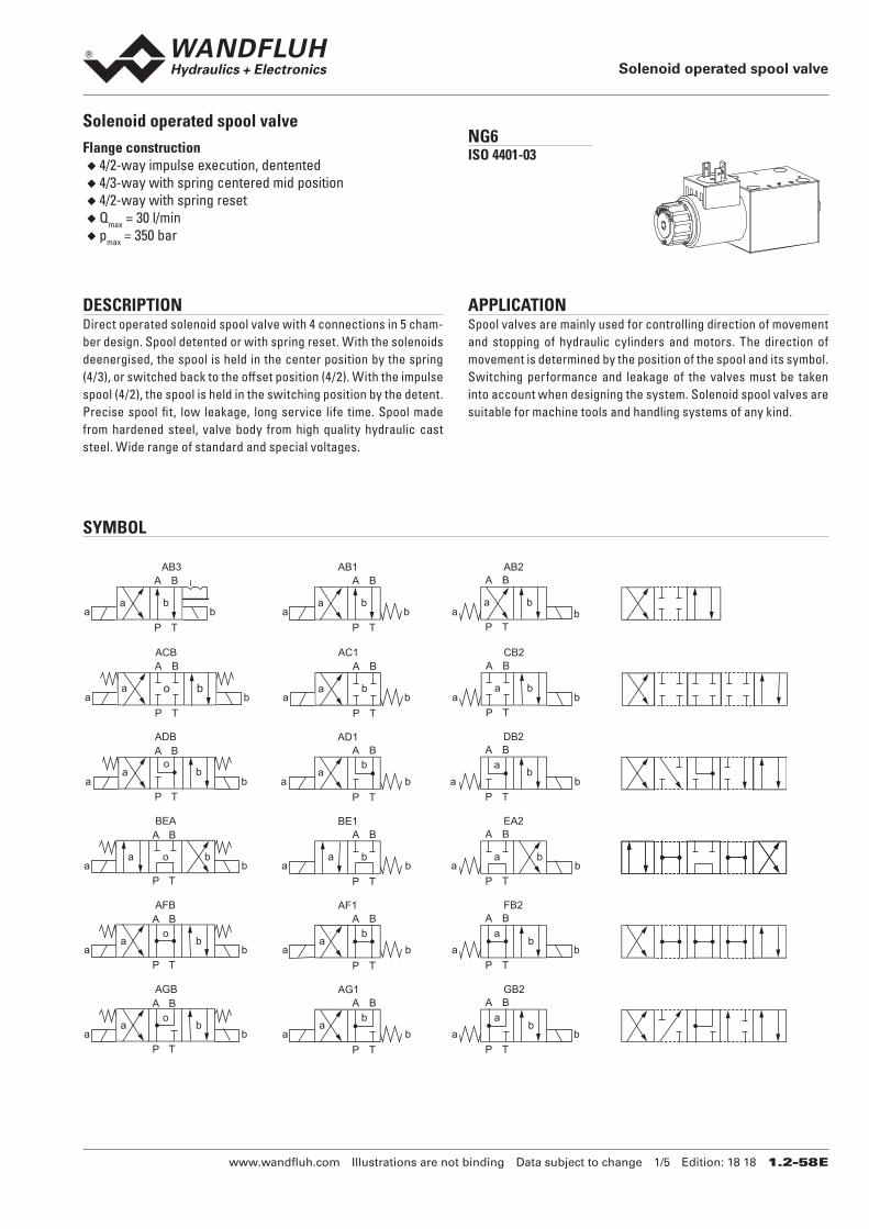
Solenoid operated spool valve
www.wandfluh.com Illustrations are not binding Data subject to change 1/5 Edition: 18 18 1.2-58 E
Solenoid operated spool valveFlange construction
◆ 4/2-way impulse execution, dentented ◆ 4/3-way with spring centered mid position ◆ 4/2-way with spring reset ◆ Qmax = 30 l/min ◆ pmax = 350 bar
NG6ISO 4401-03
DESCRIPTION Direct operated solenoid spool valve with 4 connections in 5 cham-ber design. Spool detented or with spring reset. With the solenoids deenergised, the spool is held in the center position by the spring (4/3), or switched back to the offset position (4/2). With the impulse spool (4/2), the spool is held in the switching position by the detent. Precise spool fit, low leakage, long service life time. Spool made from hardened steel, valve body from high quality hydraulic cast steel. Wide range of standard and special voltages.
APPLICATION Spool valves are mainly used for controlling direction of movement and stopping of hydraulic cylinders and motors. The direction of movement is determined by the position of the spool and its symbol. Switching performance and leakage of the valves must be taken into account when designing the system. Solenoid spool valves are suitable for machine tools and handling systems of any kind.
SYMBOL
a b
A B
P T
ba
A B
P Ta b
AB1 AB2
a b
A B
P Ta
AB3
b b a
a o
A B
P T
b a b
A B
P T
ba
A B
P Ta b a b
ACB AC1 CB2
b a
A B
P T
A B
P T
ba
A B
P Ta b a
ADB AD1 DB2
a bo
ab
b a b
A B
P T
A B
P T
ba
A B
P Ta b a
BEA BE1 EA2
a bo a bb a b
A B
P T
A B
P T
ba
A B
P Ta b a b
AFB AF1 FB2
a bo
ab
b a
A B
P T
A B
P T
ba
A B
P Ta b a b
AGB AG1 GB2
a bo
ab
b a
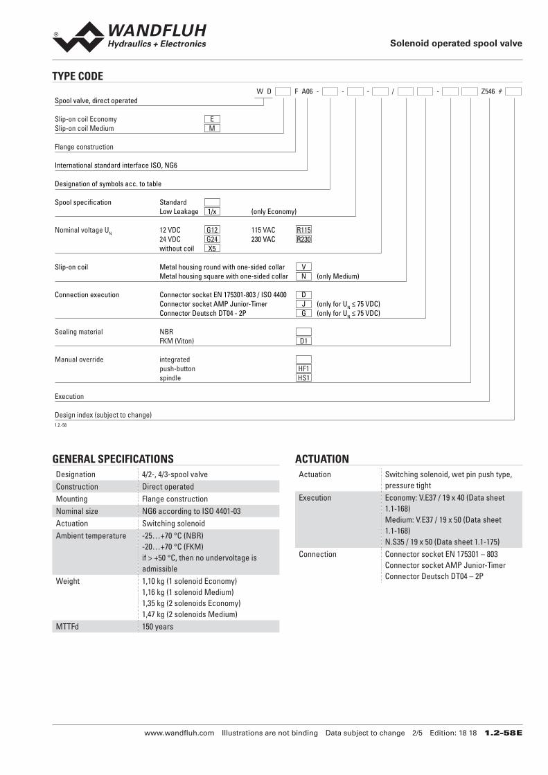
TYPE CODE
W D F A06 - - - / - Z546 # Spool valve, direct operated
Slip-on coil Economy ESlip-on coil Medium M
Flange construction
International standard interface ISO, NG6
Designation of symbols acc. to table
Spool specification Standard Low Leakage 1/x (only Economy)
Nominal voltage UN 12 VDC G12 115 VAC R115 24 VDC G24 230 VAC R230 without coil X5
Slip-on coil Metal housing round with one-sided collar V Metal housing square with one-sided collar N (only Medium)
Connection execution Connector socket EN 175301-803 / ISO 4400 D Connector socket AMP Junior-Timer J (only for UN ≤ 75 VDC) Connector Deutsch DT04 - 2P G (only for UN ≤ 75 VDC)
Sealing material NBR FKM (Viton) D1
Manual override integrated push-button HF1 spindle HS1
Execution
Design index (subject to change)1.2.-58
Solenoid operated spool valve
www.wandfluh.com Illustrations are not binding Data subject to change 2/5 Edition: 18 18 1.2-58 E
GENERAL SPECIFICATIONS
Designation 4/2-, 4/3-spool valveConstruction Direct operatedMounting Flange constructionNominal size NG6 according to ISO 4401-03Actuation Switching solenoidAmbient temperature -25…+70 °C (NBR)
-20…+70 °C (FKM)if > +50 °C, then no undervoltage is admissible
Weight 1,10 kg (1 solenoid Economy)1,16 kg (1 solenoid Medium)1,35 kg (2 solenoids Economy)1,47 kg (2 solenoids Medium)
MTTFd 150 years
ACTUATION
Actuation Switching solenoid, wet pin push type, pressure tight
Execution Economy: V.E37 / 19 x 40 (Data sheet 1.1-168)Medium: V.E37 / 19 x 50 (Data sheet 1.1-168)N.S35 / 19 x 50 (Data sheet 1.1-175)
Connection Connector socket EN 175301 – 803Connector socket AMP Junior-TimerConnector Deutsch DT04 – 2P
ELECTRICAL SPECIFICATIONS
Protection class Connection execution D: IP65Connection execution J: IP66Connection execution G: IP67 and IP69K
Relative duty factor 100 % DF Switching frequency 15'000 / hService life time 107 (number of switching cycles,
theoretically)Voltage tolerance ± 10 % with regard to nominal voltageStandard nominal voltage
12 VDC, 24VDC, 115 VAC, 230 VACAC = 50 to 60 Hz, rectifier integrated in the connector socket
Note! Other electrical specifications see data sheet 1.1-168 (slip-on coil V) and 1.1-175 (slip-on coil N)
Solenoid operated spool valve
www.wandfluh.com Illustrations are not binding Data subject to change 3/5 Edition: 18 18 1.2-58 E
HYDRAULIC SPECIFICATIONS
Working pressure pmax = 350 bar (PT < 20 bar)pmax = 315 bar (PT > 20 bar)
Tank pressure pTmax = 100 barMaximum volume flow Qmax = 30 l/min, see characteristicsLeakage oil See characteristicsFluid Mineral oil, other fluid on requestViscosity range 12 mm2/s…320 mm2/sTemperature range fluid
-20…+70 °C
Contamination efficiency
Class 20 / 18 / 14
Filtration Required filtration grade ß 10…16 ≥ 75, see data sheet 1.0-50
PERFORMANCE SPECIFICATIONS Oil viscosity u = 30 mm2/s
p = f (Q) Performance limitsMeasured with nominal voltage -10 %Economy
350300250200150100500
0 5 10 15 20 Q [l/min]
K1026
p [bar]
AB3/ACBADB/AGB
AB1
BEA
AFB
p = f (Q) Performance limitsMeasured with nominal voltage -10 %Medium
350300250200150100500
0 5 10 15 20 25 30 Q [l/min]
K1027
p [bar] ADB/BEA/AFB
AB1/AB3ACB/AGB
p = f (Q) Performance limitsMeasured with nominal voltage -10 %Low Leakage
350300250200150100500
0 2 4 6 8 10 Q [l/min]
K1028
p [bar] AB3
ADB
AB1
SEALING MATERIAL NBR or FKM (Viton) as standard, choice in the type code
SURFACE TREATMENT ◆ The valve body is painted with a two component paint ◆ The armature tube, the slip-on coil and the plug screw are zinc-nickel coated
QL = f (Q) Leakage volume flow characteristics per control edgeEconomy/Medium
4035302520151050
0 50 100 150 200 250 300 350 p [bar]
K1031
Q [cm3/min]
QL = f (Q) Leakage volume flow characteristics per control edgeLow Leakage
121086420
0 50 100 150 200 250 300 350 p [bar]
K1032
Q [cm3/min]
Solenoid operated spool valve
www.wandfluh.com Illustrations are not binding Data subject to change 4/5 Edition: 18 18 1.2-58 E
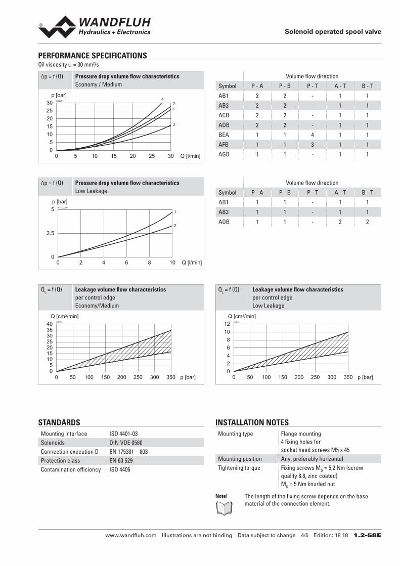
PERFORMANCE SPECIFICATIONS Oil viscosity u = 30 mm2/s
STANDARDS
Mounting interface ISO 4401-03Solenoids DIN VDE 0580Connection execution D EN 175301 – 803Protection class EN 60 529Contamination efficiency ISO 4406
INSTALLATION NOTES
Mounting type Flange mounting4 fixing holes forsocket head screws M5 x 45
Mounting position Any, preferably horizontalTightening torque Fixing screws MD = 5,2 Nm (screw
quality 8.8, zinc coated)MD = 5 Nm knurled nut
Note! The length of the fixing screw depends on the base material of the connection element.
Δp = f (Q) Pressure drop volume flow characteristicsEconomy / Medium
302520151050
0 5 10 15 20 25 30 Q [l/min]
K1029
p [bar]
12
3
4
Volume flow direction
Symbol P - A P - B P - T A - T B - T
AB1 2 2 - 1 1
AB3 2 2 - 1 1
ACB 2 2 - 1 1
ADB 2 2 - 1 1
BEA 1 1 4 1 1
AFB 1 1 3 1 1
AGB 1 1 - 1 1
Δp = f (Q) Pressure drop volume flow characteristicsLow Leakage
2
15
2.5
00 2 4 6 8 10 Q [l/min]
K1122_neu
p [bar]
Volume flow direction
Symbol P - A P - B P - T A - T B - T
AB1 1 1 - 1 1
AB3 1 1 - 1 1
ADB 1 1 - 2 2
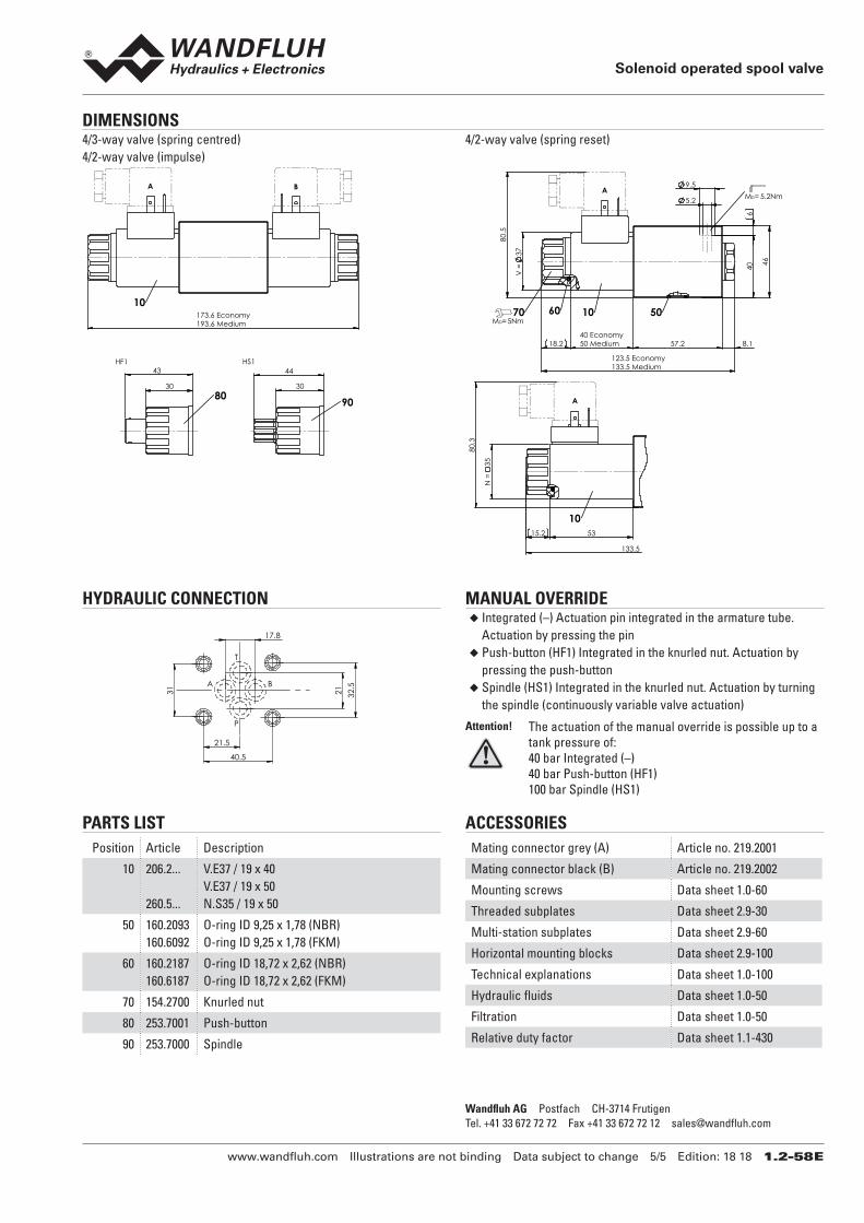
DIMENSIONS 4/3-way valve (spring centred)4/2-way valve (impulse)
173.6 Economy193.6 Medium
10
30
43 HF1
80 30
44 HS1
90
BA
4/2-way valve (spring reset)
18.2 8.1
46
V =
37
123.5 Economy133.5 Medium
40 Economy50 Medium 57.2
6
40
9.5
5.2
80.
5
A
MD=5Nm
MD= 5.2Nm
70 60 10 50
53 15.2
133.5
N =
35 8
0.3
10
A
Solenoid operated spool valve
www.wandfluh.com Illustrations are not binding Data subject to change 5/5 Edition: 18 18 1.2-58 E
HYDRAULIC CONNECTION
17.8
21
32.
5
31
40.5
21.5
B
T
P
A
MANUAL OVERRIDE ◆ Integrated (–) Actuation pin integrated in the armature tube. Actuation by pressing the pin ◆ Push-button (HF1) Integrated in the knurled nut. Actuation by pressing the push-button ◆ Spindle (HS1) Integrated in the knurled nut. Actuation by turning the spindle (continuously variable valve actuation)
Attention! The actuation of the manual override is possible up to a tank pressure of: 40 bar Integrated (–)40 bar Push-button (HF1)100 bar Spindle (HS1)
PARTS LIST
Position Article Description
10 206.2...
260.5...
V.E37 / 19 x 40V.E37 / 19 x 50N.S35 / 19 x 50
50 160.2093160.6092
O-ring ID 9,25 x 1,78 (NBR)O-ring ID 9,25 x 1,78 (FKM)
60 160.2187160.6187
O-ring ID 18,72 x 2,62 (NBR)O-ring ID 18,72 x 2,62 (FKM)
70 154.2700 Knurled nut
80 253.7001 Push-button
90 253.7000 Spindle
ACCESSORIES
Mating connector grey (A) Article no. 219.2001
Mating connector black (B) Article no. 219.2002
Mounting screws Data sheet 1.0-60
Threaded subplates Data sheet 2.9-30
Multi-station subplates Data sheet 2.9-60
Horizontal mounting blocks Data sheet 2.9-100
Technical explanations Data sheet 1.0-100
Hydraulic fluids Data sheet 1.0-50
Filtration Data sheet 1.0-50
Relative duty factor Data sheet 1.1-430
Wandfluh AG Postfach CH-3714 FrutigenTel. +41 33 672 72 72 Fax +41 33 672 72 12 [email protected]