Embed Size (px)
Citation preview

TS08H - 3D Principles and Technology, 6089 Mattia De Agostino, Andrea Lingua and Marco Piras SOLDEO: A New Solution for 3D GIS Data Recording FIG Working Week 2012 Knowing to manage the territory, protect the environment, evaluate the cultural heritage Rome, Italy, 6-10 May 2012
1/1
SOLDEO: a New Solution for 3D GIS Data Recording
Mattia DE AGOSTINO, Andrea LINGUA, Marco PIRAS, Ita ly Key words: Solid image, low cost, GNSS, INS SUMMARY The 3D data recording for 3D GIS is one of the main aims of scientific researchers and those who manage the environment and territory. Terrestrial LiDAR and photogrammetric techniques are effective methods of acquiring environmental data and of integrating their in digital products (i.e. solid images and solid true orthophotos). These techniques have shown remarkable effectiveness in many case studies or when the area of interest is limited. This integration is powerful, but it is not available for large area because a lot of time for the acquisition is required. A possible solution is to use a mobile system where LiDAR, GPS and camera sensors are contained. Different commercial solutions are available, but the cost (>300k€), the requirement of high skill and the low flexibility of the system reduce the number of potential application fields. The Geomatic group of the Politecnico di Torino has realized a mobile metallic platform that can be installed on any vehicle, where several sensors could be installed (i.e. GPS antenna, webcams, IMU, etc.). In this paper, the authors explain their attempts to use a mobile vehicle that was instrumented only with low cost sensors (i.e. LiDAR, GPS receivers and webcams) in order to have extensive use the LiDAR-photogrammetric integrated techniques for 3D data recording.. This kind of system requires dedicated procedures, in particular devoted to calibrating the system (absolute reference system), to elaborate the raw data with dedicated algorithms. A novel produce was realized to be able to make a deeper analysis: the SOLid viDEO (SOLDEO). The SOLDEO was born from the solid image experience (i.e. solid image), but in this case a continuous sequences of images were three-dimensional spatial information are contained and some measurements (points, lines, distances, angles,..) with coding can be done. The used procedures and the significant results obtained during the conducted survey campaign, are described, focusing the attention to the practical aspects.

TS08H - 3D Principles and Technology, 6089 Mattia De Agostino, Andrea Lingua and Marco Piras SOLDEO: A New Solution for 3D GIS Data Recording FIG Working Week 2012 Knowing to manage the territory, protect the environment, evaluate the cultural heritage Rome, Italy, 6-10 May 2012
2/2
SOLDEO: a New Solution for 3D GIS Data Recording
Mattia DE AGOSTINO, Andrea LINGUA, Marco PIRAS, Ita ly 1. INTRODUCTION The modern Geographic Information System (GIS) uses a large volume of spatial data, then the automation of data acquisition is very important in order to optimize the time and resource. This is especially true when map digitizing is insufficient and it is necessary to include other data or updating the existing ones. Several data can be acquired using aerial photogrammetry (building, roadside and so on), but there are various kind of data that can be recorded only with terrestrial techniques as street number, road signs, hydraulic infrastructure and so on. A possible solution can be use specific handled GPS/GNSS receivers proposed by some manufacturers devoted to GIS data collection using only a one device (e.g. GeoExplorer (Trimble), CS25 and Zeno (Leica Geosystems), T-GIS and GRS1 (Topcon), …). These tools are effective and economical when are uased in small extention, but where the extension of the survey area is large, they have problems due to long survey time and high operative costs. In application of medium and large extention, the use of the Land Based Mobile Mapping System (LBMMS, in this paper MMS) has led to a significant change in acquisition data activities (Swartz and El Sheimy, 2004) . These systems have recently had remarkable developments (Toth, 2009) and, nowadays, they help us to collect a large volume of data which derive by modern sensors like digital cameras and video-cameras, Inertial Measurement Units (IMUs), laser scanners and Global Navigation Satellite System (GNSS) receivers. Each sensor is able to collect data (i.e. image, position, point clouds) on a computer systems with a time tag (usually GPS time) required for data time synchronization. Fueled by an unprecedentedly strong request of high-resolution and accuracy of 3D geospatial data, these systems serve the probably fastest growing market segment: city modeling, road cadastre and so on. In particular, the recent introduction of powerful mobile laser-scanning systems is of main interest, as the direct acquisition of 3D data greatly simplifies the downstream processing, where until now stereo-based extraction was the most widely used feature extraction tool, requiring significantly more complex processing compared to the straightforward processing of explicit LiDAR data (Toth, 2009). The software architecture for the acquisition is rather straightforward, as the main task is to record the sensor measurements and properly time-tag them, so the data can be accurately georeferenced based on the GNSS/IMU-based navigation solution. The post-processing software of mobile LiDAR systems (Toth, 2009), however, is still rapidly evolving as better co-registration and feature extraction methods are introduced. The main challenge here is to separate the static and dynamic components of the object space (Markiel et al., 2008). This is an an exceptional task even for static sensor platform, but it becomes truly a difficult work if a mobile platform is considered. Having redundant points clouds, acquired with a fast rate, is definitely a necessary condition if a good performance in a robust solution is needed. For example, the identification of other vehicles, both moving and still, around a mobile LiDAR system and their removal is essential for topographic mapping. Several research have been done about the automatic extraction of road vector (Cheng et al, 2008), lane parameters (Roncella and Forlani, 2006), road boundaries (Bassani et al., 2011), but only few software tools have been developed for the complete end use of the acquired data that is usually the manual recording of the information necessary to modern GIS: in this case, the commercial solutions are very expensive (several K€/license), the use is complex (to be used only by expert users requiring specific tutorial, training and so on), strongly tied to the platform (one software for each MMS maker) and require PC with high-performance to run well in operational-functional way. To bridge this gap with final users and make it more usable data acquired by MMS spreading this technology, the authors propose a novel and innovative solution to manage these data in a cheap way using an easier and complete tool useful from unskilled users, platform-independent (usable with all the MMSs), with low hardware requirements to run.

TS08H - 3D Principles and Technology, 6089 Mattia De Agostino, Andrea Lingua and Marco Piras SOLDEO: A New Solution for 3D GIS Data Recording FIG Working Week 2012 Knowing to manage the territory, protect the environment, evaluate the cultural heritage Rome, Italy, 6-10 May 2012
3/3
The aim of this research is to create a collection of solid images, called SOLid viDEO (SOLDEO), where the user can see the whole of the acquired data and, where there is a point or a part of interest, can query the reality to collect data, measure objects and so on. Starting from the past experiences of the Geomatics group of the Politecnico di Torino about GIS and data acquisition fields, this research will be focused on the possibility to realize this solution using the data acquired by a low cost mobile mapping. 2. The SOLID IMAGE: a brief description As described in (Bornaz and Dequal, 2003), any image can, with a good approximation, be considered a central prospective of the photographed object. If the internal orientation parameters of the digital camera (position of perspective center in image coordinate system ξ,η) are known, it is possible to establish a direction (α, θ) in object coordinate system (x, y, z) for each pixel I of the image (see Figure 1a) measuring its image coordinates (ξΙ,ηΙ):
� � ������ ��� � � ��
������� (1)
where c is the principal distance of photographic camera that generates the image. One image is not sufficient to determine the 3D position of an object point. If a single image is used it is possible, at the most, to establish its direction in the space. In order to reconstruct objects in three dimensions, it is necessary to use at least 2 images according to the classical principles of photogrammetry. A valid alternative to the well-known photogrammetric plotting techniques is offered by the knowledge of the distance d between the center of perspective of an image and the object itself for each direction in the space (Figure 1b). In this way it is possible to establish the position of any object point O in the (x, y, z) coordinate system, using simple geometric equations:
� � �� �������� � ������� � ��� ��� �� (2)
where ϑ,α are determined as previously shown (1).
Figure 1 Definition of Solid Image The coordinates (xo, yo, zo) can be transformed in mapping coordinate system (X, Y, Z) by means of a simple 3D roto-translation that can be defined using the navigation data (point of view position and attitude). The structure of solid image (SI) is composed as following: the traditional RGB color data (and other radiometric bands) of the image is completed with a supplementary “range matrix” that has the same size as the RGB matrices, in terms of pixel size, number of rows and columns and contains distance data for each pixel.

TS08H - 3D Principles and Technology, 6089 Mattia De Agostino, Andrea Lingua and Marco Piras SOLDEO: A New Solution for 3D GIS Data Recording FIG Working Week 2012 Knowing to manage the territory, protect the environment, evaluate the cultural heritage Rome, Italy, 6-10 May 2012
4/4
Figure 2 The structure of Solid Image
In order to determine the previously defined distances for each pixel of the digital image, a dense digital surface model (DDSM) can be used. These 3D models are today easily obtained by laser scanners or LiDAR MMSs in form of point cloud. At first, it is necessary to define the characteristics of a used digital camera: focal length, pixel size, number of rows and columns, internal orientation parameters, lens distortions and sensor calibration using Brown model (McGlone et al.,2004), . Then, the external orientation (EO) parameters of the image can be calculated using the navigation solution (GNSS/IMU). The third step consists in projecting each point of LiDAR point cloud onto the SI. This operation consists in calculating, for each LiDAR point, the corresponding image coordinates ξ, η using collinearity equation:
( ) ( ) ( )( ) ( ) ( )033023013
0310210110 ZZrYYrXXr
ZZrYYrXXrc
−+−+−−+−+−−∆+= ξξξ (3)
( ) ( ) ( )( ) ( ) ( )033023013
0320220120 ZZrYYrXXr
ZZrYYrXXrc
−+−+−−+−+−−∆+= ηηη
where: (X0, Y0, Z0) are the mapping coordinates of projection center (GNSS); (X,Y,Z) are the mapping coordinates of a STOP pixel; rij are the 9 element of a 3x3 rotation matrix defined by (ω, φ, κ) (IMU); c is the focal length; (ξ,η) are the (solid) image coordinate of a projected STOP pixel; (ξ0,η0) are the (solid) image coordinate of the principal point; (∆ξ,∆η) are the lens and sensor distortions using Brown model. The distance between the LiDAR point and projection center can be calculate by:
� � ��� � ���� � �� � ���� � �� � ���� (4) The relative pixel of SI is defined using (ξ,η) and the SI pixel size, than the original data (RGB, d and other radiometric data) can be write into the SI matrixes in this correspondent position. The density of the pixels in the digital image is usually much higher than the density of the original data . For this reason, when the point cloud is projected onto the digital image, the SI matrixes is not completely filled: the distance and the RGB values are only associated to some pixels (this quantity depends on the density of the original data and on the image resolution in terms of dpi). In order to fill these gaps, it is necessary to integrate

TS08H - 3D Principles and Technology, 6089 Mattia De Agostino, Andrea Lingua and Marco Piras SOLDEO: A New Solution for 3D GIS Data Recording FIG Working Week 2012 Knowing to manage the territory, protect the environment, evaluate the cultural heritage Rome, Italy, 6-10 May 2012
5/5
the missing values with an interpolation process. The “inverse distance weighed method” has been used. The four nearest pixels, of which the value (distance or RGB values is known, are considered. If the surveyor uses an additional digital camera, the SI generation is easier.
3. SOLID VIDEO: the main concept Starting from this principle of SI, the solid video is simply derived. MMSs can acquire sequence of digital images devoted to show and describe the road path and its neighbors. The use of this images to extract useful information requires photogrammetric procedures and therefore various and more complex software tools. Using low cost MMS (Bassani et al, 2012), the photogrammetric way is more difficult due to the accuracy of navigation solutions and, consequently, of image EO parameters. The LiDAR instruments permit to solve this problem in a different and more simple way. The idea is to transform each digital image in a solid image with:
- an integer index (image ID) to identify an image into the sequence; - EO parameters derived by GNSS/IMU solution; - a range image generated by LiDAR data.
The result is a sequence of SIs when each SI can be used, as described in §2. The solid video (SV), in fact, is fundamentally a series of solid images collected like a video. The structure of SV is shown in Figure 3. In MMS application, the range image can be recorded using a variable integer of 2 bytes that permits to collect distances until 327.68 m, assuming a numerical precision of 1 cm.
Figure 3 The structure of SV

TS08H - 3D Principles and Technology, 6089 Mattia De Agostino, Andrea Lingua and Marco Piras SOLDEO: A New Solution for 3D GIS Data Recording FIG Working Week 2012 Knowing to manage the territory, protect the environment, evaluate the cultural heritage Rome, Italy, 6-10 May 2012
6/6
3.1 The generation of SV The generation of SV is based on the procedure of SI production (§2), but in MMS application, some particular attentions are required First, the large amount of data acquired by LiDAR doesn’t permit the use of the entire point cloud for the generation of all the SIs (as described in 2) that could require a processing of very long time. An effective optimization can be obtained selecting a little set of points from the entire point cloud using a selection box defined by (see Figure 4):
- size along the vehicle direction about 50-100 m (parameterized); - size across the vehicle direction 30-60 m (parameterized); - any value of size in height direction; - the direction of maximum size of box is along the vehicle direction with correct versus; - the horizontal limit of box is located in correspondence of the image point of view.
In this way, the generation of each SI uses an average number of points of 50-100000, in function of the kind of path (urban or extra-urban), the vehicle velocity and the LiDAR scan density: the processing can be done using a specific software developed by the authors in Intel Visual Fortran. A solid image of 1024x768 px requires few seconds (5-15 s) for the processing, with respect the PC performance and if the interpolation of range image is necessary. Assuming a speed equalt to 10 m/s and a frame rate equal to 7 fps with a single camera, the production of SIs relative to 1 km of surveyed road requires about 10-30 hours using a batch procedure, where human intervention is not requested.
Figure 4 The generation of SV
The memory occupation could be optimized if the final result is a sequence of solid images when: - each digital image is saved in JPEG format (about 10 kb/image); - each range image is recorded GEOTIFF using a lossless (LZW) compression algorithm (about 140
kb/image).

TS08H - 3D Principles and Technology, 6089 Mattia De Agostino, Andrea Lingua and Marco Piras SOLDEO: A New Solution for 3D GIS Data Recording FIG Working Week 2012 Knowing to manage the territory, protect the environment, evaluate the cultural heritage Rome, Italy, 6-10 May 2012
7/7
A correct, complete and 3D representation of 1 km of road requires about 105 Mb of memory. 3.2 The Solid video viewer A Solid Video can be shown using a dedicated software tools implemented by the authors in Intel Visual Fortran with GINO 7.5 graphic library. The SV viewer is derived by a previous solution developed for a super low cost MMS proposed by the authors in (Bendea et al.,2011). The purpose is to offer to users an easier product to manage and consult because they can see in few minutes several numbers of solid images, stopping the sequences where a detail or a point of interest is seen. Figure 5a shows the commands to select a camera (it is possible to use up to 4 simultaneous cameras), to play in direct and reverse versus and to define the reproduction speed. Like a movie, when the video is stopped, it is possible to use that frame to make different kind of observations First, the single SI can be see with 3 graphic windows at different level of zoom (named scroll, image and zoom) (Figure 5c) and, moving the cursor inside they, it is possible to read the 3D cartographic coordinates (Figure 5b). Second, the user can query the single SI (Figure 5d) to acquire some measurements as 3D distances and angles or to collect geometrical elements as points and polylines. Third, an ID number and a code (layer) can be associate to all the collected elements for easier data entry in a GIS structure (Figure 5e): the collected data can be exported in ASCII file and DXF (Data eXchange Format).
Figure 5. The SV viewer
4 Case Study In order to evaluate the effective capability of the SV approach using data derived from low cost system, a dedicated test has been realized, where a low cost mobile mapping has been involved. In the following parts, the mobile mapping, the test and the first results will be described.

TS08H - 3D Principles and Technology, 6089 Mattia De Agostino, Andrea Lingua and Marco Piras SOLDEO: A New Solution for 3D GIS Data Recording FIG Working Week 2012 Knowing to manage the territory, protect the environment, evaluate the cultural heritage Rome, Italy, 6-10 May 2012
8/8
4.1 Description of the acquisition system With the MMS concept as a starting point, in 2007 the Geomatics Research Group of the Politecnico di Torino designed and built a MMS. This system consisted of a metallic bar which is compatible for use with any vehicle which can hold up to four GNSS antennas, three inertial sensors (Crossbow IMU 700CA, Crossbow IMU 400CC and XSens MTi), three web-cameras (Logitech Quickcam Pro 9000, with a resolution of up to 2 megapixels) and a terrestrial laser scanner (Sick LMS100). With the aim of developing a new MMS to be used specifically in the field of alignment detection, the authors worked together in 2010 on the development of a new apparatus (Figure 6). It is basically composed of one integrated platform GPS/IMU (XSens MTi-G, Table 1) and a webcam (Logitech Quickcam Pro 9000). The new MMS prototype presented has been fitted out with low cost sensors which have a medium level of accuracy. In this investigation, three other geodetic GNSS receivers Leica GX1230+GNSS have been mounted on the same bar. These last mentioned sensors are most likely redundant but they have been used in order to verify and assess the quality of the new system. This MMS required some “homemade” modifications prior to use. In particular, a dedicated data acquisition software program and a calibration procedure were developed in order to obtain geo-referenced data.
Specification – IMU Angular Rate Range Roll, Pitch, Yaw (°/s) ± 300 Bias: Roll, Pitch (°/s) ± 0.5 Bias: Yaw (°/s) ± 1.0 Resolution (°) 0.05 Acceleration Range X/Y/Z, m/s2 (ft/sec2) ± 50 (± 164.04) Bias: X/Y/Z, m/s2 (ft/sec2) ± 0.02 (± 0.06) Resolution, m/s2 (ft/sec2) 0.0098 (± 0.0322) Update Rate, Hz 512 Specification – GPS Raw Measurements L1 frequency, C/A code No. Channels 50 Max. update rate, Hz 4 Operating temperature, °C (°F) –40 to 85 (-40 to 185)
Table 1. XSens MTi-G Specification
Figure 6. The new low cost prototype MMS with sensors: (1) GNSS receivers Leica GX1230+, (2) GPS/IMU XSens MTi-G, (3) Logitech Quickcam Pro 9000 webcam, (4) LMS-110 Sick laser scanner 4.2 Calibration of the system The calibration of optical lenses, the definition of 3D transformation between coordinate systems of various sensors, the synchronization of time devices and the integration between sensors have been considered and estimated in order to derive data useful for geometrical analysis.
1 1
1
2 4
3

TS08H - 3D Principles and Technology, 6089 Mattia De Agostino, Andrea Lingua and Marco Piras SOLDEO: A New Solution for 3D GIS Data Recording FIG Working Week 2012 Knowing to manage the territory, protect the environment, evaluate the cultural heritage Rome, Italy, 6-10 May 2012
9/9
As is common knowledge, every optical lens suffers from radial and tangential distortions that must be eliminated. In this case, a dedicated calibration field has been realized, with several photos taken from different vantage points and angulations. The acquired images have been processed with iWitness, which is a software program dedicated to the estimation of lens distortions using the auto-calibration algorithm through a selection of homologous points (Figure 7).
(a) (b) Figure 7. Screenshot of the iWitness software used for lens calibration (a) and calibration field (b) Each sensor on the MMS has a local reference system. The relationships (three shifts, three rotations and one scale factor) between each local system and the mapping reference system (East, North, Height) are the fundamental elements required to assign, in the final stage, the absolute coordinates to each pixel of the image. Using a calibration field and a total station, the positions of several targets have been estimated in each local reference system with respect to the absolute reference system (UTM projection). 4.3 In field acquisition Time synchronization is a key aspect of every MMS as it permits the coordination of all the collected data. It is necessary to have one common time because each sensor has its own internal clock, with its own drift, accuracy and stability. Any discrepancies would result in data (images, positions, attitudes) not being synchronized. The GPS time was taken as a reference. For this purpose the software GEOWASP was used. The software has been developed by the authors and the non-profit association Information Technology for Humanitarian Assistance, Cooperation and Action (ITHACA) in the C# language and dedicated Windows API routines have been included. The package is composed of two modules. The first one is dedicated to the synchronization between PC-time and GPS-time. At the same time, GPS time and PC time are written to a text file. It is also possible to include the instantaneous coordinate and the time of recording of a particular point of interest. The second GEOWASP module acquires the images and allows the management of up to six webcams in simultaneous operation. The webcam configuration (zoom, resolution, light conditions, etc.) could be changed using the webcam’s own software (Logitech Webcam Software). In this case the resolutions used were equal to 960x720 pixels, with the number of frames per second being 8-10. The IMU data were collected using a sample rate of 50Hz, by software developed by XSens called MT Manager. The data are stored in a proprietary format (.mtb) and can be easily converted into an ASCII file using a dedicated tool. The MTi-G sensor directly gives a loosely coupled solution (GPS/IMU solution), which is composed of three-dimensional positions (latitude, longitude and ellipsoidal height), accelerations and velocities along the three main axes (X,Y,Z) and the related accuracies. These solutions are stored in a text file but, unfortunately, the raw data (IMU and GPS) are not stored since the coupled GPS/IMU data is not available in post-processing. Figure 8 shows the highway segment which was selected as the case study on which to test the proposed MMS. The segment (about 6 km) comprises two roundabouts (E & W) located along the National Route n.23 that links Turin to Sestriere (Italy), two of the main competition sites for the 2006 Winter Olympic Games. The data have

TS08H - 3D Principles and Technology, 6089 Mattia De Agostino, Andrea Lingua and Marco Piras SOLDEO: A New Solution for 3D GIS Data Recording FIG Working Week 2012 Knowing to manage the territory, protect the environment, evaluate the cultural heritage Rome, Italy, 6-10 May 2012
10/10
been acquired in both directions.
Figure 8. Aerial photograph of the case study highway segment along the Italian National Route n.23 (picture from Google Earth™)
4.4 First results The navigation solution (position and attitude) of the vehicle have been directly estimated by X-sens sensors. Using 3D transformation of Sick defined during the calibration of system, it was possible to calculate the mapping coordinates of LiDAR points. The obtained point cloud (about 2 million of points) is shown in Figure 9 using Mesh Lab, an open source software for visualization and processing of LiDAR data. The EO parameters of acquired images (about 11000 images) have been estimated using the navigation solution and the synchronization data provided by GEOWASP: these data have been used to generate SV in about 120 hours (batch procedure) correspondent to about 5 days. An example of the SV generated has shown in Figure 5. Using SV, the data required to describe this road have been collected and inserted in a GIS environment.
Figure 9. The acquired point cloud (a) and a detail near the roundabout
TS08H - 3D Principles and Technology, 6089 Mattia De Agostino, Andrea Lingua and Marco Piras SOLDEO: A New Solution for 3D GIS Data Recording FIG Working Week 2012 Knowing to manage the territory, protect the environment, evaluate the cultural heritage Rome, Italy, 6-10 May 2012
11/11
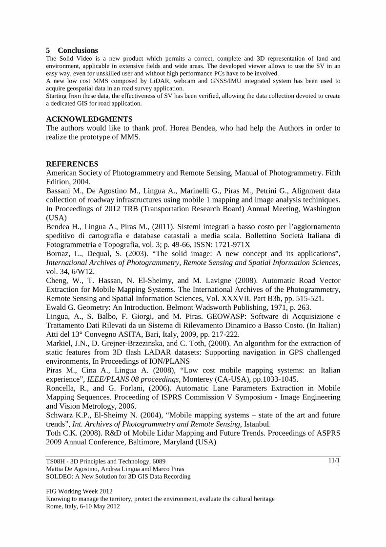
5 Conclusions The Solid Video is a new product which permits a correct, complete and 3D representation of land and environment, applicable in extensive fields and wide areas. The developed viewer allows to use the SV in an easy way, even for unskilled user and without high performance PCs have to be involved. A new low cost MMS composed by LiDAR, webcam and GNSS/IMU integrated system has been used to acquire geospatial data in an road survey application. Starting from these data, the effectiveness of SV has been verified, allowing the data collection devoted to create a dedicated GIS for road application. ACKNOWLEDGMENTS The authors would like to thank prof. Horea Bendea, who had help the Authors in order to realize the prototype of MMS. REFERENCES American Society of Photogrammetry and Remote Sensing, Manual of Photogrammetry. Fifth Edition, 2004. Bassani M., De Agostino M., Lingua A., Marinelli G., Piras M., Petrini G., Alignment data collection of roadway infrastructures using mobile 1 mapping and image analysis techiniques. In Proceedings of 2012 TRB (Transportation Research Board) Annual Meeting, Washington (USA) Bendea H., Lingua A., Piras M., (2011). Sistemi integrati a basso costo per l’aggiornamento speditivo di cartografia e database catastali a media scala. Bollettino Società Italiana di Fotogrammetria e Topografia, vol. 3; p. 49-66, ISSN: 1721-971X Bornaz, L., Dequal, S. (2003). “The solid image: A new concept and its applications”, International Archives of Photogrammetry, Remote Sensing and Spatial Information Sciences, vol. 34, 6/W12. Cheng, W., T. Hassan, N. El-Sheimy, and M. Lavigne (2008). Automatic Road Vector Extraction for Mobile Mapping Systems. The International Archives of the Photogrammetry, Remote Sensing and Spatial Information Sciences, Vol. XXXVII. Part B3b, pp. 515-521. Ewald G. Geometry: An Introduction. Belmont Wadsworth Publishing, 1971, p. 263. Lingua, A., S. Balbo, F. Giorgi, and M. Piras. GEOWASP: Software di Acquisizione e Trattamento Dati Rilevati da un Sistema di Rilevamento Dinamico a Basso Costo. (In Italian) Atti del 13° Convegno ASITA, Bari, Italy, 2009, pp. 217-222. Markiel, J.N., D. Grejner-Brzezinska, and C. Toth, (2008). An algorithm for the extraction of static features from 3D flash LADAR datasets: Supporting navigation in GPS challenged environments, In Proceedings of ION/PLANS Piras M., Cina A., Lingua A. (2008), “Low cost mobile mapping systems: an Italian experience”, IEEE/PLANS 08 proceedings, Monterey (CA-USA), pp.1033-1045. Roncella, R., and G. Forlani, (2006). Automatic Lane Parameters Extraction in Mobile Mapping Sequences. Proceeding of ISPRS Commission V Symposium - Image Engineering and Vision Metrology, 2006. Schwarz K.P., El-Sheimy N. (2004), “Mobile mapping systems – state of the art and future trends”, Int. Archives of Photogrammetry and Remote Sensing, Istanbul. Toth C.K. (2008). R&D of Mobile Lidar Mapping and Future Trends. Proceedings of ASPRS 2009 Annual Conference, Baltimore, Maryland (USA)

TS08H - 3D Principles and Technology, 6089 Mattia De Agostino, Andrea Lingua and Marco Piras SOLDEO: A New Solution for 3D GIS Data Recording FIG Working Week 2012 Knowing to manage the territory, protect the environment, evaluate the cultural heritage Rome, Italy, 6-10 May 2012
12/12
BIOGRAPHICAL NOTES The research group has long been realized and developed the concept of a solid image, particularly for environmental applications (survey of geomechanical rock walls) or architectural (building facades). This type of product you are trying to accomplish with moving systems, such as mobile mapping. For several years the authors work on the topic of low-cost mobile mapping. especially in 2008 were involved in the testing of road cadastre of the Piedmont Region. For this occasion they have developed the first prototype of low-cost mobile mapping, conceived as a calibrated metal rod can be installed on different vehicles. The research on mobile mapping was carried out considering both the integration of sensors (INS, GNSS) and six individual behaviors low cost sensors used. These studies have led to several publications, both national and international arena, where some of them were presented as contributions to international conferences (e.g. PLANS, ION). CONTACTS Prof. P.E. Andrea Lingua Politecnico di Torino - DIATI c.so Duca degli Abruzzi 24 Torino Italy Tel. +390110907700 Fax + 390110907699 Email: [email protected] Web site: www.polito.it Ph.D. Eng. P.E. Mattia De Agostino Politecnico di Torino - DIATI c.so Duca degli Abruzzi 24 Torino Italy Email: [email protected] Web site: www.polito.it Ph.D. Eng. P.E. Marco Piras Politecnico di Torino - DIATI c.so Duca degli Abruzzi 24 Torino Italy Tel. +390110907661 Fax + 390110907699 Email: [email protected] Web site: www.polito.it

TS08H - 3D Principles and Technology, 6089 Mattia De Agostino, Andrea Lingua and Marco Piras SOLDEO: A New Solution for 3D GIS Data Recording FIG Working Week 2012 Knowing to manage the territory, protect the environment, evaluate the cultural heritage Rome, Italy, 6-10 May 2012
13/13