Embed Size (px)
Citation preview
OPERATOR'S MANUAL
PUBLICATION DATE: 4/11/05, Rev. 4 MILLCREEK PART # 43807
MILLCREEK MODEL:SPIN GROOMER with
OPTIONAL RAKE ATTACHMENT(sold separately)
WARNING: DO NOT assemble, operate, or maintain this equipment without first reading and understanding the information provided in this manual. Failure to follow all safety precautions as stated in the manual may result in serious
personal injury or death.
Millcreek Manufacturing Company34 Zimmerman Road
Leola, PA 17540Phone: 1-800-311-1323 / Fax: 717-656-0952
www.millcreekspreaders.com

WARRANTY INFORMATION
TRADEMARKSThe Millcreek logo is a trademark of the Millcreek Manufacturing Company. All other brand or product namesmentioned are the registered trademarks or trademarks of their respective owners.
COPYRIGHTCopyright © 2005 Millcreek Manufacturing Company. All rights reserved. No part of this publication may bereproduced, or distributed without the prior written permission of Millcreek Manufacturing Company, 34 ZimmermanRoad, Leola, PA 17540. Subject to change without notice.
Millcreek Manufacturing Company (hereinafter called the Company) warrants to the original Purchaser, theEquipment, manufactured by the Company, to be free from defects in material and workmanship under normaluse and service. The Company obligation under this Warranty shall be limited to replacement or repair of anyparts thereof, free of charge, to the original Purchaser, at their place of business, provided, however, that thepart(s) to be replaced or repaired, shall, within one year after delivery to the original Purchaser, be demonstratedto be defective; which determination shall be made by the Company. The said components or parts must bereturned through the Selling Dealer or Distributor directly to the Company with all transportation charges prepaid.Notice of defect shall be furnished in writing to the Seller and to the agent through whom the machinery waspurchased, disclosing in full all known defects and failure in operation and use. Reasonable time shall be given tothe Seller to remedy any such defects and failures.
This Warranty does not cover, under any circumstances, any parts, components, or materials which, in the opinionof the Seller and the Company, have been subjected to neglect, misuse, alteration, accident, or repaired with partsother than those manufactured by and obtained from Millcreek Manufacturing Company.
This Warranty does not cover components which are already covered by a separate warranty provided by thesupplier of said parts or components.
This Warranty is made in lieu of all other warranties, expressed or implied, including any warranty ofmerchantability and fitness for use and purpose and of all other obligations or liabilities on the Companypart and any implied warranty. The Company neither assumes nor authorizes any other person to assumefor it, any other liability in connection with the sale of this equipment. This Warranty shall not apply tothis equipment or to any part thereof which has been subjected to accident, negligence, alteration, abuse,or misuse.
The Company makes no warranty whatsoever in respect to accessories or parts not supplied by the Company.The term "original Purchaser," as used in this Warranty, shall be deemed to mean that person for whom theequipment is originally supplied. This Warranty shall apply only within the boundaries of the continental UnitedStates.
Under this Warranty, the Company cannot guarantee that conditions existing beyond its control will not affect theCompany's ability to obtain materials or manufacture necessary replacement parts.
The Company reserves the right to make design changes, or changes in specifications at any time, without anycontingent obligation on the part of the Company to purchasers of machines and parts previously sold.
The Company warrants the construction of the equipment sold herein and will replace at the Company's expensefor a period of one year from the date hereof, any parts which prove defective as determined under the terms ofthis Limited Warranty.

TABLE OF CONTENTS
SECTION 1: INTRODUCTION.................................................................................... 1-1Guide to this Manual ........................................................................................................ 1-1For Your Safety... ............................................................................................................. 1-1
Safety Labels ............................................................................................................. 1-3
SECTION 2: UNPACKING & ASSEMBLY ................................................................. 2-1Removing the Shipping Crate .......................................................................................... 2-1Warranty Registration ...................................................................................................... 2-1Attaching the 3-Point Mast to the Spin Groomer Hitch ................................................... 2-2Assembling the Spin Groomer Hitch to the Grooming Ring ........................................... 2-2Assembling the Rake........................................................................................................ 2-3Attaching the Rake to the Spin Groomer ......................................................................... 2-4Connecting the Spin Groomer Hitch to the Tractor ......................................................... 2-5Connecting the Rake Attachment to the Tractor .............................................................. 2-5
SECTION 3: OPERATION .......................................................................................... 3-1Understanding Spin Groomer and Rake Attachment Operation ...................................... 3-1
How the Spin Groomer Works .................................................................................. 3-1How the Rake Attachment Works ............................................................................. 3-1
Operating the Spin Groomer ............................................................................................ 3-2Adjusting the Spin Groomer for Operation ............................................................... 3-2Operating the Spin Groomer ..................................................................................... 3-3Fine Tuning Spin Groomer Penetration .................................................................... 3-3
Operating the Rake Attachment ....................................................................................... 3-3
SECTION 4: MAINTENANCE ..................................................................................... 4-1Guidelines for Regular Maintenance................................................................................ 4-1
Spin Groomer Maintenance....................................................................................... 4-1
APPENDIX A: PARTS REFERENCE ......................................................................... A-1General Spin Groomer Specifications ............................................................................. A-1Ordering Information ......................................................................................................... A-1Spin Groomer Component Parts Detail .............................................................................. A-2Rake Attachment Component Parts Detail ......................................................................... A-4

Operator's Manual: Millcreek Spin Groomer & Optional Rake Attachment
1-1
SECTION 1: INTRODUCTIONGuide to this Manual
This manual contains all the information necessary to safely assemble and operate the Millcreek SpinGroomer and Optional Rake Attachment. Consult the Table of Contents for a detailed list of topicscovered. You'll find this manual's step-by-step procedures easy to follow and understand. Shouldquestions arise, please contact your Millcreek dealer before starting any of the procedures in this manual.
NOTE: The Spin Groomer and Rake Attachment may be used together or separately. You may havereceived one or both components depending upon your order. This manual provides all necessaryprocedures for assembly and operation of each component. Please refer to the Table of Contents tolocate the applicable procedures for your equipment.
Regarding the information presented in this manual:• All safety, operating, and servicing information reflects current production models at the time
of publication of this manual.• References made to left, right, front, and rear are those directions viewed when facing the
unit from the rear.Please read all sections in the manual carefully--including the important safety information found inthis section--before beginning any assembly/operation procedures; doing so ensures your safety andthe optimal performance of your Millcreek Spin Groomer and Rake Attachment.
For Your Safety...
For your safety, Millcreek documentation contains the following types of safety statements (listed herein order of increasing intensity):
• NOTE: A clarification of previous information or additional pertinent information.
• ATTENTION: A safety statement indicating that potential equipment damage may occur ifinstructions are not followed.
CAUTION: A safety statement that reminds of safety practices or directs attention to unsafepractices which could result in personal injury if proper precautions are not taken.
WARNING: A strong safety statement indicating that a hazard exists which can result ininjury or death if proper precautions are not taken.
DANGER! The utmost levels of safety must be observed; an extreme hazard exists whichwould result in high probability of death or irreparable serious personal injury if properprecautions are not taken.
The best operator is a careful operator. By using common sense, observing general safety rules, andadhering to the precautions specific to the spin groomer and rake attachment, you, the operator, canpromote safe equipment operation.
Operator's Manual: Millcreek Spin Groomer & Optional Rake Attachment
1-2
For Your Safety... (continued)
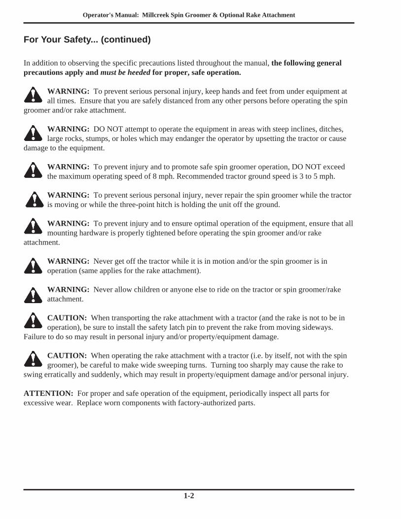
In addition to observing the specific precautions listed throughout the manual, the following generalprecautions apply and must be heeded for proper, safe operation.
WARNING: To prevent serious personal injury, keep hands and feet from under equipment atall times. Ensure that you are safely distanced from any other persons before operating the spin
groomer and/or rake attachment.
WARNING: DO NOT attempt to operate the equipment in areas with steep inclines, ditches,large rocks, stumps, or holes which may endanger the operator by upsetting the tractor or cause
damage to the equipment.
WARNING: To prevent injury and to promote safe spin groomer operation, DO NOT exceedthe maximum operating speed of 8 mph. Recommended tractor ground speed is 3 to 5 mph.
WARNING: To prevent serious personal injury, never repair the spin groomer while the tractoris moving or while the three-point hitch is holding the unit off the ground.
WARNING: To prevent injury and to ensure optimal operation of the equipment, ensure that allmounting hardware is properly tightened before operating the spin groomer and/or rake
attachment.
WARNING: Never get off the tractor while it is in motion and/or the spin groomer is inoperation (same applies for the rake attachment).
WARNING: Never allow children or anyone else to ride on the tractor or spin groomer/rakeattachment.
CAUTION: When transporting the rake attachment with a tractor (and the rake is not to be inoperation), be sure to install the safety latch pin to prevent the rake from moving sideways.
Failure to do so may result in personal injury and/or property/equipment damage.
CAUTION: When operating the rake attachment with a tractor (i.e. by itself, not with the spingroomer), be careful to make wide sweeping turns. Turning too sharply may cause the rake to
swing erratically and suddenly, which may result in property/equipment damage and/or personal injury.
ATTENTION: For proper and safe operation of the equipment, periodically inspect all parts forexcessive wear. Replace worn components with factory-authorized parts.
Operator's Manual: Millcreek Spin Groomer & Optional Rake Attachment
1-3
Safety Labels
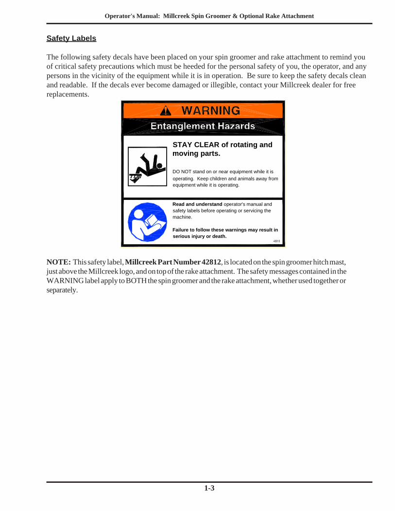
The following safety decals have been placed on your spin groomer and rake attachment to remind youof critical safety precautions which must be heeded for the personal safety of you, the operator, and anypersons in the vicinity of the equipment while it is in operation. Be sure to keep the safety decals cleanand readable. If the decals ever become damaged or illegible, contact your Millcreek dealer for freereplacements.
NOTE: This safety label, Millcreek Part Number 42812, is located on the spin groomer hitch mast,just above the Millcreek logo, and on top of the rake attachment. The safety messages contained in theWARNING label apply to BOTH the spin groomer and the rake attachment, whether used together orseparately.
STAY CLEAR of rotating and moving parts.
DO NOT stand on or near equipment while it is operating. Keep children and animals away from equipment while it is operating.
Read and understand operator's manual and safety labels before operating or servicing the machine.
Failure to follow these warnings may result in serious injury or death.

Operator's Manual: Millcreek Spin Groomer & Optional Rake Attachment
1-4
Operator's Manual: Millcreek Spin Groomer & Optional Rake Attachment
2-1
SECTION 2: UNPACKING & ASSEMBLY
Removing the Shipping Crate and Inspecting All Components
1. Carefully remove the top boards of the spin groomer shipping crate.2. With the assistance of another person(s), carefully lift the spin groomer components out of the
shipping crate. Each spin groomer shipment includes: the three-point spin groomer hitch, thegrooming ring, a hardware bag, and product documentation (manual, warranty card, etc.)NOTE: Approximate weight of the grooming ring ranges from 160 lbs. for the 5 ft. ring upto 230 lbs. for the 7 ft. ring.
3. If you ordered a rake attachment, it is shipped separately in two boxes. One box contains the tworake pieces. The other box contains the arm assembly components, mounting bracket, side stop,and hardware for assembly of the rake attachment.
4. Inspect the spin groomer and/or rake attachment components to ensure that they have beenshipped to you in a satisfactory manner.NOTE: Immediately notify the freight company and your Millcreek dealer in case of shippingdamage, shortage(s), and/or errors.
5. Locate all safety decals and review their content.
Before assembling your spin groomer and/or rake attachment, you must carefully unpack the equipmentfrom the shipping crate and inspect the shipment. Be sure to complete the warranty registration card(s)following unpacking and inspection.
Assembly of the equipment is outlined in the following procedures (please refer to those that apply tothe equipment you ordered):
• Assembling the 3-Point Mast to the Spin Groomer Hitch• Assembling the Spin Groomer Hitch to the Grooming Ring• Assembling the Rake• Attaching the Rake to the Spin Groomer• Connecting the Spin Groomer Hitch to the Tractor• Connecting the Rake Attachment to the Tractor
Detailed parts drawings are provided in the Appendix at the back of this manual (for reference asneeded).
Warranty Registration
For proper warranty registration, Millcreek requires that you fill out the provided warranty registrationcard and return it within 30 days to:
MILLCREEK WARRANTY REGISTRATIONMillcreek Manufacturing Company
34 Zimmerman RoadLeola, PA 17540
Operator's Manual: Millcreek Spin Groomer & Optional Rake Attachment
2-2
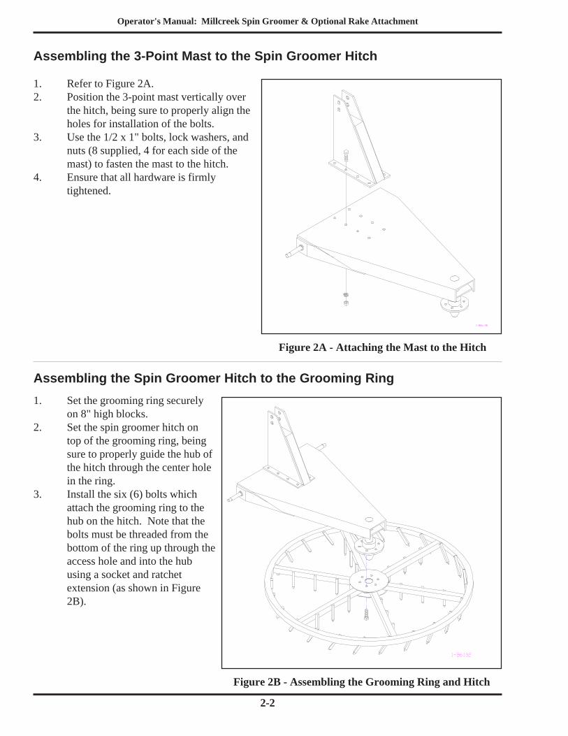
Assembling the Spin Groomer Hitch to the Grooming Ring1. Set the grooming ring securely
on 8" high blocks.2. Set the spin groomer hitch on
top of the grooming ring, beingsure to properly guide the hub ofthe hitch through the center holein the ring.
3. Install the six (6) bolts whichattach the grooming ring to thehub on the hitch. Note that thebolts must be threaded from thebottom of the ring up through theaccess hole and into the hubusing a socket and ratchetextension (as shown in Figure2B).
Figure 2B - Assembling the Grooming Ring and Hitch
Assembling the 3-Point Mast to the Spin Groomer Hitch
1. Refer to Figure 2A.2. Position the 3-point mast vertically over
the hitch, being sure to properly align theholes for installation of the bolts.
3. Use the 1/2 x 1" bolts, lock washers, andnuts (8 supplied, 4 for each side of themast) to fasten the mast to the hitch.
4. Ensure that all hardware is firmlytightened.
Figure 2A - Attaching the Mast to the Hitch
Operator's Manual: Millcreek Spin Groomer & Optional Rake Attachment
2-3
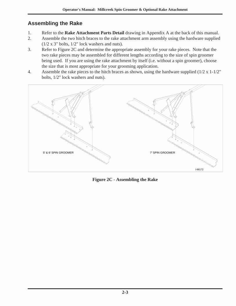
Assembling the Rake1. Refer to the Rake Attachment Parts Detail drawing in Appendix A at the back of this manual.2. Assemble the two hitch braces to the rake attachment arm assembly using the hardware supplied
(1/2 x 3" bolts, 1/2" lock washers and nuts).3. Refer to Figure 2C and determine the appropriate assembly for your rake pieces. Note that the
two rake pieces may be assembled for different lengths according to the size of spin groomerbeing used. If you are using the rake attachment by itself (i.e. without a spin groomer), choosethe size that is most appropriate for your grooming application.
4. Assemble the rake pieces to the hitch braces as shown, using the hardware supplied (1/2 x 1-1/2"bolts, 1/2" lock washers and nuts).
Figure 2C - Assembling the Rake
I-86172
5' & 6' SPIN GROOMER 7' SPIN GROOMER
Operator's Manual: Millcreek Spin Groomer & Optional Rake Attachment
2-4
Bent Pin
Arm Assembly
Side Stop
Hitch
Mounting Bracket
Holes to be Drilled
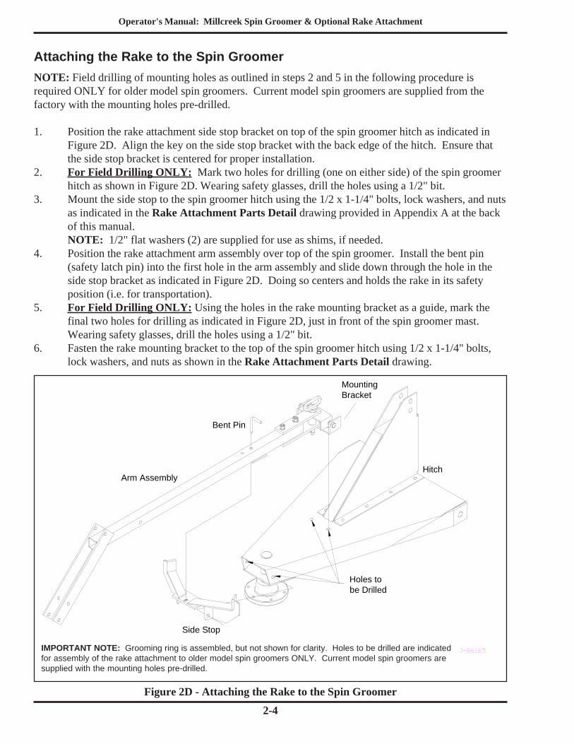
Attaching the Rake to the Spin Groomer
Figure 2D - Attaching the Rake to the Spin Groomer
NOTE: Field drilling of mounting holes as outlined in steps 2 and 5 in the following procedure isrequired ONLY for older model spin groomers. Current model spin groomers are supplied from thefactory with the mounting holes pre-drilled.
1. Position the rake attachment side stop bracket on top of the spin groomer hitch as indicated inFigure 2D. Align the key on the side stop bracket with the back edge of the hitch. Ensure thatthe side stop bracket is centered for proper installation.
2. For Field Drilling ONLY: Mark two holes for drilling (one on either side) of the spin groomerhitch as shown in Figure 2D. Wearing safety glasses, drill the holes using a 1/2" bit.
3. Mount the side stop to the spin groomer hitch using the 1/2 x 1-1/4" bolts, lock washers, and nutsas indicated in the Rake Attachment Parts Detail drawing provided in Appendix A at the backof this manual.NOTE: 1/2" flat washers (2) are supplied for use as shims, if needed.
4. Position the rake attachment arm assembly over top of the spin groomer. Install the bent pin(safety latch pin) into the first hole in the arm assembly and slide down through the hole in theside stop bracket as indicated in Figure 2D. Doing so centers and holds the rake in its safetyposition (i.e. for transportation).
5. For Field Drilling ONLY: Using the holes in the rake mounting bracket as a guide, mark thefinal two holes for drilling as indicated in Figure 2D, just in front of the spin groomer mast.Wearing safety glasses, drill the holes using a 1/2" bit.
6. Fasten the rake mounting bracket to the top of the spin groomer hitch using 1/2 x 1-1/4" bolts,lock washers, and nuts as shown in the Rake Attachment Parts Detail drawing.
IMPORTANT NOTE: Grooming ring is assembled, but not shown for clarity. Holes to be drilled are indicatedfor assembly of the rake attachment to older model spin groomers ONLY. Current model spin groomers aresupplied with the mounting holes pre-drilled.
Operator's Manual: Millcreek Spin Groomer & Optional Rake Attachment
2-5
Connecting the Spin Groomer Hitch to the Tractor
The spin groomer is designed to work with any tractor that uses a standard three-point lift, category "1"hitch.
1. Following assembly of the spin groomer hitch and ring, remove the blocks and set the spingroomer on the ground.
2. Back the tractor into the spin groomer three-point hitch. Ensure that both lower three-point liftarms on the tractor are level (i.e. same distance from the ground).
3. Connect the two lower arms on the tractor hitch to the two hitch pins on the spin groomer.4. Adjust the upper three-point arm in or out until the arm on the tractor matches the top hole on the
spin groomer hitch.5. Install linch retaining pins to hold the spin groomer in place.
CAUTION: To prevent personal injury, ensure that all linch retaining pins are securely installedbefore attempting to lift the spin groomer.
Connecting the Rake Attachment to the TractorNOTE: This procedure applies for grooming applications where the rake is to be connected directly tothe tractor (i.e. by itself, without the spin groomer).
1. Pull the rake attachment into position behind the tractor.2. Align the holes in the rake mounting bracket with the tractor hitch, and install the hitch pin
(supplied with the rake attachment).

Operator's Manual: Millcreek Spin Groomer & Optional Rake Attachment
2-6
Operator's Manual: Millcreek Spin Groomer & Optional Rake Attachment
3-1
SECTION 3: OPERATION
Understanding Spin Groomer and Rake Attachment Operation
Proper and safe operation of the Millcreek spin groomer and rake attachment requires: (1) beingfamiliar with the method of operation and (2) heeding all safety precautions as stated in this manual.
How the Spin Groomer Works
As the tractor moves forward, the spin groomer begins to rotate. As proper speed is achieved, the teethon the grooming ring "dig into" the ground surface and loosen the dirt. The grooming action of the spingroomer is directly related to the depth at which the grooming ring digs into the ground surface. Thissurface penetration is dependent upon the condition of the dirt surface (i.e. hard-packed, granular, wet,dry, etc) and the angle or pitch of the ring.
Control and adjustment of the grooming ring is achieved by (1) lengthening or shortening the top lift armon the three-point hitch and (2) raising or lowering the lower righthand linkage. Note that when youmounted the spin groomer on the tractor hitch, the two lower linkages on the tractor were level.
How the Rake Attachment Works
The addition of a rake attachment with a spin groomer achieves even finer grooming for horse tracks,ball fields, or landscaping applications. Attaching the rake directly to the tractor provides quick and easygrooming capabilities.
The rake is designed so that it can be assembled in several different lengths to match the spin groomersize or desired grooming application width.
The operating angle of the rake is easily adjusted with a spring-loaded lever at the base of the rake armassembly.
Operator's Manual: Millcreek Spin Groomer & Optional Rake Attachment
3-2
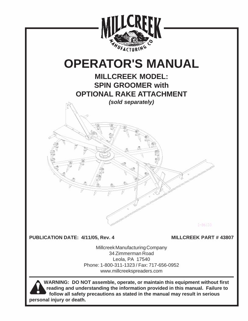
Tractor
12
6
39
Point of greatestpenetration
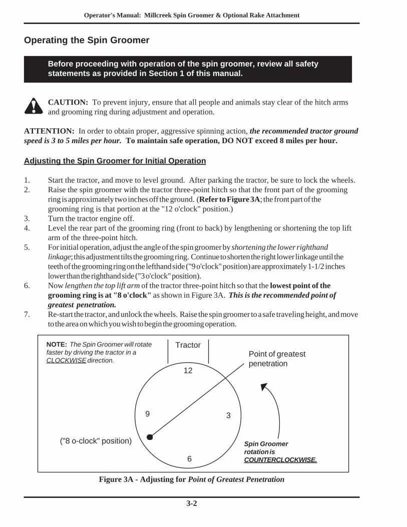
Figure 3A - Adjusting for Point of Greatest Penetration
Operating the Spin Groomer
Before proceeding with operation of the spin groomer, review all safetystatements as provided in Section 1 of this manual.
CAUTION: To prevent injury, ensure that all people and animals stay clear of the hitch armsand grooming ring during adjustment and operation.
ATTENTION: In order to obtain proper, aggressive spinning action, the recommended tractor groundspeed is 3 to 5 miles per hour. To maintain safe operation, DO NOT exceed 8 miles per hour.
Adjusting the Spin Groomer for Initial Operation
1. Start the tractor, and move to level ground. After parking the tractor, be sure to lock the wheels.2. Raise the spin groomer with the tractor three-point hitch so that the front part of the grooming
ring is approximately two inches off the ground. (Refer to Figure 3A; the front part of thegrooming ring is that portion at the "12 o'clock" position.)
3. Turn the tractor engine off.4. Level the rear part of the grooming ring (front to back) by lengthening or shortening the top lift
arm of the three-point hitch.5. For initial operation, adjust the angle of the spin groomer by shortening the lower righthand
linkage; this adjustment tilts the grooming ring. Continue to shorten the right lower linkage until theteeth of the grooming ring on the lefthand side ("9 o'clock" position) are approximately 1-1/2 incheslower than the righthand side ("3 o'clock" position).
6. Now lengthen the top lift arm of the tractor three-point hitch so that the lowest point of thegrooming ring is at "8 o'clock" as shown in Figure 3A. This is the recommended point ofgreatest penetration.
7. Re-start the tractor, and unlock the wheels. Raise the spin groomer to a safe traveling height, and moveto the area on which you wish to begin the grooming operation.
("8 o-clock" position)
NOTE: The Spin Groomer will rotatefaster by driving the tractor in aCLOCKWISE direction.
Spin Groomerrotation isCOUNTERCLOCKWISE.
Operator's Manual: Millcreek Spin Groomer & Optional Rake Attachment
3-3
Operating the Spin Groomer
1. If using the spin groomer with the rake attachment, move the bent pin on the rake arm to theholding position (next hole adjacent to the safety position).
2. Slowly lower the spin groomer until the grooming ring rests on the ground in the "8 o'clock"position (refer to Figure 3A). As the tractor moves forward and achieves the recommendedoperating speed (not to exceed 8 mph), the spin groomer will rotate counterclockwise and beginloosening and grooming the surface.NOTE: The adjustments made in the previous procedure have set the spin groomer to spincounterclockwise during operation; the tractor should then travel in a clockwise direction--doing soprovides optimal grooming results.
3. After observing the rotating action of the spin groomer, you may desire more or less aggressivegrooming action. If this is the case, follow the directions provided in the next procedure for finetuning the spin groomer operation.
Fine Tuning Spin Groomer Penetration
1. To achieve more aggressive grooming (e.g. for hardened, compact surfaces), shorten the lowerrighthand linkage. You may also want to shift the point of greatest penetration towards the"9 o'clock" position when grooming very hard, compact surfaces. Shortening the top lift arm of thethree-point hitch will move the grooming ring's deepest penetration toward the "9 o'clock" position(refer to Figure 3A).
2. To reduce the grooming action (e.g. for non-compacted, lightly textured surfaces), lengthen thelower righthand linkage.
NOTE: Various conditions affect the operation of the spin groomer, including direction of travel andpitch (tilt) of the grooming ring. In some cases it may be necessary to "experiment" with these and othervariables to achieve the desired grooming action.
CAUTION: When operating the rake attachment with a tractor (i.e. by itself, not with the spingroomer), be careful to make wide sweeping turns. Turning too sharply may cause the rake to swing
erratically and suddenly, which may result in property/equipment damage and/or personal injury.
The angle of the rake can be adjusted, as needed, by lifting and re-positioning the spring-loaded lever atthe base of the rake arm assembly. To increase the angle of the rake relative to the ground, adjust thelever toward the rear of the rake.
Operating the Rake Attachment

Operator's Manual: Millcreek Spin Groomer & Optional Rake Attachment
3-4
Operator's Manual: Millcreek Spin Groomer & Optional Rake Attachment
4-1
SECTION 4: MAINTENANCE
Guidelines for Regular Maintenance
Spin Groomer Maintenance
The only moving part on the spin groomer is the hub. The bearings in the hub are packed with greaseat the factory and should remain in good functional operation for the life of the unit.
Periodically inspect the tines for looseness or damage. Tighten and/or replace as needed. When spingroomer is used heavily, inspect tines at least once a month.
To replace tines:• Refer to the Spin Groomer Parts Detail drawing in Appendix A at the back of this
manual.• Remove the stop nut and bolt holding the tine in the bracket.• Open the bracket to remove the damaged tine. You may need to tap lightly on the tine
with a hammer to loosen it from the bracket.• Install the new tine in the bracket. Re-install the bolt and stop nut to tighten the
bracket around the tine.

Operator's Manual: Millcreek Spin Groomer & Optional Rake Attachment
4-2
Operator's Manual: Millcreek Spin Groomer & Optional Rake Attachment
A-1
APPENDIX A: PARTS REFERENCE
The following information is provided for your reference in understanding how the spin groomer isassembled and how spare parts can be identified and ordered properly.
General Spin Groomer Specifications
Spin Groomer Model Weight Crated Shipping Wt. Required Tractor HP
5 ft. 210 lbs. 380 lbs. 20
6 ft. 240 lbs. 445 lbs. 25
7 ft. 280 lbs. 520 lbs. 30
Rake 88 lbs. 92 lbs. (total for 2 boxes) 5**
**(when rake is used by itself)
IMPORTANT NOTE: The spin groomer width should be at least one foot wider than the width of the reartractor tires.
Ordering Information
When ordering replacement parts, please provide the following information to your local Millcreek dealer:• Model and Serial Number of the unit• Part Number and Description as it appears on the following drawings/parts lists
Operator's Manual: Millcreek Spin Groomer & Optional Rake Attachment
A-2
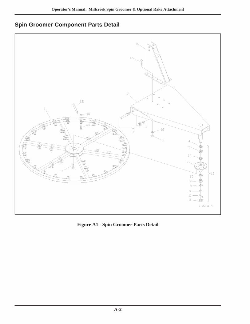
Spin Groomer Component Parts Detail
Figure A1 - Spin Groomer Parts Detail
Operator's Manual: Millcreek Spin Groomer & Optional Rake Attachment
A-3
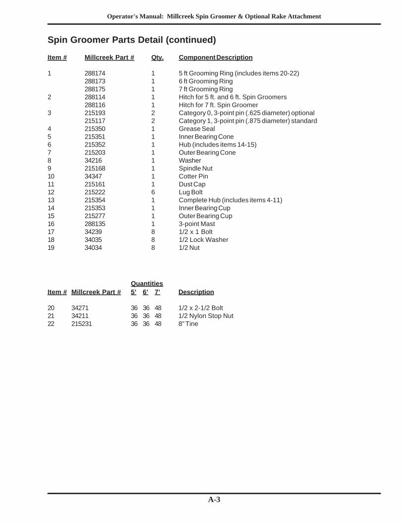
Spin Groomer Parts Detail (continued)
Item # Millcreek Part # Qty. Component Description
1 288174 1 5 ft Grooming Ring (includes items 20-22)288173 1 6 ft Grooming Ring288175 1 7 ft Grooming Ring
2 288114 1 Hitch for 5 ft. and 6 ft. Spin Groomers288116 1 Hitch for 7 ft. Spin Groomer
3 215193 2 Category 0, 3-point pin (.625 diameter) optional215117 2 Category 1, 3-point pin (.875 diameter) standard
4 215350 1 Grease Seal5 215351 1 Inner Bearing Cone6 215352 1 Hub (includes items 14-15)7 215203 1 Outer Bearing Cone8 34216 1 Washer9 215168 1 Spindle Nut10 34347 1 Cotter Pin11 215161 1 Dust Cap12 215222 6 Lug Bolt13 215354 1 Complete Hub (includes items 4-11)14 215353 1 Inner Bearing Cup15 215277 1 Outer Bearing Cup16 288135 1 3-point Mast17 34239 8 1/2 x 1 Bolt18 34035 8 1/2 Lock Washer19 34034 8 1/2 Nut
QuantitiesItem # Millcreek Part # 5’ 6’ 7’ Description
20 34271 36 36 48 1/2 x 2-1/2 Bolt21 34211 36 36 48 1/2 Nylon Stop Nut22 215231 36 36 48 8" Tine
Operator's Manual: Millcreek Spin Groomer & Optional Rake Attachment
A-4
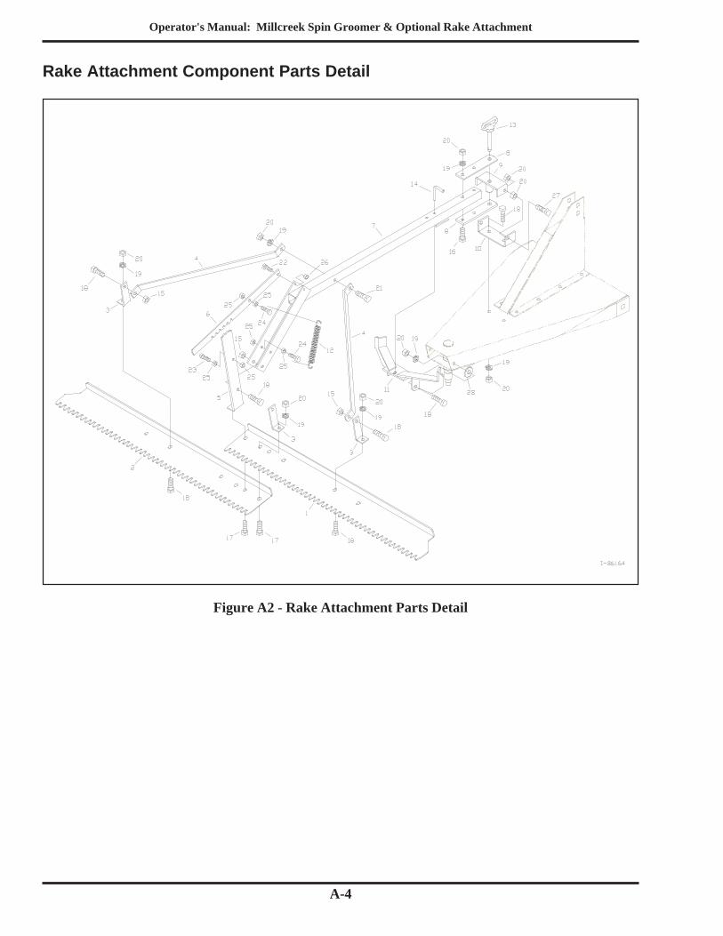
Rake Attachment Component Parts Detail
Figure A2 - Rake Attachment Parts Detail
Operator's Manual: Millcreek Spin Groomer & Optional Rake Attachment
A-5
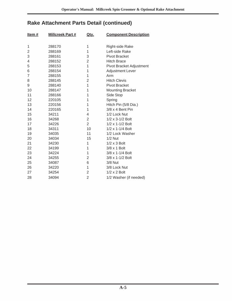
Rake Attachment Parts Detail (continued)
Item # Millcreek Part # Qty. Component Description
1 288170 1 Right-side Rake2 288169 1 Left-side Rake3 288161 3 Pivot Bracket4 288152 2 Hitch Brace5 288153 1 Pivot Bracket Adjustment6 288154 1 Adjustment Lever7 288155 1 Arm8 288145 2 Hitch Clevis9 288140 1 Pivot Bracket10 288147 1 Mounting Bracket11 288166 1 Side Stop12 220105 1 Spring13 220156 1 Hitch Pin (5/8 Dia.)14 220165 1 3/8 x 4 Bent Pin15 34211 4 1/2 Lock Nut16 34268 2 1/2 x 3-1/2 Bolt17 34226 2 1/2 x 1-1/2 Bolt18 34311 10 1/2 x 1-1/4 Bolt19 34035 11 1/2 Lock Washer20 34034 15 1/2 Nut21 34230 1 1/2 x 3 Bolt22 34199 1 3/8 x 1 Bolt23 34224 1 3/8 x 1-1/4 Bolt24 34255 2 3/8 x 1-1/2 Bolt25 34087 6 3/8 Nut26 34220 1 3/8 Lock Nut27 34254 2 1/2 x 2 Bolt28 34094 2 1/2 Washer (if needed)

Operator's Manual: Millcreek Spin Groomer & Optional Rake Attachment
A-6