Embed Size (px)
Citation preview

Solar to Fuels Conversion Technologies
AN MIT FUTURE OF SOLAR ENERGY STUDY WORKING PAPER

AN MIT FUTURE OF SOLAR ENERGY STUDY WORKING PAPER
Solar to Fuels Conversion TechnologiesHarry L. Tuller
Department of Materials Science and Engineering
Massachusetts Institute of Technology

i AN MIT FUTURE OF SOLAR ENERGY STUDY WORKING PAPER
Energy InitiativeMassachusetts Institute of Technology
Copyright © 2015 Massachusetts Institute of Technology. All rights reserved.
Incorporated in the cover art is an image of the Gemasolar solar thermal plant, owned by Torresol Energy. ©SENER
http://mitei.mit.edu/futureofsolar
MITEI-WP-2015-03

Solar Alternative Fuels 1
1. Introduction
Fossil fuels are broadly used for transporta-tion, electricity generation, industrial processes, and heating. Given their ready availability, high energy density,i and ease of handling, storage, and transport, they supply more than 80% of the world’s overall energy needs, and 96% of the transportation sector’s energy demand, with much of the remaining 4% of transportation energy being electricity generated in plants that burn fossil fuels. At the same time, the combustion of fossil fuels to extract their stored chemical energy is a major source of greenhouse gas emissions, mostly carbon dioxide (CO2), and thus contributes to global warming. While interest in and utilization of solar energy as a key alternative clean energy source have grown rapidly in recent years, solar technology deployment has been largely directed to electricity generation. While important, recent advances in solar electricity generation do not address the continued need for high-energy-density fuels for transportation, heating, and industrial process uses, which together account for roughly 70% of overall energy require-ments. This working paper discusses options for converting solar energy into fuels, largely through the solar-driven conversion of water and CO2 into fuels and chemicals. This con version would be achieved in a solar refi nery,1 where solar energy acts on CO2 captured from fl ue gas emissions, together with water, to generate solar fuels. These fuels, which can be sustainably produced in liquid or
gaseous form, offer multiple benefi ts in terms of grid stability, energy security, compatibility with existing infrastructure, and climate change mitigation. The opportunities and challenges associated with sourcing, producing, storing, and distributing solar fuels are the focus of this working paper.
2. Solar Alternative Fuels
Increasingly, electricity, including the widespread electrifi cation of transportation, is being seen as playing a pivotal role in achieving deep cuts in greenhouse gas emis-sions, such as the reductions — at 80% below 1990 levels — proposed for California by 2050.2 Even more aggressive goals recently articulated by the White House, aim to derive 80% of electricity from clean energy sources by 2035 and reduce greenhouse gas emissions 17% by 2020 and 83% by 2050 (relative to a 2005 baseline).3 Given that electricity accounts for 30% of global energy consumption, and without an unexpected breakthrough in electricity storage,ii alternative, low-carbon fuels will be needed to satisfy the remaining 70% of global energy requirements, particu-larly for transportation, manufacturing, and heating.4 To get a sense of the magnitude of this challenge, one need only note that the U.S. registered light-duty vehicle (LDV) fl eet of over 234 million vehicles consumes 8.4 million barrels of oil to travel 7.3 billion miles on a daily basis. This represents nearly 10% of total petroleum liquids consumption worldwide.5,6,7,8
iOne liter of gasoline delivers 35 MJ of energy. This compares with the global average per capita energy consumption of ~900 MJ/day. Alternatively, one can compare the energy stored per kg of weight or per liter of volume of the storage medium: gasoline (46 MJ/kg; 32.4 MJ/L), hydrogen-compressed (123 MJ/kg; 5.6 MJ/L), lithium ion battery (0.36-0.88 MJ/kg; 0.9-2.63 MJ/L, and lead acid battery (0.17 MJ/kg; 0.56 MJ/L).
i iFor example by low-cost electricity to hydrogen conversion via electrolysis, as discussed later.

Solar energy, among all of the carbon-free energy sources, is viewed by some experts as the alternative with the greatest intermediate to long-term potential to replace fossil fuels.9 For this to happen, however, two important challenges must be addressed. The fi rst is providing adequate energy storage capabilities for solar-generated electricity, given the inter-mittent character of the solar resource. The second, perhaps more important challenge, is utilizing solar energy to aid in the production of clean alternative fuels for the transportation, industrial, and housing sectors.10
Solar energy has, until now, accounted for a relatively small fraction of the overall energy supply, with its fl uctuating contributions to the grid controlled and compensated by thermal generation (fossil-fuel combustion). As solar and wind penetration increases, however, the intermittency of these two energy sources seriously compromises the stability and quality of grid power. This issue has already begun to demand urgent attention in Germany where 28.9 terawatt-hours (TWh) of electricity (equal to 6.6% of total production)iii was generated by solar sources in the fi rst 11 months of 2013, with an additional 4 TWh added in the fi rst half of 2014.11,12 During this same period, 83.3 TWh (equal to 19.1% of Germany’s total electricity production) was generated by nuclear plants, which are slated for shutdown by 2021.13 While dependence on intermittent renewable energy sources is not yet quite so high in the United States, where solar and wind accounted for 0.23% and 4.13% of overall electricity production in 2013, respectively,14 the relentless decline in PV module prices has continued at a rate of 5%–7% annually for the past decade.15 The U.S. Energy Information Administration now
expects utility-scale solar generating capacity to increase by more than 60% between the end of 2014 and the end of 2016, while wind capacity is expected to increase by about 23% over the same time period.16 While these projections may be optimistic, and may assume the continued existence of various government subsidies, there is little doubt that generation from these intermittent energy sources will continue to show signifi cant growth. This creates a strong incentive to bring into play, as quickly as possible, alternative storage systems that are both robust and carbon-neutral to ensure grid stability in the coming decades.
A fi gure-of-merit for the storage of electrical energy generated by intermittent sources, defi ned as the ratio of the value of stored electricity to the cost of storage, is useful in comparing alternate storage technologies. For example, assuming a one-day storage period, the fi gure-of-merit for electrical energy stored chemically via hydrogen produced by electrol-ysis is 12.7. While this is much higher — taking into account the cost, life, and effi ciency of the process — than electrical battery storage, which has a fi gure-of-merit of 1.0,17 these fi gures do not account for the effi ciency of producing hydrogen or converting hydrogen back to electricity. If one combines the effi ciency of electrolysis cells, at approxi-mately 75%, with that of a combined cycle gas and steam turbine generator running on hydrogen (about 60%), the result is a full cycle electricity–fuel–electricity effi ciency of up to 45%.18 More typical round trip effi ciencies are reportedly closer to 30%, making the attrac-tion of hydrogen vs. battery storage less clear in the short term.19 Hydrocarbon fuels with higher energy densities can also be synthesized
2 AN MIT FUTURE OF SOLAR ENERGY STUDY WORKING PAPER
iii If wind, the other major intermittent source of electric power, is included, the contribution from renewable sources in Germany over this time period increases to 17% of the total.

Solar Alternative Fuels 3
by combining hydrogen with CO2 captured, for example, from coal-burning plants. Longer term, as fossil-fuel generating plants are replaced by renewable sources, CO2 could be captured from non-combustion sources such as cement plants.
Siemens reports that synthetic natural gas (i.e., methane [CH4]) can be generated, on a pilot scale, from hydrogen and CO2 with up to 80% effi ciency.18 Synthetic natural gas has three times the energy density, on a volume basis, of hydrogen. Given the central role that chemical fuels already play in electricity generation, the conversion of solar energy into chemical fuels that are capable of being used in the existing distribution and end-use infrastructure would be highly desirable.19 Synthetic gas, stored and distributed like conventional natural gas, could then be used to power vehicles or in heating systems — in addition to being used to generate electricity — on an as needed basis. In Germany, for example, existing natural gas storage capacity — at more than 200 TWh — would be suffi cient to satisfy consumption for several months.20 Moreover, synthetic hydro-carbons can be used in a variety of additional ways, including in the production of fertilizer, plastics, and pharmaceuticals, as well as for transportation and heating.21
Like most other countries, the United States is nearly completely dependent on petroleum for transportation; in fact, petroleum use for transportation accounts for about one-third of total annual U.S. CO2 emissions.22 Worldwide, the transportation sector accounted for 19% of global energy demand in 2010 and oil supplied 96% of this demand, with the rest coming from natural gas, biofuels, and elec-tricity.23 Government regulations mandating improved vehicle fuel effi ciency and the increasing electrifi cation of transportation via the introduction of hybrid and plug-in
vehicles will help reduce dependence on fossil fuels. However, many forms of transportation, including long-haul passenger vehicles, ships, trucks, and aircraft will continue to require high-energy-density, but ideally carbon-free or carbon-neutral fuels.
2.1 BASIC SOLAR FUELS
Solar fuels are not new. The photo-assisted synthesis (photosynthesis) of chemical fuels, in the form of plant matter, is fundamental to life on Earth and supports all current biomass. The same process, over geological time, produced the fossil fuels on which human civilization has depended for the vast majority of its energy needs for the past century and earlier. Due to the relative ineffi ciency of natural photosynthesis, the use of all cultivat-able land on Earth to produce biofuels would not satisfy humanity’s projected energy needs in the coming decades, particularly if one takes into account the energy needed to harvest, store, distribute, and convert biomass into useful chemical fuels.24 An alternative approach that obviates the need to set aside vast tracts of arable land is to replicate the essential elements of photosynthesis found in natural organisms with artifi cial systems. On an industrial scale, one can visualize a solar refi nery (see Figure 1) that converts readily available sources of carbon and hydrogen, in the form of CO2 and water (H2O), to useful fuels, such as methanol (CH3OH), using energy sourced from a solar utility.1 The solar utility, optimized to collect and concentrate solar energy and/or convert solar energy to electricity or heat, can be used to drive the electrocatalytic, photoelectrochemical (PEC), or thermochemical reactions needed for conversion processes. For example, electricity provided by PV cells can be used to generate hydrogen electrochemically from water via an electrolysis (electrocatalytic) cell.

4 AN MIT FUTURE OF SOLAR ENERGY STUDY WORKING PAPER
Figure 1 Schematic of a Solar Refi nery1
Schematic of a Solar Refi nery and solar fuel feedstocks (CO2, H2O, and solar energy) captured onsite or transported to the refi nery. The Solar Utility provides energy in the form of heat, electricity or photons used to convert the CO2 and H2O into fuels either by direct CO2 reduction or solar activation of CO2/H2O to CO/H2 and subsequent catalytic conversion to fuels (e.g., via methanol synthesis or by the Fischer-Tropsch method. Color code: yellow – ambient; red – elevated temperatures.1
Hydrogen, the most elemental fuel, has many attractive attributes — it is clean burning (water being the only byproduct of hydrogen combustion) and can be effi ciently converted back to electricity via fuel cells. However, hydrogen lacks volumetric energy density and cannot be easily stored and distributed like hydrocarbon fuels. Rather than utilizing solar-generated hydrogen directly and primarily as a fuel, its utility is much greater — at least in the short to intermediate termiv — as an onsite fuel for converting CO2 to CH4 or for generating syngas, heat, or electricity.25
Reacting CO2 with hydrogen (H2) not only provides an effective means for storing CO2 (in methane, for example), it also produces a fuel that is much easier to store, distribute, and utilize within the existing energy supply infrastructure. Thus, recycling CO2 to produce a hydrocarbon fuel would open the transpor-tation sector to far greater reliance on renew-able energy beyond what is currently feasible with rechargeable electric vehicles (at present, such vehicles comprise fewer than 3% of all vehicles sold in the United States).8 The idea of converting CO2, a product of combustion, to
iv Until an effi cient means for storing hydrogen becomes widely available.

Solar Alternative Fuels 5
useful hydrocarbon fuels by harnessing solar energy is attractive in concept. However, signifi cant reductions in CO2 capture costs and signifi cant improvements in the effi ciency with which solar energy is used to drive chem-ical conversions must be achieved to make the solar refi nery a reality. We address these issues in greater detail below.
Solar energy collected and concentrated within a solar utility (see Figure 1) can be harnessed in different ways: (1) PV systems could convert sunlight into electricity, which in turn, could be used to drive electrochemical (electrolysis) cells that decompose inert chemical species such as H2O or CO2 into useful fuels; (2) PEC or photocatalytic systems could be designed wherein electrochemical decomposition reactions (like the reactions in the previous example) are driven directly by light, without the need to separately generate electricity; and (3) photothermal systems could be used either to heat working fl uids or help drive desired chemical reactions such as those connected with thermolysis, thermochemical cycles, etc. (see Figure 1). Each of these approaches can, in principle, be used to generate environmen-tally friendly solar fuels that offer “effi cient production, suffi cient energy density, and fl exible conversion into heat, electrical, or mechanical energy.” 26 The energy stored in the chemical bonds of a solar fuel could be released via reaction with an oxidizer, typically air, either electrochemically (e.g., in fuel cells) or by combustion, as is usually the case with fossil fuels. Of the three approaches listed here, only the fi rst (PV and electrolysis cells) can rely on infrastructure that is already installed today at a scale that would have the potential to signifi cantly affect current energy needs. The PEC and photothermal approaches, though they hold promise for achieving simplifi ed assembly and/or high energy conversion effi ciencies, require considerable
development before moving from the labora-tory into pilot-scale and commercially viable assemblies. Remaining sections of this working paper discuss the status of these three approaches and the challenges that must be overcome to advance each of them.
Given that, the contribution of artifi cially produced solar fuels, such as hydrogen and methane, remains extremely small at present, exceptional efforts — particularly to reduce costs — are needed to bring these clean and sustainable fuels up to meaningful levels. Critical challenges that will need to be over-come include improving the sourcing and collection of CO2, increasing the effi ciency of solar-assisted catalytic conversion of CO2 and H2O into fuels, extending device lifetimes, reducing costs, and investing in infrastructure upgrades to reduce the large gap between current laboratory demonstrations and deployable technology. These challenges are discussed here in terms of key candidate solar fuels.
Chapters 2 and 3 of the MIT Future of Solar Energy study27 present a detailed analysis of options for generating electricity from sunlight via PV cells. A few highlights from that anal-ysis are worth repeating here by way of providing context for this working paper. According to the Solar Electric Power Association, installed solar power generating capability in the United States totaled 10.7 GW as of 2013. PV accounted for most of this capability, roughly half of which (48%) was provided by utility-scale installations. Another 25 GW of solar generation capacity is projected to be installed by 2017.28 Solar thermal power, also referred to as concentrated solar power (CSP), represents a growing but much smaller component of installed solar power generating capacity. As of 2013, 926 MW of CSP capacity had been installed in the

6 AN MIT FUTURE OF SOLAR ENERGY STUDY WORKING PAPER
United States, but an additional 800 MW as anticipated in 2014 with a total of 3.2 GW of capacity projected by 2017.28 While generally more costly than PV, CSP enables lower-cost thermal (rather than electrical) energy storage, which is key to overcoming issues related to solar energy’s intermittency. It is worth noting that of the approximately 1.06 TW of electrical power capacity in the United States in 2012,29 10.7 GW of solar power would represent only 1% of the total.
2.1.1 Hydrogen Production
Hydrogen has been recognized for some time as providing a potential foundation for a clean, fl exible, and secure energy future. The fact that it is accessible in the form of water makes hydrogen highly attractive. When hydrogen is used as a fuel, either by combustion or electro-chemically in a fuel cell, the only byproduct is water — a feature that promises an emission-free environment. While the combustion of hydrogen produces more energy on a mass basis (39.5 kWh/kg)v than the combustion of any other fuel — e.g., 2.4 and 2.8 times the energy of methane and gasoline combustion, respectively30 — hydrogen has low energy density by volume. In fact, at 2.8 kWh per liter, the energy density of hydrogen is 3.5 times lower than that of gasoline. Since liquefying hydrogen is highly energy intensive and thus not practical, hydrogen is most effectively stored as a gas in high-pressure tanks. Given its simple chemical structure, it is one of a very small group of fuels capable of being used in low-temperature fuel cells, thereby making it the fuel of choice for fuel-cell-powered vehicles.31
Since hydrogen in its molecular form does not occur in nature, it is not an energy source and must be produced. In this sense hydrogen is rather more like electricity, a convenient energy carrier, and, as will become evident, a strong synergy exists between electricity, hydrogen, and other renewable energy sources.32 Hydrogen production today is actually a large net generator of CO2 emissions, with 13.7 kilograms (kg) of CO2 produced for every kg of H2, on average.33 At present, approximately 96% of hydrogen is derived from fossil fuels and only 4% is produced via electrolysis.34 Hydrogen is produced in high volumes (current global annual production exceeds 70 million metric tons, while annual U.S. production is projected to total 11 million metric tons in 2016),35 largely via steam reforming of natural gas (methane)vi for use in fertilizers and in the hydrocracking of heavy petroleum and the manufacture of methanol and hydrochloric acid. The value of hydrogen production worldwide is expected to reach $163 billion by 2015.35,36 Hydrogen produced via water electrolysis is generally more expen-sive than by large-scale fuel processing tech-niques, although it becomes more attractive when produced onsite. However, if fossil fuels are used to generate the electricity that drives the electrolysis process, resulting emissions are actually higher than for natural gas reforming.37 This points to the need and opportunity to harness renewable sources of energy, particularly intermittent sources such as solar and wind, for hydrogen production. The next sections review the two main options being considered for generating hydrogen using solar energy.
v Higher Heating Value (HHV), evaluated at room temperature and 1 atm pressure.
vi Steam reforming reaction: CH4 + H2O çè CO + 3 H2 (followed by water gas shift reaction CO + H2O çè CO2 + H2 to further increase H2 yield).

Solar Alternative Fuels 7
2.1.1.1 Water Electrolysis
Water (H2O) can be decomposed into its elemental components hydrogen (H2) and oxygen (O2) by passing current between two electrodes immersed in an electrolysis cell. Oxygen is evolved at the positive electrode (anode), hydrogen is evolved at the negative electrode (cathode), and the two are separated from each other by an ionic conducting liquid or solid electrolyte that selectively transports H+, OH- or O2- ions across the cell, depending on the nature of the electrolysis cell. A cell voltage of at least 1.23 V is required. In prac-tice, however, voltages closer to 1.9 V are needed to achieve reasonable current densities, and corresponding fl uxes of generated hydrogen and oxygen gases. The need for higher voltage to overcome ohmic (resistive) losses and electrode over-potentials in turn reduces electrical-to-chemical energy conver-sion effi ciencies. There is thus great interest in identifying and optimizing catalysts that can accelerate the oxygen oxidation reaction at the anode and the hydrogen reduction reaction at the cathode, thereby reducing electrode over-potentials.
Two approaches to harnessing solar energy to drive the electrolysis reaction are possible and are being pursued. The most obvious approach is to drive a conventional water electrolyzer using the electrical output of PV devices. Given that typical conversion effi ciencies are 11.5%–17.5% for commercial PV systems and 63%–73% for electrolyzers overall conversion effi ciencies of approximately 12% can be expected and have been reported for opti-mized, combined PV–electrolyzer systems.1,38 The most obvious advantage of this approach is that both PV and electrolysis systems are commercially available, although large-scale electrolysis systems are not nearly as exten-sively available as PV systems.
An alternative approach, still in the experi-mental stage, is the use of photo-electrolytic systems that combine the functions of light collection, charge separation, and electrolysis in a single cell. This is achieved by replacing one or both of the metallic electrodes in a conventional electrolysis cell with a semicon-ductor. The advantage of this approach is that it offers opportunities to minimize cost by eliminating redundant support structures and energy losses associated with cell interconnec-tions. At the same time, it has been diffi cult to simultaneously achieve high conversion effi ciencies and long-term operating stability because the semiconductors that offer the highest effi ciencies are susceptible to corrosion during cell operation. Several recent advances address these limitations. These include: (1) combining the PV and electrolysis or PEC cell into a single integrated tandem photo-electro-chemical cell, with theoretical solar-to-hydrogen conversion effi ciencies of 31.1% at one Sun illumination,39 (2) protecting the semiconductors in PEC cells from corrosion,40 (3) introducing low-cost Earth-abundant catalysts,41 and (4) improving active area and optical absorptivity through the use of nano-structuring or nanowires.42 These options are described in the next sections.
2.1.1.1.1 Combined PV-Electrolysis Systems
The MIT Future of Solar Energy study27 compares various PV materials (e.g., crystalline and amorphous silicon (Si), cadmium telluride (CdTe), gallium arsenide (GaAs) or copper indium gallium diselenide (CIGS)) and device designs in terms of their relative costs, solar to electricity conversion effi ciencies, long-term stability, and environmental impact. Overall, it is fair to say that a number of PV systems are now commercially available, with the option to trade off lifetime costs and effi ciency depending on the particular application being considered. That being the case, this paper

8 AN MIT FUTURE OF SOLAR ENERGY STUDY WORKING PAPER
reviews options for electrolyzers, which are generally less advanced in their development and commercialization.
Water electrolysis is a relatively mature tech-nology, with hydrogen production capacities ranging from a few cubic centimeters per minute (cm3/min) to thousands of cubic meters per hour (m3/h). Key performance parameters for electrolyzer systems are conver-sion effi ciency (electrical to chemical energy (H2)); current density (amps/unit area), which in turn determines the hydrogen fl ux density, durability, scalability, and cost; and, for some designs, reliance on noble metals such as platinum. The three major types of electro-lyzers are based on aqueous alkaline (OH-), solid polymer (H+), and solid oxide (O2-) ionic conducting electrolytes. The most commer-cially developed option is the alkaline cell, which uses a 30% potassium hydroxide elec-trolyte solution that operates at 80°C–90°C and pressures to 25–30 bar. Cathodes and anodes are porous nickel (Ni) coated respec-tively with platinum at the cathode and with metal oxides at the anode. Such cells exhibit good durability (10–20 yrs) and have effi cien-cies of 63%–73%, but suffer from relatively low current densities, which means that larger systems are required to produce equivalent volumes of hydrogen.1,32 The proton exchange membrane (PEM) electrolyzer, which uses a polymer-based Nafi on proton conducting membrane and has a working temperature of about 90°C, can operate at considerably higher current densities than the alkaline cell and therefore can be more compact, but its conver-sion effi ciency is lower — on the order of 56%. The PEM cell also suffers from reliance on precious metal electrocatalysts (typically platinum [Pt] dispersed on carbon), a costly membrane (Nafi on), and potential degrada-tion in performance due to catalyst coarsening that reduces the active electrode area over
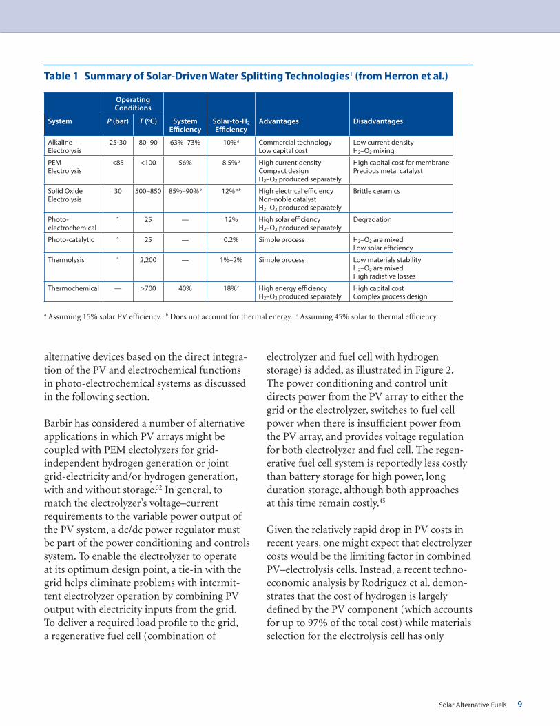
time. The solid oxide electrolyzer cell utilizes a ceramic oxygen ion conducting electrolyte (typically yttria stabilized zirconia [YSZ] or Y0.1Zr0.9O2), and operates at much higher temperatures (500°C–850°C) and at pressures of 30 bar. The higher operating temperature allows for a signifi cant reduction in electrical power consumption (effi ciencies as high as 85%–90% have been reported) and for the use of non-noble metal electrodes (typically Ni-YSZ cermet cathode and a ceramic lanthanum strontium manganese oxide (LSMO) anode).43 Reduced ohmic and over-potential losses also allow for considerably higher current densities and more compact designs. The high operating temperatures and brittle nature of the oxide components, however, create additional challenges vis-à-vis reduced lifetimes and materials and fabrica-tion costs. The key features of these electrolysis systems are summarized in Table 1, which is taken from Herron et al.1 Table 1 and includes estimates of projected solar-to-H2 conversion effi ciencies, which range from 8.5% for PEM to 12% for solid oxide electrolysis cells, assuming a 15% solar-to-electricity PV con version effi ciency. To increase the energy effi ciency of electrolysis, the cell voltage must be reduced (effi ciency ~1.23 V/cell operating voltage). This in turn requires better catalysts or a decrease in current density. Reductions in current density, however, translate to a reduc-tion in the rate of hydrogen production, which tends to increase required electrode area and thus cost.44 Thus catalyst development remains a key target in nearly all electrochemical devices. Furthermore, besides the basic cell-stack, so-called balance-of-plant components, i.e., power supply/voltage regulator, water supply and circulation, gas separators, heat exchanger, controls and instrumentation, add signifi cant costs to these systems. These balance-of-plant costs should be kept in mind when considering the relative attractiveness of
Solar Alternative Fuels 9
alternative devices based on the direct integra-tion of the PV and electrochemical functions in photo-electrochemical systems as discussed in the following section.
Barbir has considered a number of alternative applications in which PV arrays might be coupled with PEM electolyzers for grid-independent hydrogen generation or joint grid-electricity and/or hydrogen generation, with and without storage.32 In general, to match the electrolyzer’s voltage–current requirements to the variable power output of the PV system, a dc/dc power regulator must be part of the power conditioning and controls system. To enable the electrolyzer to operate at its optimum design point, a tie-in with the grid helps eliminate problems with intermit-tent electrolyzer operation by combining PV output with electricity inputs from the grid. To deliver a required load profi le to the grid, a regenerative fuel cell (combination of
electrolyzer and fuel cell with hydrogen storage) is added, as illustrated in Figure 2. The power conditioning and control unit directs power from the PV array to either the grid or the electrolyzer, switches to fuel cell power when there is insuffi cient power from the PV array, and provides voltage regulation for both electrolyzer and fuel cell. The regen-erative fuel cell system is reportedly less costly than battery storage for high power, long duration storage, although both approaches at this time remain costly.45
Given the relatively rapid drop in PV costs in recent years, one might expect that electrolyzer costs would be the limiting factor in combined PV–electrolysis cells. Instead, a recent techno-economic analysis by Rodriguez et al. demon-strates that the cost of hydrogen is largely defi ned by the PV component (which accounts for up to 97% of the total cost) while materials selection for the electrolysis cell has only
Table 1 Summary of Solar-Driven Water Splitting Technologies1 (from Herron et al.)
OperatingConditions
System P (bar) T (ºC) System Effi ciency
Solar-to-H2 Effi ciency
Advantages Disadvantages
Alkaline Electrolysis
25-30 80–90 63%–73% 10%a Commercial technologyLow capital cost
Low current densityH2–O2 mixing
PEM Electrolysis
<85 <100 56% 8.5%a High current densityCompact designH2–O2 produced separately
High capital cost for membranePrecious metal catalyst
Solid Oxide Electrolysis
30 500–850 85%–90%b 12%a,b High electrical effi ciencyNon-noble catalystH2–O2 produced separately
Brittle ceramics
Photo-electrochemical
1 25 — 12% High solar effi ciencyH2–O2 produced separately
Degradation
Photo-catalytic 1 25 — 0.2% Simple process H2–O2 are mixedLow solar effi ciency
Thermolysis 1 2,200 — 1%–2% Simple process Low materials stabilityH2–O2 are mixedHigh radiative losses
Thermochemical — >700 40% 18% c High energy effi ciencyH2–O2 produced separately
High capital costComplex process design
a Assuming 15% solar PV effi ciency. b Does not account for thermal energy. c Assuming 45% solar to thermal effi ciency.

10 AN MIT FUTURE OF SOLAR ENERGY STUDY WORKING PAPER
minor effects.46 This fi nding follows from the fact that the area of the PV array may need to be more than 100 times that of the electrolysis cell given the much lower current densities (<10 mA/cm-2) in unconcentrated solar cells as compared to electrolyzers, which can operate at current densities above 1 A cm-2. As a consequence, PV cells operating with solar concentrators can be expected to lead to considerable cost savings. The authors esti-mate that optimized systems can achieve costs below $2.90 per kg of hydrogen produced, including compression and distribution costs.46 This compares favorably with the U.S. Department of Energy’s stated goal of reducing the cost of hydrogen production to $2.00–$4.00 per gallon of gasoline equiva-lent (gge)vii delivered and dispensed by 2020.31
2.1.1.1.2 Photoelectrochemical Water Splitting
A photoelectrolysis cell, illustrated in Figure 3, is inherently more attractive since it combines the functions of PV cells and conventional electrolysis cells in a single unit. Light (photons) absorbed in a photoelectrode create electron–hole pairs that are separated by internal electric fi elds, as in PV cells. After separation, the holes drive the respective water oxidation reaction (forming O2) at the photo-anode and electrons drive the water reduction reaction (forming H2) at the photocathode. Similar cells can be designed with only a photocathode or photoanode with the counter electrode typically being made of platinum. Key challenges to overcome include relatively low solar-to-hydrogen conversion effi ciencies (typically under 5%), and photo-assisted
Figure 2 Schematic Diagram of Integrated PV–Hydrogen Utility Energy System
Source: U.S. Department of Energy
vii The energy content of a gallon of gasoline and a kilogram of hydrogen are approximately equal on a lower heating value basis; a kilogram of hydrogen is approximately thus equal to a gallon of gasoline equivalent (gge) on an energy content basis.

Solar Alternative Fuels 11
corrosion of the covalently bonded semicon-ducting photoelectrodes that support higher conversion effi ciencies. Semiconducting oxides are typically more resistant to photo-corrosion and are composed of non-toxic, Earth-abundant elements, but their higher band gap energies limit the absorption of a signifi cant fraction of the incident solar radiation at longer wavelengths and are less effi cient at separating the photo-generated electrons and holes and at driving the oxygen and hydrogen generation reactions at the electrode–liquid interfaces.
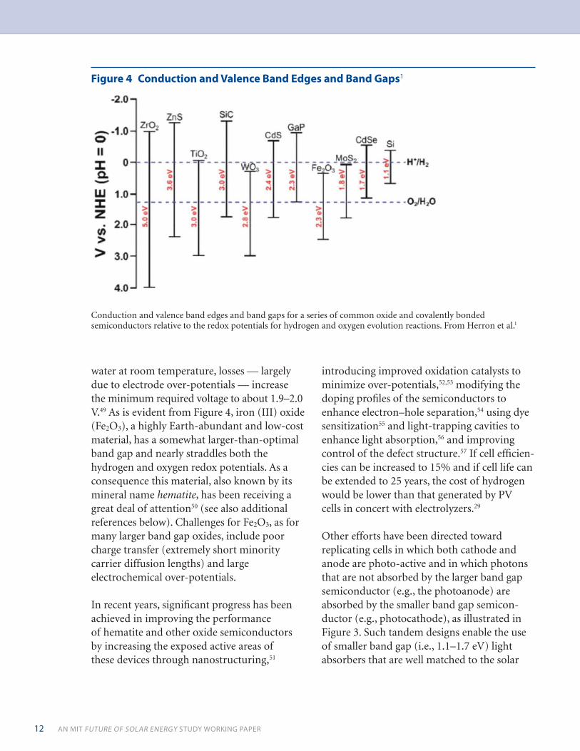
Often the assistance of an external bias or voltage is needed due to the poor alignment of the energy bands in the solid with the redox levels in solution. Figure 4 makes clear why the number of photo-electrode semiconductor candidates is much more restricted than for PV systems. A key criterion for the solar
absorber is that its band gap energy be of such magnitude (~1.4 electron volts (eV)) that it absorbs a signifi cant fraction of the incident infrared and visible sunlight without losses to heat from the absorption of higher energy photons with energies much above the band gap energy. As a photo-electrode, not only must the band gap be of the correct magnitude, but the band edges must straddle the redox potentials for hydrogen and oxygen evolution reactions (see Figure 4). Taking titanium dioxide (TiO2) as an example, its conduction band barely straddles the redox potential for hydrogen evolution and its band gap of 3.0 eV falls in the ultraviolet range of the spectrum, which leaves only several percent of the incident solar radiation that can be absorbed by the material. The result is a solar-to-hydrogen conversion effi ciency of only about 0.4%.48 As in the conventional electrolysis cell, while only 1.23 V is thermo dynamically required to split
Figure 3 A Schematic of a Two Photoelectrode PEC Cell1
A schematic of a two photoelectrode PEC Cell in which the n-type photoanode and p-type photocathode are selected so that the low energy photons not absorbed by the photoanode are absorbed by the photocathode. From Ref. 47.
12 AN MIT FUTURE OF SOLAR ENERGY STUDY WORKING PAPER
water at room temperature, losses — largely due to electrode over-potentials — increase the minimum required voltage to about 1.9–2.0 V.49 As is evident from Figure 4, iron (III) oxide (Fe2O3), a highly Earth-abundant and low-cost material, has a somewhat larger-than-optimal band gap and nearly straddles both the hydrogen and oxygen redox potentials. As a consequence this material, also known by its mineral name hematite, has been receiving a great deal of attention50 (see also additional references below). Challenges for Fe2O3, as for many larger band gap oxides, include poor charge transfer (extremely short minority carrier diffusion lengths) and large electrochemical over-potentials.
In recent years, signifi cant progress has been achieved in improving the performance of hematite and other oxide semiconductors by increasing the exposed active areas of these devices through nanostructuring,51
introducing improved oxidation catalysts to minimize over-potentials,52,53 modifying the doping profi les of the semiconductors to enhance electron–hole separation,54 using dye sensitization55 and light-trapping cavities to enhance light absorption,56 and improving control of the defect structure.57 If cell effi cien-cies can be increased to 15% and if cell life can be extended to 25 years, the cost of hydrogen would be lower than that generated by PV cells in concert with electrolyzers.29
Other efforts have been directed toward replicating cells in which both cathode and anode are photo-active and in which photons that are not absorbed by the larger band gap semiconductor (e.g., the photoanode) are absorbed by the smaller band gap semicon-ductor (e.g., photocathode), as illustrated in Figure 3. Such tandem designs enable the use of smaller band gap (i.e., 1.1–1.7 eV) light absorbers that are well matched to the solar
Figure 4 Conduction and Valence Band Edges and Band Gaps1
Conduction and valence band edges and band gaps for a series of common oxide and covalently bonded semiconductors relative to the redox potentials for hydrogen and oxygen evolution reactions. From Herron et al.1

Solar Alternative Fuels 13
spectrum, while simultaneously providing the necessary photovoltage required to electrolyze water (that is, the voltage exceeds the sum of the thermodynamically required potential [1.23 V], resistive losses, and over-potentials required to drive the water splitting reactions at anode and cathode at a given current density58). The use of a tandem structure also relaxes the cell’s stability requirements, thereby enabling the use of photocathodes that are stable under cathodic (but not necessarily anodic) conditions, and vice versa for the photoanodes.59 In other tandem designs, the oxygen evolution and hydrogen evolution reactions occur at electrocatalysts (e.g., Pt) deposited on and driven by tandem semicon-ducting light absorbers that covert the incident light into a photovoltage.58 Early examples developed at the National Renewable Energy Laboratory (NREL) were composed of a p-type GaInP2 PEC cell connected to a GaAs PV cell and exhibited solar-to-hydrogen conversion effi ciencies of 12%, but they suffered from rapid corrosion.60 More recent results have been obtained for silicon-hematite (Si/Fe2O3) multijunction photoanodes in which Earth-abundant silicon (Si) acts as the photo-absorber and iron oxide acts as the catalyst. Cells of this type have produced current densities as high as 17 mA cm-2.61 A similar arrangement combining a Si photo-absorber with an n-type tungsten trioxide photoanode showed considerably lower current densities, but demonstrated the use of a silicon micro-wire forest electrode array that offers orthogonalization of light absorption and charge-carrier collection.62 As illustrated in Figure 5, light is absorbed along the length of the wires, allowing the use of low cost semiconductors, such as Si, that are character-ized by a more weakly absorbing indirect band gap. At the same time, minority holes in the photoanode or minority electrons in the
photocathode need only diffuse a short distance along the diameter of the wire to reach the solid–liquid interface, thereby enabling the use of easily grown, low-minority carrier diffusion-length materials. Tandem structures, in which Si is paired with 1.6–1.8 eV band gap semiconductors, promise solar-to-hydrogen effi ciencies greater than 25%.58 Key parameters include identifying solar absorbers with high fi ll factors while matched to achieve high photocurrent densities, highly effi cient electrocatalysts, and low electrolyte ohmic resistance.58
Figure 5 Illustration of a PEC Cell
Illustration of a PEC cell with photocathodes and photoanodes in nanowire forest confi guration with the anodic and cathodic chambers separated by a proton permeable membrane. Light capture is enhanced by having the nanowires oriented parallel to the incident radiation, while minority charge carriers need only diffuse short distances along the radii of the wires to reach the solution interface. Copyright © 2010 American Chemical Society.63,64

14 AN MIT FUTURE OF SOLAR ENERGY STUDY WORKING PAPER
2.1.1.2 Solar Thermochemical Hydrogen Production
Solar thermal power, or CSP, is an alternate means of harnessing incident solar energy that can be utilized to generate solar fuels, in addition to its more common use, in which high temperatures generated by concentrating incident solar radiation are used to drive conventional steam or gas turbines.65 This paper discusses several routes to using CSP for solar fuel generation. While thermochemical approaches are particularly promising, progress to date has been largely limited to laboratory demonstrations.
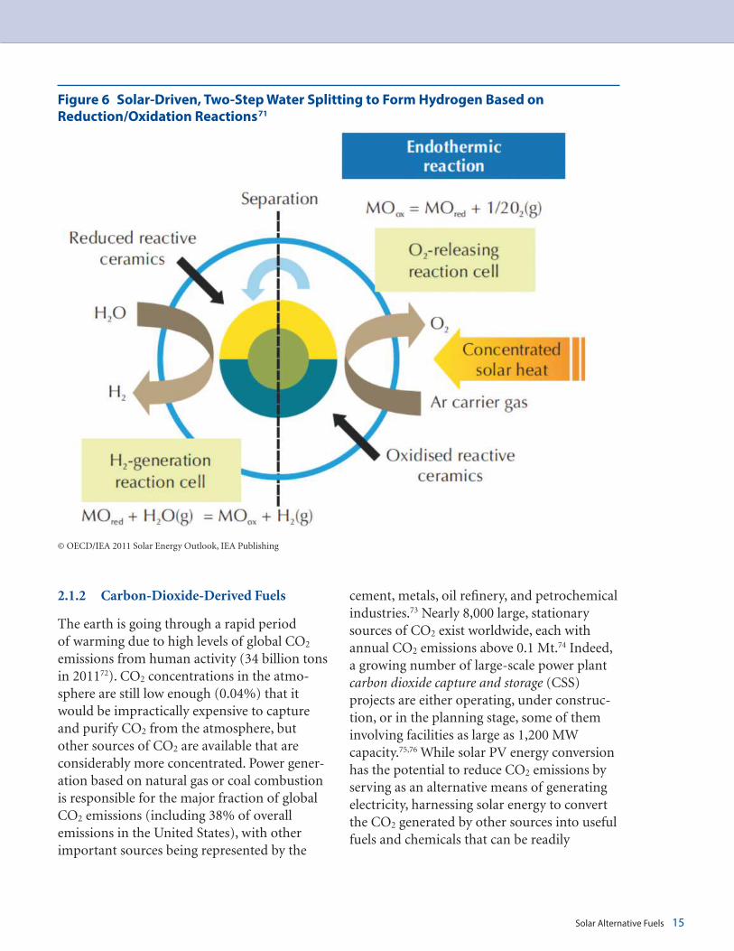
Heating water to suffi ciently high tempera-tures to cause water molecules to split into hydrogen and oxygen or cause methane molecules to split into hydrogen and carbon by solar thermolysis requires temperatures above 2,200°C. This approach is not being actively pursued given the diffi culty of reaching such high temperatures by solar concentration and given the fact that very few containment materials can stand up to these extremes. On the other hand, high-temperature, solar-driven, thermochemical fuel production, based on the ability to induce low-cost metal oxides to release oxygen (i.e., to reduce them) by heating them to high but more moderate temperatures (typically 500°C–1,500°C), with the aid of concentrated solar energy technology, is being investigated. These oxygen-defi cient materials are then subse-quently exposed to water or CO2 at a lower temperature, which allows them to recover their lost oxygen, thereby releasing hydrogen from water or CO from CO2 (see Figure 6). This two-step process eliminates the need
for high temperature gas separation of, for example, the H2 and O2 formed during water thermolysis, and allows coordination with the daily solar cycle (the reduction step can occur during daylight, the reoxidation step during the evening). Alternatively, the two steps can be separated spatially by delivering the deoxidized materials where the hydrogen is needed, e.g., at refueling stations or chemical plants, thereby achieving higher volumetric energy densities than are available with compressed hydrogen. Recent examples of materials that have been studied for solar-driven, thermochemical fuel production include zinc oxide (ZnO) decomposition into Zn metal66 or the reduction of cerium dioxide (CeO2) to its oxygen-defi cient form, CeO2-x.67 Theoretical solar-to-fuel effi ciencies as high as 35%–50% have been estimated, but these assume high rates of fuel production and a high level of heat recovery.68 A recent analysis suggests that a solar-to-methanol system that achieved 7.1% effi ciency with H2O and CO2 as feedstocks would result in methanol’s price being competitive with that of other renewable-resource-based alternatives.69
While the solar thermochemical process provides a clean, effi cient, and sustainable route for producing hydrogen from water, challenges include reducing heat losses during each step of the process cycle, scaling up and improving the coupling of the solar concentra-tors to the reactors,70 identifying appropriate reactor containment materials and seals, and ensuring that the working materials continue to allow for rapid reduction and oxidation during the cycling process even after many thermochemical cycles.
Solar Alternative Fuels 15
2.1.2 Carbon-Dioxide-Derived Fuels
The earth is going through a rapid period of warming due to high levels of global CO2 emissions from human activity (34 billion tons in 201172). CO2 concentrations in the atmo-sphere are still low enough (0.04%) that it would be impractically expensive to capture and purify CO2 from the atmosphere, but other sources of CO2 are available that are considerably more concentrated. Power gener-ation based on natural gas or coal combustion is responsible for the major fraction of global CO2 emissions (including 38% of overall emissions in the United States), with other important sources being represented by the
cement, metals, oil refi nery, and petrochemical industries.73 Nearly 8,000 large, stationary sources of CO2 exist worldwide, each with annual CO2 emissions above 0.1 Mt.74 Indeed, a growing number of large-scale power plant carbon dioxide capture and storage (CSS) projects are either operating, under construc-tion, or in the planning stage, some of them involving facilities as large as 1,200 MW capacity.75,76 While solar PV energy conversion has the potential to reduce CO2 emissions by serving as an alternative means of generating electricity, harnessing solar energy to convert the CO2 generated by other sources into useful fuels and chemicals that can be readily
Figure 6 Solar-Driven, Two-Step Water Splitting to Form Hydrogen Based on Reduction/Oxidation Reactions71
© OECD/IEA 2011 Solar Energy Outlook, IEA Publishing

16 AN MIT FUTURE OF SOLAR ENERGY STUDY WORKING PAPER
integrated into existing storage and distribu-tion systems would move us considerably closer to achieving a carbon-neutral energy environment. This section reviews options for CO2 capture and separation.
Herron et al., in a very recent review, examine the main routes for CO2 capture from stationary sources with high CO2 concentra-tions derived from post-combustion, pre-combustion, and oxy-combustion processes.1 In post-combustion, fl ue gases formed by combustion of fossil fuels in air lead to gas streams with 3%–20% CO2 in nitrogen, oxygen, and water. Other processes that produce even higher CO2 concentrations include pre-combustion in which CO2 is gener-ated at concentrations of 15%–40% at elevated pressure (15–40 bar) during H2 enrichment of synthesis gas (syngas) via a water–gas shift reaction (WGS — see Figure 1) and oxy-combustion in which fuel is combusted in a mixture of O2 and CO2 rather than air, leading to a product with 75%–80% CO2. CO2 capture can be achieved by absorption using liquid solvents (wet-scrubbing) or solid adsorbents. In the former approach, physical solvents (e.g., methanol) are preferred for concentrated CO2 streams with high CO2 partial pressures, while chemical solvents (e.g., monoethanolamine [MEA]) are useful in low-pressure streams. Energy costs for MEA wet-scrubbing are reportedly as low as 0.37–0.51 MWh/ton CO2 with a loading capacity of 0.40 kg CO2 per kg MEA. Disadvantages of this process are the high energy cost for regenerating solvent, the cost to compress captured CO2 for transport and storage, and the low degradation tempera-ture of MEA. Alternatives include membrane and cryogenic separation. With membranes there is an inverse correlation between selectivity and permeability, so one must
optimize between purity and separation rate. Cryogenic separation ensures high purity at the expense of low yield and higher cost. Currently, MEA absorption is industrially practiced, but is limited in scale: 320–800 metric tonsviii CO2/day (versus a CO2 genera-tion rate of 12,000 metric tons per day for a 500 MW power plant). Scale-up would be required to satisfy the needs of a solar refi nery. Alternatives, such as membranes, have rela-tively low capital costs, but require high partial pressures of CO2 and a costly compression step to achieve high selectivity and rates of separation.
While capturing CO2 and converting it to liquid fuels serves society’s greater good, the important question still to be resolved is “what are the incentives for power plants and other industrial sources to pursue this approach?” Indeed, since carbon capture reduces the effi ciency of power generation, power plants with carbon capture will produce more CO2 emissions (per MWh) than a power plant that does not capture CO2. Therefore, the cost of transportation fuel produced with the aid of CO2 capture must also cover the incremental cost of the extra CO2 capture.77 These costs must then be compared to the alternative costs associated with large-scale CO2 sequestration, the practicality of which also remains to be demonstrated. Finally, one also needs to consider the longer-term rationale for converting CO2 to liquid fuels once fossil-fuel power plants cease to be major sources of CO2. Closed-cycle fuel combustion and capture of CO2 from, e.g., vehicle tailpipes, presents a considerably greater technical and cost chal-lenge than capture from concentrated stationary sources.
viii One metric ton (MT) = 1,000 kg.

Solar Alternative Fuels 17
CO2 can be converted to fuels with renewable, solar-derived hydrogen and solar heat, as discussed above. For example, the reverse-water–gas-shift reaction (RWGS)
CO2 + H2 ➞ CO + H2O
can be used, in concert with catalysts (copper-, iron-, or ceria-based systems), to convert CO2 and hydrogen to CO and water. The CO mixed with hydrogen produces syngas, which can be used to generate a variety of products, including methanol, or liquid hydrocarbons through Fischer–Tropsch synthesis.78 Issues related to the thermal stability of the catalysts and the undesired formation of methane still need to be resolved. There are also direct routes for hydrogenating CO2 to make prod-ucts including methanol, methane, and formic acid. Besides these hydrogenation routes, CO2 can also, in principle, be converted to fuels using direct solar energy through electro-catalytic, photo-electrochemical, and thermo-chemical reduction, although these approaches remain in very early stages of development.
2.1.2.1 Electrolysis
CO2 can be electrolytically reduced to fuels in a manner similar to water electrolysis with oxygen evolving at the anode and CO2 reduc-tion occurring at the cathode. The product of the reduction depends on the electro-catalyst used and can include formic acid, formalde-hyde, methanol, methane, or ethylene. Main challenges include high cell over-potentials, low faradaic effi ciency, low current densities, and electrocatalyst deactivation.79 Because the thermodynamic potential for CO2 reduction is similar to that of water splitting (1.23 V), the process results in low faradaic effi ciency, given the competition to generate hydrogen. Only copper is able to reduce CO2 to hydrocarbons (i.e., methane, ethylene) with signifi cant
current densities at moderate over-potentials and reasonable faradaic effi ciency.
More promising is high-temperature CO2 reduction by solid-oxide electrolysis cells (SOEC).43 As discussed above, high-temperature operation decreases the electrical energy required to drive the reaction, while simulta-neously accelerating electrode reaction kinetics. Effi cient reduction of CO2 at 800°C has been achieved with the perovskite oxide electrode La0.8Sr0.2Cr0.5Mn0.5O3 (LSCM) in combination with a Pd–ceria/YSZ co-catalyst. Of particular interest is high-temperature co-electrolysis of H2O and CO2 that produces syngas at the cathode and O2 at the anode. Graves et al. have proposed a CO2-to-fuels process involving co-electrolysis, calculating that the process could operate at 70% elec-tricity-to-liquid-fuels effi ciency.43 While perhaps overly optimistic given the high cost of atmospheric CO2 capture, their fi ndings point to high-temperature co-electrolysis as a technology that is deserving of continued attention. A prototype 40 kW SOEC is to be installed by Haldor Topsoe A/S, a major Danish company noted for its catalysis tech-nology, for the production of synthesis gas as part of project to convert biomass- and wind-generated electricity into synthetic fuels.80
2.1.2.2 Photoelectrochemical and Thermochemical Approaches
Both of these approaches are considerably less developed than the SOEC approach discussed above and are at the stage of early laboratory-scale studies. As with water splitting, the main challenge for the photo-electrochemical approach is to identify suitable photo-cathodes that enable reduction with the aid of visible light irradiation. Other complications include limited solubility of CO2 in aqueous solutions as well as competition from hydrogen

18 AN MIT FUTURE OF SOLAR ENERGY STUDY WORKING PAPER
evolution. Approaches being investigated include the use of non-aqueous solvents81 or the use of three-phase (solid/liquid/vapor) interfaces in which metal-mesh electrodes are partially immersed in solution while CO2 is supplied from the vapor phase.82
The thermochemical reduction of a metal oxide can be followed by re-oxidation with CO2 as the oxidant rather than with water. For example, ZnO can fi rst be reduced to Zn at 1,600°C with the aid of solar heating, then subsequently cooled to 360°C, at which point the Zn can be reacted with CO2 to form ZnO and CO.83 The Zn/ZnO thermochemical cycle has a theoretical maximum solar-to-chemical-energy conversion effi ciency of 39%, but as with thermochemical reduction of water to hydrogen, major losses are associated with poor heat recovery.84 A key drawback of this process is Zn volatility, which requires that Zn vapor be separated from O2. An alternative option is the thermochemical co-reaction of CO2 and H2O with CeO2 to produce CO, H2, and O2. The reaction cycle (repeated 500 times) begins with CeO2 being reduced at 1,420°C –1,640°C, followed by oxidation with CO2 and H2O at 900°C. While theoretical solar-to-fuel effi ciencies as high as 16%–19% have been predicted, only 0.8% effi ciency has been achieved experimentally with heat loss being the main drawback.67
CO2 can be converted to useful products with the aid of hydrogen following recognized industrial processes, i.e., reduction of CO2 to CO using renewable solar hydrogen, syngas production by combining H2 with CO, and direct hydrogenation of CO2 to chemicals and other fuels. The result is a fuel that is easier to store, distribute, and utilize within the present infrastructure, as compared to hydrogen gas. Alternatively, CO2 can be directly reduced to fuel through PV-electrolytic or PEC methods.
When compared to water splitting, however, conversion rates, effi ciencies, and selectivity are low. Considerable work is needed to identify more effi cient processes and catalysts for CO2 reduction by these more direct methods.
3. Key Challenges and Opportunities
To meet increasing energy needs, while limiting greenhouse gas emissions over the next 20 years, an estimated 5–10 TW of energy from renewable sources will be needed. Given the limited ability of non-solar renewable resources (geothermal, wind, hydro, etc.) to supply energy on this scale, it is estimated that in the period 2030–2050, 10%–25% of the world’s energy will need to come from solar energy.20 A high fraction of solar investment will likely be directed to electrical energy generation given that the cost of solar elec-tricity is approaching grid parity, at least in states with high electricity rates. However, since electricity production currently accounts for only about one-third of total primary energy consumption, solar-to fuel conversion will need to play an increasingly important role.
As is evident from the above discussion, hydrogen can be expected to retain its central role as a solar fuel, given its broad utility in fuel cells, its potential role in coping with intermittent renewable generators, and its use as a basic feedstock chemical. However, hydrogen does have drawbacks, at least for the time being, with respect to storage and trans-port. Taking a broader perspective, hydro-carbon fuels that could be derived from direct conversion of CO2 and water by solar means and that are compatible with the existing energy and transportation infrastructure are

Key Challenges and Opportunities 19
highly attractive alternatives. However, the pathway to effi cient, low-cost CO2-derived solar fuels must fi rst overcome many technical challenges. More generally, rapid adoption of alternative energy conversion and storage technologies requires that costs be brought down to competitive levels.
Given the many possible options for reducing CO2 emissions via utilization of solar-assisted hydrogen production it is a useful exercise to consider and rank these opportunities.85 The fi rst option is to use solar H2 to displace steam methane reforming as a means to generate H2 for use in fertilizer production and fuel refi nery operations. This would require only a few percent of current annual global solar PV electricity generation, but it would have a noticeable impact on CO2 emissions. Similarly, solar hydrogen could be used to minimize the extent of water gas shift reactions in coal-to-chemical conversion plants. Fuel cell cars are fi nally reaching the marketplace in 2015; Toyota, Honda, and Hyundai are introducing models and have made commitments to build 100 hydrogen refueling stations in Japan and 48 in southern California by 2016.86,87,88 While these initial commitments represent a rela-tively small volume of hydrogen, gearing up to supply growing demand with solar-derived hydrogen, rather than hydrogen from steam methane reforming, would be a good exercise in developing the needed infrastructure for hydrogen generation, distribution, and storage. More generally, the issues associated with hydrocarbon-based transportation fuels are diffi cult to address with a carbon-neutral solution, as discussed above, until power plant operators face incentives to capture CO2 and convert it to fuels. In the short term, one could consider thermochemical pathways for gener-ating more fuel per ton of biomass via pyrol-ysis and gasifi cation pathways, both of which require hydrogen that solar could provide.
If solar fuels are to have a major impact on the energy supply mix in the long term, substantial research funding is needed to support innova-tions in the materials and technologies that underpin the solar refi nery concept for deliv-ering solar fuels. To identify promising tech-nologies that warrant further research and development, it is useful to refer back to Table 1 prepared by Herron et al.1 Outside the thermochemical approach, a common theme in solar fuels production is the use of electro-chemical cells, where the driving source is either solar electricity or direct photo-generated electrical current, as in photo-electrochemical cells. In general, the most critical opportunities for improvement are in (photo)electrocatalysts — specifi cally, improving effi ciency (lower over-potentials), lowering costs (reduced use of noble metals), and extending life. Among commercial-scale electrolyzers, the PEM electrolyzer shows particular promise as the power plant when run in fuel cell mode in vehicles or as the companion to PV cells to generate hydrogen in the electrolysis mode. R&D funds directed toward identifying less costly and higher-temperature operating polymer electrolyte membranes, as well as less costly and longer-lived oxygen evolution catalysts, would both promote solar hydrogen production and solar energy storage by enabling integrated PV–hydrogen utility energy systems as illustrated in Figure 2, as well as hydrogen use in fuel cell vehicles. Another technology that is currently less advanced, but that promises even higher effi ciencies and the ability to co-electrolyze water and CO2 without the need for noble catalysts, is the solid oxide electrolysis cell (SOEC). Key limitations of the SOEC, which can also operate in reverse as a fuel cell, include its use of more costly refractory materials and its potential for more rapid degradation at elevated operating temperatures. Research to improve the electro-catalytic behavior of anodes for oxygen

20 AN MIT FUTURE OF SOLAR ENERGY STUDY WORKING PAPER
evolution should lead to better electricity-to-hydrogen conversion effi ciency and extended life at higher current densities/higher hydrogen evolution fl uxes.
PEC cells, because they combine the separate functions of PV and electrolysis cells into a single cell, offer many potential advantages including higher effi ciency, simplifi ed assembly, and lower-cost materials. However, the more complex criteria that PEC photoelec-trodes must satisfy (e.g., effi cient light absorp-tion and charge transfer, chemical stability, and low cost) translate into greater challenges in fi nding optimized materials. Computational materials science89 can to be applied to screen the enormous numbers of potential candidate materials, together with high-throughput combinatorial fabrication methods,90 promises to rapidly identify promising alternatives. As in the PV fi eld, tandem confi gurations offer potential for absorbing a greater fraction of incident radiation while also driving anodic and cathodic reactions at higher potentials. This would further enhance effi ciency.58 These and other efforts directed to prototyping and scale-up are very much needed and are being pursued, for example, at the Caltech Joint Center for Artifi cial Photosynthesis,91 at NREL,92 and at the University of North Carolina Energy Frontier Research Center for Solar Fuels.93
Synthetic solar-derived hydrocarbon commod-ities, such as methane, methanol, and ethanol are essential for satisfying the need to replace fossil fuels in transportation, heating, and energy storage and as a source of feedstocks for the chemicals, pharmaceutical, and fertil-izer industries. Present technologies for capturing CO2 from fl ue gases (e.g., gas absorption into solvents or onto sorbents, membrane permeation, or cryogenic distilla-tion) remain costly and impose signifi cant energy penalties for CO2 stripping and sorbent
regeneration. Identifying membranes with high selectivity and permeability remains a great challenge. Photocatalytic processes capable of removing CO2 and simultaneously converting it to marketable hydrocarbon products deserve attention.94
The use of solar thermal power, or CSP, to drive high-temperature thermochemical reactors, offers potential for achieving high solar-to-fuel energy conversion effi ciencies and competitive costs in the short-to-intermediate term. Efforts to identify effective materials, coupled with the optimum combination of desirable thermo-dynamic, kinetic, and stability traits, would benefi t as well from the application of compu-tational materials science tools that are capable of comparing thousands of materials couples in short order. Scaling solar reactors and reducing heat losses are essential to achieving effi cient, long-lived, and cost-effective systems.
In summary, harnessing solar energy to produce solar fuels offers, over the long run, the opportunity to replace fossil fuels as the major source of energy and commodity chemicals while also providing a means for storing energy from the essential but inher-ently intermittent solar resource. To become competitive in the marketplace, the local and effi cient collection of CO2 from power plants or other sources and the low-cost production of H2 from water by photo-assisted electrolysis or by thermochemical means must simultaneously be established. This will require concerted research and development efforts in a number of key areas including photovoltaics, elec-trolysis and fuel cells, catalysts, effi cient CO2 collection, hydrogen storage and distribution, and synthetic fuel production from CO and H2 feedstocks. Only a joint and concerted effort by government, industry and academia will lead to measurable progress in this critical endeavor.

Acknowledgments 21
4. Acknowledgments
This report was prepared at the encourage-ment of the organizers and participants of the MIT The Future of Solar Energy study. The careful reading and thoughtful suggestions by Professor Richard Schmalensee of the MIT Sloan School of Management is highly appre-ciated. The author thanks the U.S. Department of Energy, Basic Energy Sciences, for supporting his research on alternative energy generation and storage under award DE SC0002633 and to the Skoltech Center for Electrochemical Energy Storage at MIT. Thanks also go to the International Institute of Carbon Neutral Energy Research (I2CNER), Kyushu University, for its hospitality and support.

22 AN MIT FUTURE OF SOLAR ENERGY STUDY WORKING PAPER
Notes 1 Herron, J.A., J. Kim, A.A. Upadhye, G.W. Huber, C.T. Maravelias. “A General Framework for the Assessment of Solar Fuel Technologies.” Energy Environ. Sci. (2015). 8, 126-157.
2 Williams, J. H., A. DeBenedictis, R. Ghanadan, A. Mahone, J. Moore, W.R. Morrow III, S. Price, and M.S. Torn. “The Technology Path to Deep Greenhouse Gas Emissions Cuts by 2050: The Pivotal Role of Electricity.” Science 335, No. 6064 (2012). 53-59. http://www.sciencemag.org/content/335/6064/53.full
3 Blueprint for a Secure Energy Future. White House Memorandum (March 30, 2011). http://www.whitehouse.gov/sites/default/fi les/blueprint_secure_energy_future.pdf
4 Pandit, A., A. Holzwarth, and H.J.M. de Groot. “Harnessing Solar Energy for the Production of Clean Fuel.” European Science Foundation. (October 10, 2008). https://openaccess.leidenuniv.nl/bitstream/handle/1887/13349/CleanSolarFuel_01.pdf?sequence=1
5 http://www.rita.dot.gov/bts/sites/rita.dot.gov.bts/fi les/publications/pocket_guide_to_transportation/2015/2_Moving_People/table2_1
6 http://www.eia.gov/forecasts/aeo/section_issues.cfm#veh_demand
7 http://www.rita.dot.gov/bts/sites/rita.dot.gov.bts/fi les/publications/national_transportation_statistics/html/table_01_11.html
8 http://www.rita.dot.gov/bts/sites/rita.dot.gov.bts/fi les/publications/national_transportation_statistics/html/table_01_19.html
9 Lewis, N.S. and G. Crabtree. Basis Research Needs for Solar Energy Utilization, Report on the Basic Energy Sciences Workshop on Solar Energy Utilization: April 18-21, 2005. United States Department of Energy. http://science.energy.gov/~/media/bes/pdf/reports/fi les/seu_rpt_print.pdf
10 Bensaid, S., G. Centi, E. Garrone, S. Perathoner, and G. Saracco. “Towards Artifi cial Leaves for Solar Hydrogen and Fuels from Carbon Dioxide.” ChemSusChem 5, No. 3 (2012). 500-521. http://onlinelibrary.wiley.com/doi/10.1002/cssc.201100661/full
11 Berger, B. Electricity Production from Solar and Wind in Germany in 2013. Fraunhofer Institute for Solar Energy Systems. http://www.ise.fraunhofer.de/en/downloads-englisch/pdf-fi les-englisch/news/electricity-production-from-solar-and-wind-in-germany-in-2013.pdf
12 “German Power Sector 27 Percent Non-hydro Renewable in 2014,” http://www.renewablesinternational.net/german-power-sector-27-percent-non-hydro-renewable-in-2014/150/537/80072/
13 Dempsey, J. “Panel Urges Germany to Close Nuclear Plants by 2021.” The New York Times (May 11, 2011). http://www.nytimes.com/2011/05/12/business/energy-environment/12energy.html?_r=0
14 http://www.eia.gov/tools/faqs/faq.cfm?id=427&t=3
15 Rodriguez, C.A., M.A. Modestino, D. Psaltis, and C. Moser. “Design and Cost Considerations for Practical Solar Hydrogen Generators.” Energy Environ. Sci., 7 (2014). 3828-3835.
16 http://www.eia.gov/forecasts/steo/report/renew_co2.cfm
17 Newman, J., P. G. Hoertz, C. A. Bonino, and J. A. Trainham. “Review: An Economic Perspective on Liquid Solar Fuels.” Journal of the Electrochemical Society 159, No. 10 (2012). A1722-A1729. http://jes.ecsdl.org/content/159/10/A1722.full.pdf+html
18 Buck, C. “Second Wind for Hydrogen.” in Siemens Pictures of the Future Magazine. (Spring 2011). 26-28. http://www.siemens.com/innovation/apps/pof_microsite/_pof-spring-2011/_html_en/electrolysis.html
19 Pellow, M. A.. Emmott, C. J. M., Barnhart, C. J. and S.M. Benson. “Hydrogen Or Batteries For Grid Storage? A Net Energy Analysis.” Energy Environ. Sci., 2015 on line, DOI: 10.1039/c4ee04041d
20 “Storing Green Electricity as Natural Gas,” http://www.sciencedaily.com/releases/2010/05/100505113227.htm

Notes 23
21 Solar Fuels and Artifi cial Photosynthesis: Science and Innovation to Change Our Future Energy Options. Royal Society of Chemistry. (January 2012). http://www.rsc.org/images/Solar-fuels_tcm18-221433.pdf
22 Second Report to Congress: Highlights of the Diesel Emissions Reduction Program. United States Environmental Protection Agency. EPA-420-R-12-031. (December 2012). 9. http://www.epa.gov/cleandiesel/documents/420r12031.pdf
23 Global transport scenarios 2050. World Energy Council. (2011). http://www.worldenergy.org/wp-content/uploads/2012/09/wec_transport_scenarios_2050.pdf
24 Lewis, N.S., and D.G. Nocera. “Powering the Planet: Chemical Challenges in Solar Energy Utilization.” Proc Natl Acad Sci USA, 103 (2006). 15729–15735.
25 Kondratenko, E.V., G. Mul, J. Baltrusaitis, G.O. Larrazabal, and J. Perez-Ramirez. “Status and Perspectives of CO2 Conversion Into Fuels and Chemicals by Catalytic, Photocatalytic and Electrocatalytic Processes.” Energy & Environmental Science 6, (2013). 3112-3135. http://pubs.rsc.org/en/content/articlepdf/2013/ee/c3ee41272e
26 Jooss, C. and H. Tributch. “Chapter 47: Solar Fuels” Fundamentals of Materials for Energy and Environmental Sustainability. D.S. Ginley and D. Cahen, editors. Cambridge University Press. (2011). http://cds.cern.ch/record/1613941
27 mitei.mit.edu/futureofsolar
28 Utility Solar Market Snapshot, June 12, 2014, Solar Electric Power Institute. http://www.solarelectricpower.org/
29 International Energy Statistics, U.S. Energy Information Administration. http://www.eia.gov/cfapps/ipdbproject/IEDIndex3.cfm?tid=2&pid=2&aid=7#
30 Pagliaro, M. and A. G. Konstandopoulos. “Chapter 1: Hydrogen and Solar Hydrogen.” Solar Hydrogen: Fuel of the Future. Royal Society of Chemistry. (2012). 1-39.
31 U.S. Department of Energy, Energy Effi ciency & Renewable Energy, Fuel Cell Technologies Offi ce, Multi-Year Research, Development and Demonstration Plan, available at http://energy.gov/eere/fuelcells/downloads/fuel-cell-technologies-offi ce-multi-year-research-development-and-22
32 Barbir, F., “PEM Electrolysis for Production of Hydrogen from Renewable Energy Sources.” Solar Energy 78, (2005). 661-669.
33 Dufoura, J., D.P. Serrano, J.L. Gálvez, J. Moreno, and C. Garcia, “Life Cycle Assessment of Processes for Hydrogen Production: Environmental Feasibility and Reduction of Greenhouse Gases Emissions.” Int. J. Hydrogen Energy 34 (2009). 1370–1376.
34 Pagliaro, M. and A. G. Konstandopoulos. “Chapter 1: Hydrogen and Solar Hydrogen.” Solar Hydrogen: Fuel of the Future. Royal Society of Chemistry. (2012). 40-81.
35 Report of the Hydrogen Production Expert Panel: A Subcommittee of the Hydrogen & Fuel Cell Technical Advisory Committee, U.S. Department of Energy, May 2013. Available Feb. 16, 2015 on http://www.google.com/url?sa=t&rct=j&q=&esrc=s&source=web&cd=1&ved=0CCUQFjAA&url=http%3A%2F%2Fwww.hydrogen.energy.gov%2Fpdfs%2Fhpep_report_2013.pdf&ei=6BXiVNbBLsK7ggTYoIKoBg&usg=AFQjCNH4vcCh_TfvGr9H257qxwFcBMS1uA&bvm=bv.85970519,d.eXY
36 M Pagliaro, M. and A. G. Konstandopoulos. “ Chapter 2: Water Electrolysis with Solar Electricity.” Solar Hydrogen: Fuel of the Future. Royal Society of Chemistry. (2012). 40-81.
37 Holladay, J.D., J. Hu, D.L. King, Y. Wang. “An Overview of Hydrogen Production Technologies,” Catalysis Today 139 (2009). 244–260.
38 Gibson T. L. and N.A. Kelly. “Optimization of Solar Powered Hydrogen Production using Photovoltaic Electrolysis Devices.” Int. J. Hydrogen Energy. (2008). 33, 5931–5940.
39 Hu, S., C. Xiang, S. Haussener, A.D. Berger, N.S. and Lewis. “An Analysis of the Optimal Band Gaps of Light Absorbers in Integrated Tandem Photoelectrochemical Water-Splitting Systems.” Energy Environ. Sci., 6, (2013). 2984-2993.
40 Shaner, M,R., S. Hu, K. Sun, and N.S. Lewis. “Stabilization of Si Microwire Arrays for Solar-driven H2O Oxidation to O2(g) in 1.0 M KOH(aq) using Conformal Coatings of Amorphous TiO2”. Energy Environ. Sci., 8, (2015). 203-207.

24 AN MIT FUTURE OF SOLAR ENERGY STUDY WORKING PAPER
41 Maeda, K., and K. Domen. “Photocatalytic Water Splitting: Recent Progress and Future Challenges.” J. Phys. Chem. Lett. 1, (2010). 2655–2661.
42 Warren, E. L., H.A. Atwater, and N.S. Lewis. “Silicon Microwire Arrays for Solar Energy-Conversion Applications.” J. Phys. Chem. C 118 (2014). 747−759.
43 Graves, C., S.B. Ebbesen, M. Mogensen, and K.S. Lackner. “Sustainable Hydrocarbon Fuels by Recycling CO2 and H2O with Renewable or Nuclear Energy.” Renewable and Sustainable Energy Reviews 15 (2011). 1–23.
44 Khaselev, O., A. Bansal, and J.A. Turner. “High-effi ciency Integrated Multijunction Photovoltaic/Electrolysis Systems for Hydrogen Production.” Int. J. Hydrogen Energy. (2001). 26, 127-132.
45 Barbir, F., M. Lillis, F. Mitlitsky, and T. Molter, 2002. Regenerative Fuel Cell Applications and Design Options. In: Proc. 14th World Hydrogen Energy Conference, Montreal, Canada. As referenced in Ref. 35.
46 Rodriguez, C.A., M.A. Modestino, D. Psaltis, and C. Moser. “Design and Cost Considerations for Practical Solar Hydrogen Generators.” Energy Environ. Sci., 7 (2014). 3828-3835.
47 Jianwei Sun, J., D.K. Zhong, and D.R. Gamelin. “Composite Photoanodes for Photoelectrochemical Solar Water Splitting.” Energy Environ. Sci., 3, (2010). 1252–1261.
48 Bak, T., J. Nowotny, M. Rekas, and C.C. Sorrell. “Photo-electrochemical Hydrogen Generation from Water using Solar Energy. Materials-related aspects.” Int. J. Hydrogen Energy, 27 (2002). 991–1022.
49 Van de Krol, R., Y. Liang, and J. Schoonman. “Solar Hydrogen Production with Nanostructured Metal Oxides.” J. Mater. Chem., 18 (2008). 2311–2320.
50 Kronawitter, C.X., I. Zegkinoglou, S.-H. Shen, P. Liao, I. S. Cho, O. Zandi, Y.-S. Liu, K. Lashgari, G. Westin, J.-H. Guo, F. J. Himpsel, E. A. Carter, X. L. Zheng T. W. Hamann, B. E. Koel, S. S. Mao and L. Vayssieres, “Titanium Incorporation into Hematite Photoelectrodes: Theoretical Considerations and Experimental Observations.” Energy Environ. Sci., 2014, 7. 3100-3121.
51 Warren, S. C., K. Voïtchovsky, H. Dotan, C. M. Leroy, M. Cornuz, F. Stellacci, C. Hébert, A. Rothschild and M. Grätzel, “Identifying Champion Nanostructures for Solar Water-Splitting.” Nature Materials 12, No. 9. (2013). 842-849. http://www.nature.com/nmat/journal/v12/n9/full/nmat3684.html
52 Kanan, M.W. and D. G. Nocera. “In Situ Formation of an Oxygen-Evolving Catalyst in Neutral Water Containing Phosphate and Co2+,” Science (2008). 321, 1072–1075.
53 Sun, J., D.K. Diane Zhong, and D.R. Gamelin. “Composite Photoanodes for Photoelectrochemical Solar Water Splitting.” Energy Environ. Sci., 3 (2010). 1252–1261.
54 Abdi, F. F., L. Han, A.H.M. Smets, M. Zeman, B. Dam and R. van de Krol. “Effi cient Solar Water Splitting by Enhanced Charge Separation in a Bismuth Vanadate-Silicon Tandem Photoelectrode.” Nature Communications 4 (2013). 2195. http://www.nature.com/ncomms/2013/130729/ncomms3195/pdf/ncomms3195.pdf
55 Kumar, M. H., N. Mathews, P.P. Boix, K. Nonomura, S. Powar, L.Y. Ming, M. Graetzel, and S.G. Mhaisaklar. “Decoupling Light Absorption and Charge Transport Properties in Near IR-sensitized Fe2O3 Regenerative Cells.” Energy & Environmental Science 6, No. 11 (2013). 3280-3285. http://pubs.rsc.org/en/content/articlepdf/2013/EE/C3EE42438C
56 Dotan, H., O. Kfi r, E. Sharlin, O. Blank, M. Gross, I. Dumchin, G. Ankonina, and A. Rothschild. “Resonant Light Trapping in Ultrathin Films for Water Splitting.” Nature Materials 12, No. 2. (2013). 158-164. http://www.nature.com/nmat/journal/v12/n2/pdf/nmat3477.pdf
57 Engel, J., and H. L. Tuller. The Electrical Conductivity of Thin Film Donor Doped Hematite: From Insulator to Semiconductor by Defect Modulation, Phys. Chem. Chem. Phys., 16. (2014). 11374-11380.
58 Hu, S., C. Xiang, S. Haussener, A.D. Berger, and N.S. Lewis. “An Analysis of the Optimal Band Gaps of Light Absorbers in Integrated Tandem Photoelectrochemical Water-splitting Systems.” Energy Environ. Sci. (2013). 6, 2984, 2993.
59 Boettcher, S.W., E.L. Warren, M.C. Putnam, E.A. Santori, D. Turner-Evans, M.D. Kelzenberg, M.G. Walter, J.R. McKone, B.S. Brunschwig, H.A. Atwater, and N.S. Lewis. “Photoelectrochemical Hydrogen Evolution Using Si Microwire Arrays.” J. Am. Chem. Soc. (2011). 133, 1216–1219.

Notes 25
60 Khaselev, O., J.A. Turner. “A Monolithic Photovoltaic-photoelectrochemical Device for Hydrogen Production via Water Splitting.” Science 1998 280, 425-427.
61 Jun, K., Y.S. Lee, T. Buonassisi, and J.M. Jacobson. “High Photocurrent in Silicon Photoanodes Catalyzed by Iron Oxide Thin Films for Water Oxidation.” Angew. Chem. Int. Ed. 2012, 51, 423–427.
62 Shaner, M. R., K.T. Fountaine, S. Ardo, R.H. Coridan, H.A. Atwater, and N.S. Lewis. “Photoelectrochemistry of Core–shell Tandem Junction n–p+-Si/n-WO3 microwire array photoelectrodes.” Energy Environ. Sci., 7. (2014). 779-790.
63 Warren, E. L., H.A. Atwater, and N.S. Lewis. “Silicon Microwire Arrays for Solar Energy-Conversion Applications.” J. Phys. Chem. C 118 (2014). 747−759.
64 http://nsl.caltech.edu/research
65 Mehos, M., “Another Pathway to Large-Scale Power Generation: Concentrating Solar Power.” MRS Bulletin, 33 (2008): 364-366.
66 Steinfeld, A. “Solar Hydrogen Production via a Two-step Water-splitting Thermochemical Cycle Based on Zn/ZnO Redox Reactions.” International Journal of Hydrogen Energy 27, No. 6 (2002). 611-619. http://dx.doi.org/10.1016/S0360-3199(01)00177-X
67 Chueh, W. C., C. Falter, M. Abbott, D. Scipio, P. Furier, S.M. Haile, and A. Steinfeld. “High-fl ux Solar-driven Thermochemical Dissociation of CO2 and H2O Using Nonstoichiometric Ceria.” Science 330, No. 6012 (2010). 1797-1801. http://www.sciencemag.org/content/330/6012/1797.full.pdf
68 Smestad, G.P., and A. Steinfeld. Review: Photochemical and Thermochemical Production of Solar Fuels from H2O and CO2 using Metal Oxide Catalysts. Ind. Eng. Chem. Res. 51, (2012) 11828-11840.
69 Kim, J. et al. “Methanol Production from CO2 Using Solar-thermal Energy: Process Development and Techno-economic Analysis.” Energy & Environmental Science 4, No. 9. (2011). 3122-3132. http://pubs.rsc.org/en/content/articlepdf/2011/EE/C1EE01311D
70 Perret, R. Solar Thermochemical Hydrogen Production Research (STHC): Thermochemical Cycle Selection and Investment Priority. Sandia National Laboratories. Technical Report SAND2011-3622, (May 2011). https://www1.eere.energy.gov/hydrogenandfuelcells/pdfs/solar_thermo_h2.pdf
71 Philibert, C. Solar Energy Perspectives. International Energy Agency. (2011). 166. Source: Tamaura, Kaneko et al. Solutions Research Laboratory, Tokyo Institute of Technology. http://www.iea.org/publications/freepublications/publication/Solar_Energy_Perspectives2011.pdf
72 Espinal, L., D.L. Poster, W. Wong-Ng, A.J. Allen, and M.L. Green. “Measurement, Standards, and Data Needs for CO2 Capture Materials: A Critical Review” Environ. Sci. Technol., 47 (2013). 11960–11975. http://www.iea.org/t&c/termsandconditions/
73 Carbon Dioxide Emissions. United States Environmental Protection Agency. http://www.epa.gov/climatechange/ghgemissions/gases/co2.html
74 Metz, B., O. Davidson, H. C. De Coninck, M. Loos, and L. A. Meyer. “IPCC Special Report on Carbon Dioxide Capture and Storage: Prepared by Working Group III of the Intergovernmental Panel on Climate Change.” Cambridge University Press. (2005). http://www.langtoninfo.com/web_content/9780521685511_frontmatter.pdf
75 http://www.globalccsinstitute.com/projects/large-scale-ccs-projects
76 http://sequestration.mit.edu/tools/projects/index.html
77 Randall Field, MIT Energy Initiative, personal communications.
78 Daza, Y. A., R.A. Kent, M.M. Yung, and J.N. Kuhn. “Carbon Dioxide Conversion by Reverse Water−Gas Shift Chemical Looping on Perovskite-Type Oxides” Ind. Eng. Chem. Res. 53 (2014). 5828−5837.
79 Spinner. N. S., J. A. Vega and W. E. Mustain. “Recent Progress in the Electrochemical Conversion and Utilization of CO2”. Catal. Sci. Technol., (2012). 2, 19–28.
80 Skovse, K.H. “DTU and Haldor Topsoe A/S Signs New Electrolysis Agreement.” available at http://www.dtu.dk/english/News/Nyhed?id=2f255211-594f-47c9-9f5d-fe5cc4cb8048

81 Kumar, B., M. Llorente, J. Froehlich, T. Dang, A. Sathrum, and C.P. Kubiak. “Photochemical and Photoelectrochemical Reduction of CO2” Annu. Rev. Phys. Chem., 63 (2012). 541–569.
82 Ogura, K., “Electrochemical Reduction of Carbon Dioxide to Ethylene: Mechanistic approach.” Journal of CO2 Utilization, 2013, 1, 43–49.
83 Abanades, S., and M. Chambon. “CO2 Dissociation and Upgrading from Two-Step Solar Thermochemical Processes Based on ZnO/Zn and SnO2/SnO Redox Pairs.” Energy Fuels, 24 (2010). 6667–6674.
84 Galvez, M. E., P.G. Loutzenhiser, I. Hischier, and A. Steinfeld. “CO2 Splitting via Two-Step Solar Thermochemical Cycles with Zn/ZnO and FeO/Fe3O4 Redox Reactions: Thermodynamic Analysis.” Energy Fuels, 22 (2008). 3544–3550.
85 Randall Field, MIT Energy Initiative, personal communications regarding rankings of opportunities.
86 Patnaik, S. Honda, Toyota to Roll Out Fuel-cell cars in 2015: Nikkei, Reuters, March 25, 2014. Available at http://www.reuters.com/article/2014/03/25/us-honda-motor-fuelcells-idUSBREA2O1PR20140325
87 Della Cava, M. “Toyota Quietly Rolls 2015 Fuel Cell Car into Town,” USA Today (Sep 17, 2014). Available at http://www.usatoday.com/story/money/cars/2014/09/17/toyota-2015-fcv-hydrogen-powered-car/15744945/
88 Iwata, M., “Construction of Japanense Hydrogen Refueling Stations Begins,” Wall Street Journal (Sept. 1, 2014). Available at http://www.wsj.com/articles/construction-of-japanese-hydrogen-refueling-station-begins-1409570814
89 Jain, A., S.P. Ong, G. Hautier, W. Chen, W.D. Richards, S. Dacek, S. Cholia, D. Gunter, D. Skinner, G. Ceder, and K.A. Persson. “Commentary: The Materials Project: A Materials Genome Approach to Accelerating Materials Innovation.” APL Materials 1, 011002, 1-11. (2013).
90 Potyrailo, R., K. Rajan, K. Stoewe, I. Takeuchi, B. Chisholm, and H. Lam. “Combinatorial and High-Throughput Screening of Materials Libraries: Review of State of the Art.” ACS Comb. Sci. (2011). 13, 579–633.
91 http://solarfuelshub.org/about/
92 http://www.nrel.gov/hydrogen/
93 http://www.efrc.unc.edu/
94 Usubharatana, P., D. McMartin, A. Veawab, and P. Tontiwachwuthikul. “Photocatalytic Process for CO2 Emission Reduction from Industrial Flue Gas Streams” Ind. Eng. Chem. Res. (2006). 45, 2558-2568.
26 AN MIT FUTURE OF SOLAR ENERGY STUDY WORKING PAPER

Massachusetts Institute ofTechnology