Embed Size (px)
Citation preview
Engineering, 2012, 4, 881-893 http://dx.doi.org/10.4236/eng.2012.412112 Published Online December 2012 (http://www.SciRP.org/journal/eng)
Solar Thermal Systems Performances versus Flat Plate Solar Collectors Connected in Series
Khaled Zelzouli*, Amenallah Guizani, Ramzi Sebai, Chakib Kerkeni Thermal Processes Laboratory (LPT), Research and Technology Center of Energy (CRTEn), Borj Cedria, Tunisia
Email: [email protected]
Received September 26, 2012; revised October 24, 2012; accepted November 7, 2012
ABSTRACT
This paper shows the modeling of a solar collective heating system in order to predict the system performances. Two systems are proposed: 1) the first, Solar Direct Hot Water, which is composed of flat plate collectors and thermal stor- age tank, 2) the second, a Solar Indirect Hot Water in which we added an external heat exchanger of constant effec- tiveness to the first system. The mass flow rate by a collector is fixed to 0.04 Kg·s–1 and the total number of collectors is adjusted to 60. For the first system, the maximum average water temperature within the tank in a typical day in summer and annual performances are calculated by varying the number of collectors connected in series. For the second, this pa- per shows the detailed analysis of water temperature within the storage and annual performances by varying the mass flow rate on the cold side of the heat exchanger and the number of collectors in series on the hot side. It is shown that the stratification within the storage is strongly influenced by mass flow rate and the connections between collectors. It is also demonstrated that the number of collectors that can be connected in series is limited. The optimization of the mass flow rate on cold side of the heat exchanger is seen to be an important factor for the energy saving. Keywords: Thermal Energy; Flat Plate Collectors; Stratification; Solar Heating Systems
1. Introduction
Hot water production is one of the most interesting ap- plications in solar energy and the demand for hot water greatly increases particularly in the residential use. Prin- cipal components of solar hot water systems are solar collectors and thermal storage tank. The storage tank plays an important role in solar energy system by storing energy when it is available and delivering it when it is needed. The performances of solar heating systems are strongly influenced by thermal stratification. Since 1970s, stratification within the storage tank has been intensively studied [1-3] and the low flow rate thermally stratified storage tanks have shown to deliver up to 17% more so- lar energy to the load [4-8]. These authors noted that the thermal stratification has the advantage of increasing the solar water heating system performances. Cristofari et al. [9] have found that with a high degree of stratification, sa- ving energy is higher (5.25% over one year of use) than a fully mixed storage tank. However, a hotter storage tank temperature is designed to meet the energy demand. The degree of thermal stratification, defined as the tempera- ture difference between the top and bottom sections of the tank, is very important for efficient operation of solar energy systems.
The thermal storage tank performance is influenced by many parameters as the tank geometry [10-13], the tank volume and collector area [14-17]; hence many solutions have been proposed and a number of models are devel- oped. Among the most popular models is the one-dimen- sional model [8,18] which provides good estimates of the temperature distribution in the tank. When dealing with the thermal stratification, the primary and essential ele- ment which influences the performance of the system is the mass flow rate from hot source (solar collectors) or/ and load. For the direct-coupled systems (SDHW), it is assumed that the mass flow rate entering storage tank is the same flow rate outlet from collectors.
In the collective use, we use a number of collectors which are fixed in a position in order to get an optimized capture over a year. Solar collectors may be connected together in series or in parallel or in parallel-series. De- spite the fact that parallel connection is preferred by sev- eral users, it causes however some problems such as heat losses and pressure drop. The connections in series or in series-parallel are used in many countries in case the sys- tem is optimized and the influence of the fluid distribu- tions must be taken into account [19,20]. When collectors are mounted in series, mass flow rate is assumed to be the same in each collector and the outlet water tempera- ture increases from a collector to the another. This leads *Corresponding author.
Copyright © 2012 SciRes. ENG
K. ZELZOULI ET AL. 882
to increase of the thermal losses due to the increase of the difference between the inlet and outlet temperature of the collector. Luminosu and Fara [21] and Atkins et al. [22] have shown that the energy efficiency decreases conti- nuously when increasing the collecting surface by con- necting in series of the solar flat plate collectors. For par- allel connections between collectors or arrays of collec- tors, the total mass flow rate returning from the storage tank is divided into several flows and the outlet water temperatures are similar when the collectors are identical. In his study, Garg [23] have shown that the true parallel arrangement of absorber banks yields the maximum of efficiency and economy. Morrison [24] mentioned that using collectors in series, parallel or series-parallel de- pends on the hydraulic design considerations of mini- mum pressure drop and on the equal division between all collectors in the array. Kalogirou [25] noted that the col- lectors’ field should be built from identical modules of series or parallel or series-parallel collectors. He has also noted that modules must be connected in a reverse-return to ensure a self- balanced array since all collectors oper- ate with the same pressure drop. Dubey and Tiwari [26] have studied the analysis of PV/T flat plate water collec- tors connected in series. They showed that the number of series collectors is influenced by mass flow rates.
In the residential use, there are generally two systems for heating water. The first one is the direct-coupled sys- tems (SDHW) which has two ways to circulate the fluid between the collectors and the thermal storage tank, ei- ther by fixing the total mass flow rate returned from the storage tank to the collectors’ field or by fixing the mass flow rate by a collector. Mass flow rate by collector and the total mass flow rate depend on the connection-type between solar collectors. The parallel arrangements be- tween collectors increases the total flow rate entering the storage tank that destroys the stratification and decreases the average water temperature within the storage; and in this case series-parallel combinations are preferred.
The second system is the indirect-coupled system (SI- HW). In this situation, an external heat exchanger is in- stalled between the solar collectors and the storage tank and generally a solution of glycol-water Cp: 3.2 - 4.0 kJ/kg·˚C is used as a collector fluid to avoid freezing problems. A heat exchanger in a solar system, in a given time, gives only a part of energy in the secondary circuit (heat exchanger-storage tank) which causes an increase of fluid temperature in the solar collectors and leads to a lower overall efficiency. The system performances de- pend on the heat transferred from the collectors to the storage tank and this transfer depends itself on the mass flow rates and water temperatures on both sides of the heat exchanger. Good performances can be obtained by optimizing the flow rate on both sides of the heat ex- changer [27]; and the solar fraction is enhanced with an increase in the heat exchanger effectiveness up to values
around 0.7 - 0.8 [12]. The mass flow rate circulates be- tween the heat exchanger and the storage tank either by circulating pump or by natural circulation. Stratification with external heat exchanger was studied intensively [12, 13,16,28, 29].
To the best knowledge of the authors, many research- ers studied the optimization of flow rate in flat plate col- lectors, the optimization of flow rate entering the storage tank, the height of storage tank, the tank volume-to-col- lector area (e.g. [12,16,30]) etc. Nevertheless, only a few studies dealt with the combinations between thermal soar collectors in order to optimize the system.
Hence, the main objective of the present work is to in- vestigate the influence of the variation in the combina- tions between solar collectors and the mass flow rate at the cold side of the heat exchanger in the solar thermal water heating systems performances. For both system, hy- draulic connection between collectors is varied to inves- tigate its effect on the average water temperature within the storage tank and on the annual solar fraction to select the maximum number of collectors that can be connected in series. In the SIHW, the mass flow rate at the cold side of the heat exchanger is varied to study its effect on the stratification and to select the optimal value by selecting the maximum average water temperature and the maxi- mum annual solar fraction. Then, the mass flow rate se- lected is used as an input parameter and both demanded water temperature and storage volume are varied to max- imize the system performance.
2. Solar Water Configuration System
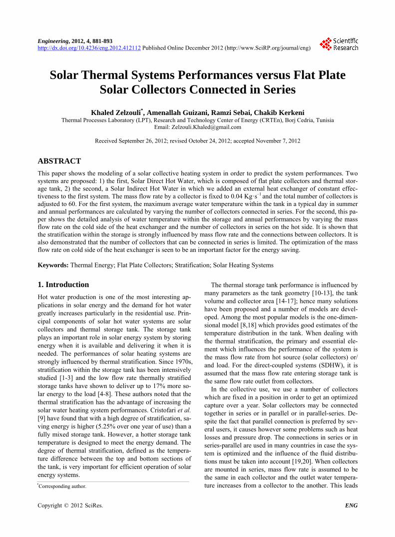
The two chosen system configurations, SDHW (Figure 1.1) and SIHW (Figure 1.2) are composed of: - An array of 60 identical flat plate collectors with total
area of 120 m2, and mass flow rate of 0.04 kg/s by collector according to the ASHRAE standard mass flow rate for testing conventional flat plate solar wa- ter collectors (0.02Ac kg/s, [31]). Tunisia is charac- terized by a temperate and an abundant sunshine for the most periods of the year [32,33], and the optimum
C1
1
2
R
Mains water
collectors
Storage
tank
To user
Figure 1.1. Direct Coupled System (SDHW). 1: Mixing de- vice; 2: Auxiliary heater.
Copyright © 2012 SciRes. ENG
K. ZELZOULI ET AL. 883
HXC1 C2
R
1
2
To user
Mains water
Collectors
Storage tank
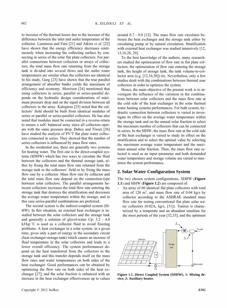
Figure 1.2. Indirect Coupled System (SIHW). 1: Mixing device; 2: Auxiliary heater.
slope angle of flat plate collectors is equal to the lati- tude [30]. The latitude, longitude, elevation above sea level and the annual average clearness index of Tunis City are respectively 36˚50'N, 10˚11'E, 0 m, and 0.53 [34].
- A 8 m3 vertical cylindrical storage tank having a ratio of height on diameter equal to 3, with an insulation made of polyurethane and a thickness equal to 50 mm.
- An auxiliary heater used for heating when the tem- perature of the water outgoing from the storage to the user is lower than the demand temperature required.
- A water-mixing device used to balance the tempera- ture by adding the mains water temperature before consuming it directly by the user.
- For the indirect-system, a constant effectiveness coun- ter current flow heat exchanger is installed between the collectors and the storage tank to transfer the heat from the hot source to the storage; Two pumps insure the fluid circulation between the heat exchanger and the collectors, and between the heat exchanger and the storage tank.
- For the direct-system, a circulator pump is installed between the collectors and the storage tank.
- An ON/OFF differential controller generates the ON/ OFF signals for the pumps operation.
The pumps are controlled by a differential thermostat that turns when the water temperature at the top collec- tors is higher than the water temperature at the bottom tank. A sufficient margin is then ensured to control the stability. The flow is ON if collectors outlet temperature exceeds the tank bottom temperature and OFF otherwise.
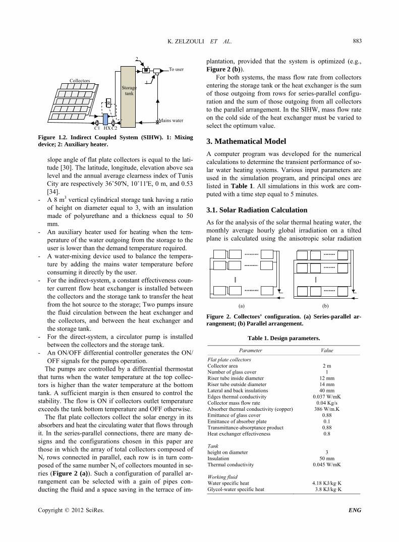
The flat plate collectors collect the solar energy in its absorbers and heat the circulating water that flows through it. In the series-parallel connections, there are many de- signs and the configurations chosen in this paper are those in which the array of total collectors composed of Nr rows connected in parallel, each row is in turn com- posed of the same number Nc of collectors mounted in se- ries (Figure 2 (a)). Such a configuration of parallel ar- rangement can be selected with a gain of pipes con- ducting the fluid and a space saving in the terrace of im-
plantation, provided that the system is optimized (e.g., Figure 2 (b)).
For both systems, the mass flow rate from collectors entering the storage tank or the heat exchanger is the sum of those outgoing from rows for series-parallel configu- ration and the sum of those outgoing from all collectors to the parallel arrangement. In the SIHW, mass flow rate on the cold side of the heat exchanger must be varied to select the optimum value.
3. Mathematical Model
A computer program was developed for the numerical calculations to determine the transient performance of so- lar water heating systems. Various input parameters are used in the simulation program, and principal ones are listed in Table 1. All simulations in this work are com- puted with a time step equal to 5 minutes.
3.1. Solar Radiation Calculation
As for the analysis of the solar thermal heating water, the monthly average hourly global irradiation on a tilted plane is calculated using the anisotropic solar radiation
(a) (b)
Figure 2. Collectors’ configuration. (a) Series-parallel ar- rangement; (b) Parallel arrangement.
Table 1. Design parameters.
Parameter Value
Flat plate collectors Collector area Number of glass cover Riser tube inside diameter Riser tube outside diameter Lateral and back insulations Edges thermal conductivity Collector mass flow rate Absorber thermal conductivity (copper) Emittance of glass cover Emittance of absorber plate
Transmittance-absorptance product Heat exchanger effectiveness Tank height on diameter Insulation Thermal conductivity Working fluid Water specific heat Glycol-water specific heat
2 m
1
12 mm 14 mm 40 mm
0.037 W/mK 0.04 Kg/s
386 W/m.K 0.88 0.1 0.88 0.8
3 50 mm
0.045 W/mK
4.18 KJ/kg·K 3.8 KJ/kg·K
Copyright © 2012 SciRes. ENG
K. ZELZOULI ET AL. 884
diffuse model based on the Hay-Davies-Klucher-Reindl (HDKR) model [35]. It refers to the integration of Klu- cher, 1979; Hay and Davis, 1980; Reindl et al. [36-38] model. The model considers the beam radiation, all com- ponents of diffuse radiation and the ground reflection to find the total radiation on the tilted surface. Comparatively with other models, HDKR is one of the most popular and provide significantly more accurate prediction [39-42].
According to the HDKR model the total solar radiance G on a tilted surface, whose tilt angle is β degrees from the horizontal, can be evaluated from the following equa- tion [35]:
3
1 cos1
21 cos
1 sin 22
b d i b d i
m b d g
G G G A R G A
f G G
(1)
where: b is the monthly average hourly beam irradia-tion on a horizontal plane; d is the monthly average hourly diffuse irradiation on a horizontal plane.
GG
The modulating factor is
m b b df G G G (2)
g is the surrounding diffuse reflectance (0.2 for non-snow surfaces). The geometric factor Rb is the ratio of beam radiation on tilted surface to that on a horizontal surface at any time. It is defined as:
cos cosbR z (3)
The incidence angle (θ) of beam radiation on a surface is defined as the angle between the beam radiation and the normal to a surface with any orientation. For the hori- zontal surface, the incidence angle is the zenith angle θZ of the sun and is defined as the angle between the ver- tical and the line to the sun. The value of the zenith angle must be between 0˚ and 90˚ when the sun is above the horizon, for this situation 0 . The optimum azimuth angle for flat-plate-collectors is usually 0˚ in the northern hemisphere. The geometric factor obtained as [30]:
cos cos cos sin sin
cos cos cos sin sinbR
(4)
where is the declination of the sun, is the lati- tude, is the tilt angle and is the hour angle.
23.45sin 360 284 365nd (5)
15 12 t (6)
t is the time expressed in true solar time. In the Equation (1), Ai is defined as:
3601 0.033cos
365
cos cos cos sin sin
ni b sc
dA G G
where the solar constant sc is equal to G 21367 W m according to the World Meteorological Organization, dn is the dn
th day of the year.
3.2. Flat Plate Collectors
Solar collectors receive solar radiant energy and transfer it to the flowing fluid. The useful energy gain of the col- lector determines the temperature rise of the flowing fluid in terms of design and operational variables. Equa- tion (8) expresses the useful energy gain of a solar col- lector [31].
u c R L in aQ A F G U T T (8)
where FR is the collector heat removal factor, is the transmittance-absorbance product, UL is the overall loss coefficient, Ac is the collector area, G is the incident radiation. KinT and KaT are the fluid inlet and ambient temperatures respectively. According to the the- oretical flat plate collector model type 73, solar energy gain of a row of Nc identical collectors connected in se- ries is defined as [43]:
, , ,1
cN
u c R j L j in j aj
Q A F G U T T
(9)
The overall loss coefficient UL,j can be obtained by an empirical equation following the basic procedure of Hot- tel and Woertz [44], and Klein [45], based on more measurements. UL,j defined as:
,
,
,
2 2, ,
1
1
2 1 0.1331
0.005591
L j
g
ev
p j a
p j g
p j a p j a
g pg
p g v g
be
U
N
hT TC
T N f
T T T T
N fN
N h
U
(10)
where:
0.43 1 100 pe T
V
(11)
wind5.7 3.8vh (12)
wind convective heat transfer coefficient 2W m K .
1 0.089 0.1166 1 0.078v v p gf h h N (13) (7) 2 0 70
520 1 0.000051 ,70 if 70
C
(14)
Copyright © 2012 SciRes. ENG
K. ZELZOULI ET AL. 885
An iterative method is used to calculate the first value of UL by assuming the initial mean plate temperature by 10˚C. Then, the efficiency factor F can be calculated as follows:
,
,
1
1 1
π
L j
b i f iL j
UF
WC D hU D W D F
1
(15)
The fin efficiency factor is:
,
2
2
L j
ab
th m W DF
m W D
Um
k e
(16)
Knowing collector efficiency factor; heat removal fac- tor FR is then calculated as follows:
,,
,
1 expc p L j cR j
c L j c p
m C F U AF
A U m C
(17)
Mean plate temperature is calculated as:
,, , ,
, ,
1u j c p j in j R jL j R j
Q AT T F
U F
(18)
The outlet fluid temperature from a collector is used as the inlet to the next and is given as:
, , ,
0, ,
c R j L j in j a
j in jc p
A F G U T TT
m C
T (19)
If an external heat exchanger is used, a modified heat removal factor RF can be used to determine the useful energy : uQ
u c R L in aQ A F G t U T T (20)
with
collector
collector min
1 1pC R LR
R p p
mCA F UF
F mC mC
c
h
(21)
3.3. Heat Exchanger
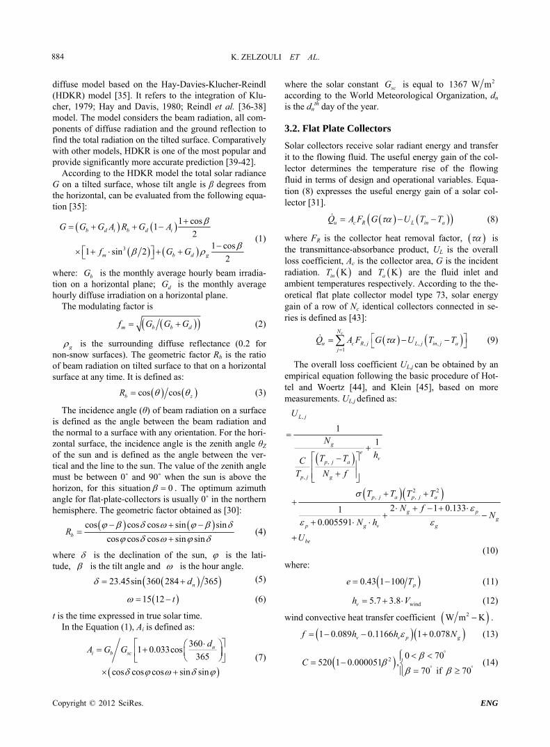
The following expressions are used to determine, for the constant heat exchanger effectiveness (Figure 3), the maximum possible amount of heat transfer rate based on the minimum capacity rate fluid and the cold side and hot side fluid inlet temperatures at a given time step [46].
In this mode the effectiveness is inputted as a parame-ter. The capacity rate of fluid on cold side is:
c cs pC m C (22)
The capacity rate of fluid on hot side is described by:
h hs pC m C (23)
The maximum capacity rate is:
max max ,c hC C C (24)
The minimum capacity rate is:
min min ,c hC C C
(25)
The maximum heat transfer rate across exchanger is:
max min hi ciQ C T T (26)
The actual heat transfer then depends upon the user specified effectiveness is:
maxTQ Q (27)
Lastly, the heat exchanger outlet conditions are calcu-lated for the two streams:
The hot side outlet temperature is:
Tho hi
h
QT T
C
(28)
The cold side outlet temperature is:
Tco ci
h
QT T
C
(29)
3.4. Thermal Stratified Storage Tank
When water bodies with rather different temperatures are put together in a quiet container (in a lake, a tank, etc.), water masses of different temperatures mix and exhibit a little relation to each other according to their density: the coldest down and the hottest up. Thus water bodies forms water layers of different temperatures at different heights, and so the name of stratification. This phenomenon is used in hot water tanks to separate hot and cold water and to avoid mixtures that produce only lukewarm water.
Thermal stratification in storage tanks has a significant positive effect on the system efficiency. Storage tanks are
hsm , hoT
hsm , hiT csm ,
coT
csm , ciT
TQ Cold side Hot side
Figure 3. Heat exchanger schematic.
Copyright © 2012 SciRes. ENG
K. ZELZOULI ET AL. 886
designed to avoid mixing of water of different tempera- tures in order to maintain good thermal stratification. In literature, numerous models have been developed to de- scribe these phenomena and among the most popular models, the one-dimensional model. Kleinbach et al. [8] studied three different 1-D models and concluded that the use of the multinode model is recommended. Papanico- laou and Belessiotis [18] found in their study that the mul- tinode model provides good estimates of the temperature distribution in the tank, in the case when there is at least a moderate amount of mixing.
Pumping cold fluid from the bottom to the solar col- lectors decreases its heat losses, and pumping hot water from the top to the load means that the less auxiliary hea- ting will be required. A hot storage tank temperature is desired in order to meet the energy demand with accept- able delivery temperature.
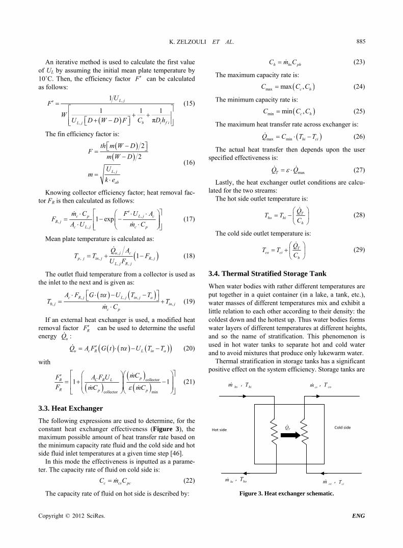
The storage tank considered in the aim of this work is a vertical cylinder of diameter Dt and height Ht as shown in Figure 4. The water tank is divided into N fully mixed equal volume segments. V is the total tank volume, V N is the volume of each segment and each segment has a uniform temperature Ti where The top segment
1, , .i N 1i has the highest temperature (lowest
density) and the bottom segment has the lowest temperature (highest density). The degree of stratification is determined by the choice of N. Higher values of N can be used to simulate a higher degree of stratification. The model assumes that the inlet hot water will flow to a sec-tion at the same temperature.
i N
An energy balance equation for the ith segment of wa- ter, taking into account of the axial heat conduction
between nodes, can be expressed as [8,30]: load,iq
heat, load, flow, cond, loss,
d
di
i p i i i i i
TM C q q q q q
t (30)
The left hand side of Equation (30) describes the change of internal energy in a node with the time.
heat,C
i h p i h iq m C F T T (31)
Figure 4. Stratified storage tank schematic.
heat,i represents the inflow of water returning from collectors into the segment of best matching temperature.
q
Collectors control function ciF is used to determine
which node receives collectors return water:
11 if
0 otherwisei h ic
i
T T TF
(32)
The inflow of cold water from the main is given by:
load, mains Li L p iq m C F T iT (33)
The liquid returning from the load controlled in a si- milar manner with control function L
iF such as:
11 if
0 otherwisei LL
i
T T TF
i (34)
1 if draw off is used
0 otherwise
(35)
The resultant intermodal flow, flow,i , into segment i is coming from the higher segment i − 1 and the lower segment i + 1.
q
The net flow between nodes can be either up or down depending on the magnitudes of the collectors and the load flow rates and the values of the two control func- tions c
iF and LiF at any particular instant. It is conven-
ient to define a mixed flow rate that represents the net flow into node i from node, I − 1 excluding the effects of flow directly into the node from load.
flow, 1 11i i T p i i i T p i iq m C T T m C T T (36)
1
1 1
i Nc
T h i L ij j i
m m F m F
L (37)
1 if 0
0 otherwiseT
i
m
(38)
The heat transfer due to conduction between the node above and below is described by:
cond, 1 1i
i i i it
N Sq T T T
H
iT (39)
The term of heat losses to the surroundings is:
loss,i s i iq U S T T a (40)
Th is the outlet water temperature from heat exchanger in the SIHW or outlet water temperature from collectors in the SDHW, that lowers the heat losses along the ducts.
4. Results and Discussions
4.1. Influence of Collectors Configuration on Temperature within Storage Tank: Direct-System
The water average temperature variation within the stor-
Copyright © 2012 SciRes. ENG
K. ZELZOULI ET AL. 887
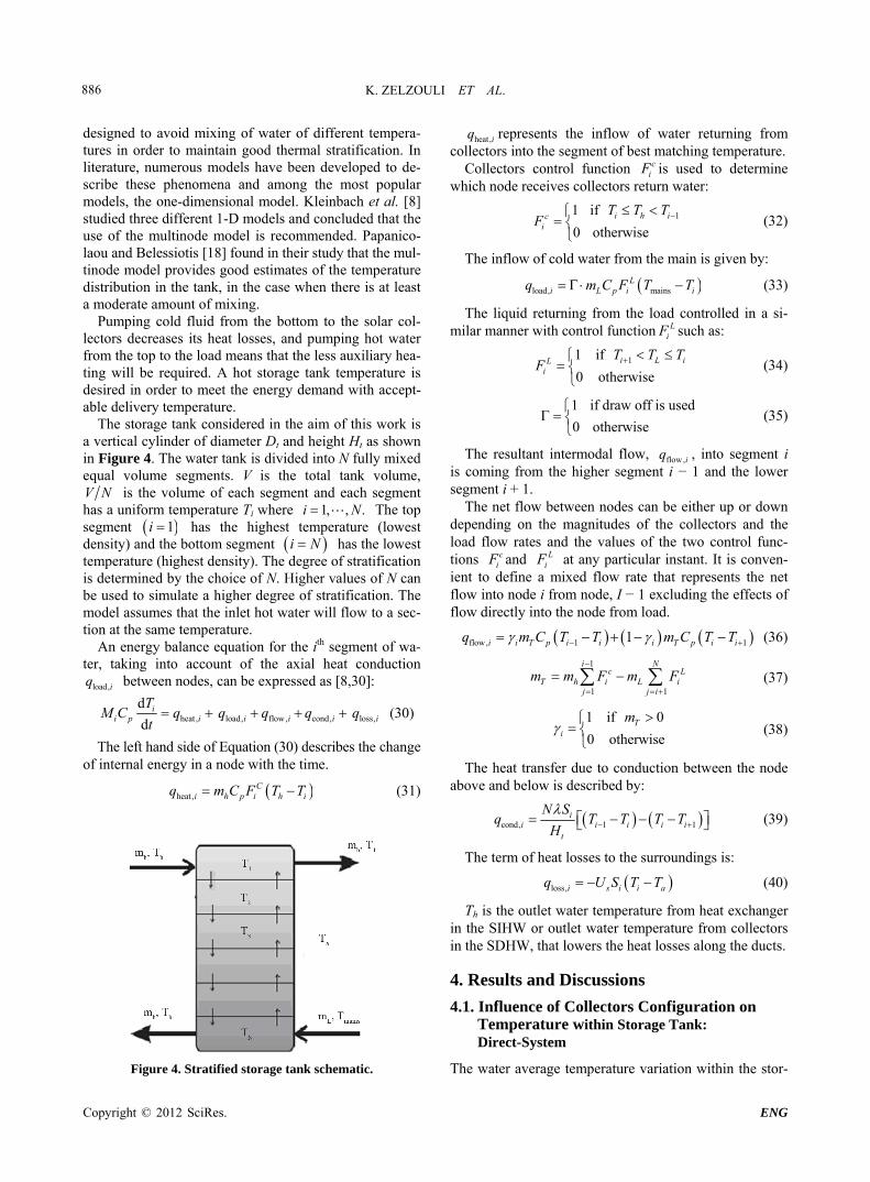
age tank depends on the outlet water temperature and mass flow rates from collectors. Series-parallel arrange- ments are designed with the objective of obtaining higher temperatures than only parallel arrangements. The field described in Figure 2 is composed of Nr parallel rows; each row is in turn composed of the same number Nc of collectors mounted in series. The temperature profile in the storage tank is observed by varying the number cN of collectors by a row. The number of parallel rows is calculated as 60 NcrN , e.g. a field is com- bined of 60, 30, 20, 15, 12 or 10 parallel rows composed of 1, 2, 3, 4, 5 or 6 collectors in series by row, respect- tively. Mass flow rate entering within the storage tank is the sum of those outgoing from the rows. In the follow- ing paragraph, the maximum water temperature in the storage, of 8 m3 initially at 23˚C, is calculated during the charging for different number Nc of series collectors at fixed mass flow rate 0.04kg scm by collector.
Numerical results are given in Figure 5 showing the water average temperature within the storage in a typical day in July characterized by an ambient temperature (Ta) of 34˚C at 2 pm and maximum irradiance (G) of 900 W/m2 at 12 am. For all collectors connected in parallel 1cN , the total mass flow rate entering within the storage is the sum of those outgoing from collectors
60
2cN
1h c and the maximum temperature is 57˚C at 5 pm. For a row of 2 collectors in series
, the number of parallel rows
2.4 kg sm m
rN is 30 and the mass flow rate entering within the storage is
301h c . The curve shows that the aver- age temperature increases from 57˚C to 64˚C
1.2 kg s m m = 7 CT
as the mass flow rate decreases from 2.4 to 1.2 kg s ..
For the case of 3 collectors by row , the num- ber of parallel rows is 20 and the total mass flow rate en- tering the storage is
3c N
20m m
1h c . The aver- age water temperature is increased from 64˚C to 67˚C as the mass flow rate decreased from 1.2 to 0.8
0.8 kg s
kg s . When using 4 collectors by row (15 parallel rows), the total
Figure 5. Hourly variation in average water temperature within storage tank by varying the number of collectors connected in series.
mass flow rate entering the storage is 15
1h c and the storage average water temperature increased to 69˚C. The curves have shown that the temperature difference ΔT decreases if a collec- tor in series is added and that from the 5th collector the average water temperature in the storage is the same, which explains that no output produced from the 6th. In this case, 5 is the maximum number put in series.
0.6 kg sm m
4.2. Influence of Mass Flow Rate on Stratification: Indirect-System
High flow rate has an advantage on the system perform- ance; it is recommended to maintain low collector tem- peratures and to maximize the internal heat transfer coef- ficient in the collector. However, the disadvantage of high flow rates is that the thermal stratification within the storage is disturbed even if a heat exchanger is used. Cir- culation pump mixes the water layers and a lower flow rate is needed if the stratification characteristics are to be preserved. Kim et al. [17] found in their study that the high flow rates cause greater mixing due to stronger con- vection resulting in a nearly uniform temperature in the storage tank. Moreover, they found that the uniform tem- perature is maintained throughout the day with a large temperature drop due to the high recirculation flow rate. Baek et al. [47] found in their study that the temperatures difference between top and bottom in the storage tank decreases if the mass flow rate increases and showed that higher thermal stratification in the storage tank can be achieved by using a smaller flow rate. Cristofari et al. [9] studied the influence of the flow rate and the tank strati- fication degree on the performances of a solar flat-plate collector; they found that the mixing is caused by enhan- cing the flow rate. In other hand, a previous study [9, 48] showed that 10 layers are sufficient to model accurately the stratification of a seasonal storage tank.
We consider a constant heat exchanger effectiveness 0.8 with vertical cylindrical storage tank compo- sed of 10 layers of equal volume. Charging storage tank (without draw off), by assuming that the water within the storage is initially held at a uniform temperature of 23˚C. The flow rate of fluid in loop collectors- heat exchanger is fixed to 0.04 kg/s by collector and the flow rate in loop heat exchanger-storage tank was varied to observe its ef- fect on stratification and on the average water tempera- ture. Numerical results, Figures 6.1-6.3, showed that mini- mizing the flow rate has an effect to observe stratification.
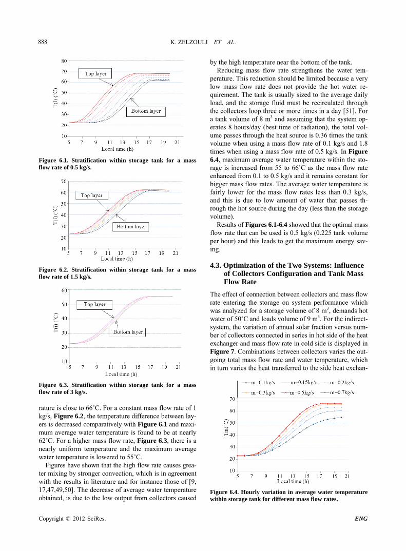
In Figure 6.1, the mass flow rate used is 0.5 kg/s, stra- tification is observed and the temperature difference be- tween layers exists. At 6 am, when solar radiation starts to increase, top layer of water temperature starts to inc- rease and reach maximum at 14 h while the bottom layer temperature begins to increase from 10 am and reach the maximum at 5 pm. The maximum average water tempe-
Copyright © 2012 SciRes. ENG
K. ZELZOULI ET AL. 888
Figure 6.1. Stratification within storage tank for a mass flow rate of 0.5 kg/s.
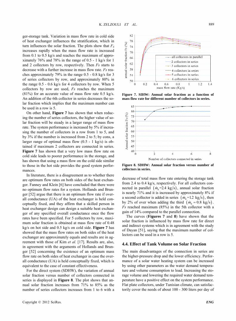
Figure 6.2. Stratification within storage tank for a mass flow rate of 1.5 kg/s.
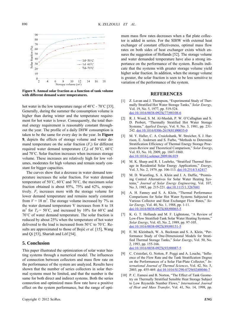
Figure 6.3. Stratification within storage tank for a mass flow rate of 3 kg/s. rature is close to 66˚C. For a constant mass flow rate of 1 kg/s, Figure 6.2, the temperature difference between lay- ers is decreased comparatively with Figure 6.1 and maxi- mum average water temperature is found to be at nearly 62˚C. For a higher mass flow rate, Figure 6.3, there is a nearly uniform temperature and the maximum average water temperature is lowered to 55˚C.
Figures have shown that the high flow rate causes grea- ter mixing by stronger convection, which is in agreement with the results in literature and for instance those of [9, 17,47,49,50]. The decrease of average water temperature obtained, is due to the low output from collectors caused
by the high temperature near the bottom of the tank. Reducing mass flow rate strengthens the water tem-
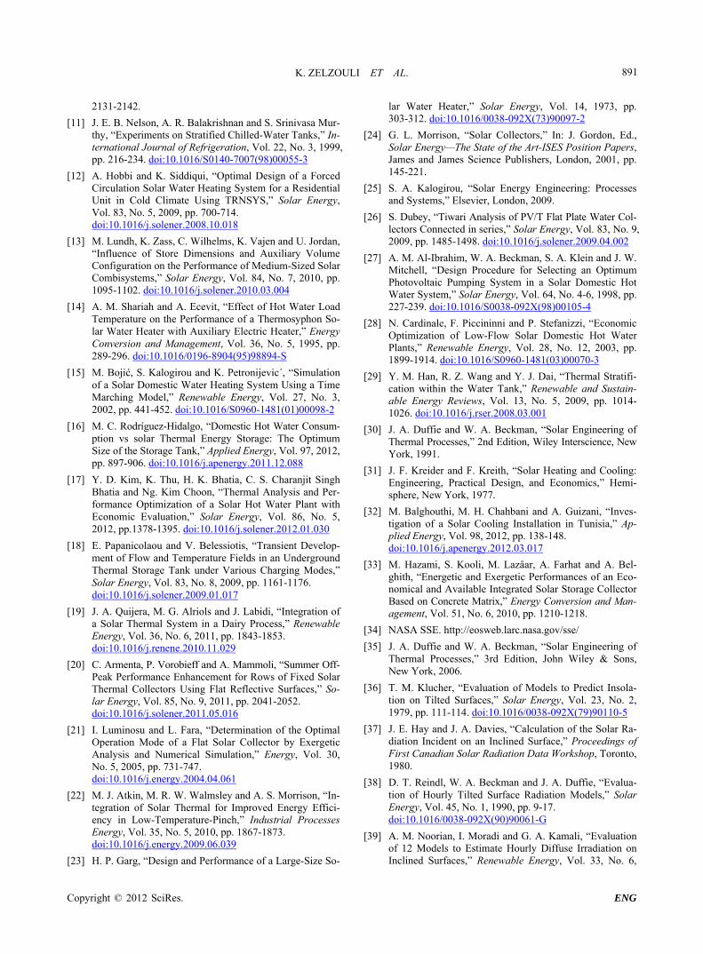
perature. This reduction should be limited because a very low mass flow rate does not provide the hot water re- quirement. The tank is usually sized to the average daily load, and the storage fluid must be recirculated through the collectors loop three or more times in a day [51]. For a tank volume of 8 m3 and assuming that the system op- erates 8 hours/day (best time of radiation), the total vol- ume passes through the heat source is 0.36 times the tank volume when using a mass flow rate of 0.1 kg/s and 1.8 times when using a mass flow rate of 0.5 kg/s. In Figure 6.4, maximum average water temperature within the sto- rage is increased from 55 to 66˚C as the mass flow rate enhanced from 0.1 to 0.5 kg/s and it remains constant for bigger mass flow rates. The average water temperature is fairly lower for the mass flow rates less than 0.3 kg/s, and this is due to low amount of water that passes th- rough the hot source during the day (less than the storage volume).
Results of Figures 6.1-6.4 showed that the optimal mass flow rate that can be used is 0.5 kg/s (0.225 tank volume per hour) and this leads to get the maximum energy sav- ing.
4.3. Optimization of the Two Systems: Influence of Collectors Configuration and Tank Mass Flow Rate
The effect of connection between collectors and mass flow rate entering the storage on system performance which was analyzed for a storage volume of 8 m3, demands hot water of 50˚C and loads volume of 9 m3. For the indirect- system, the variation of annual solar fraction versus num- ber of collectors connected in series in hot side of the heat exchanger and mass flow rate in cold side is displayed in Figure 7. Combinations between collectors varies the out- going total mass flow rate and water temperature, which in turn varies the heat transferred to the side heat exchan-
Figure 6.4. Hourly variation in average water temperature within storage tank for different mass flow rates.
Copyright © 2012 SciRes. ENG
K. ZELZOULI ET AL. 889
ger-storage tank. Variation in mass flow rate in cold side of heat exchanger influences the stratification, which in turn influences the solar fraction. The plots show that FS increases rapidly when the mass flow rate is increased from 0.1 to 0.5 kg/s and reaches the maximum of appro- ximately 76% and 78% in the range of 0.5 - 1 kg/s for 1 and 2 collectors by row, respectively. Then Fs starts to decrease with a further increase in mass flow rate. Fs rea- ches approximately 79% in the range 0.5 - 0.8 kg/s for 3 of series collectors by row, and approximately 80% in the range 0.5 - 0.6 kg/s for 4 collectors by row. When 5 collectors by row are used, Fs reaches the maximum (81%) for an accurate value of mass flow rate 0.5 kg/s. An addition of the 6th collector in series decreases the so- lar fraction which implies that the maximum number can be used in a row is 5.
On other hand, Figure 7 has shown that when reduc- ing the number of series collectors, the higher value of so- lar fraction will be steady in a larger range of mass flow rate. The system performance is increased by 5% if increa- sing the number of collectors in a row from 1 to 5, and by 3% if the number is increased from 2 to 5; by cons, a larger range of optimal mass flow (0.5 - 1 kg/s) is ob- tained if maximum 2 collectors are connected in series. Figure 7 has shown that a very low mass flow rate on cold side leads to poorer performance in the storage, and has shown that using a mass flow on the cold side similar to those in the hot side provides the good system perfor- mances.
In literature, there is a disagreement as to whether there are optimum flow rates on both sides of the heat exchan- ger. Fanney and Klein [6] have concluded that there were no optimum flow rates for a system. Hollands and Brun- ger [52] argue that there is an optimum flow rate if over- all conductance (UA) of the heat exchanger is held con- ceptually fixed, and they affirm that a skilled person in heat exchanger design can design a suitable heat exchan- ger of any specified overall conductance once the flow rates have been specified. For 5 collectors by row, maxi- mum solar fraction is obtained at mass flow rate of 0.48 kg/s on hot side and 0.5 kg/s on cold side. Figure 7 has showed that the mass flow rates on both sides of the heat exchanger are approximately equals and results are in ag- reement with those of Kim et al. [17]. Results are, also, in agreement with the arguments of Hollands and Brun- ger [52] concerning the existence of an optimum mass flow rate on both sides of heat exchanger in case the over- all conductance (UA) is held conceptually fixed, which is equivalent to the case of constant effectiveness.
For the direct system (SDHW), the variation of annual solar fraction versus number of collectors connected in series is displayed in Figure 8. The plot shows that an- nual solar fraction increases from 71% to 85% as the number of series collectors increases from 1 to 6 with a
Figure 7. SIHW: Annual solar fraction as a function of mass flow rate for different number of collectors in series.
Figure 8. SDHW: Annual solar fraction versus number of collectors in series. decrease of total mass flow rate entering the storage tank from 2.4 to 0.4 kg/s, respectively. For all collectors con- nected in parallel =2.4 kg shm , annual solar fraction is nearly 71% and it is increased by approximately 8% if a second collector is added in series =1.2 kg shm , then by 2% of over when adding the third 0.8 kg shm . Fs reached maximum (85%) in the 5th collector with a gain of 14% compared to the parallel connection.
The curves (Figures 7 and 8) have shown that the solar fraction is influenced by mass flow rate for direct and indirect systems which is in agreement with the study of Dayan [51], saying that the maximum number of col- lectors can be used in a row is 5.
4.4. Effect of Tank Volume on Solar Fraction
The main disadvantages of the connection in series are the higher-pressure drop and the lower efficiency. Perfor- mance of a solar water heating system can be increased by using other parameters as the water demand tempera- ture and volume consumption to load. Increasing the sto- rage volume and lowering the required water demand tem- perature have a positive effect on the system performance. Flat plate collectors, under Tunisian climate, can satisfac- torily cover the needs of about 100 - 300 liters per day of
Copyright © 2012 SciRes. ENG
K. ZELZOULI ET AL. 890
Figure 9. Annual solar fraction as a function of tank volume with different demand water temperatures.
hot water in the low temperature range of 40˚C - 70˚C [33]. Generally, during the summer the consumption volume is higher than during winter and the temperature require- ment for hot water is lower. Consequently, the total ther- mal energy requirement is reasonably constant through- out the year. The profile of a daily DHW consumption is taken to be the same for every day in the year. In Figure 9, depicts the effects of storage volume and water de- mand temperature on the solar fraction (Fs) for different required water demand temperature (Td) of 50˚C, 60˚C and 70˚C. Solar fraction increases when increases storage volume. These increases are relatively high for low vol- umes, moderates for high volumes and remain nearly con- stant for bigger capacities.
The curves show that a decrease in water demand tem- perature increases the solar fraction. For water demand temperature of 50˚C, 60˚C and 70˚C, the maximum solar fraction obtained is about 85%, 75% and 62%, respec- tively. Fs increases more with the storage volume for lower demand temperature and remains nearly constant from V = 18 m3. The storage volume increased by 7% as the water demand temperature V increases from 8 to 18 m3 for Td = 50˚C, and increased by 10% for 60˚C and 70˚C of water demand temperature. The solar fraction is reduced by about 25% when the temperature of hot water delivered to the load is increased from 50˚C to 70˚C. Re- sults are approximated to those of Bojić et al. [15], Wang and Qi [53], Shariah and Löf [54].
5. Conclusion
This paper illustrated the optimization of solar water hea- ting systems through a numerical model. The influences of connection between collectors and mass flow rate on the performance of the system are analyzed. Results have shown that the number of series collectors in solar ther- mal systems must be limited, and that the number is the same for both direct and indirect systems. Both the series connection and optimized mass flow rate have a positive effect on the system performance, but the range of opti-
mum mass flow rates decreases when a flat plate collec- tor is added in series. For the SIHW with external heat exchanger of constant effectiveness, optimal mass flow rates on both sides of heat exchanger exists which en- sures the suggestion of Hollands [52]. The storage volume and water demanded temperature have also a strong im- portance on the performance of the system. Results indi- cate that the systems with greater storage volume yield higher solar fraction. In addition, when the storage volume is greater, the solar fraction is seen to be less sensitive to variation of the performance of the system.
REFERENCES [1] Z. Lavan and J. Thompson, “Experimental Study of Ther-
mally Stratified Hot Water Storage Tanks,” Solar Energy, Vol. 19, No. 5, 1977, pp. 519-524. doi:10.1016/0038-092X(77)90108-6
[2] R. J. Wood, S. M. Al-Muslah, P. W. O’Callaghan and S. D. Probert, “Thermally Stratified Hot Water Storage Systems,” Applied Energy, Vol. 9, No. 3, 1981, pp. 231- 242. doi:10.1016/0306-2619(81)90035-0
[3] M. Y. Haller, C. A. Cruickshank, W. Streicher, S. J. Har-rison, E. Andersen and S. Furbo, “Methods to Determine Stratification Efficiency of Thermal Energy Storage Proc- esses-Review and Theoretical Comparison,” Solar Energy, Vol. 83, No. 10, 2009, pp. 1847-1860. doi:10.1016/j.solener.2009.06.019
[4] M. K. Sharp and R. I. Loehrke, “Stratified Thermal Stor- age in Residential Solar Energy Applications,” Energy, Vol. 3, No. 2, 1979, pp. 106-113. doi:10.2514/3.62417
[5] M. D. Wuestling, S. A. Klein and J. A. Duffie, “Promis- ing Control Alternatives for Solar Water Heating Sys- tems,” Journal of Solar Energy Engineering, Vol. 107, No. 3, 1985, pp. 215-221. doi:10.1115/1.3267681
[6] A. H. Fanney and S. A. Klein, “Thermal Performance Comparisons for Solar Hot Water Systems Subjected to Various Collector and Heat Exchanger Flow Rates,” So- lar Energy, Vol. 40, No. 1, 1988, pp. 1-11. doi:10.1016/0038-092X(88)90065-5
[7] K. G. T. Hollands and M. F. Lightstone, “A Review of Low-Flow Stratified-Tank Solar Water Heating Systems,” Solar Energy, Vol. 43, No. 2, 1989, pp. 97-105. doi:10.1016/0038-092X(89)90151-5
[8] E. M. Kleinbach, W. A. Beckman and S. A. Klein, “Per- formance Study of One-Dimensional Models for Strati- fied Thermal Storage Tanks,” Solar Energy, Vol. 50, No. 2, 1993, pp. 155-166. doi:10.1016/0038-092X(93)90087-5
[9] C. Cristofari, G. Notton, P. Poggi and A. Louche, “Influ- ence of the Flow Rate and the Tank Stratification Degree on the Performances of a Solar Flat-Plate Collector,” In- ternational Journal of Thermal Sciences, Vol. 42, No. 5, 2003, pp. 455-469. doi:10.1016/S1290-0729(02)00046-7
[10] P. C. Eamesi and B. Norton, “The Effect of Tank Geome- try on Thermally Stratified Sensible Heat Storage Subject to Low Reynolds Number Flows,” International Journal of Heat and Mass Transfer, Vol. 41, No. 14, 1998, pp.
Copyright © 2012 SciRes. ENG
K. ZELZOULI ET AL. 891
2131-2142.
[11] J. E. B. Nelson, A. R. Balakrishnan and S. Srinivasa Mur- thy, “Experiments on Stratified Chilled-Water Tanks,” In- ternational Journal of Refrigeration, Vol. 22, No. 3, 1999, pp. 216-234. doi:10.1016/S0140-7007(98)00055-3
[12] A. Hobbi and K. Siddiqui, “Optimal Design of a Forced Circulation Solar Water Heating System for a Residential Unit in Cold Climate Using TRNSYS,” Solar Energy, Vol. 83, No. 5, 2009, pp. 700-714. doi:10.1016/j.solener.2008.10.018
[13] M. Lundh, K. Zass, C. Wilhelms, K. Vajen and U. Jordan, “Influence of Store Dimensions and Auxiliary Volume Configuration on the Performance of Medium-Sized Solar Combisystems,” Solar Energy, Vol. 84, No. 7, 2010, pp. 1095-1102. doi:10.1016/j.solener.2010.03.004
[14] A. M. Shariah and A. Ecevit, “Effect of Hot Water Load Temperature on the Performance of a Thermosyphon So- lar Water Heater with Auxiliary Electric Heater,” Energy Conversion and Management, Vol. 36, No. 5, 1995, pp. 289-296. doi:10.1016/0196-8904(95)98894-S
[15] M. Bojić, S. Kalogirou and K. Petronijevic´, “Simulation of a Solar Domestic Water Heating System Using a Time Marching Model,” Renewable Energy, Vol. 27, No. 3, 2002, pp. 441-452. doi:10.1016/S0960-1481(01)00098-2
[16] M. C. Rodríguez-Hidalgo, “Domestic Hot Water Consum- ption vs solar Thermal Energy Storage: The Optimum Size of the Storage Tank,” Applied Energy, Vol. 97, 2012, pp. 897-906. doi:10.1016/j.apenergy.2011.12.088
[17] Y. D. Kim, K. Thu, H. K. Bhatia, C. S. Charanjit Singh Bhatia and Ng. Kim Choon, “Thermal Analysis and Per- formance Optimization of a Solar Hot Water Plant with Economic Evaluation,” Solar Energy, Vol. 86, No. 5, 2012, pp.1378-1395. doi:10.1016/j.solener.2012.01.030
[18] E. Papanicolaou and V. Belessiotis, “Transient Develop- ment of Flow and Temperature Fields in an Underground Thermal Storage Tank under Various Charging Modes,” Solar Energy, Vol. 83, No. 8, 2009, pp. 1161-1176. doi:10.1016/j.solener.2009.01.017
[19] J. A. Quijera, M. G. Alriols and J. Labidi, “Integration of a Solar Thermal System in a Dairy Process,” Renewable Energy, Vol. 36, No. 6, 2011, pp. 1843-1853. doi:10.1016/j.renene.2010.11.029
[20] C. Armenta, P. Vorobieff and A. Mammoli, “Summer Off- Peak Performance Enhancement for Rows of Fixed Solar Thermal Collectors Using Flat Reflective Surfaces,” So-lar Energy, Vol. 85, No. 9, 2011, pp. 2041-2052. doi:10.1016/j.solener.2011.05.016
[21] I. Luminosu and L. Fara, “Determination of the Optimal Operation Mode of a Flat Solar Collector by Exergetic Analysis and Numerical Simulation,” Energy, Vol. 30, No. 5, 2005, pp. 731-747. doi:10.1016/j.energy.2004.04.061
[22] M. J. Atkin, M. R. W. Walmsley and A. S. Morrison, “In- tegration of Solar Thermal for Improved Energy Effici- ency in Low-Temperature-Pinch,” Industrial Processes Energy, Vol. 35, No. 5, 2010, pp. 1867-1873. doi:10.1016/j.energy.2009.06.039
[23] H. P. Garg, “Design and Performance of a Large-Size So-
lar Water Heater,” Solar Energy, Vol. 14, 1973, pp. 303-312. doi:10.1016/0038-092X(73)90097-2
[24] G. L. Morrison, “Solar Collectors,” In: J. Gordon, Ed., Solar Energy—The State of the Art-ISES Position Papers, James and James Science Publishers, London, 2001, pp. 145-221.
[25] S. A. Kalogirou, “Solar Energy Engineering: Processes and Systems,” Elsevier, London, 2009.
[26] S. Dubey, “Tiwari Analysis of PV/T Flat Plate Water Col- lectors Connected in series,” Solar Energy, Vol. 83, No. 9, 2009, pp. 1485-1498. doi:10.1016/j.solener.2009.04.002
[27] A. M. Al-Ibrahim, W. A. Beckman, S. A. Klein and J. W. Mitchell, “Design Procedure for Selecting an Optimum Photovoltaic Pumping System in a Solar Domestic Hot Water System,” Solar Energy, Vol. 64, No. 4-6, 1998, pp. 227-239. doi:10.1016/S0038-092X(98)00105-4
[28] N. Cardinale, F. Piccininni and P. Stefanizzi, “Economic Optimization of Low-Flow Solar Domestic Hot Water Plants,” Renewable Energy, Vol. 28, No. 12, 2003, pp. 1899-1914. doi:10.1016/S0960-1481(03)00070-3
[29] Y. M. Han, R. Z. Wang and Y. J. Dai, “Thermal Stratifi- cation within the Water Tank,” Renewable and Sustain- able Energy Reviews, Vol. 13, No. 5, 2009, pp. 1014- 1026. doi:10.1016/j.rser.2008.03.001
[30] J. A. Duffie and W. A. Beckman, “Solar Engineering of Thermal Processes,” 2nd Edition, Wiley Interscience, New York, 1991.
[31] J. F. Kreider and F. Kreith, “Solar Heating and Cooling: Engineering, Practical Design, and Economics,” Hemi- sphere, New York, 1977.
[32] M. Balghouthi, M. H. Chahbani and A. Guizani, “Inves- tigation of a Solar Cooling Installation in Tunisia,” Ap- plied Energy, Vol. 98, 2012, pp. 138-148. doi:10.1016/j.apenergy.2012.03.017
[33] M. Hazami, S. Kooli, M. Lazâar, A. Farhat and A. Bel- ghith, “Energetic and Exergetic Performances of an Eco- nomical and Available Integrated Solar Storage Collector Based on Concrete Matrix,” Energy Conversion and Man- agement, Vol. 51, No. 6, 2010, pp. 1210-1218.
[34] NASA SSE. http://eosweb.larc.nasa.gov/sse/
[35] J. A. Duffie and W. A. Beckman, “Solar Engineering of Thermal Processes,” 3rd Edition, John Wiley & Sons, New York, 2006.
[36] T. M. Klucher, “Evaluation of Models to Predict Insola- tion on Tilted Surfaces,” Solar Energy, Vol. 23, No. 2, 1979, pp. 111-114. doi:10.1016/0038-092X(79)90110-5
[37] J. E. Hay and J. A. Davies, “Calculation of the Solar Ra- diation Incident on an Inclined Surface,” Proceedings of First Canadian Solar Radiation Data Workshop, Toronto, 1980.
[38] D. T. Reindl, W. A. Beckman and J. A. Duffie, “Evalua- tion of Hourly Tilted Surface Radiation Models,” Solar Energy, Vol. 45, No. 1, 1990, pp. 9-17. doi:10.1016/0038-092X(90)90061-G
[39] A. M. Noorian, I. Moradi and G. A. Kamali, “Evaluation of 12 Models to Estimate Hourly Diffuse Irradiation on Inclined Surfaces,” Renewable Energy, Vol. 33, No. 6,
Copyright © 2012 SciRes. ENG
K. ZELZOULI ET AL.
Copyright © 2012 SciRes. ENG
892
2008, pp. 1406-1412. doi:10.1016/j.renene.2007.06.027
[40] E. G. Evseev and A. I. Kudish, “The Assessment of Dif- ferent Models to Predict the Global Solar Radiation on a Surface Tilted to the South,” Solar Energy, Vol. 83, No. 3, 2009, pp. 377-388. doi:10.1016/j.solener.2008.08.010
[41] D. A. Chwieduk, “Recommendation on Modelling of So- lar Energy Incident on a Building Envelope,” Renewable Energy, Vol. 34, No. 3, 2009, pp. 736-741. doi:10.1016/j.renene.2008.04.005
[42] A. Padovan and D. Del Col, “Measurement and Modeling of Solar Irradiance Components on Horizontal and Tilted Planes,” Solar Energy, Vol. 84, No. 12, 2010, pp. 2068- 2084. doi:10.1016/j.solener.2010.09.009
[43] S. A. Klein, J. A. Duffie, J. C. Mitchell, J. P. Kummer, W. A. Beckmann, N. A. Duffie, et al., “TRNSYS16 a Tran- sient Simulation Program,” Solar Energy Laboratory, Uni- versity of Wisconsin-Madison, Madison, 2007, pp. 357- 359.
[44] H. C. Hottel and B. B. Woertz, “The Performance of Flat Plate Solar-Heat Collectors,” Transactions of the ASME, Vol. 64, 1942, pp. 64-91.
[45] S. A. Klein, “Calculation of Flat-Plate Collector Loss Co- efficients,” Solar Energy, Vol. 17, No. 1, 1975, pp. 79-80. doi:10.1016/0038-092X(75)90020-1
[46] S. A. Klein, J. A. Duffie, J. C. Mitchell, J. P. Kummer, W. A. Beckmann, N. A. Duffie, et al., “TRNSYS16 a Tran- sient Simulation Program,” Solar Energy Laboratory, Uni- versity of Wisconsin-Madison, Madison, 2007, pp. 117- 118.
[47] S. M. Baek, J. H. Namb, H. Hong and C. J. Kim, “Effect of Brine Flow Rate on the Performance of a Spiral-Jacke- ted Thermal Storage Tank Used for SDHW Systems: A Computational Fluid Dynamics Study,” Applied Thermal
Engineering, Vol. 31, No. 14-15, 2011, pp. 2716-2725. doi:10.1016/j.applthermaleng.2011.04.043
[48] J. E. Braun, S. A. Klein and J. W. Mitchell, “Seasonal Storage of Energy in Solar Heating,” Solar Energy, Vol. 26, No. 5, 1981, pp. 403-411. doi:10.1016/0038-092X(81)90219-X
[49] A. Mawire, M. McPherson and R. R. J. Van Den Heet- kamp, “Thermal Performance of a Small Oil-in-Glass Tube Thermal Energy Storage System during Charging,” En- ergy, Vol. 34, No. 7, 2009, pp. 838-849. doi:10.1016/j.energy.2009.02.016
[50] J. Ji, J. Han, T. T. Chow, H. Yi, J. Lu, W. He, et al., “Ef- fect of Fluid Flow and Packing Factor on Energy Perfor- mance of a Wall-Mounted Hybrid Photovoltaic/Water- Heating Collector System,” Energy and Buildings, Vol. 38, No. 12, 2006, pp. 1380-1387.
[51] M. Dayan, “High Performance in Low-Flow Domestic Hot Water Systems,” M.S. Thesis, University of Wiscon- sin-Madison, Madison, 1997.
[52] K. G. T. Hollands and A. P. Brunger, “Optimum Flow Rates in Solar Water Heating Systems with a Counter- flow Exchanger,” Solar Energy, Vol. 48, No. 1, 1992, pp. 15-19. doi:10.1016/0038-092X(92)90172-7
[53] H. Wang and C. Qi, “Performance Study of Underground Thermal Storage in a Solar-Ground Coupled Heat Pump System for Residential Buildings,” Energy and Buildings, Vol. 40, No. 7, 2008, pp. 1278-1286. doi:10.1016/j.enbuild.2007.11.009
[54] A. M. Shariah and G. O. G. Löf, “Effects of Auxiliary Heater on Annual Performance of Thermosyphon Solar Water Heater Simulated under Variable Operating Condi- tions,” Solar Energy, Vol. 60, No. 2, 1997, pp. 119-126. doi:10.1016/S0038-092X(96)00158-2
Nomenclature L Load
Mi Mass of layer, kg AC Collector area, m2
hm Mass flow rate entering/returning storage-hot source, kg/s Cp Specific heat of the working fluid, J/kg·K
D Riser tube outside diameter, m Lm Mass flow rate entering/returning storage-load,
kg/s Di Riser tube inside diameter, m Dt Tank diameter, m N Number of layers in storage eab Absorber plate thickness, m Nc Number of series collectors by row Fs Solar fraction, % Nr Number of parallel rows FR Heat removal factor Ng Number of glass covers F΄ Collector efficiency factor
uSi
Lateral area of layer in storage, m Q Useful energy gain of collector, W
F Fin efficiency G Solar radiation on titled collector, W/m2
Ta Air temperature, ˚C Ht Hight of storage tank, m Th Hot water inlet storage, ˚C hfi Convective heat transfer coefficient inside tube,
W/m2·K Ti Layer temperature, ˚C Tin Intel water temperature, ˚C
K Absorber thermal conductivity, W/m·K Tm Average water temperature, ˚C kb Bond thermal conductivity, W/m·K Tmains Cold water entering storage, ˚C
K. ZELZOULI ET AL. 893
T0 Outlet water temperature, ˚C Tp Mean temperature of absorber, ˚C
beU Bottom and edges loss coefficient, W/ m2·K UL Overall heat loss coefficient, W/m2·K Us Storage loss coefficient, W/m2·K V Volume of water in storage, m3 Vwind Wind speed, m/s W Distance between riser tubes, m Greek symbols λ Thermal conductivity, W/m·K β Collector tilt, deg (τα) Transmittance-absorptance product ε Heat exchanger effectiveness εg Emittance of glass cover εp Emittance of absorber plate
Copyright © 2012 SciRes. ENG