Embed Size (px)
Citation preview
8/7/2019 solar supercharge
http://slidepdf.com/reader/full/solar-supercharge 1/8
Energy Harvesting
July 1, 2010By: Pierre Mars, CAP-XX (Australia) Pty. Ltd.Sensors
Here's how supercapacitors—double-layered capacitors with the abilityto store far more energy that a traditional capacitor—can be used inconjunction with a small solar cell to power a wireless sensor node.
Wireless sensor networks (WSNs) are becoming more common. They solve problems in many
applications, some of which can harvest solar energy to use as a limitless, battery-free energy
source. In these applications a supercapacitor provides both temporary energy storage and power
delivery. Harvested solar energy can power motion sensors to turn off lights if nobody is detected in a
room, to dim lights depending on the light level in a room, to sense and report temperature for air
conditioning or heating, and to monitor the security of remote locations while avoiding the need to
replace and dispose of batteries.
However, small solar cells are very low power, delivering milliwatts of energy. So the problem
becomes how to power wireless transmission, which requires higher amounts of power, using a low-
power source.
What Are Supercapacitors? Supercapacitors are electrical double-layer capacitors. Their electrodes are made of porous carbon
and have surface areas >1000 m2/g, providing a huge charge storage area. The electrodes are keptapart by a porous separator that allows ions in solution in the electrolyte to pass through, providing
charge transport. The ions rest at the surface of the carbon electrode, so charge separation distance
is on the order of nanometers. The size of the charge storage area, coupled with the nanoscale
charge separation distance, provides the 'super' capacitance. Key parameters are capacitance (C ),
Equivalent Series Resistance (ESR), voltage, and volume or weight. Because supercapacitors
contain no dielectric, the maximum voltage is determined by the breakdown voltage of the electrolyte.
The highest maximum voltage available today is 2.7 V. Supercapacitors are connected in series to
achieve higher voltages and a voltage balancing circuit is required to ensure that no individual cell
goes overvoltage.
CAP-XX supercapacitors benefit from a nanotechnology construction that packs the highest energyand power densities into thin, prismatic packages that fit space-constrained devices. They store
charge on nanoporous carbon electrodes on aluminum foil, arranged in multiple layers, and
connected in parallel to minimize the resistance and maximize the capacitance of the device.
Supercapacitors as a Power Buffer
Before there were low-impedance supercapacitors, designers had to size the entire power supply
system for the load's peak power. For example, assume a sensor in a remote location is reporting its
status once an hour by sensing an SMS that takes 3 s to transmit over a GPRS cellular network. The
peak output power during transmission is ~7 W. The average power during the transmission = 7/8 W
for 3 s or ~2.6 J. If a capacitor is placed at the input of a buck-boost regulator to allow a wider voltage
window—with a maximum voltage of 5 V and minimum voltage of 2.5 V—then input peak power will
be ~7 W/85% efficiency or ~8.3 W, and the energy drawn will be ~3 J. To meet these requirements
you would require 0.4 F with ESR <50 m, or a supercapacitor. The alternative is to trickle-charge a
battery that can deliver this power, possibly with the support of a tantalum or electrolytic capacitor for
Using a Small Solar Cell and a Supercapacitor ina Wireless Sensor
Page 1 of 8Using a Small Solar Cell and a Supercapacitor in a Wireless Sensor | Sensors Magazine
7/16/2010http://www.sensorsmag.com/networking-communications/energy-harvesting/using-a-s...
8/7/2019 solar supercharge
http://slidepdf.com/reader/full/solar-supercharge 2/8
the 0.577 ms transmission peaks.
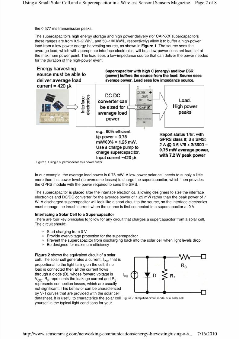
The supercapacitor's high energy storage and high power delivery (for CAP-XX supercapacitors
these ranges are from 0.5–2 Wh/L and 50–100 kW/L, respectively) allow it to buffer a high-power
load from a low-power energy-harvesting source, as shown in Figure 1. The source sees the
average load, which with appropriate interface electronics, will be a low-power constant load set at
the maximum power point. The load sees a low-impedance source that can deliver the power needed
for the duration of the high-power event.
In our example, the average load power is 0.75 mW. A low-power solar cell needs to supply a little
more than this power level (to overcome losses) to charge the supercapacitor, which then provides
the GPRS module with the power required to send the SMS.
The supercapacitor is placed after the interface electronics, allowing designers to size the interface
electronics and DC/DC converter for the average power of 1.25 mW rather than the peak power of 7
W. A discharged supercapacitor will look like a short circuit to the source, so the interface electronics
must manage the inrush current when the source is first connected to a supercapacitor at 0 V.
Interfacing a Solar Cell to a Supercapacitor
There are four key principles to follow for any circuit that charges a supercapacitor from a solar cell.
The circuit should:
Start charging from 0 V
Provide overvoltage protection for the supercapacitorPrevent the supercapacitor from discharging back into the solar cell when light levels dropBe designed for maximum efficiency
Figure 2 shows the equivalent circuit of a solarcell. The solar cell generates a current, IPH, that is
proportional to the light falling on the cell; if no
load is connected then all the current flows
through a diode (D), whose forward voltage isVOC. RP represents the leakage current and RS
represents connection losses, which are usually
not significant. This behavior can be characterized
by V- I curves that are provided with the solar cell
datasheet. It is useful to characterize the solar cellyourself in the typical light conditions for your
Figure 1. Using a supercapacitor as a power buffer
Figure 2. Simplified circuit model of a solar cell
Page 2 of 8Using a Small Solar Cell and a Supercapacitor in a Wireless Sensor | Sensors Magazine
7/16/2010http://www.sensorsmag.com/networking-communications/energy-harvesting/using-a-s...
8/7/2019 solar supercharge
http://slidepdf.com/reader/full/solar-supercharge 3/8
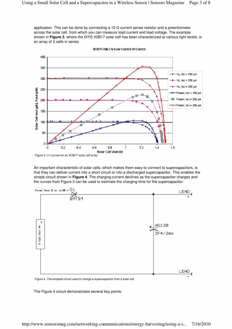
application. This can be done by connecting a 10 current sense resistor and a potentiometer
across the solar cell, from which you can measure load current and load voltage. The example
shown in Figure 3, where the IXYS X0B17 solar cell has been characterized at various light levels, is
an array of 3 cells in series.
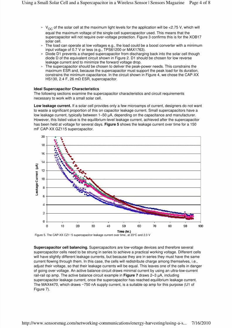
An important characteristic of solar cells, which makes them easy to connect to supercapacitors, is
that they can deliver current into a short circuit or into a discharged supercapacitor. This enables thesimple circuit shown in Figure 4. The charging current declines as the supercapacitor charges and
the curves from Figure 3 can be used to estimate the charging time for the supercapacitor.
The Figure 4 circuit demonstrates several key points:
Figure 3. V-I curves for an XOB17 solar cell array
Figure 4. The simplest circuit used to charge a supercapacitor from a solar cell
Page 3 of 8Using a Small Solar Cell and a Supercapacitor in a Wireless Sensor | Sensors Magazine
7/16/2010http://www.sensorsmag.com/networking-communications/energy-harvesting/using-a-s...
8/7/2019 solar supercharge
http://slidepdf.com/reader/full/solar-supercharge 4/8
VOC of the solar cell at the maximum light levels for the application will be <2.75 V, which will
equal the maximum voltage of the single-cell supercapacitor used. This means that thesupercapacitor will not require over-voltage protection. Figure 3 confirms this is for the XOB17solar cell.The load can operate at low voltages e.g., the load could be a boost converter with a minimuminput voltage of 0.7 V or less (e.g., TPS61200 or MAX1763).Diode D1 prevents a charged supercapacitor from discharging back into the solar cell though
diode D of the equivalent circuit shown in Figure 2. D1 should be chosen for low reverseleakage current and to minimize the forward voltage drop.The supercapacitor should be chosen to deliver the peak-power needs. This constrains themaximum ESR and, because the supercapacitor must support the peak load for its duration,constrains the minimum capacitance. In the circuit shown in Figure 4, we chose the CAP-XXHS130, 2.4 F, 26 m ESR, supercapacitor.
Ideal Supercapacitor Characteristics
The following sections examine the supercapacitor characteristics and circuit requirements
necessary to work with a small solar cell.
Low leakage current. If a solar cell provides only a few microamps of current, designers do not want
to waste a significant proportion of this on capacitor leakage current. Small supercapacitors have a
low leakage current, typically between 1–50 µA, depending on the capacitance and manufacturer.However, this listed value is the equilibrium-level leakage current, achieved after the supercapacitor
has been held at voltage for several days. Figure 5 shows the leakage current over time for a 150
mF CAP-XX GZ115 supercapacitor.
Supercapacitor cell balancing. Supercapacitors are low-voltage devices and therefore several
supercapacitor cells need to be strung in series to achieve a practical working voltage. Different cells
will have slightly different leakage currents, but because they are in series they must have the same
current flowing through them. In this case, the cells will redistribute charge among themselves, i.e.,
adjust their voltage, so that their leakage currents will be equal. This leaves one of the cells in danger
of going over voltage. An active balance circuit draws minimal current by using an ultra-low-current
rail-rail op amp. The active balance circuit example in Figure 7 draws 2–3 µA, including
supercapacitor leakage current, once the supercapacitor has reached equilibrium leakage current.
The MAX4470, which draws ~750 nA supply current, is a suitable op amp for this purpose (U1 of
Figure 7).
Figure 5. The CAP-XX CZ115 supercapacitor leakage current over time, at 23°C and 2.3 V
Page 4 of 8Using a Small Solar Cell and a Supercapacitor in a Wireless Sensor | Sensors Magazine
7/16/2010http://www.sensorsmag.com/networking-communications/energy-harvesting/using-a-s...
8/7/2019 solar supercharge
http://slidepdf.com/reader/full/solar-supercharge 5/8
Note that in CAP-XX dual-cell supercapacitors, the two cells are matched by capacitance. Because
their voltages are balanced when first charged, designers can use a very low-current balance circuit
to maintain this balance.
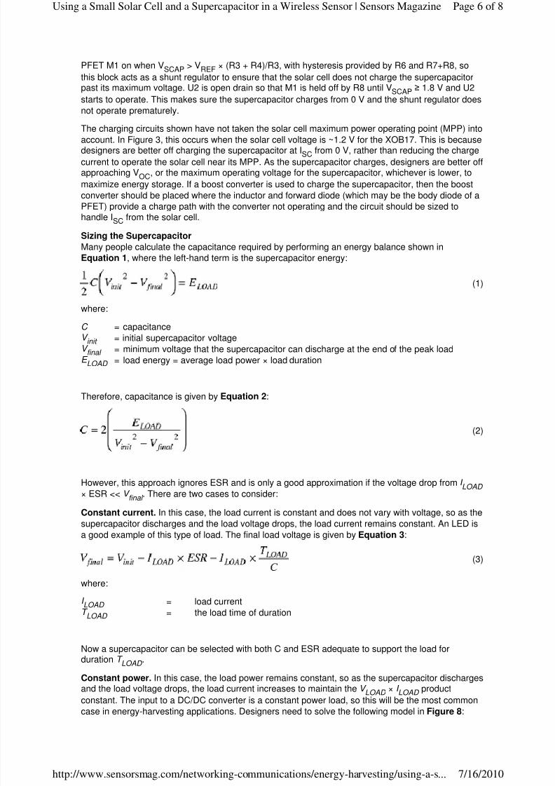
Aging. All supercapacitors age over time, i.e., their ESR slowly increases and their capacitance
slowly decreases. The rate of aging depends on the supercapacitor's operating voltage and
temperature; the higher the voltage and/or temperature, the faster it ages. Therefore, designers
should size the supercapacitor so that the C is large enough and ESR low enough for successful
operation at end of life, given the application's expected operating profile. Figure 6 shows
capacitance over time for 1 year for a CAP-XX GW214 supercapacitor at 3.6 V and room
temperature (23°C).
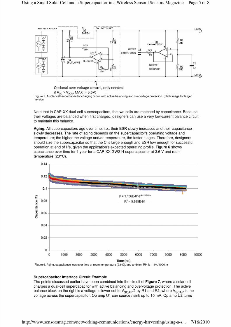
Supercapacitor Interface Circuit Example
The points discussed earlier have been combined into the circuit of Figure 7, where a solar cell
charges a dual-cell supercapacitor with active balancing and overvoltage protection. The activebalance block on the right is a voltage follower set to VSCAP/2 by R1 and R2, where VSCAP is the
voltage across the supercapacitor. Op amp U1 can source / sink up to 10 mA. Op amp U2 turns
Figure 7. A solar cell-supercapacitor charging circuit with active balancing and overvoltage protection (Click image for largerversion)
Figure 6. Aging, capacitance loss over time at room temperature (23°C), and ambient RH is 1.4%/1000 hr
Page 5 of 8Using a Small Solar Cell and a Supercapacitor in a Wireless Sensor | Sensors Magazine
7/16/2010http://www.sensorsmag.com/networking-communications/energy-harvesting/using-a-s...
8/7/2019 solar supercharge
http://slidepdf.com/reader/full/solar-supercharge 6/8
PFET M1 on when VSCAP > VREF × (R3 + R4)/R3, with hysteresis provided by R6 and R7+R8, so
this block acts as a shunt regulator to ensure that the solar cell does not charge the supercapacitorpast its maximum voltage. U2 is open drain so that M1 is held off by R8 until V SCAP ≥ 1.8 V and U2
starts to operate. This makes sure the supercapacitor charges from 0 V and the shunt regulator does
not operate prematurely.
The charging circuits shown have not taken the solar cell maximum power operating point (MPP) into
account. In Figure 3, this occurs when the solar cell voltage is ~1.2 V for the XOB17. This is becausedesigners are better off charging the supercapacitor at ISC from 0 V, rather than reducing the charge
current to operate the solar cell near its MPP. As the supercapacitor charges, designers are better offapproaching VOC, or the maximum operating voltage for the supercapacitor, whichever is lower, to
maximize energy storage. If a boost converter is used to charge the supercapacitor, then the boost
converter should be placed where the inductor and forward diode (which may be the body diode of a
PFET) provide a charge path with the converter not operating and the circuit should be sized tohandle ISC from the solar cell.
Sizing the Supercapacitor
Many people calculate the capacitance required by performing an energy balance shown in
Equation 1, where the left-hand term is the supercapacitor energy:
where:
Therefore, capacitance is given by Equation 2:
However, this approach ignores ESR and is only a good approximation if the voltage drop from I LOAD
× ESR << V final
. There are two cases to consider:
Constant current. In this case, the load current is constant and does not vary with voltage, so as the
supercapacitor discharges and the load voltage drops, the load current remains constant. An LED is
a good example of this type of load. The final load voltage is given by Equation 3:
where:
Now a supercapacitor can be selected with both C and ESR adequate to support the load forduration T
LOAD .
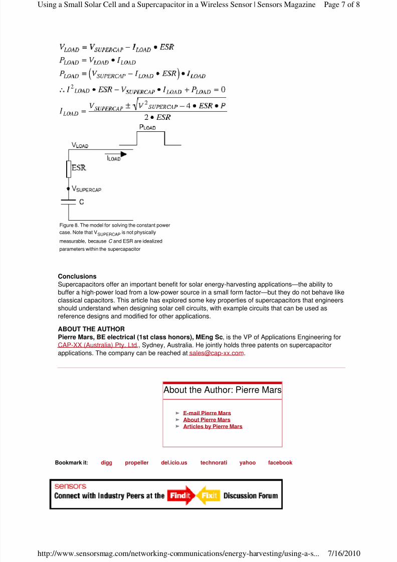
Constant power. In this case, the load power remains constant, so as the supercapacitor discharges
and the load voltage drops, the load current increases to maintain the V LOAD × I LOAD productconstant. The input to a DC/DC converter is a constant power load, so this will be the most common
case in energy-harvesting applications. Designers need to solve the following model in Figure 8:
(1)
C = capacitanceV init = initial supercapacitor voltage
V final = minimum voltage that the supercapacitor can discharge at the end of the peak load
E LOAD = load energy = average load power × load duration
(2)
(3)
I LOAD = load currentT LOAD = the load time of duration
Page 6 of 8Using a Small Solar Cell and a Supercapacitor in a Wireless Sensor | Sensors Magazine
7/16/2010http://www.sensorsmag.com/networking-communications/energy-harvesting/using-a-s...
8/7/2019 solar supercharge
http://slidepdf.com/reader/full/solar-supercharge 7/8
Bookmark it: digg propeller del.icio.us technorati yahoo facebook
Conclusions
Supercapacitors offer an important benefit for solar energy-harvesting applications—the ability to
buffer a high-power load from a low-power source in a small form factor—but they do not behave likeclassical capacitors. This article has explored some key properties of supercapacitors that engineers
should understand when designing solar cell circuits, with example circuits that can be used as
reference designs and modified for other applications.
ABOUT THE AUTHOR
Pierre Mars, BE electrical (1st class honors), MEng Sc, is the VP of Applications Engineering for
CAP-XX (Australia) Pty. Ltd., Sydney, Australia. He jointly holds three patents on supercapacitor
applications. The company can be reached at [email protected].
Figure 8. The model for solving the constant power
case. Note that VSUPERCAP is not physically
measurable, because C and ESR are idealized
parameters within the supercapacitor
E-mail Pierre Mars About Pierre Mars Articles by Pierre Mars
About the Author: Pierre Mars
Page 7 of 8Using a Small Solar Cell and a Supercapacitor in a Wireless Sensor | Sensors Magazine
7/16/2010http://www.sensorsmag.com/networking-communications/energy-harvesting/using-a-s...
8/7/2019 solar supercharge
http://slidepdf.com/reader/full/solar-supercharge 8/8
Page 8 of 8Using a Small Solar Cell and a Supercapacitor in a Wireless Sensor | Sensors Magazine