Embed Size (px)
Citation preview

TOOLKIT DOCUMENT #3
Solar PV Standard Plan — Simplified Central/String Inverter Systems for
One- and Two-Family Dwellings
Your Citylogo here
SCOPE: Use this plan ONLY for utility-interactive central/string inverter systems not exceeding a system AC inverter output rating of 10kW on the roof of a one- or two-family dwelling or accessory structure. The photovoltaic system must interconnect to the load side of a single-phase AC service panel of nominal 120/240Vac with a bus bar rating of 225A or less. This plan is not intended for bipolar systems, hybrid systems or systems that utilize storage batteries, charge controllers, trackers, more than two inverters or more than one DC combiner (noninverter-integrated) per inverter. Systems must be in compliance with current California Building Standards Codes and local amendments of the authority having jurisdiction (AHJ). Other Articles of the California Electrical Code (CEC) shall apply as specified in 690.3.
MANUFACTURER’S SPECIFICATION SHEETS MUST BE PROVIDED for proposed inverter, modules, combiner/junction boxes and racking systems. Installation instructions for bonding and grounding equipment shall be provided, and local AHJs may require additional details. Listed and labeled equipment shall be installed and used in accordance with any instructions included in the listing or labeling (CEC 110.3). Equipment intended for use with PV system shall be identified and listed for the application (CEC 690.4[D]).
Job Address: ______________________________________________ Permit #: ________________________
Contractor/ Engineer Name: ________________________________ License # and Class: _______________
Signature: _______________________________ Date: ___________ Phone Number: __________________
Total # of Inverters installed: __________ (If more than one inverter, complete and attach the “Supplemental Calculation Sheets” and the “Load Center Calculations” if a new load center is to be used.)
Inverter 1 AC Output Power Rating: _______________________ Watts
Inverter 2 AC Output Power Rating (if applicable): ____________ Watts
Combined Inverter Output Power Rating: ___________________ ≤ 10,000 Watts
Location Ambient Temperatures (Check box next to which lowest expected temperature is used):
1) Lowest expected ambient temperature for the location (TL) = Between -1 to -5 °C
Lowest expected ambient temperature for the location (TL) = Between -6 to -10 °C
Average ambient high temperature (TH) = 47 °C
Note: For a lower TL or a higher TH, use the Comprehensive Standard Plan
DC Information:
Module Manufacturer: __________________________ Model: ______________________________
2) Module Voc (from module nameplate): ______ Volts 3) Module Isc (from module nameplate): ______ Amps
4) Module DC output power under standard test conditions (STC) = ________ Watts (STC)
5) DC Module Layout
Identify each source circuit (string) for inverter 1 shown on the roof plan with a Tag
(e.g. A,B,C,…)Number of modules per
source circuit for inverter 1 Identify, by tag, which source circuits on the roof are to be
paralleled (if none, put N/A)
Combiner 1:
Combiner 2:
Total number of source circuits for inverter 1:
6) Are DC/DC Converters used? Yes No If No, skip to Step 7. If Yes enter info below.
DC/DC Converter Model #: __________________
Max DC Output Current: ____________________ Amps
Max # of DC/DC Converters in an Input Circuit: ___________
DC/DC Converter Max DC Input Voltage: ______ Volts
Max DC Output Current: ___________________ Volts
DC/DC Converter Max DC Input Power: _______ Watts
7) Maximum System DC Voltage — Use A1 or A2 for systems without DC/DC converters, and B1 or B2 with DC/DC Converters.
A1. Module VOC (STEP 2) = ____________ x # in series (STEP 5) ___________ x 1.12 (If -1 ≤ TL ≤ -5°C, STEP 1) = ____________ V
A2. Module VOC (STEP 2) = ____________ x # in series (STEP 5) ___________ x 1.14 (If -6 ≤ TL ≤ -10°C, STEP 1) = ___________ V
Table 1. Maximum Number of PV Modules in Series Based on Module Rated VOC for 600 Vdc Rated Equipment (CEC 690.7)
Max. Rated Module VOC (*1.12) (Volts) 29.76 31.51 33.48 35.71 38.27 41.21 44.64 48.70 53.57 59.52 66.96 76.53 89.29
Max. Rated Module VOC (*1.14) (Volts) 29.24 30.96 32.89 35.09 37.59 40.49 43.86 47.85 52.63 58.48 65.79 75.19 87.72
Max # of Modules for 600 Vdc 18 17 16 15 14 13 12 11 10 9 8 7 6
Use for DC/DC converters. The value calculated below must be less than DC/DC converter max DC input voltage (STEP 6).
B1. Module VOC (STEP 2) = ________ x # of modules per converter (STEP 6) ______ x 1.12 (If -1 ≤ TL ≤ -5°C, STEP 1) = _______ V
B2. Module VOC (STEP 2) = ________ x # of modules per converter (STEP 6) ______ x 1.14 (If -6 ≤ TL ≤ -10°C, STEP 1) = ______ V
Table 2. Largest Module VOC for Single-Module DC/DC Converter Configurations (with 80 V AFCI Cap) (CEC 690.7 and 690.11)
Max. Rated Module VOC (*1.12) (Volts) 30.4 33.0 35.7 38.4 41.1 43.8 46.4 49.1 51.8 54.5 57.1 59.8 62.5 65.2 67.9 70.5
Max. Rated Module VOC (*1.14) (Volts) 29.8 32.5 35.1 37.7 40.4 43.0 45.6 48.2 50.9 53.5 56.1 58.8 61.4 64.0 66.7 69.3
DC/DC Converter Max DC Input (Step #6) (Volts) 34 37 40 43 46 49 52 55 58 61 64 67 70 73 76 79
8) Maximum System DC Voltage from DC/DC Converters to Inverter — Only required if Yes in Step 6 Maximum System DC Voltage = _______________ Volts
9) Maximum Source Circuit Current Is Module ISC below 9.6 Amps (Step 3)? Yes No (If No, use Comprehensive Standard Plan)

10) Sizing Source Circuit Conductors Source Circuit Conductor Size = Min. #10 AWG copper conductor, 90°C wet (USE-2, PV Wire, XHHW-2, THWN-2, RHW-2) For up to 8 conductors in roof-mounted conduit exposed to sunlight at least ½” from the roof covering (CEC 310) Note: For over 8 conductors in the conduit or mounting height of lower than ½” from the roof, use Comprehensive Plan.
11) Are PV source circuits combined prior to the inverter? Yes No If No, use Single Line Diagram 1 and proceed to Step 13. If Yes, use Single Line Diagram 2 with Single Line Diagram 4 and proceed to Step 12. Is source circuit OCPD required? Yes No Source circuit OCPD size (if needed): 15 Amps
12) Sizing PV Output Circuit Conductors — If a combiner box will NOT be used (Step 11), Output Circuit Conductor Size = Min. #6 AWG copper conductor
13) Inverter DC Disconnect Does the inverter have an integrated DC disconnect? Yes No If Yes, proceed to step 14. If No, the external DC disconnect to be installed is rated for ______ Amps (DC) and ______ Volts (DC)
14) Inverter Information Manufacturer: ______________________________ Model: _______________________________Max. Continuous AC Output Current Rating: _______ Amps Integrated DC Arc-Fault Circuit Protection? Yes No (If No is selected, Comprehensive Standard Plan) Grounded or Ungrounded System? Grounded Ungrounded
AC Information:
15) Sizing Inverter Output Circuit Conductors and OCPD Inverter Output OCPD rating = ______ Amps (Table 3) Inverter Output Circuit Conductor Size = ______ AWG (Table 3)
Table 3. Minimum Inverter Output OCPD and Circuit Conductor Size
Inverter Continuous Output Current Rating (Amps) (Step 14) 12 16 20 24 28 32 36 40 48
Minimum OCPD Size (Amps) 15 20 25 30 35 40 45 50 60
Minimum Conductor Size (AWG, 75°C, Copper) 14 12 10 10 8 8 6 6 6
Integrated DC Arc-Fault Circuit Protection? Yes No (If No is selected, Comprehensive Standard Plan) Grounded or Ungrounded System? Grounded Ungrounded
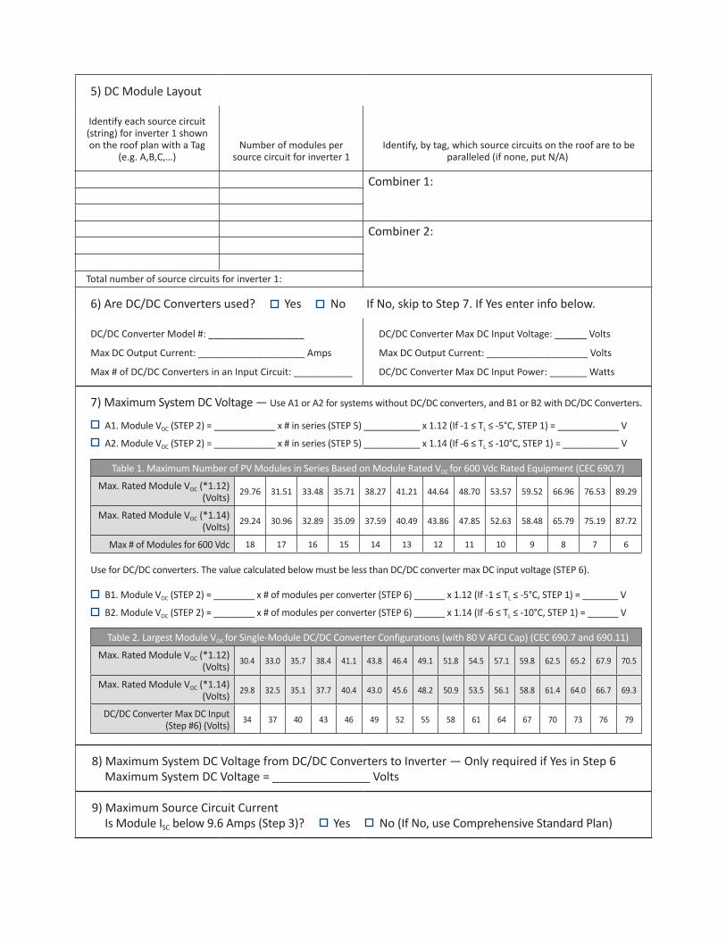
16) Point of Connection to Utility Only load side connections are permitted with this plan. Otherwise, use Comprehensive Standard Plan.
Is the PV OCPD positioned at the opposite end from input feeder location or main OCPD location? Yes NoIf Yes, circle the Max Combined PV System OCPD(s) at 120% value as determined from Step 15 (or Step S20), bus bar Rating, and Main OCPD as shown in Table 4.If No, circle the Max Combined PV System OCPD(s) at 100% value as determined from Step 15 (or Step S20), bus bar Rating, and Main OCPD as shown in Table 4. Per 705.12(D)(2): [Inverter output OCPD size [Step #15 or S20] + Main OCPD Size] ≤ [bus size x (100% or 120%)]
Table 4. Maximum Combined Supply OCPDs Based on Bus Bar Rating (Amps) per CEC 705.12(D)(2)
Bus Bar Rating 100 125 125 200 200 200 225 225 225
Main OCPD 100 100 125 150 175 200 175 200 225
Max Combined PV System OCPD(s) at 120% of Bus Bar Rating
20 50 25 60* 60* 40 60* 60* 45
Max Combined PV System OCPD(s) at 100% Bus Bar Rating
0 25 0 50 25 0 50 25 0
*This value has been lowered to 60 A from the calculated value to reflect 10 kW AC size maximum.
Reduction of the main breaker is not permitted with this plan. Otherwise, use Comprehensive Standard Plan.
17 & 18 & 19) Labels and Grounding and Bonding This content is covered by the labels on the next page and the Single Line Diagram(s). For background information, refer to the Comprehensive Standard Plan.
Solar PV Standard Plan — Simplified Central/String Inverter Systems for One- and Two-Family Dwellings
Markings
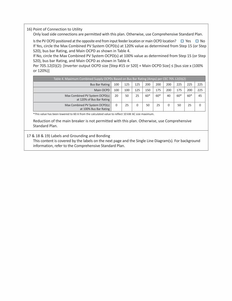
CEC Articles 690 and 705 and CRC Section R331 require the following labels or markings be installed at these components of the photovoltaic system:
EXPEDITED SOLAR PV STANDARD PLAN Central/String Inverter Systems for One and Two Family Dwellings
3
CEC Articles 690 and 705 and CRC Section R331 require the following labels or markings be installed at these components of the photovoltaic system:
WARNINGELECTRIC SHOCK HAZARD. THE DC
CONDUCTORS OF THIS PHOTOVOLTAIC SYSTEM ARE UNGROUNDED AND MAY
BE ENERGIZED
WARNINGINVERTER OUTPUT CONNECTION;
DO NOT RELOCATE THISOVERCURRENT DEVICE
CRC R331.2 and CFC 605.11.1[Marked on junction/combiner boxes
and conduit every 10’]
WARNING: PHOTOVOLTAIC POWER SOURCE
J/Box
PV SYSTEM AC DISCONNECT RATED AC OUTPUT CURRENT - ____AMPS
AC NORMAL OPERATING VOLTAGE ___VOLTS
M
AC
INVERTER
DC
WARNINGDUAL POWER SOURCES
SECOND SOURCE IS PHOTOVOLTAIC SYSTEMRATED AC OUTPUT CURRENT- ____AMPS ACNORMAL OPERATING VOLTAGE ___VOLTS
WARNINGELECTRIC SHOCK HAZARDDO NOT TOUCH TERMINALS
TERMINALS ON BOTH LINE AND LOAD SIDES MAY BE ENERGIZED IN THE
OPEN POSITION
PV SYSTEM DC DISCONNECT RATED MAX POWER-POINT CURRENT- ___ADCRATED MAX POWER-POINT VOLTAGE- ___VDC
SHORT CIRCUIT CURRENT- ___ADC MAXIMUM SYSTEM VOLTAGE- ___VDC
CEC 705.12(D)(7)[Not required if panelboard is rated not
less than sum of ampere ratings of all overcurrent devices supplying it]
CEC 690.35(F)[Only required for ungrounded systems]
CEC 690.54
CEC 690.53
CEC 690.17
CEC 690.54 & CEC 705.12(D)(4)
Code Abbreviations:California Electrical Code (CEC)California Residential Code (CRC)California Fire Code (CFC)
WARNINGELECTRIC SHOCK HAZARD
IF A GROUND FAULT IS INDICATED,NORMALLY GROUNDED CONDUCTORS
MAY BE UNGROUNDED AND ENERGIZED
CEC 690.5(C)[Normally already present on listed inverters]
Informational note: ANSI Z535.4 provides guidelines for the design of safety signs and labels for application to products. A phenolic plaque with contrasting colors between the text and background would meet the intent of the code for permanency. No type size is specified, but 20 point (3/8”) should be considered the minimum.
CEC 705.12 requires a permanent plaque or directory denoting all electric power sources on or in the premises.

Sola
r P
V S
tan
da
rd P
lan
— S
imp
lifi
ed
C
en
tra
l/St
rin
g I
nve
rter
Syst
em
s fo
r O
ne
- a
nd
Tw
o-F
am
ily
Dw
ellin
gs
D
ESC
RIP
TIO
N
SOLA
R P
V M
OD
ULE
/ ST
RIN
GD
C/D
C C
ON
VER
TER
S IN
STAL
LED
?
YES
/ N
O
(IF
YES
, STE
PS 6
& 8
REQ
UIR
ED)
SOU
RC
E C
IRC
UIT
JU
NC
TIO
N B
OX
INST
ALLE
D?:
YE
S /
NO
SEPA
RAT
E D
C D
ISC
ON
NEC
T IN
STAL
LED
?:
YES
/ N
OIN
TER
NAL
INVE
RTE
R D
C D
ISC
ON
NEC
T:
YES
/ N
OC
ENTR
AL IN
VER
TER
LOAD
CEN
TER
INST
ALLE
D?:
YE
S /
NO
PV
PR
OD
UC
TIO
N M
ETER
INST
ALLE
D?:
YE
S /
NO
*S
EPAR
ATE
AC D
ISC
ON
NEC
T IN
STAL
LED
?:
YES
/ N
OC
ON
NEC
T TO
INVE
RTE
R #
2
(USE
LIN
E D
IAG
RAM
2)
TAG
1 2 3 4 5 6 7 8 9 10
AC DCG
MAI
N S
ERVI
CE P
ANEL
67
5
CB 1
CB 1
CB 2
CB 2
31
10
MAI
N
OCP
D
G
9
PV O
CPD
M
4
___
MO
DULE
S
___
MO
DULE
S
___
MO
DULE
S
___
MO
DULE
S
AD
BC
TAG
DESCRIPTION AND CONDUCTOR TYPE
CONDUCTOR
SIZE
NUMBER OF
CONDUCTORS
CONDUIT/CABLE
TYPE
CONDUIT SIZE
A
USE-2 □ OR PV-WIRE □
EGC/GEC:
B
EGC/GEC:
C
EGC/GEC:
D
EGC/GEC:
CONDUCTOR/CONDUIT SCHEDULE
M8
CHEC
K A
BOX
FOR
WHE
THER
SYS
TEM
IS G
ROU
NDE
D O
R U
NGR
OU
NDE
D:
G
ROU
NDE
D (IN
CLU
DE G
EC)
UN
GRO
UN
DED
ENTE
R “N
/A”
WHE
RE S
UITA
BLE
FOR
WHE
N N
OT
USIN
G CO
NDU
IT O
R CA
BLE
AS P
ERM
ITTE
D BY
CO
DE
2
IF D
C/DC
CO
NVE
RTER
S AR
E US
ED, C
HECK
THE
BO
X BE
LOW
THE
CO
RRES
PON
DIN
G CO
NFI
GURA
TIO
N
PARA
LLEL
DC/
DC C
ON
VERT
ERS
ON
ON
E SO
URCE
CIR
CUIT
(FIX
ED U
NIT
VO
LTAG
E DC
/DC
CON
VERT
ERS)
DC/D
C CO
NVE
RTER
S AR
E AL
L RU
N
IN S
ERIE
S (F
IXED
SO
URCE
CIR
CUIT
VO
LTAG
E DC
/DC
CON
VERT
ERS)
+ + --
+ + --
INVE
RTE
R
DC/DC CONVERTERS
DC/DC CONVERTERS
FOR
UN
GRO
UN
DED
SYST
EMS:
- DC
OCP
D M
UST
DIS
CON
NEC
T BO
TH C
ON
DUCT
ORS
OF
EACH
SO
URC
E CI
RCU
IT- U
NGR
OU
NDE
D CO
NDU
CTO
RS M
UST
BE
IDEN
TIFI
ED P
ER 2
10.5
(C).
WHI
TE-F
INIS
HED
CON
DUCT
ORS
ARE
NO
T PE
RMIT
TED.
+ -
+ -
INVE
RTE
R
SIN
GLE
-LIN
E D
IAG
RA
M #
1 –
NO
STR
ING
S C
OM
BIN
ED P
RIO
R T
O IN
VER
TER
* Co
nsul
t with
you
r loc
al A
HJ a
nd /o
r Util
ity

Sola
r P
V S
tan
da
rd P
lan
— S
imp
lifi
ed
C
en
tra
l/St
rin
g I
nve
rter
Syst
em
s fo
r O
ne
- a
nd
Tw
o-F
am
ily
Dw
ellin
gs
D
ES
CR
IPTI
ON
S
OLA
R P
V M
OD
ULE
/ S
TRIN
GD
C/D
C C
ON
VE
RTE
RS
INS
TALL
ED
?
YE
S /
NO
(
IF Y
ES
, STE
PS
6 &
8 R
EQ
UIR
ED
)S
OU
RC
E C
IRC
UIT
JU
NC
TIO
N B
OX
INS
TALL
ED
?:
YE
S /
NO
CO
MB
INE
R B
OX
(STE
PS
11
& 1
2 R
EQ
UIR
ED
)S
EP
AR
ATE
DC
DIS
CO
NN
EC
T IN
STA
LLE
D?:
Y
ES
/ N
OIN
TER
NA
L IN
VE
RTE
R D
C D
ISC
ON
NE
CT:
Y
ES
/ N
OC
EN
TRA
L IN
VE
RTE
RLO
AD
CE
NTE
R IN
STA
LLE
D?:
Y
ES
/ N
O
PV
PR
OD
UC
TIO
N M
ETE
R IN
STA
LLE
D?:
Y
ES
/ N
O
*SE
PA
RA
TE A
C D
ISC
ON
NE
CT
INS
TALL
ED
?:
YE
S /
NO
CO
NN
EC
T TO
INV
ER
TER
#2
(U
SE
LIN
E D
IAG
RA
M 4
)
TAG
1 2 3 4 5 6 7 8 9 10 11
AC DCG
MAI
N S
ERVI
CE P
ANEL
78
6
CB 1
CB 1
CB 2
CB 2
31
11
MAI
N
OCP
D
G
10
PV O
CPD
M
5
___
MO
DULE
S
___
MO
DULE
S
___
MO
DULE
S
___
MO
DULE
S
ED
TAG
DESCRIPTION AND
CONDUCTOR TYPE
CONDUCTOR
SIZE
NUMBER OF
CONDUCTORS
CONDUIT/CABLE
TYPE
CONDUIT SIZE
A1
USE-2 □ OR PV-WIRE □
EGC/GEC:
B1
EGC/GEC:
C
EGC/GEC:
D
EGC/GEC:
E
EGC/GEC:
COMBINER CONDUCTOR/CONDUIT SCHEDULE
M9
CHEC
K A
BOX
FOR
WHE
THER
SYS
TEM
IS G
ROU
NDE
D O
R U
NG
ROU
NDE
D:
G
ROU
NDE
D (IN
CLU
DE G
EC)
UN
GRO
UN
DED
ENTE
R “N
/A”
WHE
RE S
UIT
ABLE
FO
R W
HEN
NO
T U
SIN
G CO
NDU
IT O
R CA
BLE
AS P
ERM
ITTE
D BY
CO
DE
2
IF D
C/DC
CO
NVE
RTER
S AR
E U
SED,
THE
Y AR
E RU
N IN
SER
IES
(FIX
ED S
OU
RCE
CIRC
UIT
VO
LTAG
E DC
/DC
CON
VERT
ERS)
+ + --
INV
ER
TER
DC/DC CONVERTERS
FOR
UN
GRO
UN
DED
SYST
EMS:
- DC
OCP
D M
UST
DIS
CON
NEC
T BO
TH C
ON
DUCT
ORS
OF
EACH
SO
URC
E CI
RCU
IT- U
NG
ROU
NDE
D CO
NDU
CTO
RS M
UST
BE
IDEN
TIFI
ED P
ER 2
10.5
(C).
WHI
TE-F
INIS
HED
CON
DUCT
ORS
ARE
NO
T PE
RMIT
TED .
+ -
4
B1C
A1
SIN
GLE
-LIN
E D
IAG
RA
M #
2 –
CO
MB
ININ
G S
TRIN
GS
PRIO
R T
O IN
VER
TER
___
MO
DULE
S
___
MO
DULE
S
B2A2
TAG
DESC
RIPT
ION
AN
D CO
NDU
CTO
R TY
PECO
NDU
CTO
R SI
ZEN
UMBE
R O
F CO
NDU
CTO
RSCO
NDU
IT/C
ABLE
TY
PECO
NDU
IT S
IZE
A2US
E-2
□
OR
P
V-W
IRE
□EG
C/GE
C:B2
EGC/
GEC:
NO
N-C
OM
BIN
ED S
TRIN
GS C
ON
DUCT
OR/
CON
DUIT
SCH
EDUL
E (IF
APP
LICA
BLE)
* Co
nsul
t with
you
r loc
al A
HJ a
nd /o
r Util
ity
Solar PV Standard Plan — Simplified Central/String Inverter Systems for One- and Two-Family Dwellings
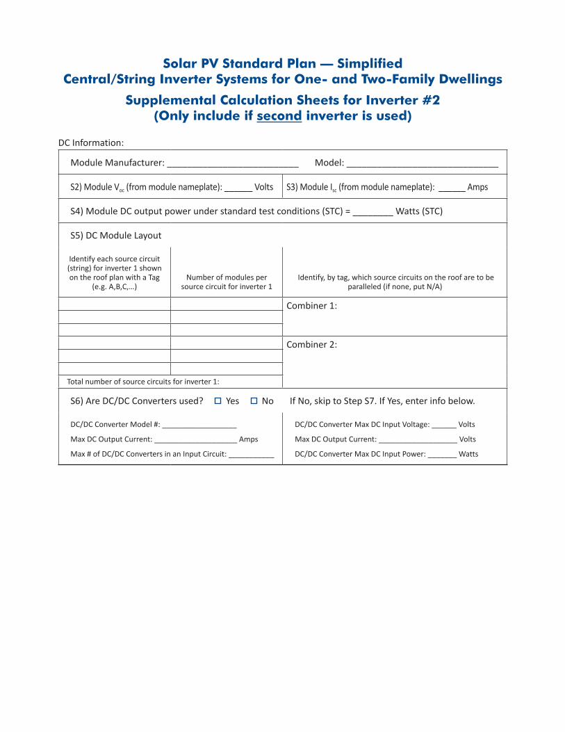
Supplemental Calculation Sheets for Inverter #2 (Only include if second inverter is used)
DC Information:
Module Manufacturer: __________________________ Model: ______________________________
S2) Module Voc (from module nameplate): ______ Volts S3) Module Isc (from module nameplate): ______ Amps
S4) Module DC output power under standard test conditions (STC) = ________ Watts (STC)
S5) DC Module Layout
Identify each source circuit (string) for inverter 1 shown on the roof plan with a Tag
(e.g. A,B,C,…)Number of modules per
source circuit for inverter 1 Identify, by tag, which source circuits on the roof are to be
paralleled (if none, put N/A)
Combiner 1:
Combiner 2:
Total number of source circuits for inverter 1:
S6) Are DC/DC Converters used? Yes No If No, skip to Step S7. If Yes, enter info below.
DC/DC Converter Model #: __________________
Max DC Output Current: ____________________ Amps
Max # of DC/DC Converters in an Input Circuit: ___________
DC/DC Converter Max DC Input Voltage: ______ Volts
Max DC Output Current: ___________________ Volts
DC/DC Converter Max DC Input Power: _______ Watts
D
ES
CR
IPTI
ON
S
OLA
R P
V M
OD
ULE
/ S
TRIN
GD
C/D
C C
ON
VE
RTE
RS
INS
TALL
ED
?
YE
S /
NO
(
IF Y
ES
, STE
PS
6 &
8 R
EQ
UIR
ED
)S
OU
RC
E C
IRC
UIT
JU
NC
TIO
N B
OX
INS
TALL
ED
?:
YE
S /
NO
CO
MB
INE
R B
OX
(STE
PS
11
& 1
2 R
EQ
UIR
ED
)S
EP
AR
ATE
DC
DIS
CO
NN
EC
T IN
STA
LLE
D?:
Y
ES
/ N
OIN
TER
NA
L IN
VE
RTE
R D
C D
ISC
ON
NE
CT:
Y
ES
/ N
OC
EN
TRA
L IN
VE
RTE
RLO
AD
CE
NTE
R IN
STA
LLE
D?:
Y
ES
/ N
O
PV
PR
OD
UC
TIO
N M
ETE
R IN
STA
LLE
D?:
Y
ES
/ N
O
*SE
PA
RA
TE A
C D
ISC
ON
NE
CT
INS
TALL
ED
?:
YE
S /
NO
CO
NN
EC
T TO
INV
ER
TER
#2
(U
SE
LIN
E D
IAG
RA
M 4
)
TAG
1 2 3 4 5 6 7 8 9 10 11
AC DCG
MAI
N S
ERVI
CE P
ANEL
78
6
CB 1
CB 1
CB 2
CB 2
31
11
MAI
N
OCP
D
G
10
PV O
CPD
M
5
___
MO
DULE
S
___
MO
DULE
S
___
MO
DULE
S
___
MO
DULE
S
ED
TAG
DESCRIPTION AND
CONDUCTOR TYPE
CONDUCTOR
SIZE
NUMBER OF
CONDUCTORS
CONDUIT/CABLE
TYPE
CONDUIT SIZE
A1
USE-2 □ OR PV-WIRE □
EGC/GEC:
B1
EGC/GEC:
C
EGC/GEC:
D
EGC/GEC:
E
EGC/GEC:
COMBINER CONDUCTOR/CONDUIT SCHEDULE
M9
CHEC
K A
BOX
FOR
WHE
THER
SYS
TEM
IS G
ROU
NDE
D O
R U
NG
ROU
NDE
D:
G
ROU
NDE
D ( IN
CLU
DE G
EC)
UN
GRO
UN
DED
ENTE
R “N
/A”
WHE
RE S
UIT
ABLE
FO
R W
HEN
NO
T U
SIN
G CO
NDU
IT O
R CA
BLE
AS P
ERM
ITTE
D BY
CO
DE
2
IF D
C/DC
CO
NVE
RTER
S AR
E U
SED,
THE
Y AR
E RU
N IN
SER
IES
(FIX
ED S
OU
RCE
CIRC
UIT
VO
LTAG
E DC
/DC
CON
VERT
ERS)
+ + --
INV
ER
TER
DC/DC CONVERTERS
FOR
UN
GRO
UN
DED
SYST
EMS:
- DC
OCP
D M
UST
DIS
CON
NEC
T BO
TH C
ON
DUCT
ORS
OF
EACH
SO
URC
E CI
RCU
IT- U
NG
ROU
NDE
D CO
NDU
CTO
RS M
UST
BE
IDEN
TIFI
ED P
ER 2
10.5
(C).
WHI
TE-F
INIS
HED
CON
DUCT
ORS
ARE
NO
T PE
RMIT
TED.
+ -
4
B1C
A1
SIN
GLE
-LIN
E D
IAG
RA
M #
2 –
CO
MB
ININ
G S
TRIN
GS
PRIO
R T
O IN
VER
TER
___
MO
DULE
S
___
MO
DULE
S
B2A2
TAG
DESC
RIPT
ION
AN
D CO
NDU
CTO
R TY
PECO
NDU
CTO
R SI
ZEN
UMBE
R O
F CO
NDU
CTO
RSCO
NDU
IT/C
ABLE
TY
PECO
NDU
IT S
IZE
A2US
E-2
□
OR
P
V-W
IRE
□EG
C/GE
C:B2
EGC/
GEC:
NO
N-C
OM
BIN
ED S
TRIN
GS C
ON
DUCT
OR/
CON
DUIT
SCH
EDUL
E (IF
APP
LICA
BLE)
* Co
nsul
t with
you
r loc
al A
HJ a
nd /o
r Util
ity
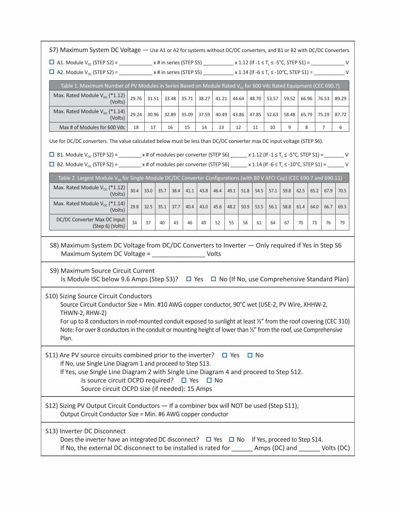
S7) Maximum System DC Voltage — Use A1 or A2 for systems without DC/DC converters, and B1 or B2 with DC/DC Converters.
A1. Module VOC (STEP S2) = ____________ x # in series (STEP S5) ___________ x 1.12 (If -1 ≤ TL ≤ -5°C, STEP S1) = ____________ V
A2. Module VOC (STEP S2) = ____________ x # in series (STEP S5) ___________ x 1.14 (If -6 ≤ TL ≤ -10°C, STEP S1) = ___________ V
Table 1. Maximum Number of PV Modules in Series Based on Module Rated VOC for 600 Vdc Rated Equipment (CEC 690.7)
Max. Rated Module VOC (*1.12) (Volts) 29.76 31.51 33.48 35.71 38.27 41.21 44.64 48.70 53.57 59.52 66.96 76.53 89.29
Max. Rated Module VOC (*1.14) (Volts) 29.24 30.96 32.89 35.09 37.59 40.49 43.86 47.85 52.63 58.48 65.79 75.19 87.72
Max # of Modules for 600 Vdc 18 17 16 15 14 13 12 11 10 9 8 7 6
Use for DC/DC converters. The value calculated below must be less than DC/DC converter max DC input voltage (STEP S6).
B1. Module VOC (STEP S2) = ________ x # of modules per converter (STEP S6) ______ x 1.12 (If -1 ≤ TL ≤ -5°C, STEP S1) = _______ V
B2. Module VOC (STEP S2) = ________ x # of modules per converter (STEP S6) ______ x 1.14 (If -6 ≤ TL ≤ -10°C, STEP S1) = ______ V
Table 2. Largest Module VOC for Single-Module DC/DC Converter Configurations (with 80 V AFCI Cap) (CEC 690.7 and 690.11)
Max. Rated Module VOC (*1.12) (Volts) 30.4 33.0 35.7 38.4 41.1 43.8 46.4 49.1 51.8 54.5 57.1 59.8 62.5 65.2 67.9 70.5
Max. Rated Module VOC (*1.14) (Volts) 29.8 32.5 35.1 37.7 40.4 43.0 45.6 48.2 50.9 53.5 56.1 58.8 61.4 64.0 66.7 69.3
DC/DC Converter Max DC Input (Step 6) (Volts) 34 37 40 43 46 49 52 55 58 61 64 67 70 73 76 79
S8) Maximum System DC Voltage from DC/DC Converters to Inverter — Only required if Yes in Step S6 Maximum System DC Voltage = _______________ Volts
S9) Maximum Source Circuit Current Is Module ISC below 9.6 Amps (Step S3)? Yes No (If No, use Comprehensive Standard Plan)
S10) Sizing Source Circuit ConductorsSource Circuit Conductor Size = Min. #10 AWG copper conductor, 90°C wet (USE-2, PV Wire, XHHW-2, THWN-2, RHW-2) For up to 8 conductors in roof-mounted conduit exposed to sunlight at least ½” from the roof covering (CEC 310) Note: For over 8 conductors in the conduit or mounting height of lower than ½” from the roof, use Comprehensive Plan.
S11) Are PV source circuits combined prior to the inverter? Yes NoIf No, use Single Line Diagram 1 and proceed to Step S13. If Yes, use Single Line Diagram 2 with Single Line Diagram 4 and proceed to Step S12. Is source circuit OCPD required? Yes No Source circuit OCPD size (if needed): 15 Amps
S12) Sizing PV Output Circuit Conductors — If a combiner box will NOT be used (Step S11),Output Circuit Conductor Size = Min. #6 AWG copper conductor
S13) Inverter DC DisconnectDoes the inverter have an integrated DC disconnect? Yes No If Yes, proceed to Step S14. If No, the external DC disconnect to be installed is rated for ______ Amps (DC) and ______ Volts (DC)

S14) Inverter InformationManufacturer: ______________________________ Model: _______________________________Max. Continuous AC Output Current Rating: _______ Amps Integrated DC Arc-Fault Circuit Protection? Yes No (If No is selected, Comprehensive Standard Plan) Grounded or Ungrounded System? Grounded Ungrounded
AC Information:
S15) Sizing Inverter Output Circuit Conductors and OCPDInverter Output OCPD rating = ______ Amps (Table 3) Inverter Output Circuit Conductor Size = ______ AWG (Table 3)
Table 3. Minimum Inverter Output OCPD and Circuit Conductor Size
Inverter Continuous Output Current Rating (Amps) (Step 14) 12 16 20 24 28 32 36 40 48
Minimum OCPD Size (Amps) 15 20 25 30 35 40 45 50 60
Minimum Conductor Size (AWG, 75°C, Copper) 14 12 10 10 8 8 6 6 6
Load Center Calculations (Omit if a load center will not be installed for PV OCPDs)
S20) Load Center Output:Calculate the sum of the maximum AC outputs from each inverter.Inverter #1 Max Continuous AC Output Current Rating [STEP S14] _______ × 1.25 = _______ AmpsInverter #2 Max Continuous AC Output Current Rating [STEP S14] _______ × 1.25 = _______ AmpsTotal inverter currents connected to load center (sum of above) = _______ Amps
Conductor Size: ______ AWG Overcurrent Protection Device: ______ AmpsLoad center bus bar rating: ______ Amps The sum of the ampere ratings of overcurrent devices in circuits supplying power to a bus bar or conductor shall not exceed 120 percent of the rating of the bus bar or conductor.

Sola
r P
V S
tan
da
rd P
lan
— S
imp
lifi
ed
C
en
tra
l/St
rin
g I
nve
rter
Syst
em
s fo
r O
ne
- a
nd
Tw
o-F
am
ily
Dw
ellin
gs
D
ES
CR
IPTI
ON
S
OLA
R P
V M
OD
ULE
/ S
TRIN
GD
C/D
C C
ON
VE
RTE
RS
INS
TALL
ED
?
YE
S /
NO
(
IF Y
ES
, STE
PS
6 &
8 R
EQ
UIR
ED
)S
OU
RC
E C
IRC
UIT
JU
NC
TIO
N B
OX
INS
TALL
ED
?:
YE
S /
NO
SE
PA
RA
TE D
C D
ISC
ON
NE
CT
INS
TALL
ED
?:
YE
S /
NO
INTE
RN
AL
INV
ER
TER
DC
DIS
CO
NN
EC
T:
YE
S /
NO
CE
NTR
AL
INV
ER
TER
*SE
PA
RA
TE A
C D
ISC
ON
NE
CT
INS
TALL
ED
?:
YE
S /
NO
TO L
OA
D C
EN
TER
ON
LIN
E D
IAG
RA
M 1
TAG
1 2 3 4 5 6 7 8
AC DC
65
31
4
___
MO
DULE
S
___
MO
DULE
S
___
MO
DULE
S
___
MO
DULE
S
AB
C
TAG
DESCRIPTION AND CONDUCTOR TYPE
CONDUCTOR
SIZE
NUMBER OF
CONDUCTORS
CONDUIT/CABLE
TYPE
CONDUIT SIZE
A
USE-2 □ OR PV-WIRE □
EGC/EGC:
B
EGC/EGC:
C
EGC/EGC:
CONDUCTOR/CONDUIT SCHEDULE
CHEC
K A
BOX
FOR
WHE
THER
SYS
TEM
IS G
ROU
NDE
D O
R U
NG
ROU
NDE
D:
G
ROU
NDE
D (IN
CLU
DE G
EC)
UN
GRO
UN
DED
ENTE
R “N
/A”
WHE
RE S
UIT
ABLE
FO
R W
HEN
N
OT
USI
NG
CON
DUIT
OR
CABL
E AS
PE
RMIT
TED
BY C
ODE
2
IF D
C/DC
CO
NVE
RTER
S AR
E U
SED ,
CHE
CK T
HE B
OX
BELO
W T
HE C
ORR
ESPO
NDI
NG
CON
FIGU
RATI
ON
PARA
LLEL
DC/
DC C
ON
VERT
ERS
ON
ON
E SO
URC
E CI
RCU
IT (F
IXED
UN
IT V
OLT
AGE
DC/D
C CO
NVE
RTER
S)
DC/D
C CO
NVE
RTER
S AR
E AL
L RU
N
IN S
ERIE
S (F
IXED
SO
URC
E CI
RCU
IT
VOLT
AGE
DC/D
C CO
NVE
RTER
S)
+ + --
+ + --
INV
ER
TER
DC/DC CONVERTERS
DC/DC CONVERTERS
FOR
UN
GRO
UN
DED
SYST
EMS:
- DC
OCP
D M
UST
DIS
CON
NEC
T BO
TH C
ON
DUCT
ORS
OF
EACH
SO
URC
E CI
RCU
IT- U
NG
ROU
NDE
D CO
NDU
CTO
RS M
UST
BE
IDEN
TIFI
ED P
ER 2
10.5
(C).
WHI
TE-F
INIS
HED
CON
DUCT
ORS
ARE
NO
T PE
RMIT
TED.
+ -
+ -
INV
ER
TER
7
8
SIN
GLE
-LIN
E D
IAG
RA
M #
3 –
AD
DIT
ION
AL
INVE
RTE
R F
OR
DIA
GR
AM
#1
INVE
RTER
# 2
* Co
nsul
t with
you
r loc
al A
HJ a
nd /o
r Util
ity
Sola
r P
V S
tan
da
rd P
lan
— S
imp
lifi
ed
C
en
tra
l/St
rin
g I
nve
rter
Syst
em
s fo
r O
ne
- a
nd
Tw
o-F
am
ily
Dw
ellin
gs
D
ES
CR
IPTI
ON
S
OLA
R P
V M
OD
ULE
/ S
TRIN
GD
C/D
C C
ON
VE
RTE
RS
INS
TALL
ED
?
YE
S /
NO
(
IF Y
ES
, STE
PS
6 &
8 R
EQ
UIR
ED
)S
OU
RC
E C
IRC
UIT
JU
NC
TIO
N B
OX
INS
TALL
ED
?:
YE
S /
NO
SE
PA
RA
TE D
C D
ISC
ON
NE
CT
INS
TALL
ED
?:
YE
S /
NO
INTE
RN
AL
INV
ER
TER
DC
DIS
CO
NN
EC
T:
YE
S /
NO
CE
NTR
AL
INV
ER
TER
*SE
PA
RA
TE A
C D
ISC
ON
NE
CT
INS
TALL
ED
?:
YE
S /
NO
TO L
OA
D C
EN
TER
ON
LIN
E D
IAG
RA
M 1
TAG
1 2 3 4 5 6 7 8
AC DC
65
31
4
___
MO
DULE
S
___
MO
DULE
S
___
MO
DULE
S
___
MO
DULE
S
AB
C
TAG
DESCRIPTION AND CONDUCTOR TYPE
CONDUCTOR
SIZE
NUMBER OF
CONDUCTORS
CONDUIT/CABLE
TYPE
CONDUIT SIZE
A
USE-2 □ OR PV-WIRE □
EGC/EGC:
B
EGC/EGC:
C
EGC/EGC:
CONDUCTOR/CONDUIT SCHEDULE
CHEC
K A
BOX
FOR
WHE
THER
SYS
TEM
IS G
ROU
NDE
D O
R U
NG
ROU
NDE
D:
G
ROU
NDE
D (IN
CLU
DE G
EC)
UN
GRO
UN
DED
ENTE
R “N
/A”
WHE
RE S
UIT
ABLE
FO
R W
HEN
N
OT
USI
NG
CON
DUIT
OR
CABL
E AS
PE
RMIT
TED
BY C
ODE
2
IF D
C/DC
CO
NVE
RTER
S AR
E U
SED,
CHE
CK T
HE B
OX
BELO
W T
HE C
ORR
ESPO
NDI
NG
CON
FIGU
RATI
ON
PARA
LLEL
DC/
DC C
ON
VERT
ERS
ON
ON
E SO
URC
E CI
RCU
IT (F
IXED
UN
IT V
OLT
AGE
DC/D
C CO
NVE
RTER
S)
DC/D
C CO
NVE
RTER
S AR
E AL
L RU
N
IN S
ERIE
S (F
IXED
SO
URC
E CI
RCU
IT
VOLT
AGE
DC/D
C CO
NVE
RTER
S)
+ + --
+ + --
INV
ER
TER
DC/DC CONVERTERS
DC/DC CONVERTERS
FOR
UN
GRO
UN
DED
SYST
EMS:
- DC
OCP
D M
UST
DIS
CON
NEC
T BO
TH C
ON
DUCT
ORS
OF
EACH
SO
URC
E CI
RCU
IT- U
NG
ROU
NDE
D CO
NDU
CTO
RS M
UST
BE
IDEN
TIFI
ED P
ER 2
10.5
(C).
WHI
TE-F
INIS
HED
CON
DUCT
ORS
ARE
NO
T PE
RMIT
TED.
+ -
+ -
INV
ER
TER
7
8
SIN
GLE
-LIN
E D
IAG
RA
M #
3 –
AD
DIT
ION
AL
INVE
RTE
R F
OR
DIA
GR
AM
#1
INVE
RTER
# 2
* Co
nsul
t with
you
r loc
al A
HJ a
nd /o
r Util
ity
D
ES
CR
IPTI
ON
S
OLA
R P
V M
OD
ULE
/ S
TRIN
GD
C/D
C C
ON
VE
RTE
RS
INS
TALL
ED
?
YE
S /
NO
(
IF Y
ES
, STE
PS
6 &
8 R
EQ
UIR
ED
)S
OU
RC
E C
IRC
UIT
JU
NC
TIO
N B
OX
INS
TALL
ED
?:
YE
S /
NO
CO
MB
INE
R B
OX
(STE
PS
11
& 1
2 R
EQ
UIR
ED
)S
EP
AR
ATE
DC
DIS
CO
NN
EC
T IN
STA
LLE
D?:
Y
ES
/ N
OIN
TER
NA
L IN
VE
RTE
R D
C D
ISC
ON
NE
CT:
Y
ES
/ N
OC
EN
TRA
L IN
VE
RTE
R*S
EP
AR
ATE
AC
DIS
CO
NN
EC
T IN
STA
LLE
D?:
Y
ES
/ N
O
TO L
OA
D C
EN
TER
ON
LIN
E D
IAG
RA
M 3
TAG
1 2 3 4 5 6 7 8 9
AC DC
76
31
5
___
MO
DULE
S
___
MO
DULE
S
___
MO
DULE
S
___
MO
DULE
S
D
TAG
DESCRIPTION AND
CONDUCTOR TYPE
CONDUCTOR
SIZE
NUMBER OF
CONDUCTORS
CONDUIT/CABLE
TYPE
CONDUIT SIZE
A1
USE-2 □ OR PV-WIRE □
EGC/GEC:
B1
EGC/GEC:
C
EGC/GEC:
D
EGC/GEC:
COMBINER CONDUCTOR/CONDUIT SCHEDULE
CHEC
K A
BOX
FOR
WHE
THER
SYS
TEM
IS G
ROU
NDE
D O
R U
NG
ROU
NDE
D:
G
ROU
NDE
D (IN
CLU
DE G
EC)
UN
GRO
UN
DED
ENTE
R “N
/A”
WHE
RE S
UIT
ABLE
FO
R W
HEN
NO
T U
SIN
G CO
NDU
IT O
R CA
BLE
AS P
ERM
ITTE
D BY
CO
DE
2
IF D
C/DC
CO
NVE
RTER
S AR
E U
SED,
THE
Y AR
E RU
N IN
SER
IES
(FIX
ED S
OU
RCE
CIRC
UIT
VO
LTAG
E DC
/DC
CON
VERT
ERS)
+ + --
INV
ER
TER
DC/DC CONVERTERS
FOR
UN
GRO
UN
DED
SYST
EMS:
- DC
OCP
D M
UST
DIS
CON
NEC
T BO
TH C
ON
DUCT
ORS
OF
EACH
SO
URC
E CI
RCU
IT- U
NG
ROU
NDE
D CO
NDU
CTO
RS M
UST
BE
IDEN
TIFI
ED P
ER 2
10.5
(C).
WHI
TE-F
INIS
HED
CON
DUCT
ORS
ARE
NO
T PE
RMIT
TED .
+ -
4
B1C
A1
8
9
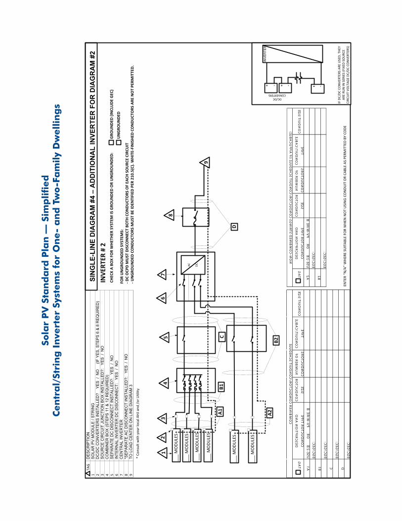
SIN
GLE
- LIN
E D
IAG
RA
M #
4 –
AD
DIT
ION
AL
INVE
RTE
R F
OR
DIA
GR
AM
#2
INVE
RTER
# 2
TAG
DESCRIPTION AND
CONDUCTOR TYPE
CONDUCTOR
SIZE
NUMBER OF
CONDUCTORS
CONDUIT/CABLE
TYPE
CONDUIT SIZE
A2
USE-2 □ OR PV-WIRE □
EGC/GEC:
B2
EGC/GEC:
NON-COMBINED STRINGS CONDUCTOR/CONDUIT SCHEDULE (IF APPLICABLE)
___
MO
DULE
S
___
MO
DULE
S
B2A2
* Co
nsul
t with
you
r loc
al A
HJ a
nd /o
r Util
ity

SOLA
R P
V ST
AN
DA
RD
PLA
NR
oof L
ayou
t Dia
gram
for O
ne- a
nd T
wo-
Fam
ily D
wel
lings
Item
s re
quire
d: ro
of la
yout
of a
ll pa
nels
, mod
ules
, cle
ar a
cces
s pa
thw
ays
and
appr
oxim
ate
loca
tions
of e
lect
rical
dis
conn
ectin
g m
eans
and
roof
acc
ess
poin
ts.