Embed Size (px)
Citation preview

SOLAR OPTIONS FOR LANDFILL COVER SYSTEMS
March 2020

___AGENDA
• INTRODUCTIONS & EXPERIENCE
• REGULATORY REQUIREMENTS & TIMELINE
• SOLAR ARRAY DEPLOYMENT OPTIONS & CONSIDERATIONS
• BURIED SYSTEMS FOR SOIL COMPONENT CAPS AND ADJACENT LANDS
• BALLASTED SYSTEMS FOR GOESYNTHETIC & SOIL COMPONENT CAPS
• MOUNTING SYSTEMS FOR FULL GEOSYNTHETIC CAPS
2

INTRODUCTIONS & EXPERIENCE
___
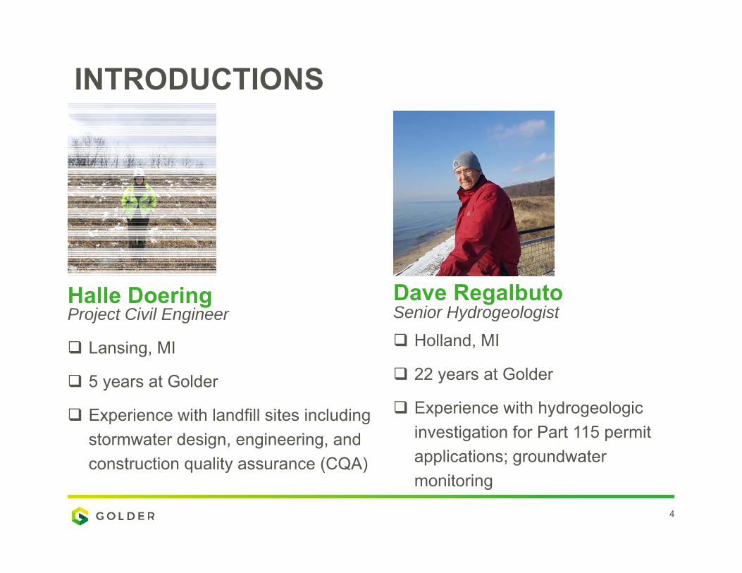
4
Lansing, MI
5 years at Golder
Experience with landfill sites including stormwater design, engineering, and construction quality assurance (CQA)
Halle Doering Project Civil Engineer
Holland, MI
22 years at Golder
Experience with hydrogeologic investigation for Part 115 permit applications; groundwater monitoring
Dave RegalbutoSenior Hydrogeologist
INTRODUCTIONS

___
5
RECENT EXAMPLES OF SOLAR AT LANDFILLSCLOSED SITE
• East Lansing Solar Park: occupies NW portion of Burcham Park, East Lansing, operational in 2018. Site of a closed/capped but unlined landfill with protective soil cover. 1,000-panel solar array –ballasted type support; no cap penetration of solar panel mounts.

___
6
RECENT EXAMPLES OF SOLAR AT LANDFILLSSITES PLANNING CLOSURE PRESENTLY
• Mississippi CCR Landfill - to be permitted and constructed in 2020 with full geosynthetics including solar panels on ClosureTurf®
• Type III Landfills – currently facilities in northern and southern MI are considering solar applications both on and adjacent to the landfill footprint

___
7
RECENT EXAMPLES OF SOLAR AT LANDFILLSFUTURE SITES
• Lansing, MI Type III Landfill - permitted in Michigan for the use of final cover in 2019 with the use of ClosureTurf® and solar panels
• Grand Rapids, MI MSW Incinerator Ash Landfill - permitted in Michigan for the use of final cover in 2017 with the use of ClosureTurf® and considering solar panels

REGULATORY REQUIREMENTS & TIMELINE

___
9
REGULATORY FRAMEWORK
• Liner penetration: likely not an option, but design to prevent preferential CH4 and infiltrations pathways
• Load requirements on liner (~5psi – 720 psf)• Cable height above the liner– follow local
electrical codes, some systems have integrated wire, different options available
• Equipment used for installation of panels on liner
• Impacts to landfill after lifetime of solar system expires
• Settlement issues • Financial assurance – additional maintenance
costs• Wind and snow loads • Stormwater management • Typical post closure inspections
• Stormwater management • Closure and post closure • Permit conditions • Penetrations of the landfill
cap • Site preparation and grading • Community involvement and
transparency • Regulatory requirements
should be part of a feasibility study or conceptual design
E PA R E Q U I R E M E N T SE G L E C O N S I D E R AT I O N S

___
10
TIMELINEC L O S E D S I T E S
• 3 months engineering design, collaboration with solar manufacturer
• 1 - 5 Months for EGLE review of permit Submitted as modification – Part 115-18 (liner penetration) – 5 months
(150 days) Submitted as upgrade/improvement
• Can be approved by local regulator• Need to be clear and prove that it is an actual improvement with Part 115
rules • Prove on cap solar systems don’t damage liner • No public notice required
• Design- build option or additional ~2 months for design-bid–build • Total: 4 -10 months dependent on system and design-build
selections
___
11
TIMELINES I T E S P L A N N I N G C L O S U R E
• 3 months engineering design, collaboration with solar manufacturer
• 5 Months for EGLE review of permit • Submitted as part of landfill closure plan and permit –Part 115-7, 5
months (150 days)• Design- build option or additional ~2 months for design-bid–build • Total 8 -10 Months dependent on design-build selections
S I T E S R E Q U I R I N G F I L L A N D G R A D I N G • Sites vary on closure timeline dependent on quantity of fill and
grading required to meet closure grades

SOLAR ARRAY DEPLOYMENT OPTIONS & CONSIDERATIONS
___
13
ACCEPTABLE SLOPES :
S O U T H FA C I N G • Optimal production on south facing slopes, greater time exposed to
sunlight • Closure plans can incorporate grading necessary to optimize solar
production• Slope orientations outside of +/- 20-30deg from due south typically result
in lower annual energy production, these slopes are typically adjusted through grading or not considered useable
• Option to install longer legs on back side of panels to adjust tilt to south, locally manufactured as needed
2 - 5 %• Less dense, more space needed between panels (~5-10 feet)• Typically ballasted system • Minimal slopes reduce rainfall infiltration through the cap, reduce erosion,
and avoid ponding
FROM: EPA, https://www.epa.gov/sites/production/files/2015-03/documents/best_practices_siting_solar_photovoltaic_final.pdf

___
14
ACCEPTABLE SLOPES :2 5 - 3 3 %
• Denser panels and less space needed • Installation and servicing more difficult on steeper slopes • Steeper slopes generally require lighter-weight solar arrays and heavier
foundations to anchor the system (not ideal for ballasted systems) • Foundation/anchoring system more challenging • Higher wind loads • Increased erosion • Best practices using fix tilt mounted systems • PV integrated geomembrane (rail system with closure turf)• Higher costs associated with difficulties installing and manufacturing for
steeper slopes
FROM: EPA, https://www.epa.gov/sites/production/files/2015-03/documents/best_practices_siting_solar_photovoltaic_final.pdf
___
15
OTHER CONSIDERATIONS:W I R I N G F O R E L E C T R I C A L C O N N E C T I O N
• Wiring connecting arrays to inverters and inverters to the point of interconnection
• Generally run as direct burial through trenches• In landfills, wiring may be required to run through above-ground conduit
due to restrictions with cap penetrations or other concerns
S Y S T E M M O N I TO R I N G • Consistent monitoring systems with traditional green field sites.
FROM: EPA, https://www.epa.gov/sites/production/files/2015-03/documents/best_practices_siting_solar_photovoltaic_final.pdf
___
16
MAINTENANCE• Routine operations and maintenance of photovoltaic systems are usually
minimal in cost, ranging from $10-15/kW on an annual basis • Following installation of solar panel system, the solar system operation,
maintenance, and monitoring can be intergraded with the landfill. • Panel washing and water management plan or Natural Cleansing• ClosureTurf® does not require mowing around the solar panels
FROM: EPA, https://www.epa.gov/sites/production/files/2015-03/documents/best_practices_siting_solar_photovoltaic_final.pdf
OTHER CONSIDERATIONS (Cont.):

BURIED SYSTEMS FOR SOIL COMPONENT CAPS AND ADJACENT LANDS
___
18
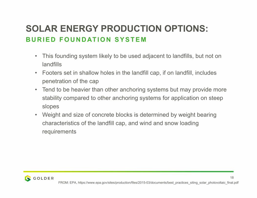
SOLAR ENERGY PRODUCTION OPTIONS:B U R I E D F O U N D AT I O N S Y S T E M
• This founding system likely to be used adjacent to landfills, but not on landfills
• Footers set in shallow holes in the landfill cap, if on landfill, includes penetration of the cap
• Tend to be heavier than other anchoring systems but may provide more stability compared to other anchoring systems for application on steep slopes
• Weight and size of concrete blocks is determined by weight bearing characteristics of the landfill cap, and wind and snow loading requirements
FROM: EPA, https://www.epa.gov/sites/production/files/2015-03/documents/best_practices_siting_solar_photovoltaic_final.pdf
___
19
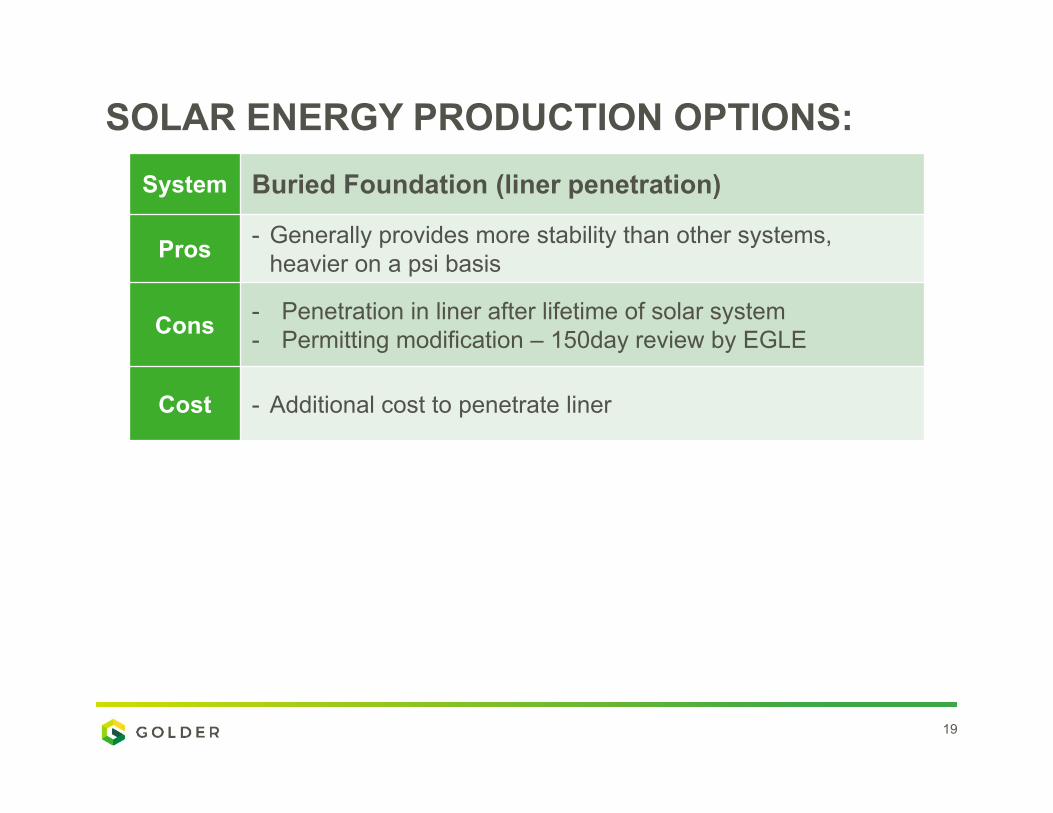
SOLAR ENERGY PRODUCTION OPTIONS:System Buried Foundation (liner penetration)
Pros - Generally provides more stability than other systems, heavier on a psi basis
Cons - Penetration in liner after lifetime of solar system- Permitting modification – 150day review by EGLE
Cost - Additional cost to penetrate liner

___
20
BURIED FOUNDATION SYSTEM
BALLASTED SYSTEMS FOR GEOSYNTHETIC & SOIL COMPONENT CAPS
___
22
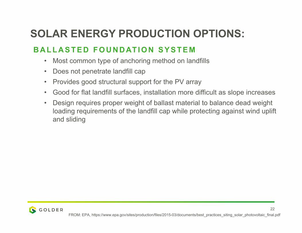
SOLAR ENERGY PRODUCTION OPTIONS:B A L L A S T E D F O U N D AT I O N S Y S T E M
• Most common type of anchoring method on landfills • Does not penetrate landfill cap • Provides good structural support for the PV array • Good for flat landfill surfaces, installation more difficult as slope increases • Design requires proper weight of ballast material to balance dead weight
loading requirements of the landfill cap while protecting against wind uplift and sliding
FROM: EPA, https://www.epa.gov/sites/production/files/2015-03/documents/best_practices_siting_solar_photovoltaic_final.pdf

___
23
SOLAR ENERGY PRODUCTION OPTIONS:System Ballasted Foundation system (above liner)
Pros
- No penetration to liner system - No damage to liner after lifetime of solar- Permitting Improvement – local regulator approval only
needed - minimal site prep or disturbance to the vegetative cover- Installed quickly- Good structural support for the PV array
Cons - Difficult installation on steeper slopes
Cost- Increasing number of manufacturers are offering pre-
packaged ballast and racking solutions that are designed for site specific conditions

___
24
BALLASTED SYSTEMS
Partners: LBWL, City of East Lansing, Michigan Energy Options, Renewable Energy Evolution
3 acres; 1000 panels; 144 lessees
465,000 kWh annually (60 homes)
B U R C H A M PA R K L A N D F I L L – E A S T L A N S I N G
2016: Conceptual design; community roll-out
2017: Engineering design; EGLE approval
2018: Construction; full operation 12-28-2018
___
25
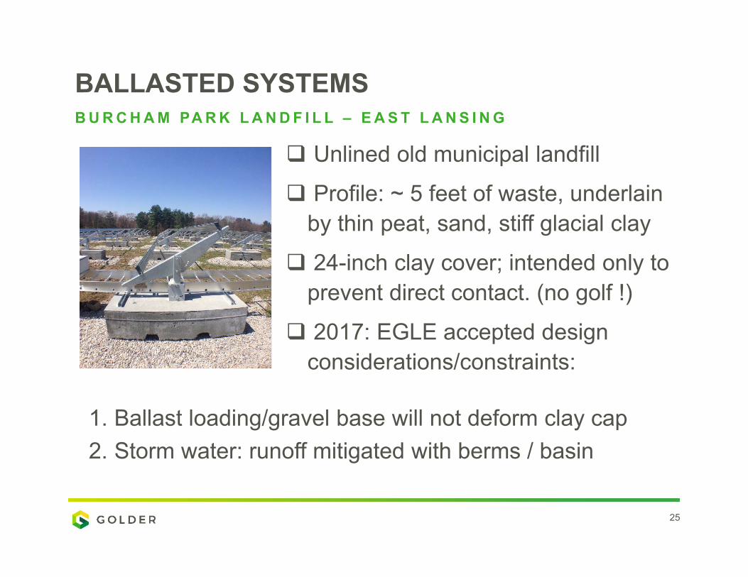
BALLASTED SYSTEMS
Unlined old municipal landfill
Profile: ~ 5 feet of waste, underlain by thin peat, sand, stiff glacial clay
24-inch clay cover; intended only to prevent direct contact. (no golf !)
2017: EGLE accepted design considerations/constraints:
B U R C H A M PA R K L A N D F I L L – E A S T L A N S I N G
1. Ballast loading/gravel base will not deform clay cap2. Storm water: runoff mitigated with berms / basin
___
26
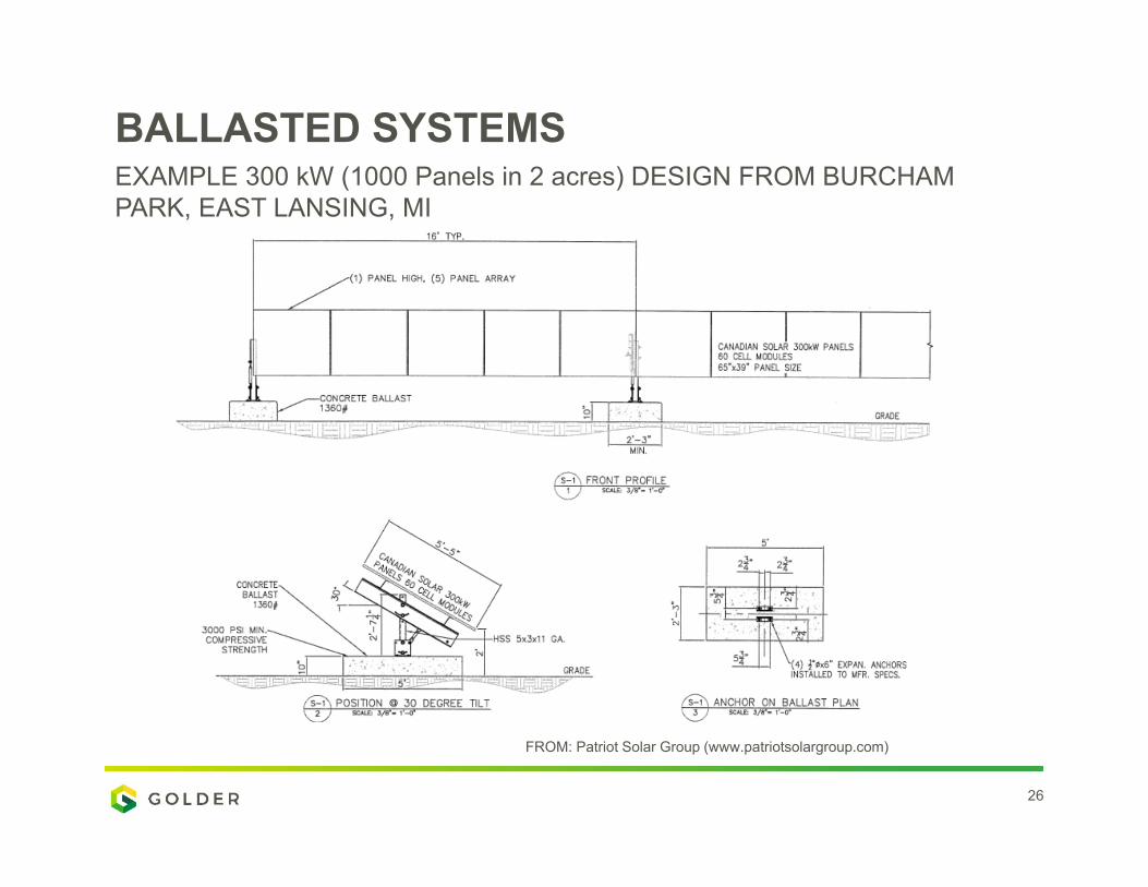
BALLASTED SYSTEMSEXAMPLE 300 kW (1000 Panels in 2 acres) DESIGN FROM BURCHAM PARK, EAST LANSING, MI
FROM: Patriot Solar Group (www.patriotsolargroup.com)

___
27
BALLASTED SYSTEMSEXAMPLE DESIGN FROM BURCHAM PARK, EAST LANSING, MI
FROM: Patriot Solar Group (www.patriotsolargroup.com)
Advantages: No cap penetrations, ash landfills see less settlement than MSW, more readily available, many projects in the Midwest/northeast.
Disadvantages: More area needed per MW, wind loads, slopes (~5% max.), maintenance.

___
28
BALLASTED SYSTEMSEXAMPLE ON CAP LANDFILL PROJECTS - MASSACHUSETTS
FROM: Patriot Solar Group (www.patriotsolargroup.com)
Edison Landfill, 7.8 MW, 90 mph wind and
50 psf snow load
North Carver Landfill, 1.77 MW, 3 high Ballasted
ground mount

MOUNTING SYSTEMS FOR FULL GEOSYNTHETIC CAPS

___
30
SOLAR ENERGY PRODUCTION OPTIONS:A LT E R N AT I V E F I N A L C O V E R O P T I O N S
• Alternative final cover can be installed with ballasted foundation or rail systems
• Rail system has higher density of panels therefore greater production per acre
• Rail system has easier and faster installation • Rail system can be used on slopes greater than 5%
FROM: EPA, https://www.epa.gov/sites/production/files/2015-03/documents/best_practices_siting_solar_photovoltaic_final.pdf
___
31
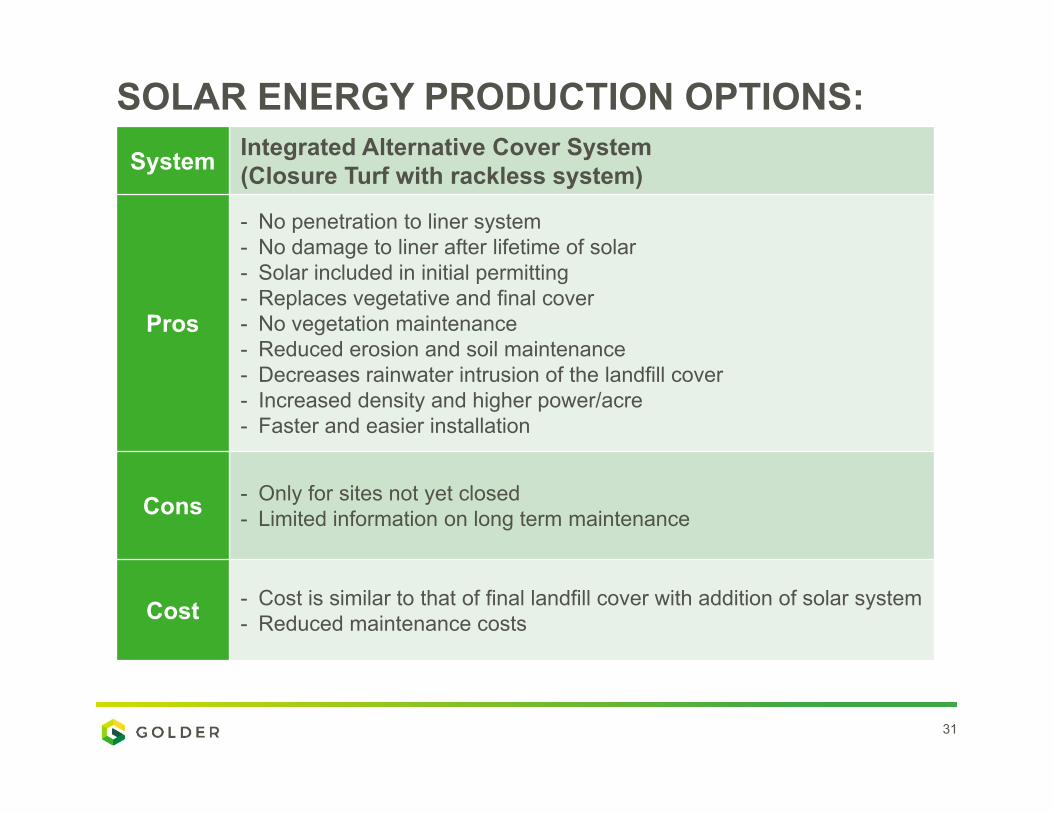
SOLAR ENERGY PRODUCTION OPTIONS:System Integrated Alternative Cover System
(Closure Turf with rackless system)
Pros
- No penetration to liner system - No damage to liner after lifetime of solar- Solar included in initial permitting - Replaces vegetative and final cover - No vegetation maintenance - Reduced erosion and soil maintenance - Decreases rainwater intrusion of the landfill cover- Increased density and higher power/acre- Faster and easier installation
Cons - Only for sites not yet closed - Limited information on long term maintenance
Cost - Cost is similar to that of final landfill cover with addition of solar system- Reduced maintenance costs
___
32
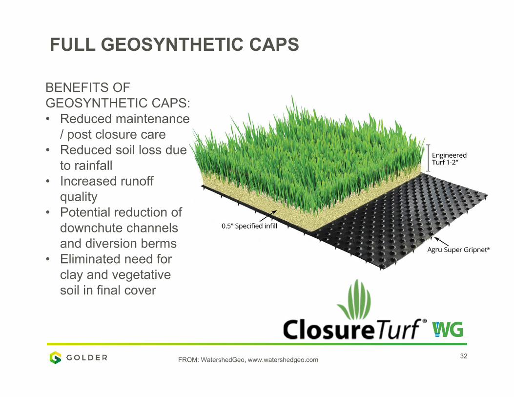
FULL GEOSYNTHETIC CAPS
BENEFITS OF GEOSYNTHETIC CAPS: • Reduced maintenance
/ post closure care• Reduced soil loss due
to rainfall • Increased runoff
quality • Potential reduction of
downchute channels and diversion berms
• Eliminated need for clay and vegetative soil in final cover
FROM: WatershedGeo, www.watershedgeo.com
___
33
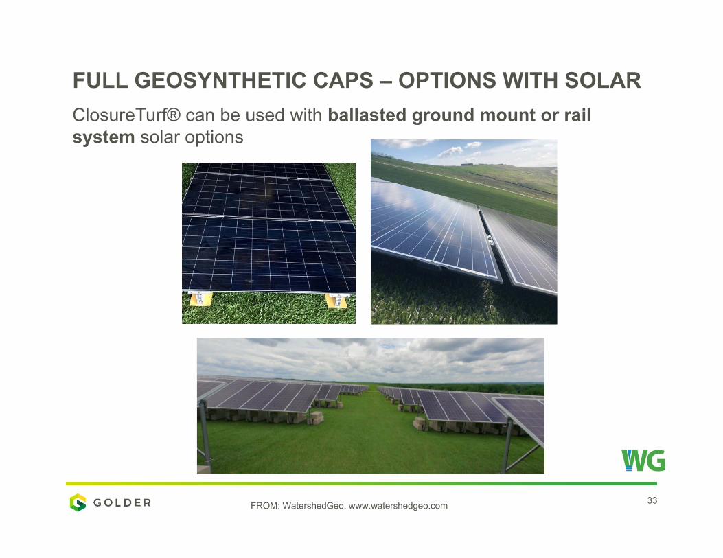
FULL GEOSYNTHETIC CAPS – OPTIONS WITH SOLAR
FROM: WatershedGeo, www.watershedgeo.com
ClosureTurf® can be used with ballasted ground mount or rail system solar options

___
34
RAIL SYSTEM
FROM: WatershedGeo, www.watershedgeo.com
=
Friction Strip Embedded Rail Attachment PowerCap™ RacklessPanels
+

___
35
RAIL SYSTEM
BENEFITS: • Faster and easier installation• Can be installed on slopes (max 2H:1V)• Increased Density = more Power per acre ~ 1MW: 2-3 Acres • Long term reliability, 30-year manufacturer warranty
FROM: WatershedGeo, www.watershedgeo.com
Friction Strip Installation Panel Installation
___
36
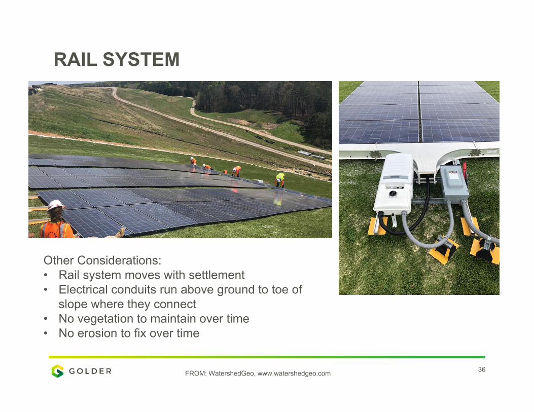
RAIL SYSTEM
FROM: WatershedGeo, www.watershedgeo.com
Other Considerations:• Rail system moves with settlement • Electrical conduits run above ground to toe of
slope where they connect • No vegetation to maintain over time • No erosion to fix over time

___
37
BALLASTED SYSTEMS
FROM: WatershedGeo, www.watershedgeo.com
THANK YOU. QUESTIONS?