Embed Size (px)
Citation preview

SOLAR INVERTER CHARGER
Product Manual
Product Type
HF4830S60-H | HF4850S80-H | HF4835U60-H
HF4850U80-H | MF4830S60-H | MF4850S80-H

Important Safety Instruction Please maintain the manual for reference in the future The manual comprises all safety, installation and operation instruction for HF/MF48-H Solar Energy Storage
and Inverting Control All-in-one Machine. Before installation and use, please carefully read all instructions and notices in the manual.
There is unsafe voltage inside the all-in-one machine. In order to avoid personal injury, the user shall not
dismantle the machine by himself. To repair the machine, it is required to contact the company's professional
maintenance personnel.
Do not place the all-in-one machine in the reach of children.
The all-in-one machine has the protection grade of IP20, which belongs to indoor application products. It is
strictly prohibited to use outdoors,because there is no warranty for outdoor use damage.
Do not install the all-in-one machine in a humid, oily, inflammable, explosive or dusty environment.
Municipal power input and AC output are high voltage, please do not touch the wire.
The all-in-one machine in working is very hot, so please do not touch the machine.
Please don’t open the terminal protection cover of the all-in-one machine in working.
It is recommended to install appropriate fuse or circuit breaker outside the all-in-one machine.
Make sure to disconnect the fuse or circuit breaker close to the photovoltaic array, mains supply and battery
terminals before installing and adjusting the wiring of the integrated machine.
Check whether all wires are connected firmly after installation to avoid danger of heat accumulation due to
virtual connection.
The all-in-one machine is the off grid type. It is required to confirm that the all-in-one machine is the unique
power supply input device for the load device. It is forbidden to use the machine in parallel with other input AC
power to avoid damage.
Solar Energy Storage Inverting & Control All-In-One Machine 2

Table of Contents 1. Basic Information ............................................................................................................................................ 4
1.1 Product overview and characteristics................................................................................................ 4
1.2 Basic system introduction.................................................................................................................... 5
1.3 Product characteristics........................................................................................................................... 7
1.4 Dimension drawing............................................................................................................................. 8
2. Installation Instruction.............................................................................................................................9
2.1 Installation notice.................................................................................................................................9
2.2 Wire specification and breaker type.............................................................................................10
2.3 Installation and Wiring......................................................................................................................11
3. Operating Mode........................................................................................................................................17
3.1 Charge mode........................................................................................................................................ 17
3.2 Output mode........................................................................................................................................17
4. Operation Instruction for LCD Screen................................................................................................20
4.1 Operation and display panel............................................................................................................20
4.2 Introduction to operation keys.......................................................................................................20
4.3 Introduction to indicator light......................................................................................................... 20
4.4 Introduction to LCD screen..............................................................................................................21
4.5 Setting parameter................................................................................................................................23
4.6 Battery type parameter................................................................................................ ......................30
5. Other Function............................................................................................................................................32
5.1 Dry node function............................................................................................................................... 32
5.2 RS485 communication function...................................................................................................... 32
5.3 USB communication function..........................................................................................................32
6. Protection ..................................................................................................................................................... 33
6.1 Protection function.............................................................................................................................33
6.2 Meaning of fault code.......................................................................................................................35
6.3 Some fault troubleshooting.............................................................................................................37
7. System Maintenance................................................................................................................................38
8. Technical Parameter.................................................................................................................................39
Solar Energy Storage Inverting & Control All-In-One Machine 3
1. Basic Information
1.1 Product overview and characteristics HF/MF48-H series is a new type of mixed solar energy storage inverting & control all-in-one
machine integrating solar energy storage & municipal power charge storage and AC sine wave output.
It adopts DSP control and advanced control algorithm to achieve characteristics of high response speed,
high reliability and high industrial standard. There are four charge modes namely only solar power,
mains power priority, solar power priority, mains power & solar power; and two optional output modes,
namely inverting and mains power to meet different application needs.
The solar charge module adopts the latest optimized MPPT tracking technology, which can
quickly track the maximum power point of the photovoltaic array in any environment to obtain the
maximum energy of the solar panel in real time with wide voltage range of MPPT.
AC-DC charge module adopts advanced control algorithm to realize full digital double closed-
loop control of voltage and current, with high control accuracy and small volume. Battery can be
charged and protected stably and reliably with wide AC voltage input range, full input/output
protection function.
DC-AC inverter module based on full digital intelligent design adopts advanced SPWM
technology, outputs pure sine wave, converts DC into AC. It is suitable for AC loads such as
household appliances, electric tools, industrial device, electronic audio-visual, etc. The product adopts
the segment LCD display design to display the operation data and state of the system in real time. The
comprehensive electronic protection function ensures that safety and stability of the whole system. Characteristics:
1. Adopt full digital voltage and current double closed-loop control and advanced SPWM
technology to output pure sine wave.
2. Two output modes, i.e. mains bypass and inverter output can achieve uninterrupted power
supply function.
3. Four optional charge modes: only solar energy, mains priority, solar energy priority and
mixed charge.
4. Advanced MPPT technology, with efficiency up to 99.9%.
5. Wide MPPT voltage range.
6. With function of activating lithium battery with solar energy and AC mains power, it
supports connection of lead-acid battery and lithium battery.
Solar Energy Storage Inverting & Control All-In-One Machine 4

7. LCD screen design and 3 LED indicator lights dynamically display system data and
operation states.
8.ON/OFF rocker switch can control AC output.
9.With power saving mode function, it can reduce no-load loss.
10.Intelligent adjustable speed fan is adopted for efficient heat dissipation and extended system
life.
11.Possessing multiple protection functions and 360° comprehensive protection.
12.Possessing complete short circuit protection, overvoltage and undervoltage protection,
overload protection, back filling protection, etc.
13.It has the function of mixed load: when the battery is not connected, photovoltaic and
commercial power can supply power to the load at the same time (if there is no battery, the commercial
power must be connected). When the battery is full, it can also enter the mixed load mode, which can
make full use of the photovoltaic energy.
1.2 Basic system introduction The figure below shows the system application scenario of this product. A complete system
includes the following parts:
1. Photovoltaic module: convert the light energy into direct current energy and then charge the
battery via the all-in-one machine, or directly invert the light energy into alternating current to supply
power to the load.
2. Mains or generator: connected at the AC input, it can supply power to the load and charge the
battery at the same time. If no mains power or generator is connected, the system can also operate
normally. At this time, the load power is supplied by the battery and photovoltaic modules.
3. Battery: the battery is to ensure the normal power consumption of the system load in
case of no sufficient solar energy or mains supply.
4. Household load: it can be connected to various household and office loads, including AC loads such
as refrigerators, lamps, televisions, fans, air conditioners, etc.
5. Inverting and control all-in-one machine: the energy conversion device of the whole
system.
The specific system wiring mode is determined by the actual application scenario.
Solar Energy Storage Inverting & Control All-In-One Machine 5

Solar Energy Storage Inverting & Control All-In-One Machine 6

1.3 Product characteristics
① Overload protector ⑨ Dry contact port
② ON/OFF rocker switch ⑩ Cooling fan
③ AC input port ⑪ Battery port
④ AC output port ⑫ Cooling fan
⑤ Grounding screw hold ⑬ PV port
⑥ RS485-2 communication
⑭ Touch the key lightly
port
⑦ USB communication port ⑮ Indicator light
⑧ RS485-1 communication
⑯ LCD screen
port
Solar Energy Storage Inverting & Control All-In-One Machine 7

1.4Dimension drawing
Solar Energy Storage Inverting & Control All-In-One Machine 8

2. Installation Instruction
2.1 Installation notice
Before installation, please carefully read the manual and get familiar with the installation step.
Take care while installing the battery. When installing the lead-acid liquid battery, it is required to wear
goggles. Any body part contacting the battery acid must be washed with clear water in time.
Don ’ t place any metal object beside the battery to prevent short circuit of the battery.
Acid gas may be generated during battery charge. Therefore, it is required to ensure good ventilation
around the environment.
During cabinet installation, sufficient space shall be reserved around the all-in-one machine for heat
dissipation; do not install the all-in-one machine and lead-acid liquid battery in the same cabinet to
avoid the corrosion of the all-in-one machine by acid gas generated during battery operation.
Only the battery with type consistent with the all-in-one machine can be charged.
Loose connection points and corroded wires may cause great heat, thereby melting the insulation layer
of wires, burning the surrounding materials, or even causing fire. Therefore, all connectors must be
tightened, and the wires must be fixed with ties, so as to avoid the looseness of connectors caused by
wire shaking during mobile application.
Tie conductors are selected based on no greater than 5A/mm2 current density.
The machine installed outdoors shall be protected against direct sunlight and rain.
After the power switch is turned off, there is still high voltage inside the all-in-one machine. Please do
not open or touch the internal components, and carry out
relevant operation after the capacitor is fully discharged.
Please do not install the all-in-one machine in a humid, greasy, flammable, explosive or dusty or other
severe environments.
The polarity of the battery input end of this product shall not be reversed, otherwise the device may be
damaged easily or there may be some unpredictable dangers.
AC supply input and AC output are both high voltage, so please do not touch the wires.
Do not touch the fan in working to prevent injury.
It is required to confirm that the all-in-one machine is the unique power supply input device for the load
device. It is forbidden to use the machine in parallel with other input AC power to avoid damage.
Solar Energy Storage Inverting & Control All-In-One Machine 9

2.2 Wire specification and breaker type
For wiring and installation ways, it is required to observe national and local electrical specification requirements.
Recommended wiring specification and breaker type for photovoltaic array: the output current of the photovoltaic
array is affected by the form, connection way and illumination angle of photovoltaic array, therefore the minimum
wire diameter of the photovoltaic array is calculated based on the short circuit current of photovoltaic array. Please
refer to the short circuit current value in the specification of photovoltaic array (the short circuit current keeps
unchanged for the photovoltaic arrays in series connection; the short circuit current of photovoltaic arrays in
parallel connection is the sum of short circuit current of all components connected in parallel); the short circuit
current of the array cannot exceed maximum input current of PV.
Please refer to the table below for PV input wire diameter and switch:
Recommende Maximum PV input Recommended types of air
Type d wire
current switch or breaker
diameter
HF/MF4830S60-H 6mm²/10AWG 18A 2P-25A
HF/MF4850S80-H 6mm²/10AWG 18A 2P-25A
HF4835U60-H 6mm²/10AWG 18A 2P-25A
HF4850U80-H 6mm²/10AWG 18A 2P-25A
Note: the voltage in parallel shall not exceed maximum PV input open-circuit voltage.
Please refer to the table below for recommended AC input wire diameter and switch:
Recommende Maximum bypass Recommended types of air
Type d wire
input current switch or breaker
diameter
HF/MF4830S60-H 10mm²/7AWG 40A 2P-40A
HF/MF4850S80-H 10mm²/7AWG 40A 2P-40A
HF4835U60-H 10mm²/7AWG 40A 2P-40A
HF4850U80-H 10mm²/7AWG 63A 2P-63A
Note: there is already a corresponding breaker at input connection point of mains supply.
Therefore, no breaker may be equipped.
Solar Energy Storage Inverting & Control All-In-One Machine 10

Recommended input wire diameter and switch type for battery
Recommended
Rated battery Maximum Recommended types
Type discharge
wire diameter charge current of air switch or breaker
current
HF/MF4830S60-H 20mm²/4AWG 85A 60A 2P—120A
HF/MF4850S80-H 30mm²/2AWG 125A 80A 2P—200A
HF4835U60-H 25mm²/2AWG 100A 60A 2P—160A
HF4850U80-H 30mm²/2AWG 125A 80A 2P—200A
Recommended wire specification and breaker type for AC output
Rated Maximum
Recommended inverter AC Recommended types
Type bypass output
wire diameter output of air switch or breaker
current
current
HF/MF4830S60-H 10mm²/7AWG 13A 40A 2P-40A
HF/MF4850S80-H 10mm²/7AWG 22A 40A 2P-40A
HF4835U60-H 10mm²/7AWG 29A 40A 2P-40A
HF4850U80-H 10mm²/7AWG 42A 63A 2P-63A
Note: the wire diameter is only for reference. In case of long distance between photovoltaic array and all-in-one
machine or between all-in-one machine and battery, use thicker wire to reduce voltage drop and improve system
performance.
Note: above wire diameter and breaker are only for reference. Please select appropriate wire diameter and breaker
based on practical condition.
2.3 Installation and Wiring
Installation step: Step 1: confirm the installation position and heat dissipation space, confirm the installation position of all-in-one
machine, such as wall surface; to install the all-in-one machine, guarantee there is sufficient air flowing through the
cooling fins of all-in-one machine. At least reserve 200mm space at the left and right air outlets of the all-in-one
machine to guarantee heat loss through natural convection. Refer to the overall installation schematic above.
Warning: danger of explosion! Never install the all-in-one machine and lead-acid liquid battery into a same sealed space or in a sealed place with probable accumulation of battery gas.
Solar Energy Storage Inverting & Control All-In-One Machine 11

Step 2: Remove the terminal protection cover
Solar Energy Storage Inverting & Control All-In-One Machine 12

Step 3: wiring
AC input/output wiring method:
① Before AC input/output wiring, disconnect the external breaker at first and then confirm whether the
cable used is thick enough. Please refer to chapter “ 2.2 Wiring Specification and Breaker type”;
② Correctly connect AC input wire in accordance with cable sequence and terminal
position shown in the figure below. Please connect ground lead at first, and then live wire and mull wire;
: ground wire L: live wire N: null wire
③ Correctly connect AC output wire in accordance with cable sequence and terminal position shown in
the figure below. Please connect the ground wire at first, and then live wire and null wire. The ground wire is
connected to the ground screw hold through O-shaped terminal.
Solar Energy Storage Inverting & Control All-In-One Machine 13
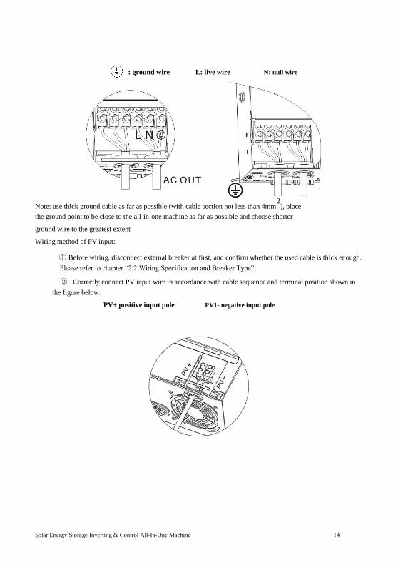
: ground wire L: live wire N: null wire
Note: use thick ground cable as far as possible (with cable section not less than 4mm2
), place the ground point to be close to the all-in-one machine as far as possible and choose shorter ground wire to the greatest extent Wiring method of PV input:
① Before wiring, disconnect external breaker at first, and confirm whether the used cable is thick enough.
Please refer to chapter “2.2 Wiring Specification and Breaker Type”;
② Correctly connect PV input wire in accordance with cable sequence and terminal position shown in
the figure below.
PV+ positive input pole PV1- negative input pole
Solar Energy Storage Inverting & Control All-In-One Machine 14

BAT wiring method: ①Before wiring, disconnect external breaker at first, and then confirm whether the used cable is thick
enough. Please refer to chapter “ 2.2 Wiring Specification and Breaker Type ” . BAT wire shall be
connected with the machine via O-shaped terminal. It is recommended to use the O-shaped terminal with
5mm inside diameter. The O-shaped terminal must compress BAT wire firmly to prevent excessive
heating caused by great contact resistance;
② Correctly connect BAT wire in accordance with cable sequence and terminal position shown in the
figure below.
BAT+: positive battery pole BAT-: negative battery pole
Warning notice: ① Input from mains supply, AC output and photovoltaic array may generate high voltage. Before wiring, make
sure to break the breaker or fuse;
② During wiring process, make sure to pay attention to the safety; during the wiring process, please don’t close the
breaker or fuse. At the same time, guarantee that “+” and “-” poles of different parts are correctly connected with
wires; a breaker must be installed at the battery end and selected based on chapter “2.2 Wiring Specification and
Breaker Type”. Before wiring, make sure to break the breaker to prevent strong electric spark generated during
wiring. At the same time, avoid battery short circuit during the wiring process; if the all-in-one machine is in the
area with frequent thunder, it is suggested to install an external arrester at PV input terminal. Step 4: inspect
whether the wires are correctly and firmly connected, especially whether the positive and negative input poles of the
battery are correct, whether the positive and negative input poles of PV are correct, whether AC input is
inaccurately connected to AC output terminal.
Step 5: install protective cap of terminal
Solar Energy Storage Inverting & Control All-In-One Machine 15

Step 6: Start all-in-one machine At first close the breaker at the battery end, and then press the rocker switch at the lower left side of the machine to
“ ON ” state, “ AC/INV ” indicator light flashes, indicating normal operation of inverter. Afterwards, close
breakers of photovoltaic array and mains supply. In the end, after AC output is normal, turn on AC load one by one
to avoid protection action generated by great instant impact owing to simultaneous turnon of loads. The all-in-one
machine operates normally in accordance with set mode. Note: if power is supplied to different AC loads, it is suggested to turn on the loads with great impact current, and
then turn on the load with little impact current after the load operates stably. Note: in case of abnormal operation of all-in-one machine or abnormal display of LCD or indicator light, refer to
Chapter 6 for troubleshooting.
Solar Energy Storage Inverting & Control All-In-One Machine 16

3.Operating Mode
3.1 Charge mode 1. Photovoltaic priority: in photovoltaic priority charge mode, mains charge is started only when photovoltaics is
out of work. Make full use of solar energy for power generation in the daytime and transfer to the mains supply
for charge to maintain electric quantity of the battery. It is suitable for areas with relatively stable power grid
and relatively expensive electricity price.
2. Mains supply priority: mains supply is to charge the battery preferentially and the photovoltaic charge can be
started only when the mains supply is valid.
3. Mixed charge: with mixed charge through photovoltaics and mains supply, photovoltaic MPPT charge is used
preferentially. In case of insufficient photovoltaic energy, the mains supply is used for supplement. In case of
sufficient photovoltaic energy, mains supply stops charge. Electricity can be charged fastest with the way,
which is suitable for the area with unstable power grid, so as to supply sufficient backup power supply at any
time.
Solar Energy Storage Inverting & Control All-In-One Machine 17

4.Only solar: only photovoltaic charge is used, no mains supply is started. This way can save the energy at most.
The electric energies of battery are all from solar energy. This way is suitable for areas with good light
condition.
3.2 Output mode
Photovoltaic priority mode: Photovoltaic and battery supply power to the load. With diversified charge
mode and optional output mode, when photovoltaic priority mode is selected, the green solar energy can be
used as far as possible so as to achieve energy conservation and emission reduction.
It switches to mains supply when the photovoltaics is invalid. With the mode, solar energy can be used
maximally and electric quantity can be maintained at the same time. Therefore, the mode is suitable for
areas with stable power grid.
Mains supply priority mode: it only switches to inverter for power supply when mains supply is invalid,
equivalent to a backup UPS. Therefore, the mode is applicable to area with unstable power grid.
Solar Energy Storage Inverting & Control All-In-One Machine 18

Inverter priority mode: it only switches to mains supply in case of undervoltage of battery. With the mode,
DC electric energy is used maximally. Therefore, it is applied to the area with stable power grid.
Mixed functions mode: When the battery is not available or the battery is fully charged, the load is provided by PV and commercial power, PV maximum output power output。
(Only used for MF)
Solar Energy Storage Inverting & Control All-In-One Machine 19

4. Operation Instruction for LCD Screen
4.1 Operation and display panel
Operation and display panel as shown below comprises one LCD screen, three indicator lights and four
operation keys.
4.2 Introduction to operation keys
Function Key Description
SET Enter/exit setting menu
UP Last option
DOWN Next option
ENT Confirm/enter option under setting menu
4.3 Introduction to indicator light
Indicator Color Description
light
AC/INV Yellow Constant on: mains supply output
Flashing: inverter output
CHARGE Green Flashing: battery in charge
Constant on: charge completed
FAULT Red Constant on: fault state
Solar Energy Storage Inverting & Control All-In-One Machine 20

4.4 Introduction to LCD screen
Icon Function Icon Function
Indicating that AC input end Indicating that inverter
has been connected to
circuit is in working.
power grid
Indicates that the AC input Indicating that the machine
is in mains supply bypass
mode in APL mode (wide
voltage range) work mode
Indicating that PV input end Indicating that AC output is
has been connected to solar
in overload state
battery panel
Indicating that machine has Indicating percentage of AC
been connected to battery, output load,
indicating 0%~24% indicating 0%~24% load
battery remaining percentage,
capacity indicating 25%~49% load
indicating 25%~49% percentage,
battery remaining capacity indicating 50%~74% load
indicating 50%~74% percentage,
battery remaining capacity indicating ≥75% load
Solar Energy Storage Inverting & Control All-In-One Machine 21

indicating 75%~100%
percentage
battery remaining capacity
Indicating that present Indicating that buzzer is not
battery type of the machine
enabled
is lithium battery
Indicating that current
battery type of machine is Indicating alarm of machine
lead-acid battery
Indicating that the battery is Indicating that the machine
in charge state. is in fault state.
Indicating that AC/PV Indicating that the machine
charge circuit is in working is in setting mode.
Middle parameter display of
screen,
1. In non-setting mode,
Indicating that AC output displaying alarm or fault
end has AC voltage output code; 2. In setting mode,
displaying code of
parameter item under
current setting.
Parameter display at left side of screen: input parameter
Indicating AC input
Indicating PV input
Indicating inverter circuit
The icon is not displayed
Displaying battery voltage, total charge current of battery, charge power of mains supply,
AC input voltage, AC input frequency, PV input voltage, temperature of internal radiator,
software version
Parameter display at right side of screen: output parameter
Indicating output voltage, output current, output active power, output apparent power, battery
discharge current, software version; under setting
Solar Energy Storage Inverting & Control All-In-One Machine 22

mode, displaying the setting parameter under the parameter item code set currently
Arrow display
① The arrow is not displayed ⑤ Indicating charge from
charge circuit to battery end
② Indicating power grid power
⑥ The arrow is not displayed
supply to load
Indicating power grid power
Indicating power supply
③ ⑦ from battery end to inverter
supply to charge circuit
circuit
④ Indicating PV power supply
⑧ Indicating power supply
to charge circuit from inverter circuit to load
Real-time data view method
In LCD main screen, press keys “UP” and “DOWN” to turn page and view different real-time data of the
machine. Middle
Right Parameter of
Page Left Parameter of Screen
Parameter of
Screen
Screen
1 Battery input voltage Output voltage
2 PV temperature PV output KW
3 PV input voltage PV output current
4 Input battery current Output battery current
5 Input battery KW Output battery KW
6 AC input frequency
Fault code AC output load
frequency
7 AC input voltage AC output load current
8 Input voltage Output load KVA
9 INV temperature INV output load KW
10 APP software version Bootloader software
version
11 Model Battery Voltage Rating Model Output Power
Rating
12 Model PV Voltage Rating Model PV Current Rating
4.5 Setting parameter Solar Energy Storage Inverting & Control All-In-One Machine 23

Key operation description: to enter setting menu and exit from setting menu, please press key “SET”. After
entering the setting menu, parameter number 【00】 shall flash. At this time, press keys “ UP ” and “ DOWN ” to
select the parameter item code to be set. Afterwards, press key “ ENT” to enter parameter editing state. At this moment, the parameter value can flash. The parameter values are
adjusted through keys “UP” and “DOWN”. In the end, press key “ENT” to complete parameter editing and return to
parameter selection state.
No. of Name of Setting Description
Parameter Parameter Option
00 Exit [00] ESC Exit from setting menu
At photovoltaic priority mode, when the
[01] SOL
photovoltaics is invalid or the battery values
are lower than the parameter 【04】 setting
value, it shall switch to AC power.
01 Work priority [01] UTI At AC priority mode, it switches to inverter
mode default only when the AC power is invalid.
At inverter priority mode, it switches to AC
[01] SBU
power only when battery is undervoltage or
lower than the setting value of parameter
【04】.
[02] 50.0 At bypass self-adaption, it automatically
adapts to AC frequency in case of AC power;
Output
02 without AC power, the output frequency can
frequency
be set via the menu. For 230V machine, it is
[02] 60.0
50Hz by default; for 120V machine, it is 60Hz
by default.
90~280V wide range input AC voltage range of
[03] APL 230V machine
AC input 90~140V AC input range of 120V machine
03 voltage
range
170~280V narrow range input AC voltage
[03] UPS
range of 230V machine
default
90~140V AC input range of 120V machine
Solar Energy Storage Inverting & Control All-In-One Machine 24

No. of Name of Setting Description
Parameter Parameter Option
When parameter【01】=SOL/SBU, the battery
04 Battery to [04] 46.0 voltage is lower than the set value, the output
bypass default is switched to mains or generator from battery.
The setting range is 44V~52V.
Bypass to
When parameter【01】=SOL/SBU, battery
05 [05] 56.0V voltage is higher than the set value, the output
battery default
is switched to battery from mains or generator
at 48V~60V setting range.
For photovoltaics priority charge, the AC
[06] CSO charge is started only when photovoltaics is
invalid.
[06] CUB
For AC priority charge, the photovoltaics
charge is started only when AC is invalid.
In case of mixed charge from photovoltaics
and AC power, priority is given to photovoltaic
charge. In case of insufficient photovoltaic
06 Charge mode energy, the AC charge is used for supplement.
[06] SNU In case of sufficient photovoltaic charge, stop
default charge from AC power. Note: photovoltaic
charge and AC charge can be performed at
the same time only when AC bypass is output
under load. When inverter works, only
photovoltaic charge can be started.
[06] OSO
Only photovoltaic charge, no AC charge is
started.
Maximum [07] 60A
07 charge Setting range 0~80A;
default
current
08 Battery type [08] USE For user-defined, all battery parameters can
be set.
Solar Energy Storage Inverting & Control All-In-One Machine 25

No. of Name of Setting Description
Parameter Parameter Option
Sealed lead-acid battery, constant voltage
[08] SLd charge voltage 57.6V, float charge voltage
55.2V.
For vented lead-acid battery, charge voltage
[08] FLd at constant voltage is 58.4V and float charge
voltage is 55.2V
[08] GEL
For gel lead-acid battery, charge voltage at
constant voltage is 56.8V and float charge
default
voltage is 55.2V.
Lithium iron phosphate battery L14/L15/L16
corresponds to lithium iron phosphate battery
[08] L14/L15 14 strings/15 strings/16 strings;16 string/15
/L16 string/14 string default constant
The voltage charging pressure is 56.8V, 53.2V,
49.6V, which are adjustable.
[08] N13/N14 Ternary lithium battery; which is adjustable.
Boost charge [09] 57.6V
The setting range of boost charge voltage is
09 48V~58.4V with 0.4V step. It is valid in case of
voltage default
a self-defined or a lithium battery.
Boost maximum charge time setting means
Boost charge [10] 120
setting of maximum charge time of voltage
10 maximum when the voltage reaches parameter 【09】
default
time from 5min~900min at 5-minute step. It is valid
in case of a self-defined or a lithium battery.
[11] 55.2V
48V~58.4V setting range of float voltage at
11 Float voltage 0.4V step is valid in case of a self-defined
default
battery.
So as to overdischarge voltage, when the
12 Overdischarg [12] 42V battery voltage is lower than the judgement
e voltage default point, after delaying for the parameter 【13】
setting time, turn off the inverter output.
Solar Energy Storage Inverting & Control All-In-One Machine 26

No. of Name of Setting Description
Parameter Parameter Option
40V~48V voltage setting range at 0.4V step is
valid in case of a self-defined battery and
lithium battery.
So as to overdischarge delay time, when the
battery voltage is lower than parameter
13 Overdischarg [13] 5S 【12】, the inverter output is turned off after
e delay time default delaying the time set with the parameter.
5S~50S setting range at 5S step is valid in
case of a self-defined and lithium battery.
So as to battery undervoltage alarm point,
Battery
when the battery voltage is lower than the
[14] 44V judgement point, an undervoltage alarm is
14 undervoltage
default given out and no turnoff is output. 40V~52V
alarm point
setting range at 0.4V step is valid in case of a
self-defined and lithium battery.
So as to battery discharge limiting voltage,
Battery when the battery voltage is lower than the
15 discharge [15] 40V judgement point, the output is turned off
limiting default immediately. 40V~52V setting range at 0.4V
voltage step is valid in case of a self-defined and
lithium battery.
[16] DIS No equalizing charge is permitted.
Equalizing
16 [16] ENA
When equalizing charge is enabled, only
charge
vented lead-acid battery and sealed lead-acid
default
are valid.
Equalizing
So as to equalizing charge voltage, 48V~58.4V
[17] 58.4V setting range at 0.4V step is valid in case of a
17 charge
default vented lead-acid battery and sealed lead-acid
voltage
battery.
So as to equalizing charge time, 5min~900min
18 Equalizing [18] 120 setting range at 5min step is valid in case of a
charge time default vented lead-acid battery and sealed lead-acid
battery.
Solar Energy Storage Inverting & Control All-In-One Machine 27

No. of Name of Setting Description
Parameter Parameter Option
For equalizing charge delay, 5min~900min
19 Equalizing [19] 120 setting range at 5min step is valid in case of a
charge delay default vented lead-acid battery and sealed lead-acid
battery.
Equalizing
For equalizing charge derating time, 0~30days
[20] 30 setting range at 1-day step is valid in case of a
20 charge
default vented lead-acid battery and sealed lead-acid
derating time
battery.
Equalizing [21] ENA Start equalizing charge immediately.
21 charge
[21] DIS Stop equalizing charge immediatel.
enabling default
[22] DIS No energy-saving mode
default
After enabling the energy-saving mode, in
22 Energy- case of empty or small load, the output is
saving mode [22] ENA turned off after output delaying of inverter for
a certain period of time. After the rocker
switch is pressed to “OFF” state and then to
“ON” state, the inverter restore the output.
When the automatic restart after overload is
[23] DIS
disabled, if the output is turned off upon
overload, the machine shall not restore
Automatic turnon.
23 restart after
When the automatic restart after overload is
overload [23] ENA
enabled, if the output is turned off upon
overload, output is restarted by the mains
default
after 3min delay. The machine shall not
restarted after 5 times of restarts.
When automatic restart after overtemperature
Automatic [24] DIS
is disabled, if the output machine is turned off
upon overtemperature, no output is turned
restart after
24
on.
overtemperat
ure [24] ENA When automatic restart after overtemperature
default is enabled, if the output is turned off upon
Solar Energy Storage Inverting & Control All-In-One Machine 28

No. of Name of Setting Description
Parameter Parameter Option
overtemperature, the output can be turned on
after the machine cools down.
[25] DIS Disabling alarm
25 Buzzer alarm
[25] ENA Enabling alarm
default
Mode [26] DIS
No alarm prompt in case of any change in
main input source
26 conversion
[26] ENA Alarm prompt is enabled if state of main input
reminding
default source is changed.
Inverter [27] DIS
No automatic switching to AC power in case
of inverter overload
27 overload to
[27] ENA Automatic switching to AC power in case of
bypass
default inverter overload
AC maximum
[28] 60A AC Out 230Vac
28 default Setting range 0~60A
charge
[28] 40A AC Out 120Vac
current
default Setting range 0~40A
[29] DIS Supply for industrial frequency transformer
29
default (disabled)
Split Phase
[29] ENA Supply for industrial frequency transformer
(enabled)
RS485 [30] 1 RS485 communication address setting range
30 address 1 ~ 254, (refer to Number [32] is valid when
default
setting set as SLA)
Battery [35] 50.4V
35 lowvoltage Setting range 44V~58.4V
default
recovery
Battery fully [37] 52V
After the battery is fully charged, it needs to be
37 charged lower than this set voltage before it can be
default
recovery point recharged
AC output
[38] 230Vac Settable劚 (200/208/220/240Vac劉
default
38 voltage
[38] 120Vac
setting
default Settable劚 (100/105/110Vac劉
Solar Energy Storage Inverting & Control All-In-One Machine 29
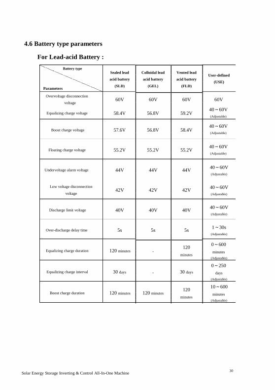
4.6 Battery type parameters
For Lead-acid Battery :
Battery type
Parameters
Overvoltage disconnection
voltage
Equalizing charge voltage
Boost charge voltage
Floating charge voltage
Undervoltage alarm voltage
Low voltage disconnection
voltage
Discharge limit voltage
Over-discharge delay time
Equalizing charge duration
Equalizing charge interval
Boost charge duration
Sealed lead Colloidal lead Vented lead
acid battery acid battery acid battery
(SLD) (GEL) (FLD)
60V 60V 60V
58.4V 56.8V 59.2V
57.6V 56.8V 58.4V
55.2V 55.2V 55.2V
44V 44V 44V
42V 42V 42V
40V 40V 40V
5s 5s 5s
120 minutes - 120
minutes
30 days - 30 days
120 minutes 120 minutes 120
minutes
User-defined
(USE)
60V
40~60V (Adjustable)
40~60V (Adjustable)
40~60V (Adjustable)
40~60V (Adjustable)
40~60V (Adjustable)
40~60V (Adjustable)
1~30s
(Adjustable)
0~600 minutes
(Adjustable) 0~250
days (Adjustable) 10~600
minutes (Adjustable)
Solar Energy Storage Inverting & Control All-In-One Machine 30

For Lithium Battery :
Battery type
Parameters
Overvoltage
disconnection
voltage
Equalizing
charge voltage
Boost charge voltage
Floating
charge voltage
Undervoltage alarm voltage
Low voltage
disconnection voltage
Discharge limit
voltage
Over- discharge delay time Equalizing
charge duration
Equalizing
charge interval
Boost charge
duration
Ternary Ternary Lithium Lithium Lithium
iron iron iron User-
lithium lithium
phosphat phosphat phosphat defined
battery battery
e battery e battery e battery (USE)
(N13) (N14)
(L16) (L15) (L14)
60V 60V 60V 60V 60V 60V
- - - - - 40~60V
(Adjustable)
53.2V 57.6V 56.8V 53.2V 49.2V 40~60V
(Adjustable) (Adjustable) (Adjustable) (Adjustable) (Adjustable) (Adjustable)
53.2V 57.6V 56.8V 53.2V 49.2V 40~60V
(Adjustable) (Adjustable) (Adjustable) (Adjustable) (Adjustable) (Adjustable)
43.6V 46.8V 49.6V 46.4V 43.2V 40~60V
(Adjustable) (Adjustable) (Adjustable) (Adjustable) (Adjustable) (Adjustable)
38.8V 42V 48.8V 45.6V 42V 40~60V
(Adjustable) (Adjustable) (Adjustable) (Adjustable) (Adjustable) (Adjustable)
36.4V 39.2V 46.4V 43.6V 40.8V 40~60V
(Adjustable)
30s 30s 30s 30s 30s 1~30s
(Adjustable) (Adjustable) (Adjustable) (Adjustable) (Adjustable) (Adjustable)
-
0~600
- - - - minutes
(Adjustable)
- 0~250
- - - - days
(Adjustable)
120 120 120 120 120 10~600
minutes minutes minutes minutes minutes minutes
(Adjustable) (Adjustable) (Adjustable) (Adjustable) (Adjustable) (Adjustable)
Solar Energy Storage Inverting & Control All-In-One Machine 31

5.Other Function
5.1 Dry node function
Working principle: this dry node can control the switch of diesel generator to charge
the battery. ① Under normal conditions, in this terminal, NC-N point is closed and NO-N
point is opened; ② when the battery voltage reaches the low-voltage disconnection voltage
point, the coil of the relay is energized and NO-N point is closed and NC-N point opened.
At this time, NO-N point can drive resistive loads 125VAC/1A, 230VAC/1A and
30VDC/1A.
5.2 RS485 communication function
There are two communication ports RS485-1 and RS485-2 and also two functions:
① RS485 communication with lithium battery BMS can be conducted directly
through this port RS485-2 (need to be customized);
② RS485-1 is connected to the selected RS485 to WiFi /GPRS communication
module independently developed by our company After the selected module is equipped, the
reverse control all-in-one machine of our company can be connected through mobile APP, and the operating
parameters and status of the reverse control all-in-one machine can be checked through the mobile APP.
③ Such as shown in the figure: pin 1 is 5V power supply; pin 2 is GND, pin 7 is RS485-A and pin 8 is
RS485-B.
5.3 USB communication function
This port is a USB communication port, which can be used for USB communication
with the selected upper computer software of our company (Need to apply for). To use
this port, the corresponding “USB to serial port chip CH340T driver” should be installed
in the computer.
Solar Energy Storage Inverting & Control All-In-One Machine 32

6.Protection
6.1 Protection function
No. Protection
Note
Function
1 Current limiting When the charge current of the configured PV array exceeds the
protection
rated current of PV, it will be charged at the rated current.
Anti-reverse At night, because the battery voltage is greater than that of the PV
charge
2
module, the battery shall be protected against discharge through
protection at
the PV module.
night
AC input over- When the AC voltage exceeds 280V (230V model) or 140V (120V
3 voltage model), the AC charge will be stopped and converted to inverter
protection for output.
AC input under- When the AC voltage is lower than 170V (230V model) or 90V
4 voltage (120V model), the AC charge will be stopped and converted to
protection inverter for output.
Battery
When the battery voltage reaches the overvoltage breaking
voltage point, charge from PV and AC power to the battery shall
5 overvoltage
be automatically stopped to prevent the battery from being
protection
damaged due to overcharge.
Battery low-
When the battery voltage reaches the low-voltage breaking
voltage point, the discharge to the battery will automatically
6 voltage
stopped to prevent the battery from damage owing to
protection
overdischarge.
In case of short-circuit fault at the load output end, the output of
Load output
AC voltage can be turned off immediately and then restored 1
minute later. After trying for 3 times, the output load end is still in
7 short circuit
short circuit state, it is required to eliminate the short circuit fault
protection
of the load at first, and then turn on the machine again to restore
normal output.
Radiator In case of excessive internal temperature, the all-in-one machine
8 overtemperatur shall stop charge and discharge; after the temperature returns to
e protection normal state, the all-in-one machine shall restore charge and
Solar Energy Storage Inverting & Control All-In-One Machine 33

discharge.
There is output within 3 minutes after overload protection. The
Overload
output is turned off in case of 5 times of continuous overload until
9 the machine is turned on again. Specific overload grade and
protection
duration are shown in the technical parameter table after the
manual.
AC reverse Prevent AC power inverted from battery inverting against reverse
10 flowing
flowing into bypass AC input.
protection
Bypass
11 overcurrent Built-in AC input overcurrent protection breaker.
protection
Solar Energy Storage Inverting & Control All-In-One Machine 34

6.2 Meaning of fault code
Fault Code Fault Name Affecting
Note
output or not
【01】 BatVoltLow Yes Battery undervoltage alarm
【02】 BatOverCurrSw Yes Average overcurrent software
protectionforbattery discharge
【03】 BatOpen Yes No connection alarm of battery
【04】 BatLowEod Yes Stop discharge alarm for battery
undervoltage
【05】 BatOverCurrHw Yes Battery overcurrent hardware
protection
【06】 BatOverVolt Yes Charge overvoltage protection
【07】 BusOverVoltHw Yes Bus overvoltage hardware
protection
【08】 BusOverVoltSw Yes Bus overvoltage software
protection
【09】 PV VoltHigh No PV overvoltage protection
【10】 PV OCSw No PV overcurrent software
protection
【11】 PV OCHw No PV overcurrent hardware
protection
【12】 bLineLoss No AC power failure
【13】 OverloadBypass Yes Bypass overload protection
【14】 OverloadInverter Yes Inverter overload protection
【15】 AcOverCurrHw Yes Inverter overcurrent hardware
protection
【16】 - - -
【17】 InvShort Yes Inverter short-circuit protection
【18】 - - -
【19】 OverTemperMppt No PV radiator overtemperature
protection
【20】 OverTemperInv Yes Overtemperature protection of
inverter radiator
【21】 FanFail Yes Fan fault
【22】 EEPROM Yes Memory fault
【23】 ModelNumErr Yes Inaccurate model setting
【26】 RlyShort Yes Inverted AC Output Backfills to
Solar Energy Storage Inverting & Control All-In-One Machine 35

Bypass AC Input
【29】 BusVoltLow Yes Bus undervoltage protection
Solar Energy Storage Inverting & Control All-In-One Machine 36

6.3 Some fault troubleshooting
Fault Solving Measures
Check whether the battery air switch or PV air switch is closed;
No display on screen whether the switch is in "on" state; press any key on the screen
to exit from the screen sleep mode.
Charge battery overvoltage Measure whether the battery voltage exceeds 60V, and
disconnect the photovoltaic array air switch and the AC air
protection
switch.
Battery undervoltage After the battery charge restores to be above low-voltage
protection disconnection recovery voltage.
Fan fault Check if the fan doesn't work or if it's blocked by something
else.
Radiator overtemperature When the device cools below the overtemperature recovery
temperature, it shall restore to normal charge and discharge
protection
control.
Bypass overload ① Decrease consumer; ② Restart all-in-one machine and the
protection, inverting
load output is restored.
overload protection
Inverting short-circuit ① Carefully check load connection condition, clear short-
circuit fault point; ② After power on again, the load output is
protection
restored.
PV overvoltage Check whether PV input voltage exceeds maximum
allowable input voltage with a multimeter.
No connection alarm of Check whether the battery is not disconnected or whether the
battery breaker at the battery side is not closed.
Solar Energy Storage Inverting & Control All-In-One Machine 37

7.System Maintenance
In order to maintain the optimum and permanent operation performance, it is suggested to check the
following items semiannually.
1. Confirm that the air flow around the all-in-one machine will not be blocked. In addition, remove any dirt or
debris from the radiator.
2. Check whether the insulation of all exposed wires is damaged due to sun exposure, friction with other objects
around, dry rot, insect or rat damage, etc. If necessary, it is required to repair or replace the wires.
3. Verify that the indication and display are consistent with the operation of the device. Please pay attention to any
fault or error display and take corrective measures if necessary.
4. Check all terminals for corrosion,insulation damage,high temperature or burning/discoloration sign, and tighten
the terminal screws.
5. Check for dirt, nesting insects and corrosion phenomenon and clean as required.
6. If the arrester has failed, replace the failed arrester in time to protect the all-in-one machine and other user
device against lightning damage.
Warning: Danger of electric shock! To perform above operations, make sure that all the power supplies of the all-
in-one machine have been broken and all the capacitor electricity has been discharged. Afterwards, corresponding
inspection or operation can be performed!
We are not responsible for any following damage:
① Damage caused by improper use or use in inappropriate place.
② Open-circuit voltage of photovoltaic module exceeds maximum allowable voltage.
③ The damage caused by the operation ambient temperature beyond the limited operation temperature range.
④ Personally take apart and maintain the all-in-one machine.
⑤ Damage caused by force majeure: damage caused by transportation and handling of the all-in-one machine. Solar Energy Storage Inverting & Control All-In-One Machine 38

8. Technical Parameter
Model HF4830S60-H MF4830S60-H HF4850S80-H MF4850S80-H HF4835U60-H HF4850U80-H
AC mode
Rated input voltage 220/230Vac 110/120Vac
Input voltage range
(170Vac~280Vac) ±2%
±2% (90Vac-140Vac)
(90Vac-280Vac) ±2%
Frequency 50Hz/ 60Hz (auto-sensing)
Frequency range 47±0.3Hz ~ 55±0.3Hz (50Hz);
57±0.3Hz ~ 65±0.3Hz (60Hz);
Overload/short- Breaker
circuit protection
Efficiency >95%
Conversion time
10ms (Typical value)
(Bypass and
inverting)
AC reverse flowing yes
protection
Maximum bypass 40A
63A
overload current
Inverting mode
Output voltage Pure sine wave
waveform
Rated output power 3000(2600/2700/3000)
5000(4350/4500/4800/5000) 3500(2900/ 5000(4100/
(VA)
3000/3200) 4300/4500)
Rated output power 3000(2600/2700/3000)
5000(4350/4500/4800/5000) 3500(2900/ 5000(4100/
(W)
3000/3200) 4300/4500)
Power factor 1
Rated output 230Vac(200/208/220/240Vac Settable) 120Vac (100/105/110Vac
voltage (Vac) Settable)
Output voltage ±5%
error
Output frequency 50Hz ± 0.3Hz
range (Hz) 60Hz ± 0.3Hz
Solar Energy Storage Inverting & Control All-In-One Machine 39

Efficiency >90%
(102%<load<110%) ±10%: reporting error
(102%<load<125%) ±10%: reporting error and turn off the output after 5 minutes; and turn off the output after 5 minutes;
(110%<load<125%) ±10%: reporting error
Overload protection (125%<load<150%) ±10%: reporting error and turn off the output after 10 seconds;
and turn off the output after 10 seconds;
Load>150% ±10%: reporting error and turn off the output after 5 seconds;
Load>125% ±10%: reporting error and turn
off the output after 5 seconds;
Peak power 6000VA 10000VA 7000VA 10000VA
Loaded motor 2HP
4HP 2HP
4HP
capacity
Output short-circuit Breaker
protection
Specification of 40A
63A
bypass breaker
Rated battery input 48V (minimum start voltage 44V)
voltage
Battery voltage 40.0Vdc~60Vdc ± 0.6Vdc (undervoltage alarm/turnoff
range voltage/overvoltage alarm/overvoltage restoration…settable LCD screen)
Power saving mode Load ≤50W
AC charge
Battery type Lead acid or lithium battery
Maximum charge 60A
40A
current
Charge current ± 5Adc
error
Charge voltage 40–60Vdc
range
Short-circuit Breaker and blown fuse
protection
Breaker 40A
63A
specification
Overcharge Turn off charge after 1min alarm
protection
Solar charge
Maximum PV open- 500Vdc 450Vdc 500Vdc
Solar Energy Storage Inverting & Control All-In-One Machine 40

circuit voltage
PV operation 120-500Vdc
120-450Vdc 120-500Vdc
voltage range
MPPT voltage 120-450Vdc
120-430Vdc 120-450Vdc
range
Battery voltage 40-60Vdc
range
Maximum output 4200W
5000W 4200W 5000W
power
Charge current 0-60A
0-80A 0-60A 0-80A
range of solar
energy (settable)
Charge short-circuit Blown fuse
protection
Wiring protection Inverse wiring protection
Authentication specification
Specification CE(IEC62109)、RoHs
authentication
EMC authentication EN61000
grade
Operation -15°C to 55°C
temperature range
Storage -25°C ~ 60°C
temperature range
Humidity range 5% to 95% (three-proof paint protection)
Noise ≤60dB
Thermal dissipation Forced cooling with adjustable air speed
Communication USB/RS485 (WiFi/GPRS)/dry node control
interface
Dimension (L*W*D) 426mm*322mm*126mm
Weight (kg) 10.9 11.6
Solar Energy Storage Inverting & Control All-In-One Machine 41