Embed Size (px)
Citation preview

S.Ü. Müh. Bilim ve Tekn. Derg., c.5, s.4, ss. 536-554, 2017
Selcuk Univ. J. Eng. Sci. Tech., v.5, n.4, ss. 536-554, 2017
ISSN: 2147-9364 (Electronic)
DOI: 10.15317/Scitech.2017.110
SOLAR ENERGY SUPPORTED HYDROGEN PRODUCTION: A THEORETICAL CASE STUDY
1Ali ATES, 2Sacit Zendehdel SHEKARDASHT, 3Eyüb CANLI
1,3Selcuk University, Department of Mechanical Engineering, Campus, Selcuklu, Konya, TURKEY
2Selcuk University, Graduate School of Natural Sciences, Selcuklu, Konya, TURKEY [email protected], [email protected], [email protected]
(Geliş/Received: 20.04.2017; Kabul/Accepted in Revised Form: 19.06.2017)
ABSTRACT: Hydrogen is an important energy vector and a strong candidate for energy storage. It will be a useful
tool for storing intermittent energy sources such as sun. The main objective of this work is to assess a system
harnessing solar energy in electrical form and store it as hydrogen by means of an electrolyzer for small scale
consumers away from the grid such as rural areas by computer simulation. Hydrogen then can be consumed in a
fuel cell in order to generate electricity. The electrical energy obtained from solar energy via photovoltaic panels was
used in order to charge a battery first and then hydrogen was acquired by using aforementioned energy in the
electrolysis of water. In the second stage, electricity is generated in a fuel cell by using the generated hydrogen. A
theoretical analysis was done via computer software by solving the constituted mathematical model. Data
containing monthly average insolation values of Konya City according to years were used in this model.
Electrolyzer temperature and pressure values and efficiencies of the photovoltaic panels were used as the input
parameters. General system efficiency and effectiveness, generated electricity and hydrogen amounts were obtained
as the output parameters. Among all, temperature was found to be the most effective parameter according to the
obtained results considering the generated hydrogen amount, system effectiveness and efficiency. A wide range of
electrical power between 400 W and 1800 W can be harnessed from the PV part of the system. Hydrogen production
in the other hand can be attained in the range of 120-130 g/month. Power curve of the fuel cell at the start up of the
system yields a 0.001 seconds reaction time. The proposed system can be utilized in rural parts of Konya and
climatically similar regions in the world.
Key Words: Electrolysis of water, Hydrogen fuel cell, Mathematical model, Photovoltaic.
Güneş Enerjisi Destekli Hidrojen Üretimi: Teorik Bir Vaka Çalışması
ÖZ: Hidrojen önemli bir enerji taşıyıcısıdır ve enerji depolanması için güçlü bir adaydır. Güneş gibi kesikli bir enerji
kaynağının depolanması için kullanışlı bir araç olacaktır. Bu çalışmanın ana amacı bir bilgisayar simulasyonu
vasıtası ile kırsal kesimler gibi elektrik şebekesinden uzaktaki küçük ölçekli tüketiciler için güneş enerjisinin
elektriksel formda elde edildiği ve saha sonra bir elektrolizer ile hidrojen şeklinde depolandığı bir sistemi
değerlendirmektir. Hidrojen daha sonra tekrar elektrik üretmek için bir yakıt hücresinde tüketilebilir. Önce güneş
enerjisinden fotovoltaik paneller aracılığı ile elde edilen enerji ile bir akü şarj edilmiş ve bu enerji suyun elektrolizi
işleminde kullanılmak suretiyle hidrojen elde edilmiştir. İkinci aşamada elde edilen hidrojen bir yakıt hücresinde
kullanılarak elektrik enerjisi elde edilmiştir. Oluşturulan matematiksel model, geliştirilen bilgisayar programı
vasıtası ile çözümlenerek teorik bir inceleme yapılmıştır. Bu modelde Konya iline ait güneş ışınımının yıllara göre
aylık ortalama değerlerine ait veriler kullanılmıştır. Giriş parametreleri olarak elektrolizör sıcaklığı, elektroliz basınç
değerleri ve fotovoltaik panellerin verimi kullanılmıştır. Genel sistem verim ve etkenliği, üretilen elektrik ve
hidrojen miktarları ise çıkış parametreleri olarak belirlenmiştir. Elde edilen sonuçlara göre, gerek üretilen hidrojen
miktarı yönünden, gerekse sistemin etkenliği ve verimi yönünden, giriş parametreleri arasında en etkili bileşenin
sıcaklık olduğu görülmüştür. Sistemin fotovoltaik kısmından 400 W ile 1800 W arasından geniş bir yelpazede
elektrik enerjisi elde edilebilmektedir. Diğer yandan aylık hidrojen üretimi 120-130 g/ay aralığındadır. Yakıt pilinin
güç eğrisi, 0.001 saniye cevap süresi ortaya koymuştur. Önerilen sistem Konya’da ve dünyada benzer iklim
özelliklerine sahip başka bölgelerde kullanılabilir.
Anahtar Kelimeler: Fotovoltaik, Hidrojen yakıt pili, Matematik model, Suyun elektrolizi
Solar Energy Supported Hydrogen Production 537
INTRODUCTION
Renewable energy is not only indispensable but also a new investment way for the small scale
investors. In the sectors such as agriculture, mining, industry and service, off grid renewable energy
systems have been emerging. For instance, photovoltaic (PV) systems are gaining more and more
importance in small scale applications. A comprehensive information compilation about PV panels can
be found in the report of Sayın and Koç (2011). With the existence of grid support, these systems work as
they are desired. However when the grid is not accessible, storing generated or harnessed energy is very
important due to two significant reasons: renewable energy sources are generally have an intermittent
characteristic and system capacities can’t response for instant energy demand increases.
Energy storage is a topic which has been investigated intensively for aforementioned systems where
grid support is out of the question. Batteries that include chemical reactions to store and release
electricity are the ones that come to mind in the first place. Storing heat by phase changing materials
such as salts, thermo-chemical heat storage materials such as salt hydrates, capacitors and hydrogen as
an energy vector can be listed as alternatives. Kleiner et al. (2017) mentioned about salt hydrates of
MgSO4, ZnSO4 and SrCl2 as promising thermo-chemical heat storage materials for later use of energy
generation. They investigated the thermal conductivity of these materials in order to provide
information for the optimization of this storage method. Another important point of this type of thermal
storage is emphasized by the authors that these materials store thermal energy relatively much more
time comparing to salt and/or water heat storage tanks. In the proposed system schematics of Amusat et
al. (2017), three different energy storage system were mentioned; i.e., Pumped Hydro Energy Storage
System, Advanced Adiabatic Compressed Air Energy Storage system and Molten Salt Tank system.
They investigated a sophisticated hybrid renewable energy generation system including these energy
storage systems from the aspect of reliability of the field application. Allison (2017) studied the multi-
objective control of a system containing solar energy electricity conversion system with the aid of an
electrical battery unit. The author stresses the importance of complex control systems and the need of
energy storage systems, in particular, batteries. Steam, water and oil are all used in a single integrated
combined power system as a heat storage sub system in the paper of Hu et al. (2017). Chong et al. (2016)
tried to attract attention to another important part of energy storing efforts for renewable energy
systems. The life span of these aforementioned energy storage systems were reported to be short by the
authors due to the irregular output of the renewable energy systems. They proposed hybrid energy
storage systems and decision matrixes. An interesting report was provided by Nojavan et al. (2017) about
utilization of electrolyzer, hydrogen and fuel cell as a renewable energy storage system. They evaluated
variables such as intermittent characteristics of renewable energy sources, market prices, demand
change and etc.
Hydrogen is an important material not only for energy systems but also for any industrial
applications as a raw material. Hydrogen should not be regarded as an energy source because it cannot
be found freely in the nature. Instead, hydrogen exists as part of other compounds. Generated energy
can be used to break these bonds and released hydrogen that has a high reaction potential can be stored
for later use. It can be used by combustion or by fuel cells. Another type of utilization is the bonding
with carbon atoms. By this way, methane and methanol can be synthesis and carbon dioxide also can be
captured in order to lower its impact on the environment. When hydrogen containing molecules are
synthesized, the densities increase and therefore required pumping work decreases. It leads to desired
flexibility for energy storage and transportation. The important point here is the strength of the bonds
between atoms of the synthesized molecules should be relatively weaker so that oxygen can react with
hydrogen when sufficient activation energy is presented. So hydrogen is generally regarded as an
energy vector or in other words energy cycle fluid. Therefore it is an important candidate for energy
transportation with relatively lower energy losses. Energy generated and desired to be transported in
North Africa is a good example for this task. In this sense, hydrogen is particularly important than local
energy storage systems such as water potential energy storage systems. Hydrogen bond to carbon can be

538 A. ATES, S. Z. SHEKARDASHT, E. CANLI
stored easily compared to pure hydrogen. This is due to the size of hydrogen atoms. Pure hydrogen can
escape almost any storage. The only reason of pure hydrogen storage systems is their structure that
slows down the movement of hydrogen atoms. Whether hydrogen is stored in its pure form or bond to
carbon or other matter, there are a lot of researches going on about the topic. Four main methods for
storing hydrogen can be mentioned here. The first one is the natural storing in caves and similar voids in
the ground. Since diffusion of hydrogen in the ground is relatively slow and there is no hazardous effect,
this is a favorable solution when short term storage is needed to damp excess or insufficient production.
There is a remarkable study of Bai et al. (2014) about the underground storage possibilities of hydrogen.
Authors summarized the opportunities and the works going on all around the world and they also give
local information. They exemplify some underground depots such as depleted reservoirs, aquifers, salt
caverns and excavated caverns. The second method is the pressurized depots or in other words
pressurizing. This solution is for smaller systems such as vehicles or small electrolysis units. Ali et al.
(2016) utilized Matlab Simulink software similar to the present work and considered the pressurized
hydrogen storage in their model. They also made an examination for the possible leakages and
concluded that their model is proper for relatively lower pressures. Fan et al. (2017) also considered a
pressurized hydrogen tank for their hybrid renewable energy system. They operated this tank for four
different modes. Their whole system exhibits similarities with the current work. There are known issues
about the compressed hydrogen storage, i.e. metal fatigue due to load cycles of the storage,
embrittlement of storage material due to the existence of hydrogen etc. So Guo et al. (2016) focused on
hydrogen gas cycling tests based on multi-stage storage and self pressurizing method. Also thin films
from multi-elemental sources for hydrogen storage applications are investigated and reported (Akyildiz
and Öztürk, 2013). The third one is the metal hydride hydrogen storages. Hydrogen is contained in the
crystal lattice structures in a stable manner in this solution. One of the mines used for metal hydrides is
the boron mineral and it is abundant in Turkey. However metal hydride hydrogen storage is still
expensive for certain applications. The topic is particularly attracting attention because of the quasi-
infinite possibilities in material research. A solid state hydrogen storage tank based on complex hydrides
and to fully integrate it with a High Temperature Proton Exchange Membrane fuel cell stack objective
was asserted by Baricco et al. (2017). A mixed lithium amide/magnesium hydride system was used as the
main storage material for the tank by the authors and it was equipped with a high temperature PEM fuel
cell. It is said that the storage system cooperates with the high temperatures and can release hydrogen
with relatively low temperatures, that is 170 oC. An extensive literature review was conducted by Yu et
al. (2017) and it is very useful for this content. They look for the recent advances and remaining
challenges for the hydrogen storage and consider the nano-materials in respect of the improvement.
Reader can find information about metal hydrides for the hydrogen storage as well as molecular
hydrogen storage and chemical hydrogen storage. Another comprehensive review was reported by
Kumar et al. (2017) about vanadium based hydrogen storage material. They suggested that vanadium is
a good alternative for the metal hydride hydrogen storage materials. Other superior properties can be
given as high hydrogen solubility and diffusivity in the material at nominal temperature and pressure
conditions. The last one is the chemical fuel synthesis though these produced fuels cause exhaust
emissions similar to their fossil fuel counterparts. An example is to convert hydrogen with carbon
dioxide to methanol and higher alcohols (Nieskens et al., 2011). A fixed bed reactor was used for the
conversion reaction and 3 times the H2 is mentioned to be needed for one unit of CO2 to reach significant
levels of conversion. 470-530 K and 5-19 MPa are reported to be the convenient intervals for the
conversion of hydrogen and carbon dioxide to methanol (Ostrovskii, 2002). The author focused on the
problems of heterogeneous catalyst situation and investigated the mechanisms for Cu-Zn containing
catalyst. As a conclusion, storing hydrogen in short term relatively cheap solutions and using it with a
fuel cell seems logical. Another chemical hydrogen storage system is proposed by Zhong et al. (2017).
Authors underline that the hydrolysis of NaBH4 offers significant advantages for hydrogen storage in
fuel cells, whereby suffers from the irreversibility. Hence they focused on a simple and low cost method
for NaBH4 regeneration from its hydrolysis byproduct. In the absence of an additional hydrogen source,

Solar Energy Supported Hydrogen Production 539
they utilized ball milling at ambient conditions and by his way they obtained the reaction of magnesium
silicate and dehydrate sodium metaborate.
Hydrogen can be used as a fuel in internal and external combustion engines. An important point
here is the hardening of the combustion chamber walls due to the presence of the hydrogen and
therefore occurring early fatigue in long term operation. Using a fuel cell for generating electricity for
hydrogen as a fuel seems to be the most efficient way to use hydrogen as an energy vector. The only
drawback of this option is the initial cost of the systems. Prices are decreasing lately and efficiencies of
the systems are going up. So fuel cell option becomes more favorable with passing years. Pure hydrogen
as well as methanol and methane can be used directly in fuel cells. Some informative literature examples
are as follows. Kivrak et al. (2013) investigated some elements for their direct ethanol fuel cell catalyst
usage. They also included structures at nano scale in their work. A novel fuel cell design is proposed by
Esquivel et al. (2017) which include single use papers in order to aid point of care diagnostic
applications. Their proposed design utilizes capillary action for the fluid movement and an exothermic
reaction which releases hydrogen as a byproduct. This design actually works as a hydrogen sensor and
the amount of hydrogen gives information about the liquid dropped on to the design. “More electric
aircraft” term in the recent years leaded Guida and Minutillo (2017) to study the potential of a PEM fuel
cell in aircrafts. The authors analyzed the feasibility, from the specific energy point of view, in using a
PEM fuel cell power system as APU unit in a more electrical aircraft with respect to a battery system
installation. Since fuel cells uses hydrogen as a fuel and they have relatively complex structures, feeding
hydrogen is an issue and Jia et al. (2017) focused on this subject. They stressed that existence of hydrogen
starvation for a fuel cell can detrimental effects on the unit. They investigated mitigation strategies for
the hydrogen starvation. Fuel cell combined heat and power plants attract attention of the scientists due
to the relatively higher temperatures experienced during electricity generation by fuel cells. The heat
released from the fuel cell can be used for the benefit of facilities and this increases total efficiency of the
system. Mamaghani et al. (2017) constituted a model for prediction of the HT-PEM unit and try to assess
adaptive long term optimization. Mohamed and Kamil (2016) investigated the preheating of hydrogen
by using a waste heat recovery system as an energy source and evaluate the power output improvement
for an open cathode PEM fuel cell system. They suggest a potential for hydrogen preheating by using
the waste heat from the fuel cell stack though only 3-6% of the waste heat can be used due to the small
amount of hydrogen flowing in the system.
Fuel cells and electrolyzer units operate on the same basic principle. Fuel cells can be thought
inversely working electrolyzer or vice versa. 20% of the world hydrogen generation comes from the
electrolysis method. The purest hydrogen can be acquired by electrolysis. Generating hydrogen by
electrolysis is not a good candidate for constituting energy vector of the future since its electricity cost is
higher than the energy obtained by using hydrogen in various energy conversion methods. There are
emission constraints for the hydrogen generation from coal or natural gas. Of course there are novel
techniques too; for instance Lashgari et al. (2017) proposed a highly efficient p-n junction nanocomposite
solar-energy-material for direct conversion of water molecules to hydrogen. They investigated the
presence of the carbon nanotubes for their solar-energy material and found that the photo catalyst acts
twice efficient. Another example is the report of Izgi et al. (2016) in which the effect of NaOH on
hydrogen production from NaBH4. Since Sodium hydroxide concentration in hydrogen production from
sodium boron hydride is immensely important to stabilize the reaction, and boron is an important
candidate for storing hydrogen, the study is important in this aspect. Electrolysis can be thought as an
alternative for storing energy when grid support is out of option and electricity is generated by
renewable and there is an excess of supply. Fallisch et al. (2017) proposes a PEM water electrolysis cell
design as a candidate for highly efficient solar hydrogen generator which is needed in countries having
abundant of renewable energy. Their work also contains content such as “Hydrogen Concentration”,
“on cell PEMs”, “multi-junction Solar Cells” and etc. On the other hand, higher rates of hydrogen
production can be achieved by application of microbial electrolysis cells as mentioned in the report of
Guo et al. (2017). They proposed a low resistance reactor design and reported a high hydrogen purity as

540 A. ATES, S. Z. SHEKARDASHT, E. CANLI
high as >98%. They also mentioned that their reactor can operate in a stable manner up to three weeks.
Anion exchange membrane electrolysis is mentioned by Vincent et al. (2017). They underlined the benefit
of using anion exchange membrane by using with non noble metals in the catalyst layer will lead to
lower initial costs. Their best electrolysis performance is reported as 500 mA cm-2 for 1.95 V at 60 oC with
1% K2CO3 electrolyte. Zhang et al. (2017) reported a novel electrode for solid oxide electrolysis cell and
found that H2O/H2 adsorption desorption or surface diffusion process is the main rate-limiting step for
steam electrolysis reaction.
There are also modeling studies similar to this work. A study considering a solar hydrogen system
was reported by Boudries (2013) in Algeria. The results indicate that concentrated solar power is more
convenient for the solar hydrogen systems. Ngoh et al. (2014) designed and simulated a high
temperature solar-hydrogen hybrid system in order to generate hydrogen. Exergy analysis and source
utilization are also reported.
This study, which is a compact summary and reorganized form of a MSc thesis of Zendehdel (2016),
comprises mathematical model of three systems and combines these models in to one single system
model. These systems are; firstly photovoltaic electricity production system; secondly hydrogen
production system and thirdly fuel cell system. The mathematical formulation of each system and the
main model for the whole system are provided. System parameters are explained and system behavior
as produced hydrogen and system efficiencies are illustrated. Both system model and the potential of
such systems for considered case site can be regarded as the valuable outcomes of this study.
The main objective of this research is to evaluate the potential of a combined system comprising a
PV system, an electrolyzer system and a fuel cell system for small scale energy consumers away from the
electricity grid such as rural areas in terms of continuity and avoiding intermittent characteristics of the
renewable energies.
The novel contribution to the specific literature can be stated as the local real world data used as
input for the present system to be simulated. By this way, domestic potential can be assessed. A detailed
literature survey alongside of the directions to the future work possibilities are also other favorable
contributions to be listed. The simulation presented here can be used in order to avoid costly trial and
error approaches or in other words reduce the possibilities.
MATERIAL AND METHOD
A schematic drawing of the general system is provided in Figure 1. As it can be seen from the figure,
the main energy source is the sun. The energy transported through the sun rays is harnessed via PV and
thermal solar collector panels in electricity and thermal heat forms. Of course some of the radiation is
reflected and some of the radiation passes through the panels. Absorbed energy is converted with
conversion efficiency. The heated water is fed to the electrolyzer with a manner to satisfy the thermal
energy need of the electrolyzer. For the generated electricity, things are relatively complicated. A power
regulator was utilized in order to regulate the electrical power. A portion of the electricity is sent to the
batteries through the charge control unit and rest is sent to the electrolyzer in the supervision of the
ECU. Again batteries supply the electrolyzer unit. Generated hydrogen first stored in a pressurized tank
and then sent to the Proton Exchange Membrane (PEM) fuel cell. The oxygen (O2) obtained via
electrolyses are released to the atmosphere. Oxygen is supplied to the PEM by using atmospheric air.
The whole system is operated by the ECU and the simulation is operated by the Matlab Simulink
software.
All data about the environment and the solar radiation of Konya City were gathered from
Meteorology Regional Directorate of Turkey and fed to the system mathematical model for the
simulation. Block diagrams were utilized in Matlab Simulink software in order to ease the simulation
process. Since numerous system components are exist, sub-systems were created and applied similarly.
In the following part, diagrams of the simulation process and related equations of the mathematical
model are provided respectively.

Solar Energy Supported Hydrogen Production 541
Figure 2 presents the main flow chart. Other diagrams for the sub systems refer to this main flow
chart. The input parameters of the simulation system are given in Table 1. Respectfully, Figure 3 exhibits
the block diagram of the energy harnessing part of the main system and related equations follow it.
Figure 1. Schematic drawing of the simulated system
Figure 2. Main flow chart of the simulation system
Table 1. Input parameters of the system
Solar Radiation of
Konya
Ambient Air
Temperature
Electrolyzer Stack
Temperature (K)
Electrolyzer Stack
Pressure (kPa)
Electrical
Conversion
Efficiency of the
PV System (%)
Monthly average values for 12 months
(January to December)
353 100 11.5
373 200 13.5
393 400 17
473

542 A. ATES, S. Z. SHEKARDASHT, E. CANLI
Figure 3. Energy harnessing sub system
The generated energy in the form of electricity in the PV can be expressed as following (Padin et al.,
2000):
qCAE PVPVPV (1)
Here PVE is the generated electricity amount in Watt, PV is electricity efficiency of the solar
panels, PVA is the area of the PV panels, q is the heat flux in radiation form of solar energy per unit
area. C is the correction factor. Generated thermal energy is as following (Padin et al., 2000);
qCAE SCSCSC
(2)
Again SCE is the thermal energy transferred to the water in Watt, SC is thermal efficiency of the
thermal solar collectors, SCA is the area of the thermal solar collectors. Total solar energy harnessed by
the collectors is:
SCSCPVPVtot AAqCE
(3)
The second sub system is the electrolyzer sub system. Figure 4 presents this sub system and
following are the related equations. Electricity is provided to the electrolyzer in two ways. The whole
electricity generated from the PV system is directed to the power regulator. A portion of this energy is
sent to the electrolyzer while the remaining part is sent to batteries in order to provide electricity to the
electrolyzer when the generated electricity from PV system is insufficient.
Figure 4. Electrolyzer sub system
Solar Energy Supported Hydrogen Production 543
The electrical energy electrolyzer uses for the unit mass of water can be expressed as following
(Rzayeva et al., 2001):
PTR
Uee ln105.6 5 (4)
Here U is the voltage needed for the electrolyses and it is between 48.1233.1 U in Volts. R is
the electrolyzer resistance in ohm (Ω), T stands for Temperature of the electrolyzer in Kelvin, P stands
for the pressure of the electrolyzer in kPa. Thermal energy entering to the electrolyzer via solar collector
for unit mass of water is (Padin et al., 2000);
tsTeth
(5)
s is the entropy difference for the electrolysis of the unit mass of water which is 116 J/kgK. t
stands for time in seconds. Total energy consumption of the electrolyzer is:
thetot eee
(6)
The electrical energy needed by the electrolyzer is calculated by:
e
th
SCelec e
e
EE
(7)
The hydrogen generated by the electrolyzer is:
th
SCOH
e
Em
92 (8)
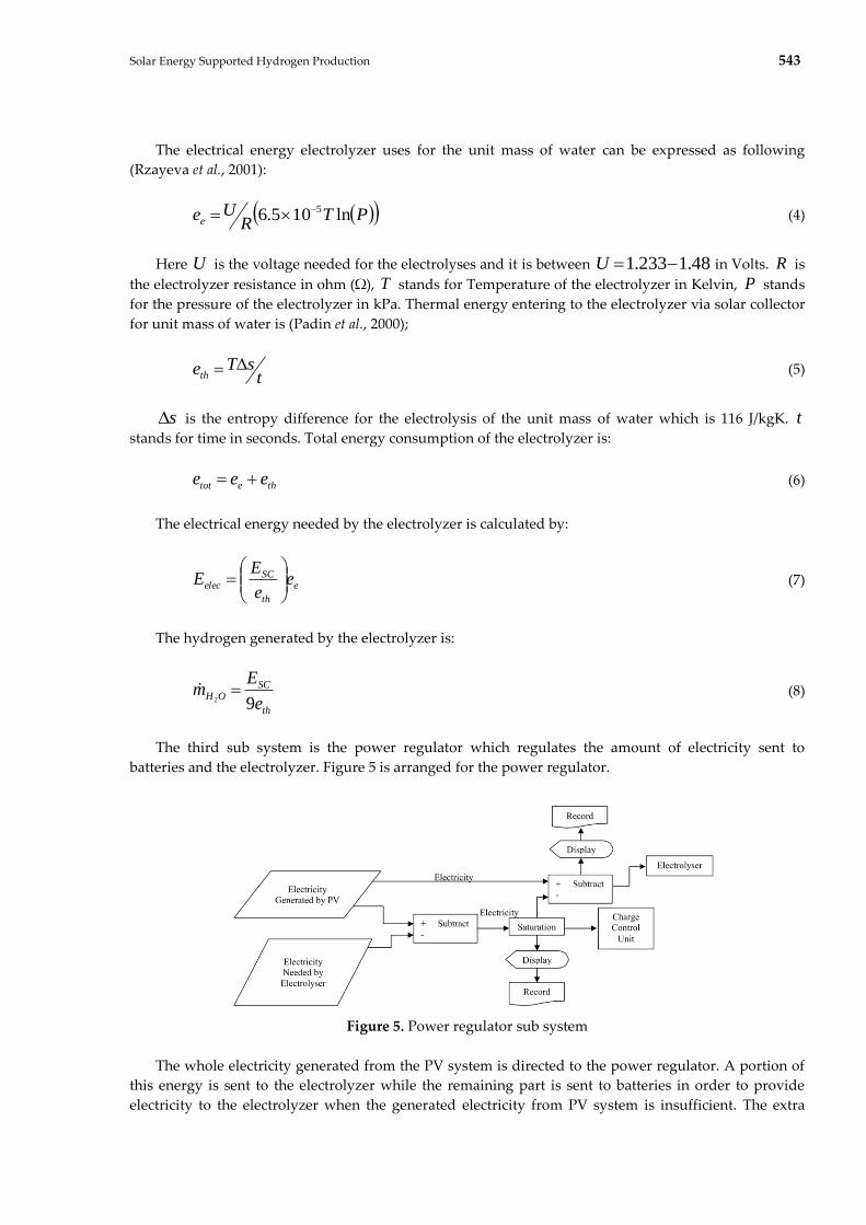
The third sub system is the power regulator which regulates the amount of electricity sent to
batteries and the electrolyzer. Figure 5 is arranged for the power regulator.
Figure 5. Power regulator sub system
The whole electricity generated from the PV system is directed to the power regulator. A portion of
this energy is sent to the electrolyzer while the remaining part is sent to batteries in order to provide
electricity to the electrolyzer when the generated electricity from PV system is insufficient. The extra
544 A. ATES, S. Z. SHEKARDASHT, E. CANLI
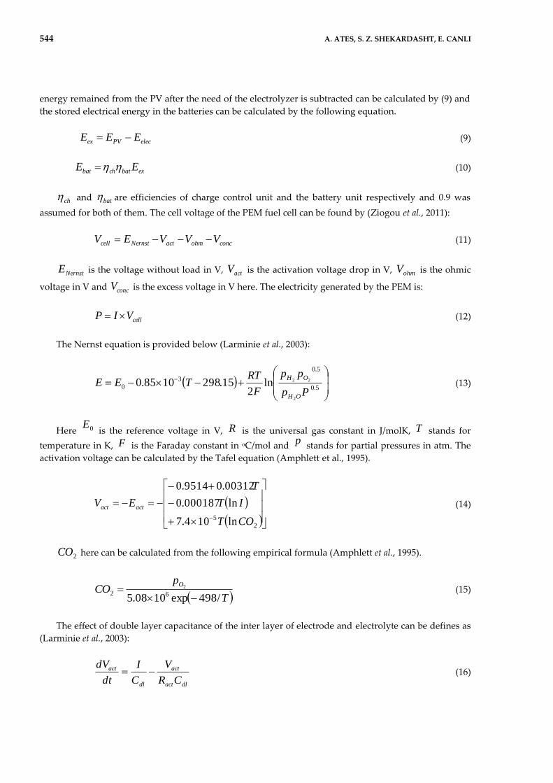
energy remained from the PV after the need of the electrolyzer is subtracted can be calculated by (9) and
the stored electrical energy in the batteries can be calculated by the following equation.
elecPVex EEE
(9)
exbatchbat EE (10)
ch and bat are efficiencies of charge control unit and the battery unit respectively and 0.9 was
assumed for both of them. The cell voltage of the PEM fuel cell can be found by (Ziogou et al., 2011):
concohmactNernstcell VVVEV (11)
NernstE is the voltage without load in V, actV is the activation voltage drop in V, ohmV is the ohmic
voltage in V and concV is the excess voltage in V here. The electricity generated by the PEM is:
cellVIP (12)
The Nernst equation is provided below (Larminie et al., 2003):
5.0
5.0
3
0
2
22ln2
15.2981085.0Pp
pp
F
RTTEE
OH
OH (13)
Here 0E is the reference voltage in V, R is the universal gas constant in J/molK, T stands for
temperature in K, F is the Faraday constant in oC/mol and p stands for partial pressures in atm. The
activation voltage can be calculated by the Tafel equation (Amphlett et al., 1995).
2
5 ln104.7
ln000187.0
00312.09514.0
COT
IT
T
EV actact (14)
2CO here can be calculated from the following empirical formula (Amphlett et al., 1995).
T
pCO
O
/498exp1008.5 622
(15)
The effect of double layer capacitance of the inter layer of electrode and electrolyte can be defines as
(Larminie et al., 2003):
dlact
act
dl
act
CR
V
C
I
dt
dV (16)
Solar Energy Supported Hydrogen Production 545
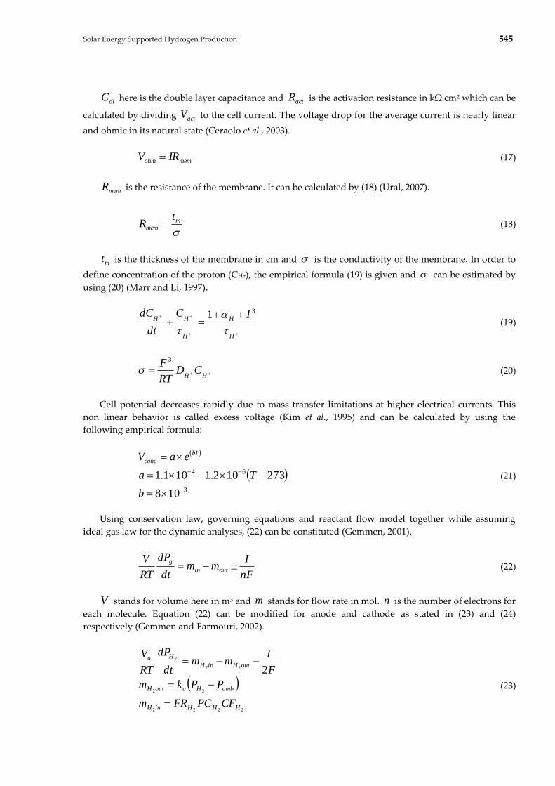
dlC here is the double layer capacitance and actR is the activation resistance in kΩ.cm2 which can be
calculated by dividing actV to the cell current. The voltage drop for the average current is nearly linear
and ohmic in its natural state (Ceraolo et al., 2003).
memohm IRV (17)
memR is the resistance of the membrane. It can be calculated by (18) (Ural, 2007).
m
mem
tR (18)
mt is the thickness of the membrane in cm and is the conductivity of the membrane. In order to
define concentration of the proton (CH+), the empirical formula (19) is given and can be estimated by
using (20) (Marr and Li, 1997).
H
H
H
HH IC
dt
dC
31 (19)
HH
CDRT
F 3
(20)
Cell potential decreases rapidly due to mass transfer limitations at higher electrical currents. This
non linear behavior is called excess voltage (Kim et al., 1995) and can be calculated by using the
following empirical formula:
3
64
108
273102.1101.1
b
Ta
eaV bI
conc
(21)
Using conservation law, governing equations and reactant flow model together while assuming
ideal gas law for the dynamic analyses, (22) can be constituted (Gemmen, 2001).
nF
Imm
dt
dP
RT
Voutin
g (22)
V stands for volume here in m3 and m stands for flow rate in mol. n is the number of electrons for
each molecule. Equation (22) can be modified for anode and cathode as stated in (23) and (24)
respectively (Gemmen and Farmouri, 2002).
2222
22
22
2
2
HHHinH
ambHaoutH
outHinH
Ha
CFPCFRm
PPkm
F
Imm
dt
dP
RT
V
(23)

546 A. ATES, S. Z. SHEKARDASHT, E. CANLI
2222
22
22
2
4
OOOinO
ambOcoutO
outOinO
Oc
CFPCFRm
PPkm
F
Imm
dt
d
RT
V
(24)
RESULT AND DISCUSSION
Konya is located in northern hemisphere of the world and it is above tropic of cancer. The latitudes
are 36041’ and 39016’ while longitudes are 31014’ and 34026’. Due to its geographical location, it receives
favorable amount of solar radiation in respect of energy. Figure 6 gives a good idea of the PV electricity
generation potential of the site and the region. Since real world data of the insolation periods and solar
radiation were used for the calculations, one can see that there is an electricity generation potential for
the whole year and this potential reaches to a maximum during summer months which are June, July
and August. Of course the conversion efficiency of the PV system plays a crucial role for the system
power output and determines the basic payback period of the system. This is particularly important for
the investors. The efficiencies in Figure 6 cover a practical range and these values are long achieved by
the manufacturers not only at cell level but also for the laminated panels.
For the first part of the results section, three PV efficiencies were taken into consideration. These
values are 11%, 13.5% and 17%. It can be seen from Figure 6 that the maximum power harnessed from
the PV setup can reach to 1800 W at peak solar insolation months while the minimum amount is about
300 W.
Four different electrolyzer temperatures were considered and these are 353 K, 373 K, 393 K and 473
K. This is particularly important since the design and material selection of such system are done
accordingly. Higher temperatures were not considered because this temperature interval is appropriate
for small scale systems and easy to handle for operation. Additionally three different electrolyzer
pressures were used and these values are 100 kPa, 200 kPa and 400 kPa. Simulations were run for these
aforementioned parameters and values. Data can be illustrated by three dimensional graphics however
reading those graphics is difficult so two dimensional graphics are preferred instead. These graphics are
presented for constant electrolyzer temperatures and constant electrolyzer pressures. Results indicate
that thermal energy input reduces electricity need of the electrolyzer for the same amount of generated
hydrogen and temperature of the electrolyzer increases the hydrogen generated.
Figure 6. Electrical energy generation for different PV efficiencies versus monthly average insolation
periods of KONYA
The energy required for the electrolysis is equal to the change of enthalpy (Padin et al., 2000):

Solar Energy Supported Hydrogen Production 547
3.68 QGH kcal/mol (25)
Here G is Gibbs free energy and Q is the change of thermal energy per mol of water. While
equations (4), (5), (7) and (8) in mind, equation (25) is very useful for the evaluation of the following
figures. Since total energy is constant for an amount of water to be spliced by electrolysis, the thermal
energy input reduces the electrical energy input for the same amount of generated hydrogen. In other
words, more hydrogen can be generated for the same amount of electricity generated from PV panels by
means of increasing thermal energy input. Because of there is storage opportunity for the electricity and
thermal energy obtained from the solar collectors should be used instantly, particularly for the systems
away from the grid support and there is no need for the excess thermal energy, this option seems logical.
A portion of electricity can be stored for the periods with no sun light. By this way, constant hydrogen
generation can be attained during day and night. Hence this scenario can be observed and examined by
figures 7, 8, 9 and 10. These figures should be evaluated together. A three dimensional figure can lower
the number of figures however this time reading data becomes difficult.
The effect of electrolyzer temperature and pressure can be observed in used electricity in the
electrolyzer and the difference in generated hydrogen considering the equation (4) and (5). Temperature
and pressure affect the unit energies by affecting Gibbs free energy and the entropy difference for the
thermal energy input. These effects are relatively small though, because the main determining
mechanism is the energy input to the system determining the share of the electricity and the thermal
energy in the electrolysis process.
a
b
c
d
Figure 7. Electrolyzer electricity consumption for fixed temperatures
The share of the electricity in the electrolysis process goes down with the increase in the thermal
energy input to the electrolyzer. PVs with integrated heat exchangers, i.e. PVTs, are of interest due to
this fact. Thermal heat collectors cool down the PVs in order to protect their efficiency levels while
generates heat energy for various aims, reducing electricity need of the electrolyzer for the generated
hydrogen amount this time. The least or minimum values can be seen in summer months because of the
548 A. ATES, S. Z. SHEKARDASHT, E. CANLI
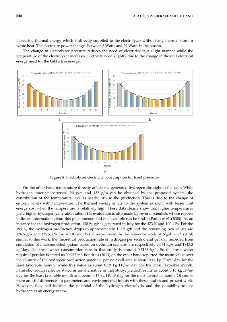
increasing thermal energy which is directly supplied to the electrolyzer without any thermal store or
waste heat. The electricity power changes between 8 Watts and 29 Watts in the season.
The change in electrolyzer pressure reduces the need of electricity in a slight manner while the
temperature of the electrolyzer increases electricity need slightly due to the change in the unit electrical
energy need for the Gibbs free energy.
a
b
c
Figure 8. Electrolyzer electricity consumption for fixed pressures
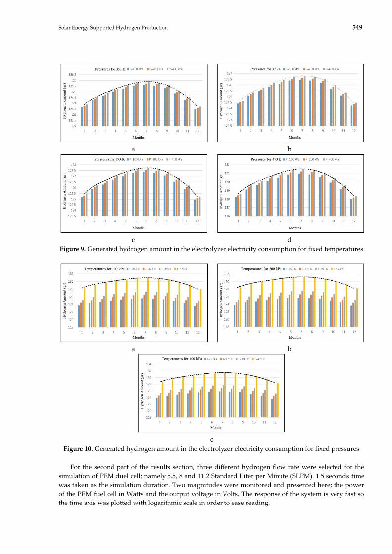
On the other hand temperature directly affects the generated hydrogen throughout the year. While
hydrogen amounts between 120 g/m and 132 g/m can be obtained by the proposed system, the
contribution of the temperature level is nearly 10% to the production. This is due to the change of
entropy levels with temperature. The thermal energy enters to the system is spent with lesser unit
energy cost when the temperature is relatively high. These data clearly show that higher temperatures
yield higher hydrogen generation rates. This evaluation is also made by several scientists whose reports
indicates information about this phenomenon and one example can be find in Padin et al. (2000). As an
instance for the hydrogen production, 130.94 g/h is generated in July for the 473 K and 100 kPa. For the
393 K, the hydrogen production drops to approximately 127.5 g/h and the remaining two values are
126.5 g/h and 125.5 g/h for 373 K and 353 K respectively. In the reference work of Ngoh et al. (2014)
similar to this work, the theoretical production rate of hydrogen per second and per day recorded from
simulation of interconnected system based on optimum scenario are respectively 0.064 kg/s and 1843.2
kg/day. The fresh water consumption rate in that study is around 0.7168 kg/s. So the fresh water
required per day is stated as 30.967 m3. Boudries (2013) on the other hand reported the mean value over
the country of the hydrogen production potential per unit cell area is about 0.14 kg H2/m2 day for the
least favorable month; while this value is about 0.19 kg H2/m2 day for the most favorable month.
Parabolic trough reflector stated as an alternative in that study, yielded results as about 0.10 kg H2/m2
day for the least favorable month and about 0.17 kg H2/m2 day for the most favorable month. Of course
there are still differences in parameters and environmental inputs with these studies and present work.
However, they still indicate the potential of the hydrogen electrolysis and the possibility to use
hydrogen as an energy vector.
Solar Energy Supported Hydrogen Production 549
a
b
c
d
Figure 9. Generated hydrogen amount in the electrolyzer electricity consumption for fixed temperatures
a
b
c
Figure 10. Generated hydrogen amount in the electrolyzer electricity consumption for fixed pressures
For the second part of the results section, three different hydrogen flow rate were selected for the
simulation of PEM duel cell; namely 5.5, 8 and 11.2 Standard Liter per Minute (SLPM). 1.5 seconds time
was taken as the simulation duration. Two magnitudes were monitored and presented here; the power
of the PEM fuel cell in Watts and the output voltage in Volts. The response of the system is very fast so
the time axis was plotted with logarithmic scale in order to ease reading.

550 A. ATES, S. Z. SHEKARDASHT, E. CANLI
a – 5.5 SLPM
b – 5.5 SLPM
c – 8 SLPM
d – 8 SLPM
e – 11.2 SLPM
f – 11.2 SLPM
Figure 11. Fuel cell power curve on the left column and voltage curve on the right column
The modeled PEM fuel cell nominal power output is 500 W. The DC voltage is 23 V and current is 22
A for this nominal output power. Although the maximum power of the PEM fuel cell is 1100 W, the
actual maximum is about 1000 W due to the internal resistances. DC voltage again can be taken as 23 V
for this case. The obtained current in the other hand would be 45 A. The hydrogen input for the 500 W
power is 5.5 SLPM. The hydrogen input to the PEM is 11.2 SLPM for 1000 W power output. 8 SLPM was
selected as an internal value and the power output for this flow rate is about 760 W. The electrical
current here is 33 A.
After a very short time, namely between 0.0001 and 0.001 seconds, the PEM fuel cell reaches to 500
W and 1.159 V for 5.5 SLPM flow rate of hydrogen. After this point, the system remains stable. For the 8
SLPM value, the power and voltage are 760 W and 1.159 V respectively for the same period. The
response time is same for 11.2 SLPM with the previous flow rates while power output is 1000 W.
CONCLUSION
An experimental energy generation system to be established in Konya is simulated in this study in
order to achieve the main objective that is proposing a system design that can be used for avoiding
intermittent characteristics of the solar energy by means of hydrogen storage. The results were acquired

Solar Energy Supported Hydrogen Production 551
by means of MATLAB-SIMULINKTM and an in-house MATLAB code for the simulation which consists
of electricity generation from PV panels, hydrogen generation by means of water electrolysis and using
this generated hydrogen in a PEM fuel cell. Necessary graphics are plotted by using the results from the
simulations.
Following conclusions can be drawn from the results.
There is an electricity generation potential for the whole year and this potential reaches
to a maximum during summer months which are June, July and August. The maximum
power harnessed from the PV setup can reach to 1800 W at peak solar insolation months
while the minimum amount is about 300 W.
The conversion efficiency of the PV system plays a crucial role for the system power
output and determines the basic payback period of the system.
Hydrogen production is increasing with increasing temperature in electrolysis unit.
Temperature and pressure affect the unit energies by affecting Gibbs free energy and the
entropy difference for the thermal energy input.
The share of the electricity in the electrolysis process goes down with the increase in the
thermal energy input to the electrolyzer.
As an instance for the hydrogen production, 130.94 g/h is generated in July for the 473 K
and 100 kPa. For the 393 K, the hydrogen production drops to approximately 127.5 g/h
and the remaining two values are 126.5 g/h and 125.5 g/h for 373 K and 353 K
respectively.
The chemical bonds between atoms in the molecules are weaker for the higher
temperatures and Gibbs free energy required for the electrolysis is lower for the higher
temperatures so the hydrogen generation at a high electrolyzer temperature is higher for
a constant voltage and current. The energy that the electrolyzer uses is not increasing
much with the increasing temperature or pressure.
After a very short time between 0.0001 and 0.001 seconds, the PEM fuel cell reaches to
500 W and 1.159 V for 5.5 SLPM, 760 W and 1.159 V for the 8 SLPM and 1000 W for 11.2
SLPM.
For the future work, following remarks can be given.
The designed system in the context of this study can be regarded as an ideal energy
generation system for the rural areas.
The stored hydrogen can be directly used as a clean and renewable fuel while it can be
used in a PEM fuel cell in order to generate electricity.
The electrolyzer is not a pressurized vessel in the study. Hence, the generated hydrogen
should be stored in a pressurized can by means of a compressor. If the electrolyzer
device can be defined as a pressurized volume, PEM fuel cell can be used directly
without utilizing an additional storage and compressor.
Since hydrogen storage by pressurizing is considered, various electrolyzer design
including pressurized ones can be considered to be utilized.
In the presence of a financial support, this simulation can be compared with the results
of an experimental setup.
Simulation can be enhanced by modeling the assumptions or integrating some more real
world data into the simulation.
As a general self evaluation of the present work, a considerable contribution to the specific literature
and the field is done. Presented data and the method can be used directly in order to give reference to an
idea or can be improved for a more detailed work. Real world data were used in order to provide inputs
for the simulated system and this is one of the novel contributions to the literature. The potential of the
region in terms of hydrogen generation and solar energy utilization can be assessed. Another important
contribution of the present work to the literature is the survey and evaluation of the similar works in an
extensively manner. By this way one can use this paper to assess the application with a wide

552 A. ATES, S. Z. SHEKARDASHT, E. CANLI
perspective. The simulation presented here can be used in order to avoid costly trial and error
approaches or in other words reduce the possibilities.
ACKNOWLEDGEMENT
The authors of this work would like to acknowledge the help and support of Selcuk University.
REFERENCES
Akyildiz, H., Öztürk, T., 2013, “Production of mg-Mased Amorphous/Nanostructured Thin Films from
Multi-Elemental Sources for Hydrogen Storage Applications”, J. Fac.Eng.Arch. Selcuk Univ.,
Vol. 28(1), pp. 1-10.
Ali, D., Gazey, R., Aklil, D., 2016, “Developing a Thermally Compensated Electrolyzer Model Coupled
with Pressurized Hydrogen Storage for Modeling the Energy Efficiency of Hydrogen Energy
Storage Systems and Identifying Their Operation Performance Issues”, Renewable and
Sustainable Energy Reviews, Vol. 66, pp. 27-37.
Allison, J., 2017, “Robust Multi-Objective Control of Hybrid Renewable Microgeneration Systems with
Energy Storage”, Applied Thermal Engineering, Vol. 114, pp. 1498-1506.
Amusat, O.O., Shearing, P.R., Fraga, E.S., 2017, “On the Design of Complex Energy Systems: Accounting
for Renewable Variability in Systems Sizing”, Computers and Chemical Engineering, Vol. 103, pp.
103-115.
Amphlett, J.C., Baumert, R.M., Mann, R.F., Peppley, B.A., Roberge, P.R., Harris, T.J., 1995, “Performance
Modeling of the Ballard-Mark-Iv Solid Polymer Electrolyte Fuel-Cell: 1. Mechanistic Model
Development”, Journal of the Electrochemical Society, Vol. 142(1), pp. 1-8.
Bai, M., Song, K., Sun, Y., He, M., Li, Y., Sun, J., 2014, “An Overview of Hydrogen Underground Storage
Technology and Prospects in China”, Journal of Petroleum Science and Engineering, Vol. 124, pp.
132-136.
Baricco, M., Bang, M., Fichtner, M., Hauback, B., Linder, M., Luetto, C., Moretto, P., Sgroi, M., 2017,
“SSH2S: Hydrogen Storage in Complex Hydrides for an Auxiliary Power Unit Based on High
Temperature Proton Exchange Membrane Fuel Cells”, Journal of Power Sources, Vol. 342, pp.
853-860.
Boudries, R., 2013, “Analysis of Solar Hydrogen Production in Algeria: Case of an Electrolyzer-
Concentrating Photovoltaic System”, International Journal of Hydrogen Energy, Vol. 38(26), pp.
11507-11518.
Ceraolo, M., Miulli, C., Pozio, A., 2003, “Modelling Static and Dynamic Behaviour of Proton Exchange
Membrane Fuel Cells on the Basis of Electro-Chemical Description”, Journal of Power Sources,
Vol. 113(1), pp. 131-144.
Chong, L.W., Wong, Y.W., Rajkumar, R.K., Rajkumar, R.K., Isa, D., 2016, “Hybrid Energy Storage
Systems and Control Strategies for Stand-Alone Renewable Energy Power Systems”, Renewable
and Sustainable Energy Reviews, Vol. 66, pp. 174-189.
Esquivel, J.P., Buser, J.R., Lim, C.W., Domínguez, C., Rojas, S., Yager, P., Sabate, N., 2017, “Single-use
Paper-Based Hydrogen Fuel Cells for Point-of-care Diagnostic Applications”, Journal of Power
Sources, Vol. 342, pp. 442-451.
Fallisch, A., Schellhase, L., Fresko, J., Zechmeister, M., Zedda, M., Ohlmann, J., Zielke, L., Paust, N.,
Smolinka, T., 2017, “Investigation on PEM Water Electrolysis Cell Design and Components for
a HyCon Solar Hydrogen Generator”, International Journal of Hydrogen Energy, Vol. 42(19), pp.
13544-13553.
Fan, X.C., Wang, W.Q., Shi, R.J., Cheng, Z.J., 2017, “Hybrid Pluripotent Coupling System with Wind and
Photovoltaic-Hydrogen Energy Storage and the Coal Chemical Industry in Hami, Xinjiang”,
Renewable and Sustainable Energy Reviews, Vol. 72, pp. 950-960.

Solar Energy Supported Hydrogen Production 553
Gemmen, R.S., 2001, ASME International Mechanical Engineering Congress and Expositions, New York.
Gemmen, R.S., Farmouri, P., 2002, “Power Elekteronics for Fuel Cells Workshop”, University of California,
Irvine, National Fuel Cell Research Center.
Guida, D., Minutillo, M., 2017, “Design Methodology for a PEM Fuel Cell Power System in a more
Electrical Aircraft”, Applied Energy, Vol. 192, pp. 446-456.
Guo, K., Prevoteau, A., Rabaey, K., 2017, “A Novel Tubular Microbial Electrolysis Cell for High Rate
Hydrogen Production”, Journal of Power Sources, Vol. 356, pp. 484-490.
Guo, J., Xing, L., Hua, Z., Gu, C., Zheng, J., 2016, “Optimization of Compressed Hydrogen Gas Cycling
Test System based on Multi-Stage Storage and Self-Pressurized Method”, International Journal
of Hydrogen Energy, Vol. 41(36), pp. 16306-16315.
Hu, K., Chen, L., Chen, Q., Wang, X.H., Qi. J., Xu, F., Min, Y., 2017, “Phase-change Heat Storage
Installation in Combined Heat and Power Plants for Integration of Renewable Energy Sources
into Power System”, Energy, Vol. 124, pp. 640-651.
Izgi, M.S., Odemis, O., Sahin, O., Saka, C., 2016, “Effect of NaOH in Hydrogen Production from NaNH4
by using Co-B-F and Co-B-P catalysts”, SUJEST, Vol. 4(1), pp. 55-64.
Jia, F., Guo, L., Liu, H., 2017, “Mitigation Strategies for Hydrogen Starvation under Dynamic Loading in
Proton Exchange Membrane Fuel Cells”, Energy Conversion and Management, Vol. 139, pp. 175-
181.
Kim, J., Lee, S.M., Srinivasan, S., Chamberlin, C.E., 1995, “Modeling of Proton Exchange Membrane Fuel
Cell Performance with an Empirical Equation”, Journal of the Electrochemical Society, Vol. 142 (8),
pp. 2670-2674.
Kivrak, H., Demir, N.C., Sahin, O., 2013, “Electrocatalytic Properties of Nanostructured Multimetallic Pt-
Sn-Cs/C and Pt-M/C (M=Ag, Ca, Cd, Cs, Cu, Fe, Ir, Mg, Pd, Sn, Zr) Direct Ethanol Fuel Cell
Catalysts”, Selcuk Univ. J. Eng. Sci. Tech., Vol. 1(2), pp. 19-28.
Kleiner, F., Posern, K., Osburg, A., 2017, “Thermal Conductivity of Selected Salt Hydrates for
Thermochemical Solar Heat Storage Applications Measured by the Light Flash Method”,
Applied Thermal Engineering, Vol. 113, pp. 1189-1193.
Kumar, S., Jain, A., Ichikawa, T., Kojima, Y., Dey, G.K., 2017, “Development of Vanadium Based
Hydrogen Storage Material: A review”, Renewable and Sustainable Energy Reviews, Vol. 72, pp.
791-800.
Larminie, J., Dicks, A., McDonald, M.S., 2003, Fuel Cell Systems Explained, Wiley, New York.
Lashgari, M., Elyas-Haghighi, P., Takeguchi, M., 2017, “A Highly Efficient pn Junction Nanocomposite
Solar-Energy-Material [nanophotovoltaic] for Direct Conversion of Water Molecules to
Hydrogen Solar Fuel”, Solar Energy Materials & Solar Cells, Vol. 165, pp. 9-16.
Mamaghani, A.H., Najafi, B., Casalegno, A., Rinaldi, F., 2017, “Predictive Modelling and Adaptive Long-
Term Performance Optimization of an HT-PEM Fuel Cell based Micro Combined Heat and
Power (CHP) Plant”, Applied Energy, Vol. 192, pp. 519-529.
Marr, C., Li, X., 1997, “An Engineering Model of Proton Exchange Membrane Fuel Cell Performance”,
ARI-An International Journal for Physical and Engineering Sciences, Vol. 50(4), pp. 190-200.
Mohamed, W.A.N.W., Kamil, M.H.M., 2016, “Hydrogen Preheating Through Waste Heat Recovery of an
Open-Cathode PEM Fuel Cell Leading to Power Output Improvement”, Energy Conversion and
Management, Vol. 124, pp. 543-555.
Ngoh, S.K., Ohandja, L.A., Kemajou, A., Monkam, L., 2014, “Design and Simulation of Hybrid Solar
High-Temperature Hydrogen Production System using both Solar Photovoltaic and Thermal
Energy”, Sustainable Energy Technologies and Assessments, Vol. 7, pp. 279-293.
Nieskens, D.L.S., Ferrari, D., Liu, Y., Kolonko R., 2011, “The Conversion of Carbon Dioxide and
Hydrogen into Methanol and Higher Alcohols”, Catalysis Communications, Vol. 14(1), pp. 111-
113.
Nojavan, S., Zare, K., Mohammadi-Ivatloo, B., 2017, “Application of Fuel Cell and Electrolyzer as
Hydrogen Energy Storage System in Energy Management of Electricity Energy Retailer in the

554 A. ATES, S. Z. SHEKARDASHT, E. CANLI
Presence of the Renewable Energy Sources and Plug-in Electric Vehicles”, Energy Conversion
and Management, Vol. 136, pp. 404-417.
Ostrovskii, V.E., 2002, “Mechanisms of Methanol Synthesis from Hydrogen and Carbon Oxides at Cu–
Zn-containing Catalysts in the Context of Some Fundamental Problems of Heterogeneous
Catalysis”, Catalysis Today, Vol. 77(3), pp. 141-160.
Padin, J., Veziroglu, T., Shahin, A., 2000, “Hybrid Solar High-Temperature Hydrogen Production
System”, International Journal of Hydrogen Energy, Vol. 25(4), pp. 295-317.
Rzayeva, M., Salamov, O., Kerimov, M., 2001, “Modeling to Get Hydrogen and Oxygen by Solar Water
Electrolysis”, International Journal of Hydrogen Energy, Vol. 26(3), pp. 195-201.
Sayin, S., Koç, I., 2011, “Güneş Enerjisinden Aktif Olarak Yararlanmada Kullanilan Fotovoltaik (PV)
Sistemler ve Yapılarda Kullanım Biçimleri”, J. Fac.Eng.Arch. Selcuk Univ., Vol. 26(3), pp. 89-106.
(in Turkish)
Shekardasht, S.J., 2016, An Investigation on Generation of Solar Powered (pv) and Applications in Hydrogen
Fule Cells, MSc Thesis, Selcuk University Institute of Natural and Applied Sciences, , Konya
TURKEY. (in Turkish)
Ural, Z., 2007, Yakıt Pilleri ve Bir PEM Yakıt Pili Sisteminin Dinamik Benzetimi, MSc Thesis, Dicle University,
Institute of Natural Sciences.
Vincent, I., Kruger, A., Bessarabov, D., 2017, “Development of Efficient Membrane Electrode Assembly
for Low Cost Hydrogen Production by Anion Exchange Membrane Electrolysis”, International
Journal of Hydrogen Energy, Article In Press, 1-10.
(http://dx.doi.org/10.1016/j.ijhydene.2017.03.069)
Yu, X., Tang, Z., Sun, D., Ouyang, L., Zhu, M., 2017, “Recent Advances and Remaining Challenges of
Nanostructured Materials for Hydrogen Storage Applications”, Progress in Materials Science,
Vol. 88, pp. 1-48.
Zhang, L., Zhu, X., Cao, Z., Wang, Z., Li, W., Zhu, L., Li, P., Huang, X., Lü, Z., 2017, “Pr and Ti co-doped
Strontium Ferrite as a Novel Hydrogen Electrode for Solid Oxide Electrolysis Cell”,
Electrochimica Acta, Vol. 232, pp. 542-549.
Zhong, H., Ouyang, L.Z., Ye, J.S., Liu, J.W., Wang, H., Yao, X.D., Zhu, M., 2017, “An One-step Approach
Towards Hydrogen Production and Storage Through Regeneration of NaBH4”, Energy Storage
Materials, Vol. 7, pp. 222-228.
Ziogou, C., Voutetakis, S., Papadopoulou, S., Georgiadis, M.C., 2011, “Modeling, Simulation and
Experimental Validation of a PEM Fuel Cell System”, Computers & Chemical Engineering, Vol.
35(9), pp. 1886-1900.