Embed Size (px)
Citation preview

AUTHOR:
Ted Spooner
Chair of the Australian standards committeeresponsible for PV systems
Co-convener of the International Electrical Commission(IEC) working group on PV systems: TC82-WG3.
September 2011
Solar ElectricSystems –Safety forFirefighters
Prepared for the International Energy Agency

Solar Electric Systems –
Safety for Firefighters
September 2011
BY Ted Spooner
Chair of the Australian standards committeeresponsible for PV systems
Co-convener of the International ElectricalCommission (IEC) working group on
PV systems: TC82-WG3.
Preface
Many Solar Electric (Photovoltaic or PV) Power systems have been and continue to be installedin Australia. Over recent years there has been a rapid expansion of the industry and this is expectedto continue into the future. These systems are typically installed on roofs or may be installed onground mounted racks. Although fires caused by the PV systems themselves are rare, it is importantfor firefighters to be aware of the safety issues that might be involved when fighting a fire on astructure that incorporates a Photovoltaic (PV) System.
The basic information provided here will help in identifying when a PV system is present, itsbasic operation, what hazards exist, what is safe and how to minimise risks. Much has been writtenlately on this topic. Some information, unfortunately, has been inaccurate, and it is hoped that thisdocument will assist in clearing up some misconceptions. Short courses on PV systems and safetyfor fire fighters can also be arranged through the Australian PV Association on request.
This document discusses Grid-connected Systems which are the most prolific systems inAustralia. It addresses the questions:
What components comprise a system?
What issues are important when you arrive at a fire location?o How can I identify if a PV system is present at an installation?
o How do I shut down a System?
o Once shut down, are there still hazards?
Issues related to water on a PV array
Safety issues when entering a fire compromised building.
Disclaimer
This brochure provides only general information. In the event of fire, site specific advice should be sought.Neither the APVA nor Ted Spooner will be liable for any loss or damage caused by use of the informationherein.

Contents
Preface..............................................................................................................................................2
Grid Connected Systems ..................................................................................................................4
Introduction .................................................................................................................................4
System Components & Connection Diagram...............................................................................5
What issues are important when you arrive at a fire location? ..................................................6
How can I identify if a PV system is present at an installation? ..............................................6
How do I shut down a PV System? ..........................................................................................7
Once shut down are there still hazards? .................................................................................8
Issues Relating to Water on PV arrays and structures.............................................................8
When Entering a Building ........................................................................................................8
Other Issues .............................................................................................................................8
SUMMARY....................................................................................................................................9
APPENDIX A: Identification of System Components .....................................................................10
Solar Panels or Modules.............................................................................................................10
Solar Thermal panels .............................................................................................................10
Photovoltaic (PV) modules: ...................................................................................................11
Inverters and Disconnects..........................................................................................................14
Grid Connected Systems
Introduction
Grid connected systems are at the present time the most predominant PV systems installed.They only exist where an installation is connected to the main electricity supply system (“The Grid”).Many of these systems have been installed on domestic roofs. An example of a domestic roofinstallation is shown in photo 1.
Photo 1. Example of Domestic roof PV System
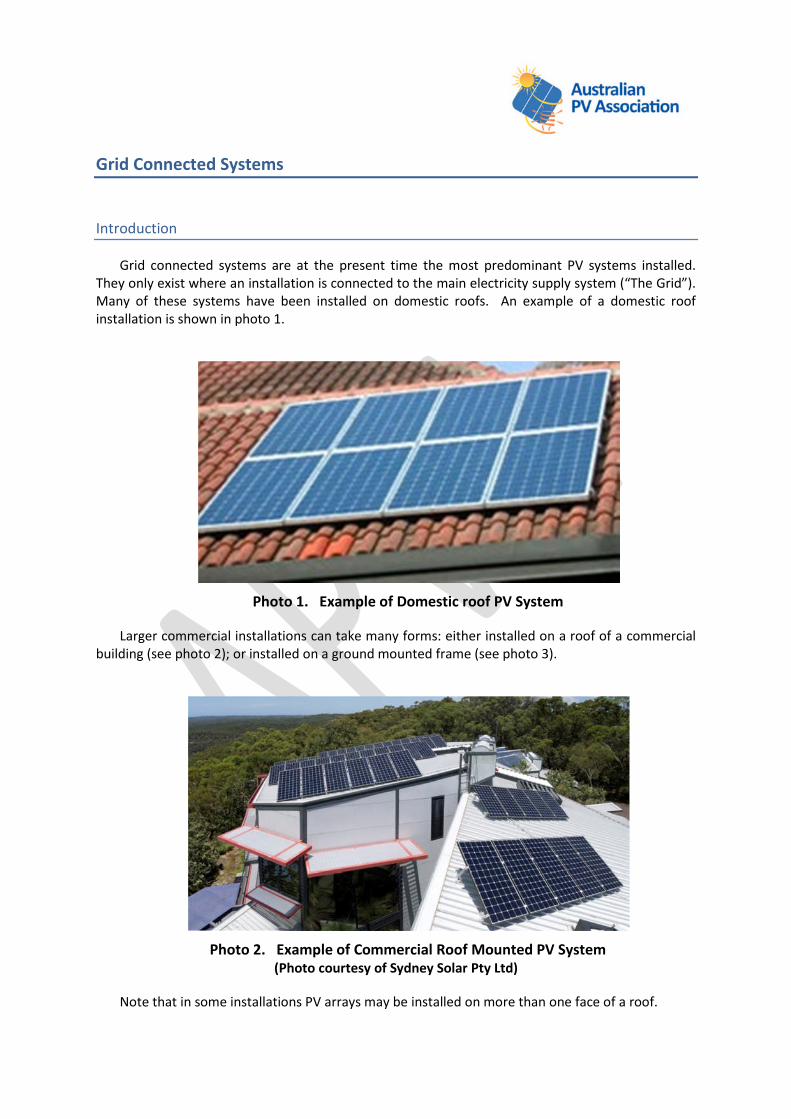
Larger commercial installations can take many forms: either installed on a roof of a commercialbuilding (see photo 2); or installed on a ground mounted frame (see photo 3).
Photo 2. Example of Commercial Roof Mounted PV System(Photo courtesy of Sydney Solar Pty Ltd)
Note that in some installations PV arrays may be installed on more than one face of a roof.

Photo 3. Example of Commercial Ground Mounted PV System
System Components & Connection Diagram
Grid connected PV systems have three primary components: modules, inverters, and the wiringconnections between the modules and inverter and between the inverter and the switchboard. Atypical connection diagram is shown in Figure 1. In some cases of grid connected systems, batteriesmay be present to provide an uninterruptible power supply (UPS) function but this is unusual andfrom a safety perspective is no different to any other installation containing a UPS.
The PV modules generate DC electricity while they are exposed to light. The amount ofelectricity generated is dependent on the size of the modules or complete system and the amount oflight falling on the modules.
The inverter converts the DC electricity into AC electricity that is compatible with the grid andinjects this electricity into the grid. Unless the PV output is separately metered, grid connected PVsystems will cause the electric meter to run backward on a sunny day when there is more powerbeing generated than the house is using. At nighttime, the meter just spins forward again as houseappliances are in use.
The inverters for grid connected systems cease operation and disconnect from the grid if thegrid supply is disconnected or fails for any reason. This includes someone switching off the mainelectricity supply to an installation.

SolarModules
Roof-TopDC Isolator
DC Isolator Inverter Switchboard
Figure 1. Typical domestic grid connected PV system diagram.
Note: Some older systems may not have roof-top DC isolators
What issues are important when you arrive at a fire location?
How can I identify if a PV system is present at an installation?
Determining the presence of a PV system is the first step in identifying potential risks. It isimportant for firefighters to be able to identify basic components of systems, such as the PVmodules and the inverter. See appendix A for assistance with identifying these components. Theexistence of these components in an installation will alert firefighters to the existence of a PVsystem. Sometimes, because of the location of PV modules on a roof, it is difficult or impossible tosee modules mounted on some parts of a roof. In all cases it is important if possible to go to theelectric meter panel or switchboard where in both cases there is required to be a sign/s displayedindicating the presence of a system. See an example of this signage in photo 4.
Note: This documentation covers only measures associated with a PV system. Other sources ofgeneration and devices, such as UPS systems, must be treated separately as per usual safetyprocedures for these devices.
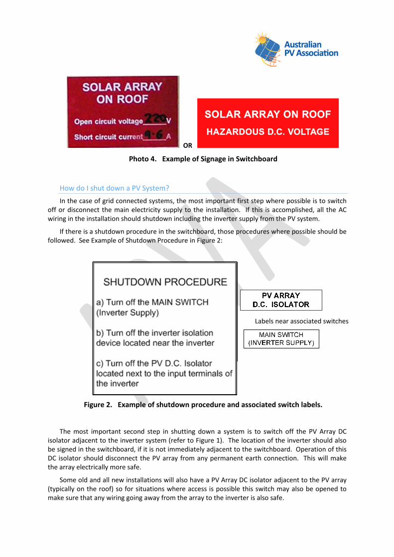
OR
Photo 4. Example of Signage in Switchboard
How do I shut down a PV System?
In the case of grid connected systems, the most important first step where possible is to switchoff or disconnect the main electricity supply to the installation. If this is accomplished, all the ACwiring in the installation should shutdown including the inverter supply from the PV system.
If there is a shutdown procedure in the switchboard, those procedures where possible should befollowed. See Example of Shutdown Procedure in Figure 2:
Figure 2. Example of shutdown procedure and associated switch labels.
The most important second step in shutting down a system is to switch off the PV Array DCisolator adjacent to the inverter system (refer to Figure 1). The location of the inverter should alsobe signed in the switchboard, if it is not immediately adjacent to the switchboard. Operation of thisDC isolator should disconnect the PV array from any permanent earth connection. This will makethe array electrically more safe.
Some old and all new installations will also have a PV Array DC isolator adjacent to the PV array(typically on the roof) so for situations where access is possible this switch may also be opened tomake sure that any wiring going away from the array to the inverter is also safe.
Labels near associated switches

Once shut down are there still hazards?
Once the a.c. mains to the installation is switched off, all the AC wiring should be safe. The PVsystem will not feed AC wiring in the installation after the mains have been switched off.
After switching off or disconnecting the AC to an installation, the DC wiring coming from the PVmodules to the inverter system may still have a dangerous DC voltage on it while there is any lightfalling on the array. This is certainly true in daylight conditions but may also be true under artificiallighting such as flood lights or with light associated with a fire. The electric current associated withPV arrays under artificial light is very significantly reduced compared to current under daylight, butstill it must be treated as potentially hazardous to humans.
Issues Relating to Water on PV arrays and structures
Remember that while there is light the PV array will be generating electricity. Voltages ondomestic systems may be up to 600V DC and on commercial installations up to 1000VDC.
It is important to operate fire hoses in a fog mode to break up the water path and ensure a nonconducting water stream.
Note: Further research on the issue of water streams and current flow from PV arrays will beavailable before the end of 2011 from testing being undertaken by Underwriters Limited in the USAbut until that time caution is important.
Note: Generally speaking the shock hazard from a PV array if the AC system is switched off andthe PV Array DC Isolator is switched off is likely to be much less than any shock hazard associatedwith normal AC power supplies. This is particularly true in low light conditions.
When Entering a Building
When entering a building that has been compromised by fire, firefighters should avoid contactwith any wiring hanging down from ceilings or roof structures under PV arrays or in the pathbetween the PV array and the inverter equipment. Again, if there is light on the PV array, some ofthese wires may be live unless all roof top isolator/s have been opened.
Other Issues
PV modules are not meant to be walked on - doing so could lead to a collapse.
If your department carries noncontact voltage detectors, remember that they detect onlythe presence of AC voltage, not DC voltage. There is no noncontact detector on the marketfor detecting DC voltage.
It is possible to make the PV array electrically safe using tarps to cover the array.Semitransparent tarps such as blue tarps are not suitable as they let too much light through.Silver, black or heavy canvas tarps are suitable and will reduce the available current from thearray to a level that is safe. It must be emphasized that the whole array has to be covered tomake this technique effective. On roofs with multiple sections of arrays, all sections of allarrays must be covered.

Photo 5. Tarping an array to make it electrically safe.
Finally, remember that in a nighttime fire in which the ceiling/roof space has been exposedto severe heat damage, the conduit and wires inside may have become compromised. It ispossible that when the sunlight contacts the array the next day, it could result in somearcing. It is a good idea to recheck a structure in the morning for arcing or rekindling fromarcing until a qualified solar contractor can respond to disconnect the array connections.
SUMMARY
1. On arrival, look for indications and signs associated with PV systems.
2. Turn off the AC supply. This will shutdown and disconnect the inverter.
- AC house wiring safe.
3. Shutting down the DC isolator near the inverter will separate the array from earth.
- Safer option.
4. Shutting down the rooftop isolator will make safe wiring coming down from the roof.
5. Use FOG spray when putting water on a fire.
6. When entering a building be aware of wires hanging down from the ceiling or roof structuresin areas under PV arrays.

APPENDIX A: Identification of System Components
Solar Panels or Modules
There are two main categories of solar panels (modules) used in residences:
Solar Thermal panels (photo A1 & A2), that are used for hot water systems and
Photovoltaic (PV) modules which generate electricity (photos A4 to A8).
This article deals only in detail with PV panels, also known as PV modules in the industry. It isimportant that fire-fighters are able to quickly distinguish the two different types.
Solar Thermal panels
Thermal panel systems may represent a physical load on the roof and may contain hot water.They sometimes have water tanks with electric or gas boost on the tank but the issues associatedwith these appliances are not covered in this document, other than to say that they need to beidentified and do not represent the same risks as PV systems because they do not generateelectricity.
Photo A1. Solar thermal panels used for hot water
Note: joined at top and bottom with water pipes
Photo A2. Solar thermal panels with storage tank.

Photo A3. House in Sydney Olympic Village Sydney with both solar thermal and solar PVelectric panels
Photovoltaic (PV) modules:
Most of the PV electric modules installed today are comprised of many silicon cells wiredtogether and enclosed in an aluminium frame with a glass cover. See photos A4 to A6. Crystallineand multicrystalline modules have individual cells that are easily seen under the glass in Photos A4-A6. Some modules are a double layer of glass with the cells sandwiched between to form asemitransparent module used often as atrium roofs or for shade elements in a building (photo A6).Amorphous cells are deposited as a thin uniform layer under the glass. See Photos A7-A8. Someamorphous modules come in the form of a thin plastic film that is bonded to metal deck roofing.See photo A8.
Photo A4. Mono-crystalline PV modules
Individual cells visible – uniform colour generally dark grey.
SolarThermalPanels
Solar PVmodules
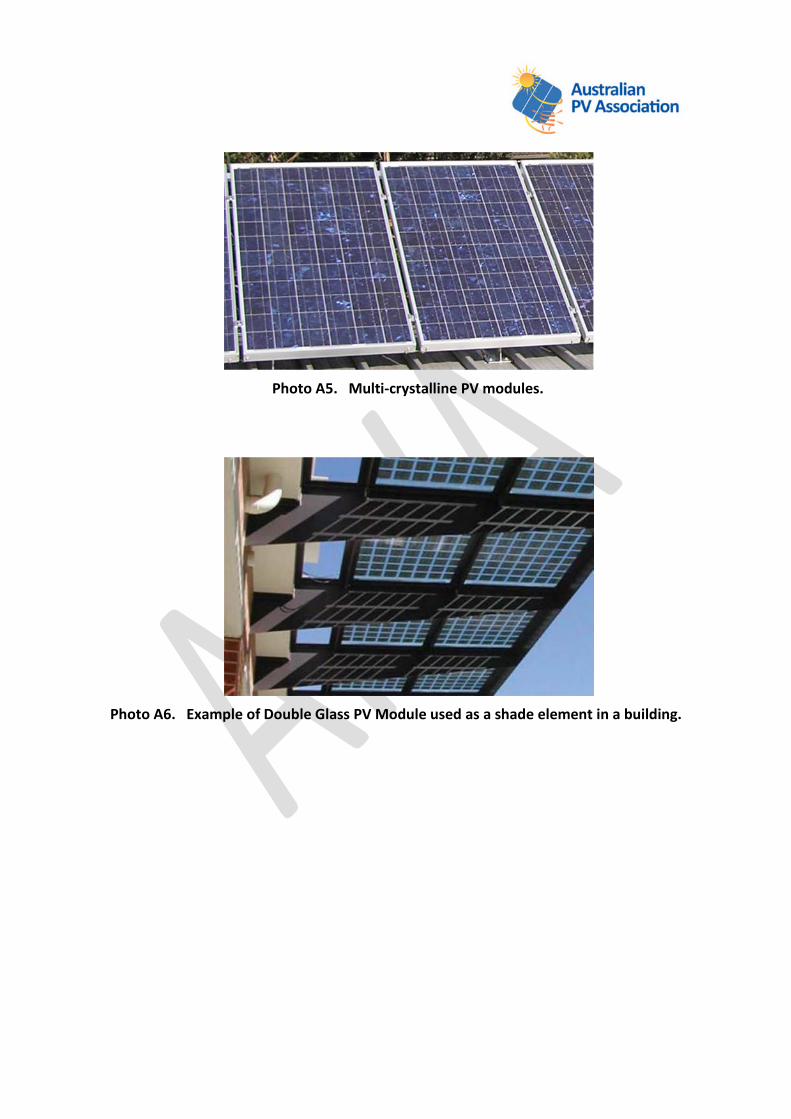
Photo A5. Multi-crystalline PV modules.
Photo A6. Example of Double Glass PV Module used as a shade element in a building.

Photo A7. Amorphous PV module
Note: The individual cells are not apparent – generally a uniform dark grey or bluish colour withfine lines on surface.
Photo A8. Amorphous modules bonded to metal roofing.
A group of modules mounted on a structure is called an array (photos 1-3). An array’s weightload on a roof is usually less than 25kg/sq meter. The modules generate electricity from sunlightand have no moving parts. When modules are electrically connected to each other in series, thevoltage increases. Most domestic residences will have from 1000 to 5000 watts (one to fivekilowatts) of power in optimal sunlight conditions, at between 120 and 600 volts DC. The currenttypically ranges between five and ten amps. Of course there are both smaller and larger systemsand Commercial PV systems can range up to 100s of kW through to megawatts. The larger systemstypically being on open racks in fields (photo 3).

Inverters and Disconnects
Since the modules produce DC power, they are wired to an inverter, which converts the voltageto alternating current (AC) and then feeds the electricity directly back into the main powerdistribution panel. Photo A9 shows, from left to right, the main electrical meter and circuit breakerswhich includes the AC disconnect, the inverter, and the DC disconnect underneath the inverter.
Photo A9. Example of Inverter installation adjacent to switchboard.
Note: The inverter may not always be mounted adjacent to the switchboard.
Since the inverter requires AC from the power company to do its job, shutting off the residence’smain circuit breakers also shuts down the inverter. This means that no AC power is being sent intothe house. Similarly, if there is a local power outage on a bright sunny day, the system cannot feedpower back into the power company grid because the inverter is shut down.
Switches for a.c and d.c disconnects should be close to the inverter to shut off the DC powerentering the inverter (the DC isolator/disconnect) and the AC power leaving it(AC isolator/disconnect). If the inverter is adjacent to the switchboard, as in the photo A9, the ACdisconnect will generally be on the switchboard.
Caution: The wires from the array to the inverter are live in the daytime hours, even when it isovercast. The DC disconnect does not shut off the power in the DC conduit coming from the array; itjust keeps it from entering the inverter. The DC wiring is still live between the array and the inverterDC disconnect. As you can see in photo A9, this inverter is mounted close to the main switchboard.Inverters may also be installed in other locations. Instructions as to the location of the invertershould be located in the switchboard.


![Heat Resistant Wire 600V Silicone, Rubber Insulated Glass Braided Cable Ishikawa Toku Electric Wire and Cable [MonotaRO Singapore] 600V LKGB](https://img.pdfslide.us/doc/110x75/55cf8572550346484b8e1a74/heat-resistant-wire-600v-silicone-rubber-insulated-glass-braided-cable-ishikawa.jpg)