Embed Size (px)
Citation preview

PModul-IEN094510 | 98-0020210 | Version 1.0 EN
Solar Data TechnologyPOWER MODULInstallation Guide


SMA Solar Technology AG Table of Contents
Installation Guide PModul-IEN094510 3
Table of Contents1 Information on this Guide . . . . . . . . . . . . . . . . . . . . . . . . . . 41.1 Area of Validity. . . . . . . . . . . . . . . . . . . . . . . . . . . . . . . . . . . . . . 41.2 Symbols Used . . . . . . . . . . . . . . . . . . . . . . . . . . . . . . . . . . . . . . . 42 Safety . . . . . . . . . . . . . . . . . . . . . . . . . . . . . . . . . . . . . . . . . . 52.1 Appropriate Usage. . . . . . . . . . . . . . . . . . . . . . . . . . . . . . . . . . . 52.2 Safety Instructions . . . . . . . . . . . . . . . . . . . . . . . . . . . . . . . . . . . . 63 Unpacking. . . . . . . . . . . . . . . . . . . . . . . . . . . . . . . . . . . . . . . 73.1 Scope of Delivery . . . . . . . . . . . . . . . . . . . . . . . . . . . . . . . . . . . . 73.2 Check for Transport Damage . . . . . . . . . . . . . . . . . . . . . . . . . . . 73.3 Identification . . . . . . . . . . . . . . . . . . . . . . . . . . . . . . . . . . . . . . . . 74 Electrical Connection . . . . . . . . . . . . . . . . . . . . . . . . . . . . . . 84.1 Notes . . . . . . . . . . . . . . . . . . . . . . . . . . . . . . . . . . . . . . . . . . . . . 84.2 Overview of the Connection Area . . . . . . . . . . . . . . . . . . . . . . . 84.3 Cabling Recommendations . . . . . . . . . . . . . . . . . . . . . . . . . . . . . 94.4 Installing the Power Modul into the inverter . . . . . . . . . . . . . . . . 95 Decommissioning . . . . . . . . . . . . . . . . . . . . . . . . . . . . . . . . 155.1 Removing the Power Modul from the inverter. . . . . . . . . . . . . . 156 Technical Data . . . . . . . . . . . . . . . . . . . . . . . . . . . . . . . . . . 167 Contact . . . . . . . . . . . . . . . . . . . . . . . . . . . . . . . . . . . . . . . . 17

Information on this Guide SMA Solar Technology AG
4 PModul-IEN094510 Installation Guide
1 Information on this Guide1.1 Area of ValidityThis guide describes the installation and connection of the Power Modul with hardware version Q3, and later.
1.2 Symbols UsedThe following types of safety instructions and general information appear in this document:
DANGER!
DANGER indicates a hazardous situation which, if not avoided, will result in death or serious injury.
WARNING!
WARNING indicates a hazardous situation which, if not avoided, could result in death or serious injury.
CAUTION!
CAUTION indicates a hazardous situation which, if not avoided, could result in minor or moderate injury.
NOTICE!
NOTICE indicates a situation that can result in property damage if not avoided.InformationInformation provides valuable tips for the optimal operation of your product.

SMA Solar Technology AG Safety
Installation Guide PModul-IEN094510 5
2 Safety2.1 Appropriate UsageThe Power Modul enables the power supply of the SMA Bluetooth Repeater via the internal voltage supply of SMA inverters of the type:
The Power Modul is exclusively suitable for use in the above mentioned SMA inverter types and for the power supply of the following consumers:
• SMA Bluetooth RepeaterYou receive the Power Modul as an upgrade kit. Please observe the respective manual of the inverter and the manual of the SMA Bluetooth Repeater. The Power Modul is only to be employed according to the information in this manual. Any other application may cause injury to persons or material damage.
Sunny Boy: Sunny Tripower:• SB 3000TL-20 • STP 10000TL-10• SB 4000TL-20 • STP 12000TL-10• SB 5000TL-20 • STP 15000TL-10
• STP 17000TL-10
No installation of the Power Modul possible in event of the use of RS485 communication.The Power Modul is to be installed on the slot for modules. The slot can only be fitted with 1 module. If the RS485 communication module (DM-485CB-10) is already installed, you must decide on one module. If you want to install the Power Modul, you must first remove the RS485 communication module.

Safety SMA Solar Technology AG
6 PModul-IEN094510 Installation Guide
2.2 Safety InstructionsDANGER!Risk of lethal electric shock when opening the inverter.
• All work on the inverter may be carried out by qualified personnel only.• Disconnect the inverter from both the DC and AC connections, as described in its
installation guide.
NOTICE!Electrostatic discharges can damage the module or the inverter.
• Ground yourself before touching the component by touching the PE or a non-coated part of the inverter enclosure.

SMA Solar Technology AG Unpacking
Installation Guide PModul-IEN094510 7
3 Unpacking3.1 Scope of Delivery
3.2 Check for Transport DamageCheck the module for visible external damage. Please contact your dealer if you find any damage.
3.3 IdentificationYou can identify the module by the type plate.
Position Quantity NameA 1 Power Modul (DM-POWER.BG1)B 1 M32 cable glandC 1 10 m pre-configured electricity cable
The electricity cable is suitable for both indoors and outdoors. The electricity cable is not suitable for a direct laying in the ground.
D 1 Installation guide
Position NameA Type Plate
Electrical Connection SMA Solar Technology AG
8 PModul-IEN094510 Installation Guide
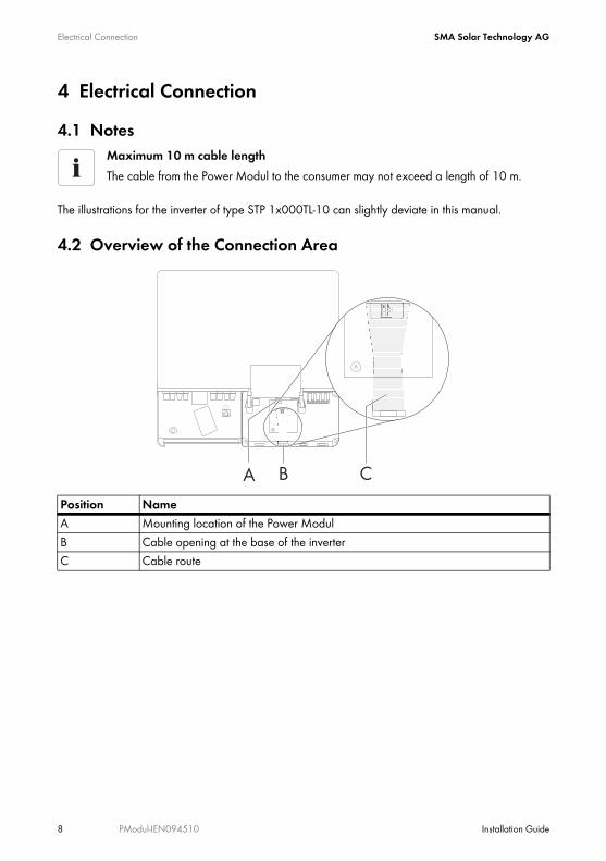
4 Electrical Connection4.1 Notes
The illustrations for the inverter of type STP 1x000TL-10 can slightly deviate in this manual.
4.2 Overview of the Connection Area
Maximum 10 m cable lengthThe cable from the Power Modul to the consumer may not exceed a length of 10 m.
Position NameA Mounting location of the Power ModulB Cable opening at the base of the inverterC Cable route
SMA Solar Technology AG Electrical Connection
Installation Guide PModul-IEN094510 9
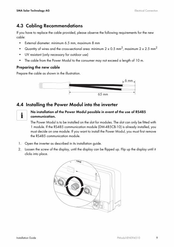
4.3 Cabling RecommendationsIf you have to replace the cable provided, please observe the following requirements for the new cable:
• External diameter: minimum 6.5 mm, maximum 8 mm• Quantity of wires and the cross-sectional area: minimum 2 x 0.5 mm2, maximum 2 x 2.5 mm2
• UV resistant (only necessary for outdoor use)• The cable from the Power Modul to the consumer may not exceed a length of 10 m.
Preparing the new cablePrepare the cable as shown in the illustration.
4.4 Installing the Power Modul into the inverter
1. Open the inverter as described in its installation guide.2. Loosen the screw of the display, until the display can be flipped up. Flip up the display until it
clicks into place.
No installation of the Power Modul possible in event of the use of RS485 communication.The Power Modul is to be installed on the slot for modules. The slot can only be fitted with 1 module. If the RS485 communication module (DM-485CB-10) is already installed, you must decide on one module. If you want to install the Power Modul, you must first remove the RS485 communication module.

Electrical Connection SMA Solar Technology AG
10 PModul-IEN094510 Installation Guide
3. Press the filler plug out of the second cable opening on the left side.
4. Unscrew counter nut from the delivered cable gland.
5. Place the cable gland into the enclosure opening of the inverter and fastening it along with the counter nut from inside.

SMA Solar Technology AG Electrical Connection
Installation Guide PModul-IEN094510 11
6. Unscrew the nut of the cable gland from the inverter.
7. Press the seal out of the cable gland.
8. Open spring-type terminals of the Power Modul.

Electrical Connection SMA Solar Technology AG
12 PModul-IEN094510 Installation Guide
9. Install the Power Modul as shown in the illustration and push the ribbon cable behind the display upwards.
10. Flip down the display.11. Hold the display and push the ribbon cable onto the multiple socket until the side clamps
tangibly reseal the plug.
12. Flip up the display until it clicks into place.

SMA Solar Technology AG Electrical Connection
Installation Guide PModul-IEN094510 13
13. Secure the Power Modul with the screw.
14. Remove one of the filler plugs from the seal.
15. Plug the cable through the nut and the seal.
16. Insert the end of the cable through the cable gland in the inverter.
17. Push the seal into the cable gland.18. Loosely screw on the nut of the cable gland.19. Connect the wires to the terminals of the socket. The polarity is arbitrary.20. Close the spring-type terminals.
Electrical Connection SMA Solar Technology AG
14 PModul-IEN094510 Installation Guide
21. Screw the nuts tightly onto the cable gland until the cable can no longer be moved. If necessary, screw the counter nut more tightly.
22. Flip down the display.23. Screw the display screw tightly in place.24. Close the inverter as described in its installation guide.25. Connect the other end of the cable to the consumer, as described in the consumer manual.26. Commission the inverter as described in its manual.☑ The Power Modul is installed.

SMA Solar Technology AG Decommissioning
Installation Guide PModul-IEN094510 15
5 Decommissioning5.1 Removing the Power Modul from the inverter1. Open the inverter as described in its installation guide.2. Remove the plug for the ribbon cable of the Power Modul as shown in the illustration.
3. Loosen the screw of the display, until the display can be flipped up. Flip up the display until it clicks into place.
4. Unscrew the nut of the cable gland.5. Loosen the screw of the Power Modul, until the Power Modul can be removed. Remove the
Power Modul.6. Open the spring-type terminals of the connector on the module and remove all wires.7. Pull the cable out of the inverter.8. Remove the nut and the seal of the cable gland from the cable.9. Unscrew the counter nut and remove the cable gland.
10. Close the enclosure opening with the filler plug for the enclosure feed openings.11. Close the inverter as described in its installation guide.☑ The Power Modul is uninstalled.

Technical Data SMA Solar Technology AG
16 PModul-IEN094510 Installation Guide
6 Technical DataInterfacesInverter Ribbon cableConsumer 2 pole spring-type terminalsPower supplyPower consumption depending on consumer, maximum 2.5 WAmbient conditions during storage and transportAmbient temperature -40 °C to +70 °CRelative humidity 10 % to 95 %, non-condensingGeneral dataElectric output 12 V DC ±10 %, maximum 145 mADimensions (B/H/T) 73 mm / 88 mm / 34 mmWeight 71 gMounting location in the inverter

SMA Solar Technology AG Contact
Installation Guide PModul-IEN094510 17
7 ContactIf you have technical problems concerning our products, contact the SMA Serviceline. We require the following information in order to provide you with the necessary assistance:
• Inverter type• Inverter serial number• Serial number of the Power Modul• Version of the Power Modul
SMA Solar Technology AGSonnenallee 134266 Niestetal, Germanywww.SMA.de
SMA Serviceline Inverters: +49 561 9522 1499Communication: +49 561 9522 2499Fax: +49 561 9522 4699E-Mail: [email protected]

Legal Restrictions SMA Solar Technology AG
18 PModul-IEN094510 Installation Guide
The information contained in this document is the property of SMA Solar Technology AG. Publishing its content, either partially or in full, requires the written permission of SMA Solar Technology AG. Any internal company copying of the document for the purposes of evaluating the product or its correct implementation is allowed and does not require permission.
Exclusion of liabilityThe general terms and conditions of delivery of SMA Solar Technology AG shall apply.The content of these documents is continually checked and amended, where necessary. However, discrepancies cannot be excluded. No guarantee is made for the completeness of these documents. The latest version is available online at www.SMA.de or from the usual sales channels.Guarantee or liability claims for damages of any kind are excluded if they are caused by one or more of the following: • Damages during transportation• Improper or inappropriate use of the product• Operating the product in an unintended environment• Operating the product whilst ignoring relevant, statutory safety regulations in the deployment location• Ignoring safety warnings and instructions contained in all documents relevant to the product• Operating the product under incorrect safety or protection conditions• Altering the product or supplied software without authority• The product malfunctions due to operating attached or neighboring devices beyond statutory limit values• In case of unforeseen calamity or force majeureThe use of supplied software produced by SMA Solar Technology AG is subject to the following conditions:• SMA Solar Technology AG rejects any liability for direct or indirect damages arising from the use of software developed by
SMA Solar Technology AG. This also applies to the provision or non-provision of support activities.• Supplied software not developed by SMA Solar Technology AG is subject to the respective licensing and liability agreements
of the manufacturer.
SMA Factory WarrantyThe current guarantee conditions come enclosed with your device. These are also available online at www.SMA.de and can be downloaded or are available on paper from the usual sales channels if required.
TrademarksAll trademarks are recognized even if these are not marked separately. Missing designations do not mean that a product or brand is not a registered trademark.The Bluetooth® word mark and logos are registered trademarks owned by Bluetooth SIG, Inc. and any use of such marks by SMA Solar Technology is under license.SMA Solar Technology AGSonnenallee 134266 NiestetalGermanyTel. +49 561 9522-0Fax +49 561 9522-100www.SMA.deE-Mail: [email protected]© 2004 to 2010 SMA Solar Technology AG. All rights reserved


SMA Solar Technology AG
www.SMA.de