Embed Size (px)
Citation preview
1
Solar Collector Technology (Solar Collection 101)
Solar Calorimetry Laboratory
Dept. of Mechanical and Materials Engineering
Queen’s University
Reference Material
•“Planning and Installing Solar Thermal Systems”, James &
James/Earthscan, London, UK
•Medium Temperature Collectors, State of the Art within Task 33/IV,
Subtask C, Werner Weiss, AEE INTEC, Matthias Rommel,
Fraunhofer ISE
• “Solar Engineering of Thermal Processes”, Duffie & Beckman,
John Wiley & Sons Inc.,
•Federal Technology Alert, Parabolic-Trough Solar Water Heating,
Produced for the U.S. Department of Energy (DOE)
by the National Renewable Energy Laboratory, 2000
2
Solar Collector Technology
1.Solar Resource
2.Solar Collector Basics
3.Thermal Performance
4.Solar Collector Selection
5.Conclusion
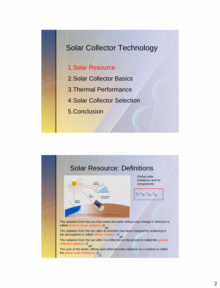
Solar Resource: Definitions Global solar
irradiance and its
components
The radiation from the sun that meets the earth without any change in direction is
called direct or beam radiation, Gdir
.
The radiation from the sun after its direction has been changed by scattering in
the atmosphere is called diffuse radiation, Gdif
.
The radiation from the sun after it is reflected on the ground is called the ground
reflected radiation, Gref
.
The sum of the beam, diffuse and reflected solar radiation on a surface is called
the global solar irradiance, GG
.
GG
= Gdir +
Gdif +
Gref
From “Planning and Installing Solar Thermal Systems”, James & James/Earthscan, London, UK
3
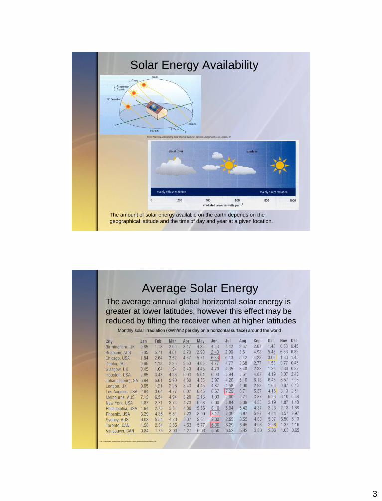
Solar Energy Availability
The amount of solar energy available on the earth depends on the
geographical latitude and the time of day and year at a given location.
From “Planning and Installing Solar Thermal Systems”, James & James/Earthscan, London, UK
Average Solar Energy
Monthly solar irradiation (kWh/m2 per day on a horizontal surface) around the world
The average annual global horizontal solar energy is
greater at lower latitudes, however this effect may be
reduced by tilting the receiver when at higher latitudes
From “Planning and Installing Solar Thermal Systems”, James & James/Earthscan, London, UK
4
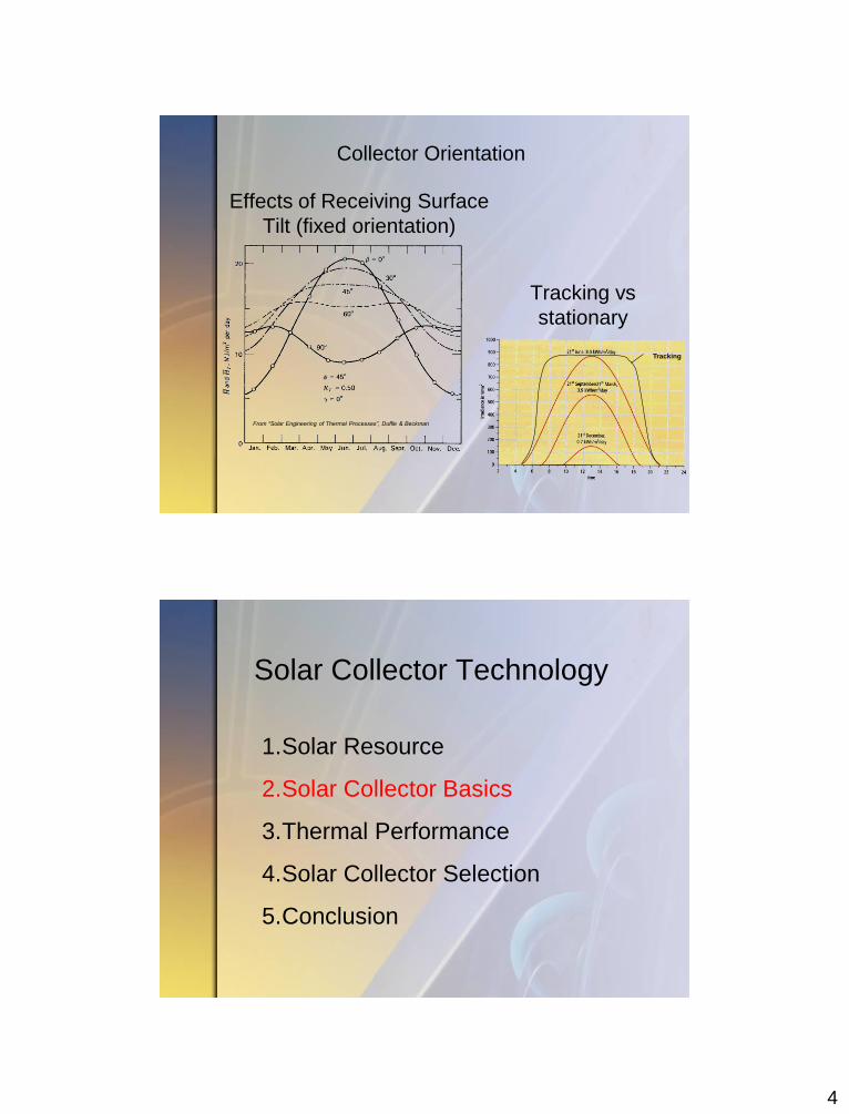
Effects of Receiving Surface
Tilt (fixed orientation)
From “Solar Engineering of Thermal Processes”, Duffie & Beckman
Tracking vs
stationary
Collector Orientation
Tracking
Solar Collector Technology
1.Solar Resource
2.Solar Collector Basics
3.Thermal Performance
4.Solar Collector Selection
5.Conclusion
5
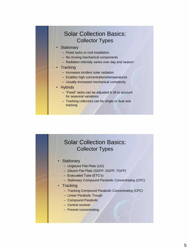
Solar Collection Basics: Collector Types
• Stationary
– Fixed racks or roof installation
– No moving mechanical components
– Radiation intensity varies over day and season
• Tracking
– Increases incident solar radiation
– Enables high concentrations/temperatures
– Usually increased mechanical complexity
• Hybrids
– “Fixed” racks can be adjusted in tilt to account
for seasonal variations
– Tracking collectors can be single or dual axis
tracking
Solar Collection Basics: Collector Types
• Stationary
– Unglazed Flat Plate (UG)
– Glazed Flat Plate (SGFP, DGFP, TGFP)
– Evacuated Tube (ETC’s)
– Stationary Compound Parabolic Concentrating (CPC)
• Tracking
– Tracking Compound Parabolic Concentrating (CPC)
– Linear Parabolic Trough
– Compound Parabolic
– Central receiver
– Fresnel concentrating
6
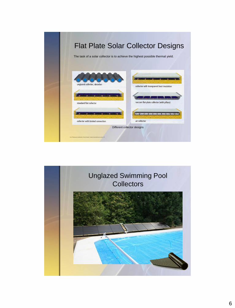
Flat Plate Solar Collector Designs
Different collector designs
The task of a solar collector is to achieve the highest possible thermal yield.
From “Planning and Installing Solar Thermal Systems”, James & James/Earthscan, London, UK
Unglazed Swimming Pool
Collectors
7
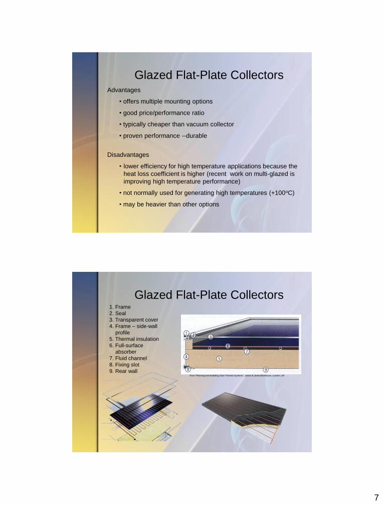
Glazed Flat-Plate Collectors Advantages
• offers multiple mounting options
• good price/performance ratio
• typically cheaper than vacuum collector
• proven performance --durable
Disadvantages
• lower efficiency for high temperature applications because the
heat loss coefficient is higher (recent work on multi-glazed is
improving high temperature performance)
• not normally used for generating high temperatures (+100oC)
• may be heavier than other options
Glazed Flat-Plate Collectors 1. Frame
2. Seal
3. Transparent cover
4. Frame – side-wall
profile
5. Thermal insulation
6. Full-surface
absorber
7. Fluid channel
8. Fixing slot
9. Rear wall From “Planning and Installing Solar Thermal Systems”, James & James/Earthscan, London, UK
8
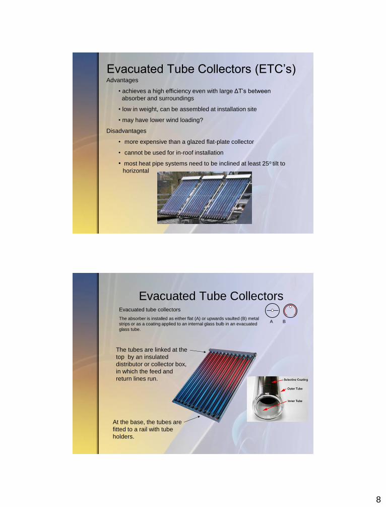
Evacuated Tube Collectors (ETC’s) Advantages
• achieves a high efficiency even with large ΔT’s between
absorber and surroundings
• low in weight, can be assembled at installation site
• may have lower wind loading?
Disadvantages
• more expensive than a glazed flat-plate collector
• cannot be used for in-roof installation
• most heat pipe systems need to be inclined at least 25o tilt to
horizontal
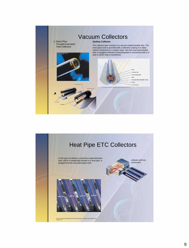
Evacuated Tube Collectors Evacuated tube collectors
The absorber is installed as either flat (A) or upwards vaulted (B) metal
strips or as a coating applied to an internal glass bulb in an evacuated
glass tube.
A B
The tubes are linked at the
top by an insulated
distributor or collector box,
in which the feed and
return lines run.
At the base, the tubes are
fitted to a rail with tube
holders.
9
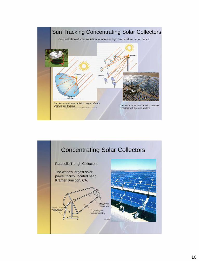
Vacuum Collectors 1. Direct Flow
Through Evacuated
Tube Collectors
Sydney Collector
The collector tube consists of a vacuum-sealed double tube. The
inner glass bulb is provided with a selective coating of a metal
carbon compound on a copper base. Into this evacuated double
tube is plugged a thermal conducting plate in connection with a U-
tube to which heat is transferred.
From “Planning and Installing Solar Thermal Systems”, James & James/Earthscan, London, UK
Heat Pipe ETC Collectors
In this type of collector a selective coated absorber
strip, which is metallically bonded to a heat pipe, is
plugged into the evacuated glass tube.
collector with dry
connection
From “Planning and Installing Solar Thermal Systems”, James & James/Earthscan,
London, UK
10
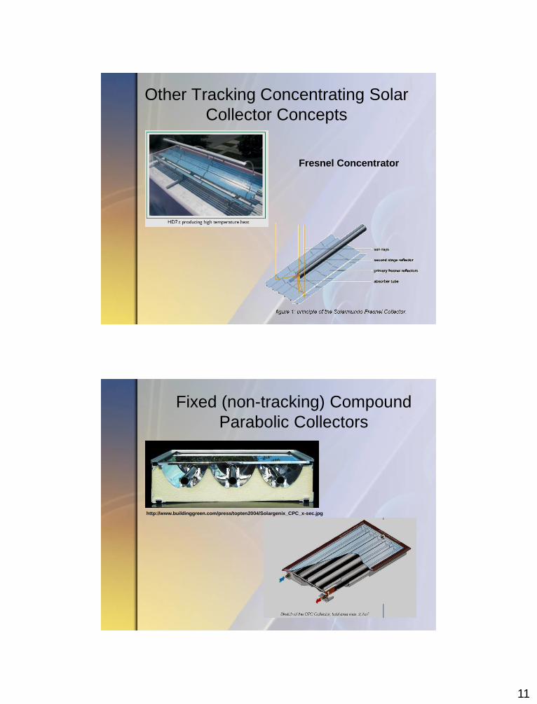
Sun Tracking Concentrating Solar Collectors Concentration of solar radiation to increase high temperature performance
Concentration of solar radiation: single reflector
with two-axis tracking Concentration of solar radiation: multiple
reflectors with two-axis tracking From “Planning and Installing Solar Thermal Systems”, James & James/Earthscan, London, UK
Parabolic Trough Collectors
The world's largest solar
power facility, located near
Kramer Junction, CA.
Concentrating Solar Collectors
11
Other Tracking Concentrating Solar
Collector Concepts
Fresnel Concentrator
Fixed (non-tracking) Compound
Parabolic Collectors
http://www.buildinggreen.com/press/topten2004/Solargenix_CPC_x-sec.jpg
12
Solar Collector Technology
1.Solar Resource
2.Solar Collector Basics
3.Thermal Performance
4.Solar Collector Selection
5.Conclusion
Solar Collector Efficiency
A
o
Q
G
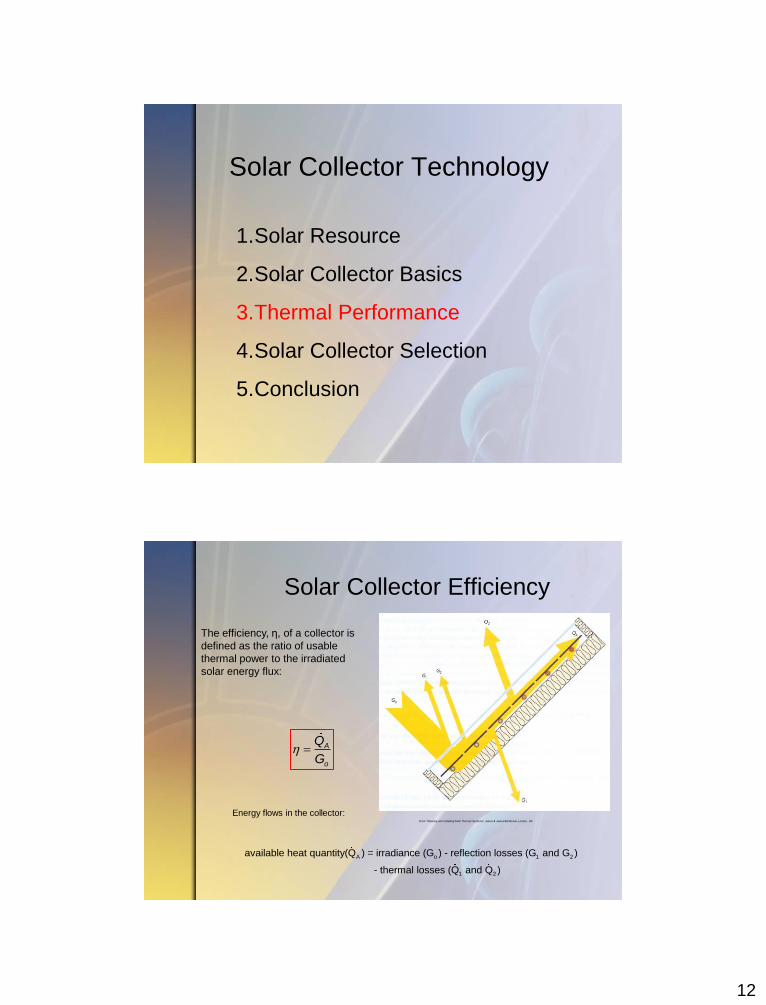
Energy flows in the collector:
The efficiency, η, of a collector is
defined as the ratio of usable
thermal power to the irradiated
solar energy flux:
A o 1 2
1 2
available heat quantity(Q ) = irradiance (G ) - reflection losses (G and G )
- thermal losses (Q and Q )
From “Planning and Installing Solar Thermal Systems”, James & James/Earthscan, London, UK
13
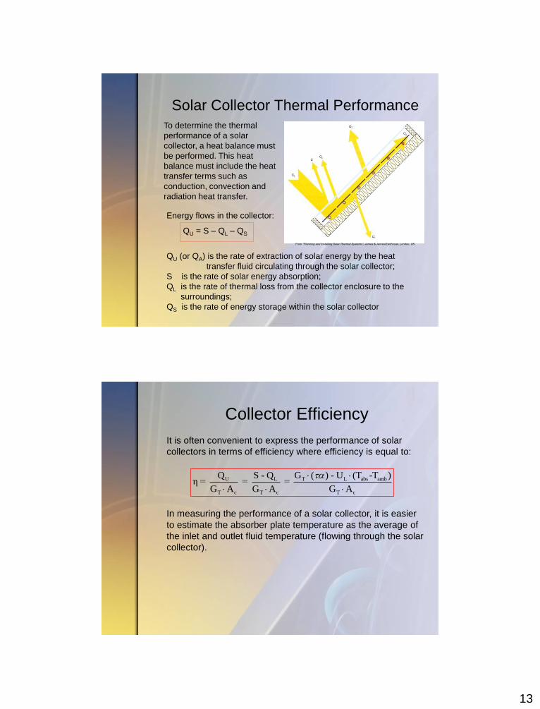
Solar Collector Thermal Performance
Energy flows in the collector:
QU = S – QL – QS
QU (or QA) is the rate of extraction of solar energy by the heat
transfer fluid circulating through the solar collector;
S is the rate of solar energy absorption;
QL is the rate of thermal loss from the collector enclosure to the
surroundings;
QS is the rate of energy storage within the solar collector
To determine the thermal
performance of a solar
collector, a heat balance must
be performed. This heat
balance must include the heat
transfer terms such as
conduction, convection and
radiation heat transfer.
From “Planning and Installing Solar Thermal Systems”, James & James/Earthscan, London, UK
Collector Efficiency
U T L abs ambL
T c T c T c
Q G ( ) - U (T -T )S - Qη = = =
G A G A G A
It is often convenient to express the performance of solar
collectors in terms of efficiency where efficiency is equal to:
In measuring the performance of a solar collector, it is easier
to estimate the absorber plate temperature as the average of
the inlet and outlet fluid temperature (flowing through the solar
collector).
14
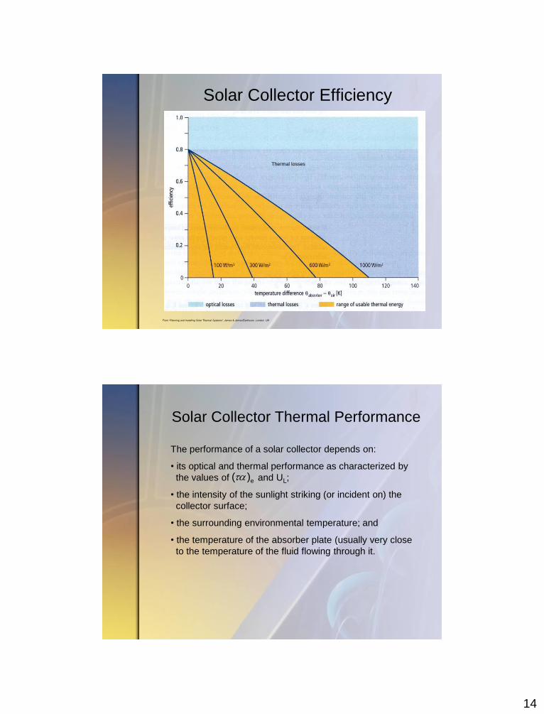
Solar Collector Efficiency
From “Planning and Installing Solar Thermal Systems”, James & James/Earthscan, London, UK
Thermal losses
Solar Collector Thermal Performance
The performance of a solar collector depends on:
• its optical and thermal performance as characterized by
the values of and UL;
• the intensity of the sunlight striking (or incident on) the
collector surface;
• the surrounding environmental temperature; and
• the temperature of the absorber plate (usually very close
to the temperature of the fluid flowing through it.
e( )
15
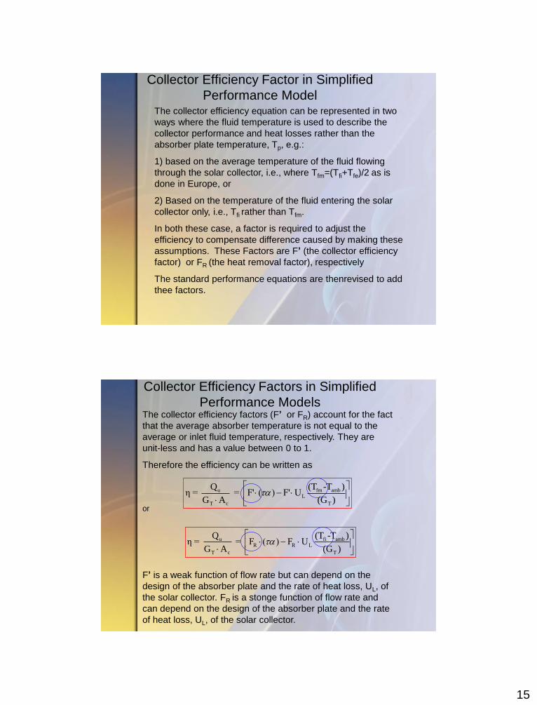
Collector Efficiency Factor in Simplified
Performance Model The collector efficiency equation can be represented in two
ways where the fluid temperature is used to describe the
collector performance and heat losses rather than the
absorber plate temperature, Tp, e.g.:
1) based on the average temperature of the fluid flowing
through the solar collector, i.e., where Tfm=(Tfi+Tfe)/2 as is
done in Europe, or
2) Based on the temperature of the fluid entering the solar
collector only, i.e., Tfi rather than Tfm.
In both these case, a factor is required to adjust the
efficiency to compensate difference caused by making these
assumptions. These Factors are F’ (the collector efficiency
factor) or FR (the heat removal factor), respectively
The standard performance equations are thenrevised to add
thee factors.
Collector Efficiency Factors in Simplified
Performance Models The collector efficiency factors (F’ or FR) account for the fact
that the average absorber temperature is not equal to the
average or inlet fluid temperature, respectively. They are
unit-less and has a value between 0 to 1.
Therefore the efficiency can be written as
or
F’ is a weak function of flow rate but can depend on the
design of the absorber plate and the rate of heat loss, UL, of
the solar collector. FR is a stonge function of flow rate and
can depend on the design of the absorber plate and the rate
of heat loss, UL, of the solar collector.
u fm ambL
T c T
Q (T -T )η = = F' ( ) F' U
G A (G )
u fi ambR R L
T c T
Q (T -T )η = = F ( ) F U
G A (G )
16
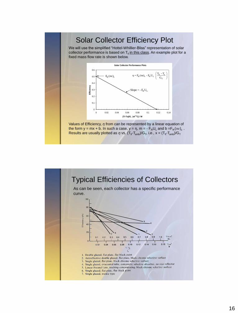
We will use the simplified “Hottel-Whillier-Bliss” representation of solar
collector performance is based on Tfi in this class. An example plot for a
fixed mass flow rate is shown below.
Values of Efficiency, η from can be represented by a linear equation of
the form y = mx + b. In such a case, y = η, m = - FRUL and b =FR .
Results are usually plotted as η vs. (Tfi-Tamb)/GT, i.e., x = (Tfi-Tamb)/GT
Solar Collector Efficiency Plot
Solar Collector Performance Plots
0
0.1
0.2
0.3
0.4
0.5
0.6
0 0.02 0.04 0.06 0.08 0.1 0.12 0.14
(Ti-Ta)/G, (m2 oC) / W
Eff
icie
ncy
eRF ( )afi
eR R L
T
T - Tη = F (τα) - F U
G
R LSlope = - F U
e( )
Typical Efficiencies of Collectors As can be seen, each collector has a specific performance
curve.
17
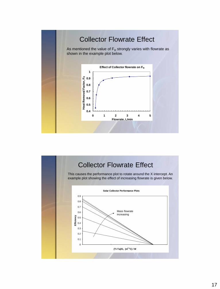
Collector Flowrate Effect
As mentioned the value of FR strongly varies with flowrate as
shown in the example plot below.
Effect of Collector flowrate on FR
0.4
0.5
0.6
0.7
0.8
0.9
1
0 1 2 3 4 5
Flowrate, L/min
He
at
Re
mo
va
l F
ac
tor,
FR
This causes the performance plot to rotate around the X intercept. An
example plot showing the effect of increasing flowrate is given below.
Collector Flowrate Effect
Solar Collector Performance Plots
0
0.1
0.2
0.3
0.4
0.5
0.6
0.7
0.8
0.9
(Ti-Ta)/G, (m2 oC) / W
Eff
icie
ncy
Mass flowrate
increasing
18
Solar Collector Performance Plots
0
0.1
0.2
0.3
0.4
0.5
0.6
0.7
0.8
0.9
(Ti-Ta)/G, (m2 oC) / W
Eff
icie
ncy
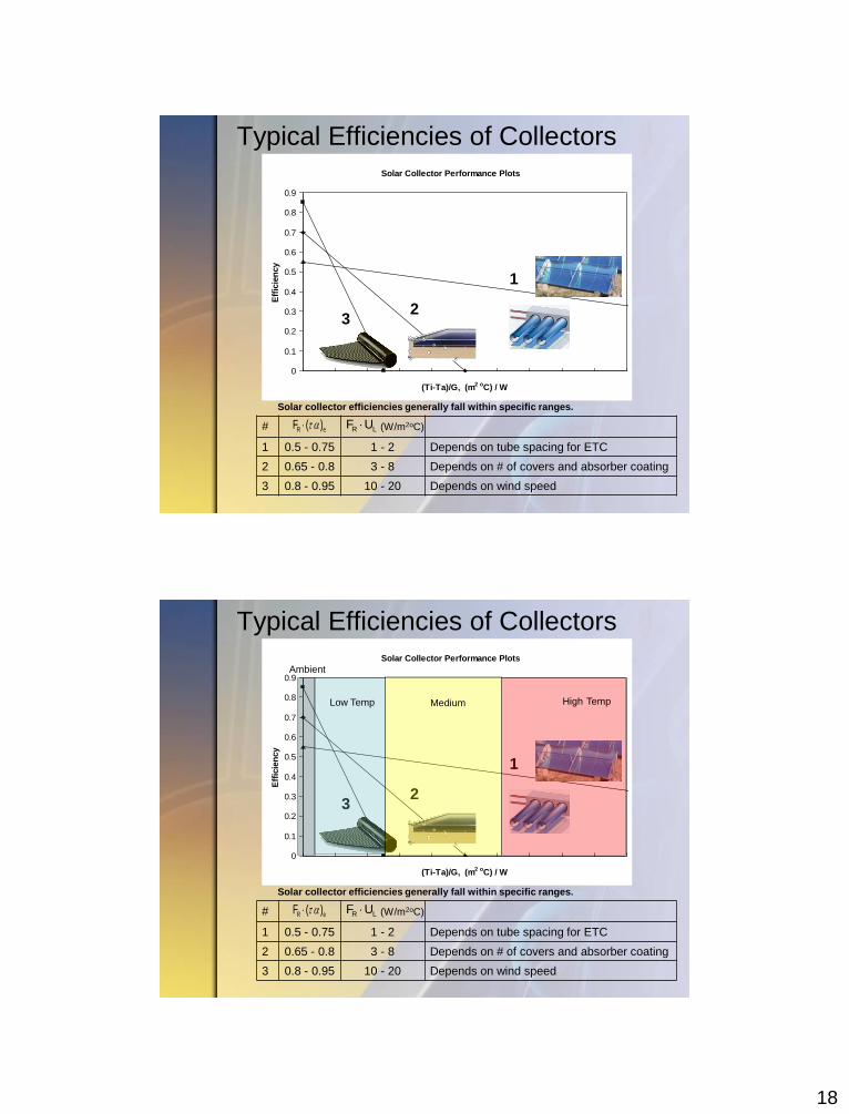
Typical Efficiencies of Collectors
# (W/m2oC)
1 0.5 - 0.75 1 - 2 Depends on tube spacing for ETC
2 0.65 - 0.8 3 - 8 Depends on # of covers and absorber coating
3 0.8 - 0.95 10 - 20 Depends on wind speed
3 - Unglazed Swimming
Pool Absorber
2 - Glazed Flat
Plate Collector
1 - Vacuum Tube
Collector
R eF ( ) R LF U
Solar collector efficiencies generally fall within specific ranges.
3
1
2
Solar Collector Performance Plots
0
0.1
0.2
0.3
0.4
0.5
0.6
0.7
0.8
0.9
(Ti-Ta)/G, (m2 oC) / W
Eff
icie
ncy
Typical Efficiencies of Collectors
# (W/m2oC)
1 0.5 - 0.75 1 - 2 Depends on tube spacing for ETC
2 0.65 - 0.8 3 - 8 Depends on # of covers and absorber coating
3 0.8 - 0.95 10 - 20 Depends on wind speed
3 - Unglazed Swimming
Pool Absorber
2 - Glazed Flat
Plate Collector
1 - Vacuum Tube
Collector
R eF ( ) R LF U
Solar collector efficiencies generally fall within specific ranges.
3
1
2
Ambient
Low Temp Medium High Temp
19
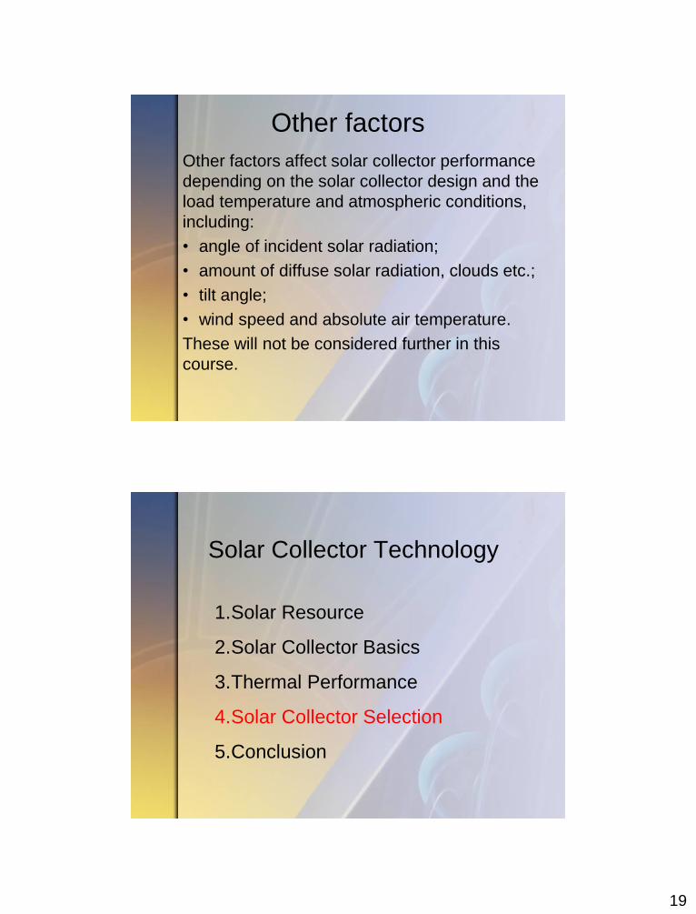
Other factors
Other factors affect solar collector performance
depending on the solar collector design and the
load temperature and atmospheric conditions,
including:
• angle of incident solar radiation;
• amount of diffuse solar radiation, clouds etc.;
• tilt angle;
• wind speed and absolute air temperature.
These will not be considered further in this
course.
Solar Collector Technology
1.Solar Resource
2.Solar Collector Basics
3.Thermal Performance
4.Solar Collector Selection
5.Conclusion
20
Reference Area When comparing collectors, the reference area is
important – that is, the surface area from which the
collector’s characteristics values are drawn. For North
American ratings, the reference area is equal to the gross
area.
However, solar collector test results and efficiency
characteristics, may be shown with respect to aperture,
absorber or gross area making comparisons between
products difficult.
Efficiency based on absorber or aperture will be higher
than that based on gross area although delivered energy
will be the same.
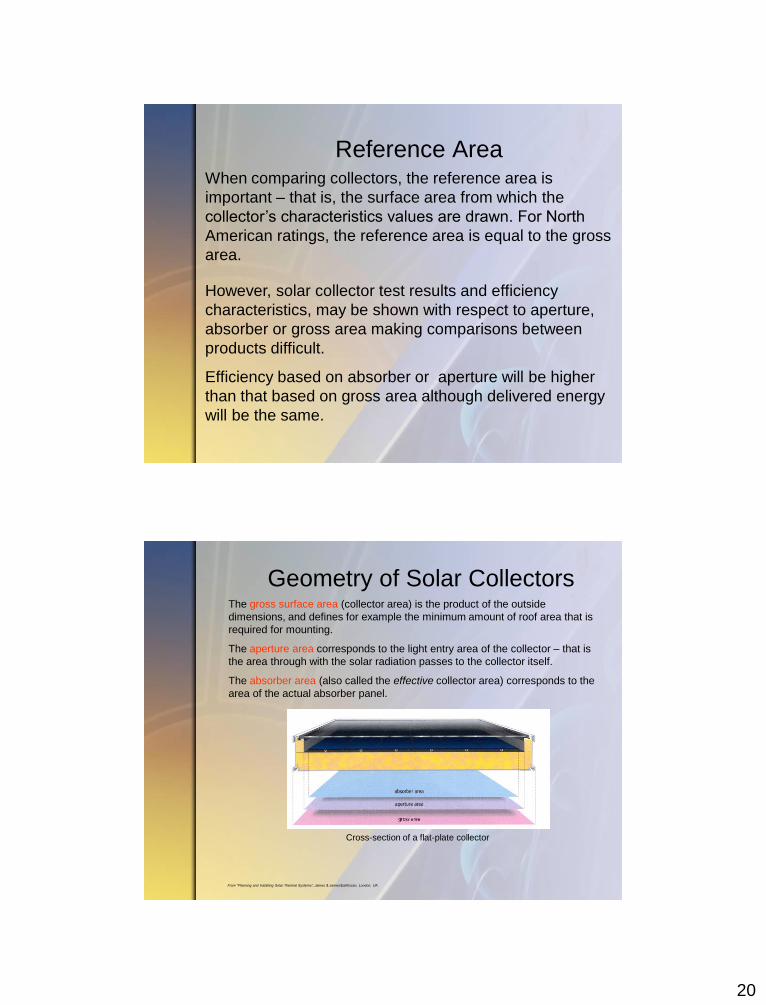
Geometry of Solar Collectors
Cross-section of a flat-plate collector
The gross surface area (collector area) is the product of the outside
dimensions, and defines for example the minimum amount of roof area that is
required for mounting.
The aperture area corresponds to the light entry area of the collector – that is
the area through with the solar radiation passes to the collector itself.
The absorber area (also called the effective collector area) corresponds to the
area of the actual absorber panel.
From “Planning and Installing Solar Thermal Systems”, James & James/Earthscan, London, UK
21
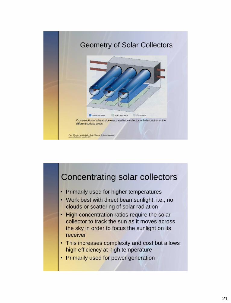
Geometry of Solar Collectors
Cross-section of a heat-pipe evacuated tube collector with description of the
different surface areas
From “Planning and Installing Solar Thermal Systems”, James &
James/Earthscan, London, UK
Concentrating solar collectors
• Primarily used for higher temperatures
• Work best with direct bean sunlight, i.e., no
clouds or scattering of solar radiation
• High concentration ratios require the solar
collector to track the sun as it moves across
the sky in order to focus the sunlight on its
receiver
• This increases complexity and cost but allows
high efficiency at high temperature
• Primarily used for power generation
22
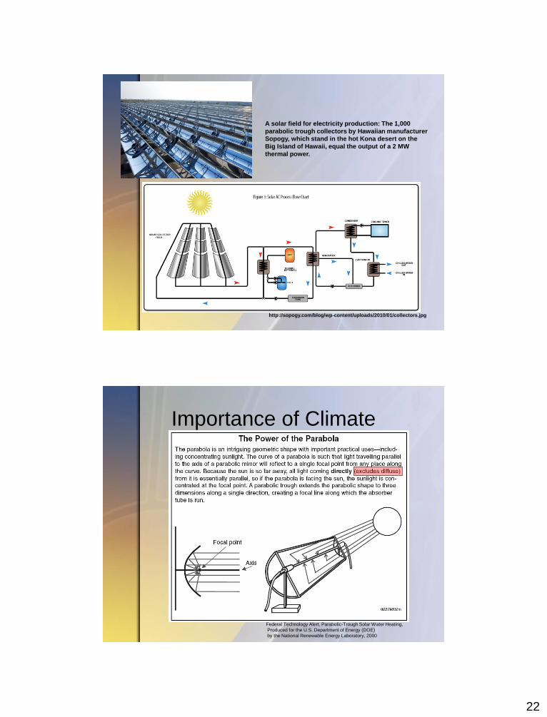
http://sopogy.com/blog/wp-content/uploads/2010/01/collectors.jpg
A solar field for electricity production: The 1,000
parabolic trough collectors by Hawaiian manufacturer
Sopogy, which stand in the hot Kona desert on the
Big Island of Hawaii, equal the output of a 2 MW
thermal power.
Importance of Climate
Federal Technology Alert, Parabolic-Trough Solar Water Heating,
Produced for the U.S. Department of Energy (DOE)
by the National Renewable Energy Laboratory, 2000
23
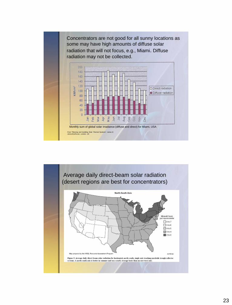
Concentrators are not good for all sunny locations as
some may have high amounts of diffuse solar
radiation that will not focus, e.g., Miami. Diffuse
radiation may not be collected.
Monthly sum of global solar irradiance (diffuse and direct) for Miami, USA
From “Planning and Installing Solar Thermal Systems”, James &
James/Earthscan, London, UK
Average daily direct-beam solar radiation
(desert regions are best for concentrators)
24
Solar collector selection
• Depends on end-use temperature and
ambient temperature
• Climatic conditions that affect the quantity of
beam-irradiance are important
• Durability issues such as thermal shock,
stagnation temperatures
• Installation requirements and complexity,
e.g., racking, tracking mechanisms
• Cost per unit energy at the required
temperature level
Solar collector selection
• Ultimately the choice of the best solar
collector depends on climate, location
and system aspects so a full system
simulation should be undertaken!
25
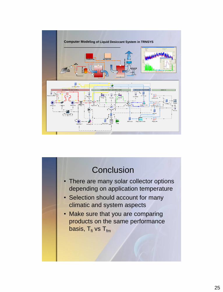
Computer Modeling of Liquid Desiccant System in TRNSYS
Conclusion
• There are many solar collector options
depending on application temperature
• Selection should account for many
climatic and system aspects
• Make sure that you are comparing
products on the same performance
basis, Tfi vs Tfm

26
The End