Embed Size (px)
Citation preview
1
Solar and Heat Pump Systems: parallel vs series configurations
analysis
J. Vega1*, C. Cuevas2
(1) Departamento de Ingeniería Mecánica - Universidad de Concepción
Edmundo Larenas 219 - Concepción – Chile
(2) Departamento de Ingeniería Mecánica - Universidad de Concepción
Edmundo Larenas 219 - Concepción – Chile
1. ABSTRACT
This paper presents simulations of a Solar and Heat pump System (SHP) system for Domestic Hot
Water (DHW) preparation. Two system configurations are designed for covering the heat demand.
These, can switch between parallel and series operation. Thus, Configuration “A” consists in using
a heat pump with two evaporators that alternate: one to work as an air-to-water heat pump (HP)
and the other to operate as a water-to-water HP using the solar collector’s (SC) heat. Configuration
“B” implements a heat exchanger in the air-to-water HP that can pre-heat the air, using solar
energy. These system configurations are modelled in the TRNSYS 17 environment for evaluating
system’s performance in different climates and with different SCs. The control system applies a
switching criterion between parallel or series operation modes, based primarily on the available
solar irradiation. Results show that individual performance figures of the HP and the SCs increase.
Nonetheless, the Seasonal Performance Factor (SPF) of the overall system decreases in most case
studies (5.58 to 4.55 in the worst case). It is emphasized that the applied switching criterion does
not force the SCs to increase their operational time by cooling them with the HP. In consequence,
there is still potential solar energy unused that the series operation could seize.
Keywords: Solar and heat pump systems, series configuration, parallel configuration, control
systems
2. INTRODUCTION
In central and southern Chile, residential heating systems are mainly based on wood, paraffin or
liquefied petroleum gas stoves. Among these, wood is the most frequently used fuel because of
its lower price and wide availability. Unfortunately, the combustion of wood is the main source
of air pollution during the winter period, with several cities declared as saturated by airborne
pollution. In the case of the domestic hot water, it is mainly heated by the combustion of liquefied
petroleum gas or natural gas. Even if for this case the pollution concernf is less severe, there is
still a constraint related to the cost of the fuels, proven to be highly sensitive to past energy crises.
These problems motivate the present study to evaluate the performance of alternative, more
efficient, and less contaminant technologies like heat pumps combined with solar collectors. These
are known as Solar and Heat Pump Systems (SHP systems).
SHP systems have been widely studied in the literature, especially by IEA SHC Task 44. As said,
they combine heat pumps with solar thermal technology, typically solar thermal collectors, to
supply energy demands on Domestic Hot Water (DHW) and Space Heating (SH). To achieve this
, these systems usually need an energy storage: hot water stratified storage tanks appear as the
2
more frequent and market available for this function. Nonetheless, multiple systems architectures
can result in combining these components. One way to categorize them, used by Task 44, is
according to the interaction of their components, which was fully described by Ruschenburg et al.
(2013). Thus, three main configurations are defined: parallel, series and regenerative. The
configuration is denoted as parallel if the SC and the HP independently supply useful energy.
Second, when collectors act as the heat source for the heat pump, either as exclusive or additional
source, the configuration is denoted as series. Last, if the solar energy is used to warm and
maintain the main source of the heat pump, usually the ground, it is denoted as regenerative. The
energy performance of the SHP systems depends on several variables such as the building
characteristics, the heat pump components, the solar radiation, the ambient conditions, the energy
demand schedules, and of course, the overall systems components interaction. Regarding the last,
series configuration concept is of interest. It has been created to boost the individual performance
of both solar collectors and heat pump. In fact, if solar collectors are the HP’s heat source, then
they are chilled by it. Thus, at lower operational temperatures, they improve their performance by
reducing their convection heat losses to the ambient. On its side, heat pump’s Coefficient of
Performance (COP) benefits from working with a higher temperature heat source than the air or
ground would be. These are the foundations that motivate the present paper.
Most of the SHP systems performance analyses are developed using modelling and simulations
during a representative period. For the modelling, different kinds of approaches are proposed in
the literature, classified by Hadorn J.C (2015). Semi-empirical black box models are the most
popular approaches used to model conventional systems by giving sufficiently accurate results.
These models are executed in programs like TRNSYS, Energy-Plus, ESP-r, Insel or Matlab,
among others. Most of these component models are validated and it is assumed that the simulation
of the overall system is thus correct. Nonetheless, some authors warn that these SHP systems
simulated performance is rarely validated experimentally. This is remarked by Banister C. and
Collins M. (2015) in their literature survey. This may be explained by the complexity of the
systems and the costs associated to the instrumentation and to the measurements campaign.
Nonetheless, some studies are found with in-field measurements and good model validation. For
example, Fraga et al. (2017) validated the simulations for a SHP system including an ice storage
using one-year measurements from a pilot plant. On their side, Liu et al. (2014) have done in-field
measurements to determine a high-capacity SHP system performance for an office building, and
then used TRNSYS simulations to optimize its operational behaviour.
Regarding the expected results of a SHP simulation, sizing of the equipment is fundamental. In
particular, solar energy contribution will have great impact on the system Seasonal Performance
Factor (SPFsyst), the most important figure to compare. It is found that increasing the total solar
collector area is most likely going to increase SPFsyst, although the decrease of the total electric
consumption is asymptotic as a function of the SPFsyst increase, as shown by Fraga et al. (2017).
Then, in reasonably sized systems, the limit to the total solar collar collector’s area will always
respond to an economic criterion. For the evaluated systems in the climate of Geneva, the
mentioned author concluded that for Geneva’s weather, 3 m2 of solar collector per kW of heat
pump capacity is a good compromise between system size and system performance.
There is abundant literature regarding parallel systems. Systematic work was done by Carbonell
et al. (2014) to analyse potential electricity savings of parallel SHP systems compared to simple
Air-Source Heat Pumps (ASHP) and Ground-Source Heat Pumps (GSHP). Work has also been
done to investigate parallel SHP systems performance with improvements in the heat pump’s
cycle, such as the case of ASHP studied by Poppi et al. (2016). They developed a theoretical
3
analysis using TRNSYS for two different climates, using variable speed heat pumps, vapour
injection compressors, condensers integrated in the storage tank, between others.
Regarding the study of series configuration systems, some are just heat-pump-focused. Sun et al.
(2015) compared an air-source heat pump with a solar source heat pump in the highly
heterogeneous climate of Shanghai, China. In their case study, SPFHP was higher using series
configuration, which is what should be expected. Others focus their conclusions more in SC’s
performance increase when chilled by the heat pump, such as Sterling et al. (2012). They also
studied solar source heat pumps for DHW, predicting a solar fraction increase from 58% to 67%.
Tzivanidis et al. (2016) developed a parametric analysis in TRNSYS for three different heating
systems: a solar system, an ASHP and a solar source heat pump. They concluded the solar source
heat pump was more convenient than the air-source one. Nonetheless, no parallel configuration
was evaluated to compare its performance. Other complex systems using solar source heat pumps
have been evaluated with measurements and simulations, but with no direct comparison between
parallel and series configuration (Liu et al., 2014). Then, there are some innovative studies on
series SHP systems. Banister and Collins [13] proposed to improve a classical series system with
a dual tank solar source heat pump, which allowed to reduce the energy consumption from 60%
to 69% when this system was used with a solar collector area of 7.5 m2. They also noticed in their
literature survey that the general conclusion of solar assisted heat pump systems is that energy
savings exist in comparison to traditional solar domestic hot water systems. Other novel system
was developed by He et al. [14] in which a solar façade loop-heat-pipe was used as source for a
HP. The authors simulated the performance and compared their results with a test rig, concluding
an average thermal efficiency of the solar façade of 71% and an average COP of 4.93 that could
reach up to 6.14.
There is few but existing literature that compares parallel and series configuration directly. Lerch
et al. (2015) compared several SHP systems for heating and DHW; studying different kinds of
series configurations, including ice storages, air preheating by solar energy and refrigerant heating
by solar energy after the heat pump’s evaporator. Compared to a classical parallel configuration,
the results showed little system performance increase. In addition, using unglazed collectors as
source for the heat pumps, the system required to double the collector’s aperture area to achieve
a similar system performance.
Systems that work in a series configuration only have a disadvantage: if there is a heat demand
when there is not enough solar radiation, the heat pump’s performance would be low because of
poor heat exchange between the solar collectors and ambient air. Thus, dual source heat pumps
are interesting since they search to combine the best features of parallel and series configuration
SHP systems. In these, the heat pump can switch between using solar energy or, for example, air
source energy. Then, the control system for the heat pump’s operation mode switching criterion
is of high interest. Kaygusus K. (1995), managed to improve the overall system performance
using an air-source and solar-source heat pump in the climate of Trabzon, Turkey. For this, the
author implemented an operation mode switch criterion based on the collector’s outlet
temperature. Lazarrin M. (2012) deepened Kaygusus’s work stufdying ground source heat pumps
coupled with solar collectors, both systems with the capability to work in a series mode. He
concluded that in series mode, as expected, higher COP can be achieved, but there is often a lower
free (air+solar or ground+solar) energy fraction, requiring auxiliary energy more frequently. On
the other hand, Haller et al. (2011) described the potential of these dual source configurations.
The authors also focused in comparing a dual air-source and solar-source heat pump. It is shown
by theoretical analysis and dynamic system simulations that, there is a limit for the solar irradiation
on the collector field above which using collector heat for the evaporator of the heat pump instead
4
of using it directly is not advantageous. This irradiation limit (Glim) depends on the characteristic
performance curves of the solar collector and of the heat pump, as well as on the temperature
conditions of the heat sources and sinks. This can be used as a criterion for switching between
parallel and series operation mode. Thus, the authors concluded there is a high potential in
improving the system’s performance taking advantage of the additional running times the
collectors gain when chilled by the heat pump. It is important to notice that Haller’s criteria for
switching between parallel and series is based on idealized and steady state conditions. Hadorn
J.C (2015) warned that this does not consider the transient effect of thermal capacitances.
The present work is inspired by these last conclusions. The objective is to study SHP systems that
can conmute between parallel and series mode of operation. The hypothesis, derived from Haller
et al., consists in assuming that there exists a solar irradiation value Glim below which a SHP
system benefits the most if it operates in series mode exclusively. This is assumed valid for every
combination of flow temperature of the heat demand and ambient temperature. This hypothesis is
applied to two different system configurations. The hypothesis also implies that if in any of the
previous mentioned SHP systems a control system could switch between parallel and series
operation based on the available solar irradiation, then the SPFsyst would be optimized. On the
other side, a certain parallel system will have a determined amount of time in which solar
collectors effectively use available solar energy. So, could such the beforementioned control
strategy be beneficial without modifying the solar collectors runtimes? For testing this thesis, SHP
systems capable of switching its operation mode will be designed, modelled and simulated in
TRNSYS to assess their performance in typical meteorological years in 3 Chilean cities. The case
studies are derived from the heat demand of DHW and SH a medium rise Chilean residential
building that has already been used by Vega et al. (2018) for assessing SHP systems performance
for simple parallel systems. Nonetheless, the present paper focus its study just in the DHW heat
demand.
3. METHODOLOGY
A system for DHW coverage of a mid-rise residential building is assessed. The selected heat
demand to cover permits to evaluate the thesis in a somewhat high temperature load and with high
component’s thermal capacitance. High thermal capacitance on the Hot Water Storage Tank
(HWST) and SCs, allows covering Hadorn’s concerns on transient effects in the operation mode
switching criterion. The system is tested in two different configurations, denoted as A and B, each
of them capable of operating in parallel or series mode. Configuration A consists in a double
evaporator HP, that can use as its energy source ambient air or solar energy from the SC. On the
other hand, B configuration’s series operation consists in using solar heat to warm the air passing
though the heat pump. A simple solar radiation based criterion is applied based on different fixed
solar irradiations value, Glim,control, below which series operation will be activated. Thus, several
numerical simulation to determine system’s performance are carried on with different values of
Glim,control set aiming to find an irradiation value that would switch parallel and series operation in
an beneficial way.
3.1. Simulations boundary conditions
Regarding the boundary conditions of the simulations to test the studied systems, they can be
divided in two: climate conditions and heat demand profiles. It is aimed to get valuable
conclusions and performance indicators for the Chilean context. Then, to fully describe
simulations boundary conditions, selected city weathers will first be presented, then, the heat loads
and profiles that the SHP system seek to cover.
5
3.1.1. Climate boundary conditions.
The system covering the heat demand is evaluated in 3 different Chilean cities. First, Santiago is
chosen for being the most populated city in Chile. Then, two cities are selected in the southern,
and thus colder, regions of Chile: Concepcion, and Puerto Montt. Using different climate
conditions is of interest because an ideal Glim,control will depend on ambient temperature and will
also be reached at lower frequencies in southern cities. The characteristics of selected climate data
are summarized in Table 1.
Table 1: Chilean thermal zone classification (MINVU, 2007), Köppen climate classification
(Weatherbase, 2018) and climate data (Meteonorm, 2017) that characterize the selected weather
Santiago Concepción Puerto Montt
Chilean thermal
zone classification Zone 1 Zone 4 Zone 6
Köppen climate
classification
Csb (Mediterranean
climate) bordering
BSk (semi-arid
climate)
Csb (mediterranean
climate)
Cfb (marine west
coast climate)
Average annual
temperature 14.7 °C 12.5 °C 10.2 °C
Anual
solar irradiation on
a horizontal surface 1739 kWh/m2 1493 kWh/m2 1166 kWh/m2
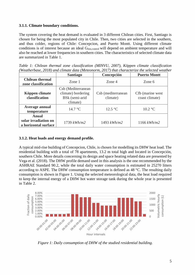
3.1.2. Heat loads and energy demand profile.
A typical mid-rise building of Concepcion, Chile, is chosen for modelling its DHW heat load. The
residential building with a total of 78 apartments, 13.2 m total high and located in Concepción,
southern Chile. More details concerning its design and space heating related data are presented by
Vega et al. (2018). The DHW profile demand used in this analysis is the one recommended by the
ASHRAE Standard 90.2, while the total daily water consumption is estimated in 25270 litters
according to ASPE. The DHW consumption temperature is defined as 48 °C. The resulting daily
consumption is shown in Figure 1. Using the selected meteorological data, the heat load required
to keep the internal energy of a DHW hot water storage tank during the whole year is presented
in Table 2.
Figure 1: Daily consumption of DHW of the studied residential building.
0
500
1000
1500
2000
0.00%1.00%2.00%3.00%4.00%5.00%6.00%7.00%8.00%
Vo
lum
etri
c h
ou
rly
con
sum
pti
on
(L)
Frac
tio
n o
f d
aily
co
nsu
mp
tio
n
Hour intervals

6
Table 2: Heat load for DHW preparation in each assesed climate.
Santiago Concepción Puerto Montt
Maximum capacity
demand 73.5 kW 76.6 kW 84.0 kW
Annual energy
demand 315 890 kWh 350 720 kWh 388 610 kWh
4. DESIGN AND MODELLING OF THE SHP SYSTEMS.
4.1. Overall design and system configurations.
Two different SHP system layouts are designed and modelled in TRNSYS: the SHP system in its
A and B configurations. Besides testing these layouts in different climates and control system
configurations, the use of two different types of solar collectors is proposed: Evacuated Tubes
Collectors (ETCs) and Unglazed Collectors (UC). From a certain point of view, these collectors’
performance profiles are opposed. ETC have a low optic performance, but low convective heat
losses when they operate at higher temperatures. In contrary, UC can have a higher thermal
efficiency if they are work at low temperatures, but this performance drops rapidly at higher
operating temperatures.
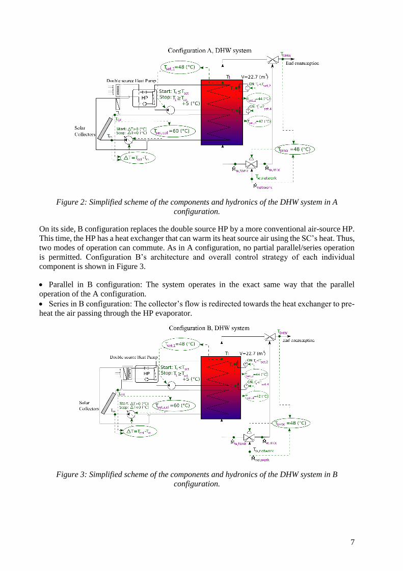
In the system, SCs and a HP deliver heat to a hot water storage tank via submerged helical heat
exchangers. The final consumer flow results in the controlled mixing by a thermostatic valve of
cold tap water with hot water from the storage tank. The storage temperature is maintained at 48
(°C) at the top by the solar collectors and the heat pump. SCs are active if they can gain energy
with the current conditions. On the other side, the heat pump’s control system is set to be active
if the solar collectors are not capable to maintain the HWST temperature.
Configuration A characterize itself for having a double evaporator HP, of which it can use just
one at the time. The first evaporator allows the HP to use air as its heat source. On the other side,
the second evaporator allows the HP to work as a water-water HP where the heat source fluid
corresponds to the SC’s working water. Then, configuration A has two modes of operation:
• Parallel operation: heat from the SCs is used directly in the HWST. If the HP is activated, it
uses its air-source evaporator.
• Series operation: heat from the SCs is used indirectly, as a heat source for the HP. Thus, the
HP uses its water source evaporator. In this mode, collectors are chilled, and the HP works with a
higher temperature source.
It is important to notice that no simultaneous mode of operation can occur; the system works either
as in parallel or in series mode. Configuration A’s architecture and overall control strategy of each
individual component is shown in Figure 2.
7
Figure 2: Simplified scheme of the components and hydronics of the DHW system in A
configuration.
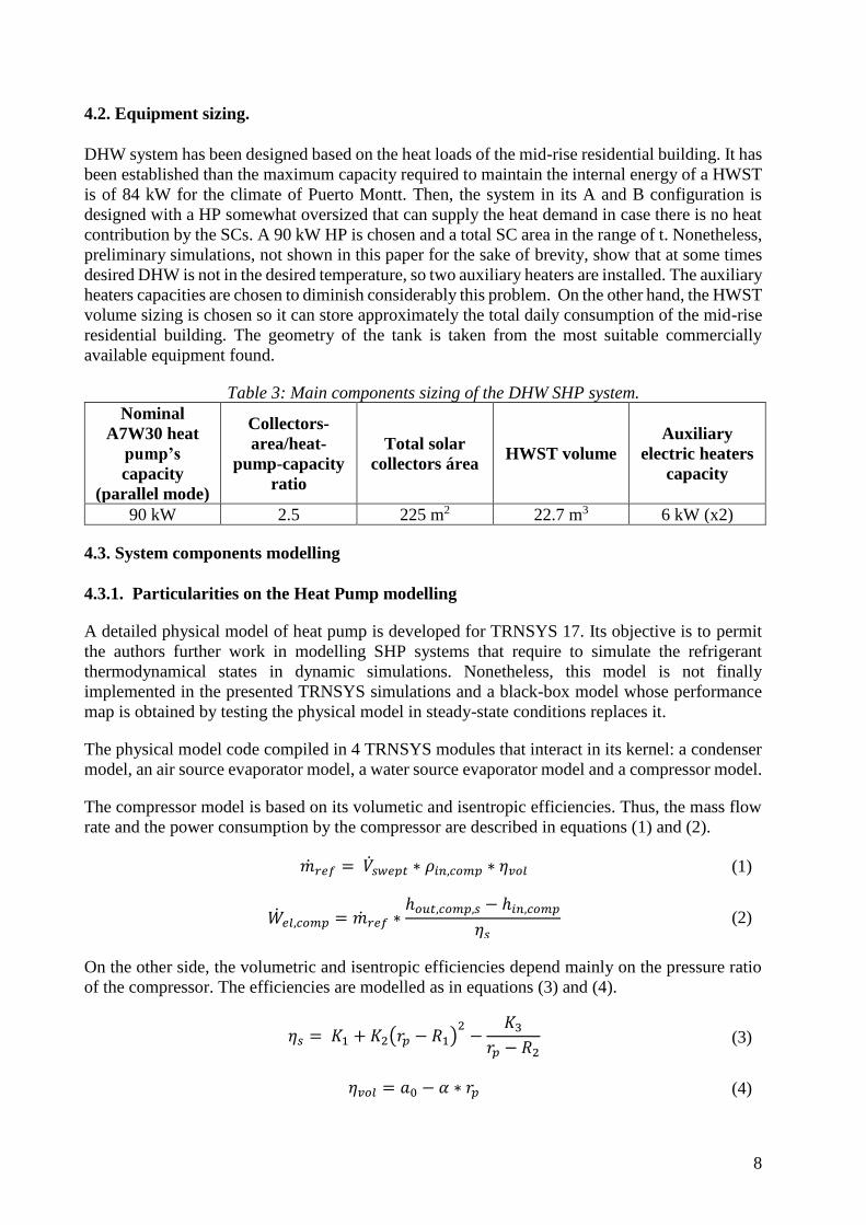
On its side, B configuration replaces the double source HP by a more conventional air-source HP.
This time, the HP has a heat exchanger that can warm its heat source air using the SC’s heat. Thus,
two modes of operation can commute. As in A configuration, no partial parallel/series operation
is permitted. Configuration B’s architecture and overall control strategy of each individual
component is shown in Figure 3.
• Parallel in B configuration: The system operates in the exact same way that the parallel
operation of the A configuration.
• Series in B configuration: The collector’s flow is redirected towards the heat exchanger to pre-
heat the air passing through the HP evaporator.
Figure 3: Simplified scheme of the components and hydronics of the DHW system in B
configuration.
8
4.2. Equipment sizing.
DHW system has been designed based on the heat loads of the mid-rise residential building. It has
been established than the maximum capacity required to maintain the internal energy of a HWST
is of 84 kW for the climate of Puerto Montt. Then, the system in its A and B configuration is
designed with a HP somewhat oversized that can supply the heat demand in case there is no heat
contribution by the SCs. A 90 kW HP is chosen and a total SC area in the range of t. Nonetheless,
preliminary simulations, not shown in this paper for the sake of brevity, show that at some times
desired DHW is not in the desired temperature, so two auxiliary heaters are installed. The auxiliary
heaters capacities are chosen to diminish considerably this problem. On the other hand, the HWST
volume sizing is chosen so it can store approximately the total daily consumption of the mid-rise
residential building. The geometry of the tank is taken from the most suitable commercially
available equipment found.
Table 3: Main components sizing of the DHW SHP system.
Nominal
A7W30 heat
pump’s
capacity
(parallel mode)
Collectors-
area/heat-
pump-capacity
ratio
Total solar
collectors área HWST volume
Auxiliary
electric heaters
capacity
90 kW 2.5 225 m2 22.7 m3 6 kW (x2)
4.3. System components modelling
4.3.1. Particularities on the Heat Pump modelling
A detailed physical model of heat pump is developed for TRNSYS 17. Its objective is to permit
the authors further work in modelling SHP systems that require to simulate the refrigerant
thermodynamical states in dynamic simulations. Nonetheless, this model is not finally
implemented in the presented TRNSYS simulations and a black-box model whose performance
map is obtained by testing the physical model in steady-state conditions replaces it.
The physical model code compiled in 4 TRNSYS modules that interact in its kernel: a condenser
model, an air source evaporator model, a water source evaporator model and a compressor model.
The compressor model is based on its volumetic and isentropic efficiencies. Thus, the mass flow
rate and the power consumption by the compressor are described in equations (1) and (2).
��𝑟𝑒𝑓 = ��𝑠𝑤𝑒𝑝𝑡 ∗ 𝜌𝑖𝑛,𝑐𝑜𝑚𝑝 ∗ 𝜂𝑣𝑜𝑙 (1)
��𝑒𝑙,𝑐𝑜𝑚𝑝 = ��𝑟𝑒𝑓 ∗ℎ𝑜𝑢𝑡,𝑐𝑜𝑚𝑝,𝑠 − ℎ𝑖𝑛,𝑐𝑜𝑚𝑝
𝜂𝑠 (2)
On the other side, the volumetric and isentropic efficiencies depend mainly on the pressure ratio
of the compressor. The efficiencies are modelled as in equations (3) and (4).
𝜂𝑠 = 𝐾1 + 𝐾2(𝑟𝑝 − 𝑅1)2
−𝐾3
𝑟𝑝 − 𝑅2 (3)
𝜂𝑣𝑜𝑙 = 𝑎0 − 𝛼 ∗ 𝑟𝑝 (4)
9
Where 𝐾1, 𝐾2, 𝐾3, 𝑅1, 𝑅2, 𝑎0 and 𝛼 are constants calculated from data from a compressor’s
catalogue.
On the other hand, heat exchangers are modeled accordingly to algorithms found in the literature
survey, such as Type 877 described by Heinz & Haller (2013). Each heat exchanger working
conditions are calculated with the inlet flow rates, inlet temperatures and total area of heat
exchange. Global heat transference coefficient U is calculated with correlations that uses mass
flow rate. UAHXis then determined. Then, the HX is divided into sections accordingly to different
refrigerant states: superheated gas, liquid-gas mixture and subcooled liquid. In each section, a
local UAi coefficient is calculated according to equation (5).
𝑈𝐴𝑖 =��𝑖
∆𝑇𝑙𝑜𝑔,𝑖 (5)
Subcooling and superheating temperatures are assumed constant. The total heat transferred in the
gas-liquide mixture section of the HX is calculated iterating the condensation or evaporation
pressures, accordingly to the type of HX. Thus, convergence on the iteration of condensation or
evaporation pressure is reached when equation (6) is fulfilled.
∑ 𝑈𝐴𝑖 = 𝑈𝐴𝐻𝑋 (6)
This physical model is not yet optimized at the time of writing this article. Nonetheless, the authors
used this model to design a heat pump. Aiming for future work in the Space Heating simulations
based in the residential building case study, 9 kW of nominal capacity is aimed. The selected
compressor for designing and modelling the heat pump of the SH system is Copeland ZH38K4E,
whose working fluid is R134a. The heat exchangers characteristics were chosen in order to
maximize COP at nominal conditions, reaching 4.31. After design, the heat pump model is tested
in steady state conditions to create a performance map under different heat source and heat sink
temperatures, using both an air source evaporator and a water source evaporator. Thus, the
performance data is used with commercial black box heat pump models that simulate the heat
pump’s energy consumption and heating capacity.
Table 4: Adjusted parameters to calculate the isentropic and volumetric efficiencies of the
Copeland ZH38K4E compressor in the physical model.
K1 K2 K3 R1 R2
0,388402 0,0011285 0,147789 20
1,3
a0 𝜶 Vswept (cm3) RPM (1/s)
1,03195 0,0155827 82,76 2900
For modelling the DHW system heat pump, the same performance map is used, but with a scale
factor of 10 to adjust the heating capacity and power consumption for a 90 kW heat pump.
4.3.2. Modules used in each SHP system component.
For the system modelling, several modules available in TRNSYS and from Thermal Energy
System Specialists [23-28] have been used. The most important components used in the system
model are listed in Table 5.
10
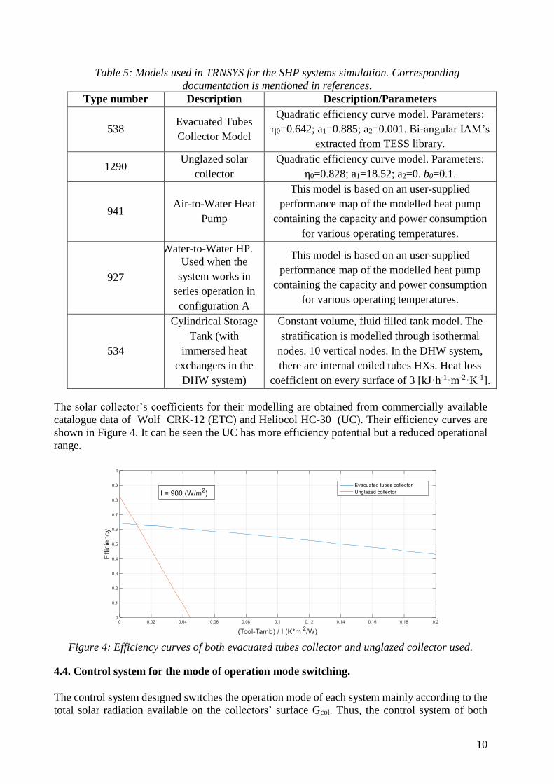
Table 5: Models used in TRNSYS for the SHP systems simulation. Corresponding
documentation is mentioned in references.
Type number Description Description/Parameters
538 Evacuated Tubes
Collector Model
Quadratic efficiency curve model. Parameters:
η0=0.642; a1=0.885; a2=0.001. Bi-angular IAM’s
extracted from TESS library.
1290 Unglazed solar
collector
Quadratic efficiency curve model. Parameters:
η0=0.828; a1=18.52; a2=0. b0=0.1.
941 Air-to-Water Heat
Pump
This model is based on an user-supplied
performance map of the modelled heat pump
containing the capacity and power consumption
for various operating temperatures.
927
Water-to-Water HP.
Used when the
system works in
series operation in
configuration A
This model is based on an user-supplied
performance map of the modelled heat pump
containing the capacity and power consumption
for various operating temperatures.
534
Cylindrical Storage
Tank (with
immersed heat
exchangers in the
DHW system)
Constant volume, fluid filled tank model. The
stratification is modelled through isothermal
nodes. 10 vertical nodes. In the DHW system,
there are internal coiled tubes HXs. Heat loss
coefficient on every surface of 3 [kJ·h-1·m-2·K-1].
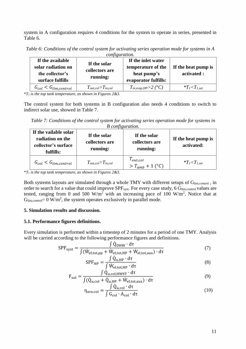
The solar collector’s coefficients for their modelling are obtained from commercially available
catalogue data of Wolf CRK-12 (ETC) and Heliocol HC-30 (UC). Their efficiency curves are
shown in Figure 4. It can be seen the UC has more efficiency potential but a reduced operational
range.
Figure 4: Efficiency curves of both evacuated tubes collector and unglazed collector used.
4.4. Control system for the mode of operation mode switching.
The control system designed switches the operation mode of each system mainly according to the
total solar radiation available on the collectors’ surface Gcol. Thus, the control system of both
11
system in A configuration requires 4 conditions for the system to operate in series, presented in
Table 6.
Table 6: Conditions of the control system for activating series operation mode for systems in A
configuration.
If the available
solar radiation on
the collector’s
surface fulfills
If the solar
collectors are
running:
If the inlet water
temperature of the
heat pump’s
evaporator fulfills:
If the heat pump is
activated :
𝐺𝑐𝑜𝑙 < 𝐺𝑙𝑖𝑚,𝑐𝑜𝑛𝑡𝑟𝑜𝑙 Tout,col>Tin,col Tin,evap,HP>2 (°C) *T1<T1,set
*T1 is the top tank temperature, as shown in Figures 2&3.
The control system for both systems in B configuration also needs 4 conditions to switch to
indirect solar use, showed in Table 7.
Table 7: Conditions of the control system for activating series operation mode for systems in
B configuration.
If the vailable solar
radiation on the
collector’s surface
fulfills:
If the solar
collectors are
running:
If the solar
collectors are
running:
If the heat pump is
activated:
𝐺𝑐𝑜𝑙 < 𝐺𝑙𝑖𝑚,𝑐𝑜𝑛𝑡𝑟𝑜𝑙 Tout,col>Tin,col 𝑇𝑜𝑢𝑡,𝑐𝑜𝑙
> 𝑇𝑎𝑚𝑏 + 1 (°𝐶) *T1<T1,set
*T1 is the top tank temperature, as shown in Figures 2&3.
Both systems layouts are simulated through a whole TMY with different setups of Glim,control , in
order to search for a value that could improve SPFsyst. For every case study, 6 Glim,control values are
tested, ranging from 0 and 500 W/m2 with an increasing pace of 100 W/m2. Notice that at
Glim,control= 0 W/m2, the system operates exclusively in parallel mode.
5. Simulation results and discussion.
5.1. Performance figures definitions.
Every simulation is performed within a timestep of 2 minutes for a period of one TMY. Analysis
will be carried according to the following performance figures and definitions.
SPFsyst =∫ QDHW ∙ dτ
∫(Wel,tot,pp + Wel,tot,HP + Wel,tot,aux) ∙ dτ
(7)
SPFHP =∫ Qu,HP ∙ dτ
∫ Wel,tot,HP ∙ dτ
(8)
Fsol =∫ Qu,col,HWST ∙ dτ
∫(Qu,col + Qu,HP + Wel,tot,aux) ∙ dτ
(9)
ηave,col =∫ Qu,col ∙ dτ
∫ Gcol ∙ Acol ∙ dτ
((10)
12
Notice Fsol consider solar heat when in direct use and ηave,col in both parallel and series operation.
Also, the free energy fraction, defined as the renewable energy heat fraction delivered to the
HWST can be calculated as in equation (11).
Ffree =∫ Qfree ∙ dτ
∫(Qu,HP + Qu,col,HWST + Wel,tot,aux) ∙ dτ=
∫ Qfree ∙ dτ (11)
∫ Qfree ∙ dτ = ∫(Qu,col + QairHP) ∙ dτ = ∫(Qu,col,HWST + QHP,evaps) ∙ dτ
= ∫(Qu,col,HWST + Qu,HP − Wel,tot,HP)
(12)
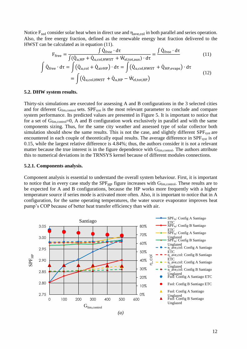
5.2. DHW system results.
Thirty-six simulations are executed for assessing A and B configurations in the 3 selected cities
and for diferent Glim,control sets. SPFsyst is the most relevant parameter to conclude and compare
system performance. Its predicted values are presented in Figure 5. It is important to notice that
for a set of Glim,control=0, A and B configuration work exclusively in parallel and with the same
components sizing. Thus, for the same city weather and assessed type of solar collector both
simulation should show the same results. This is not the case, and slightly different SPFsyst are
encountered in each couple of theoretically equal results. The average difference in SPFsyst is of
0.15, while the largest relative difference is 4.84%; thus, the authors consider it is not a relevant
matter because the true interest is in the figure dependence with Glim,control. The authors attribute
this to numerical deviations in the TRNSYS kernel because of different modules connections.
5.2.1. Components analysis.
Component analysis is essential to understand the overall system behaviour. First, it is important
to notice that in every case study the SPFHP figure increases with Glim,control. These results are to
be expected for A and B configurations, because the HP works more frequently with a higher
temperature source if series mode is activated more often. Also, it is important to notice that in A
configuration, for the same operating temperatures, the water source evaporator improves heat
pump’s COP because of better heat transfer efficiency than with air.
(a)
0%
10%
20%
30%
40%
50%
60%
70%
80%
2.75
2.80
2.85
2.90
2.95
3.00
3.05
0 100 200 300 400 500 600
η_c
ol
SP
FH
P
Glim,control
SantiagoSPFₕₚ: Config A Santiago
ETCSPFₕₚ: Config B Santiago
ETCSPFₕₚ: Config A Santiago
UnglazedSPFₕₚ: Config B Santiago
Unglazedη_ave,col: Config A Santiago
ETCη_ave,col: Config B Santiago
ETCη_ave,col: Config A Santiago
Unglazedη_ave,col: Config B Santiago
UnglazedFsol: Config A Santiago ETC
Fsol: Config B Santiago ETC
Fsol: Config A Santiago
UnglazedFsol: Config B Santiago
Unglazed
13
(b)
(c)
Figure 5: 𝑆𝑃𝐹𝐻𝑃 , Fsol and ηave,coll for each case study in the climates of (a) Santiago, (b)
Concepción and (c) Puerto Montt in the DHW system.
A comparative analysis between SPFHP tendencies show that A configuration has the better
relative increase of this figure, reaching a 6.6% rise for Santiago’s climate using ETCs. On its
side, B configuration only manages to improve SPFHP in 3.5% for the same climate and SCs. For
each scenario, as expected, the double source HP appears as the best option to improve the
component’s performance, as shown in Table 8.
0%
10%
20%
30%
40%
50%
60%
70%
2.84
2.86
2.88
2.90
2.92
2.94
2.96
2.98
3.00
3.02
0 100 200 300 400 500 600
SP
FH
P
Glim,control
Concepción SPFₕₚ: Config A Concepción
ETCSPFₕₚ: Config B Concepción
ETCSPFₕₚ: Config A Concepción
UnglazedSPFₕₚ: Config B Concepción
Unglazedη_ave,col: Config A
Concepción ETCη_ave,col: Config B
Concepción ETCη_ave,col: Config A
Concepción Unglazedη_ave,col: Config B
Concepción UnglazedFsol: Config A Concepción
ETCFsol: Config B Concepción
ETCFsol: Config A Concepción
UnglazedFsol: Config B Concepción
Unglazed
15%
25%
35%
45%
55%
65%
75%
2.84
2.86
2.88
2.90
2.92
2.94
2.96
2.98
3.00
3.02
0 100 200 300 400 500 600
η_c
ol
SP
FH
P
Glim,control
Pto. MonttSPFₕₚ: Config A Pto. Montt
ETCSPFₕₚ: Config B Pto. Montt
ETCSPFₕₚ: Config A Pto. Montt
UnglazedSPFₕₚ: Config B Pto. Montt
Unglazedη_ave,col: Config A Pto.
Montt ETCη_ave,col: Config B Pto.
Montt ETCη_ave,col: Config A Pto.
Montt Unglazedη_ave,col: Config B Pto.
Montt UnglazedFsol: Config A Pto. Montt
ETCFsol: Config B Pto. Montt
ETCFsol: Config A Pto. Montt
UnglazedFsol: Config B Pto. Montt
Unglazed
14
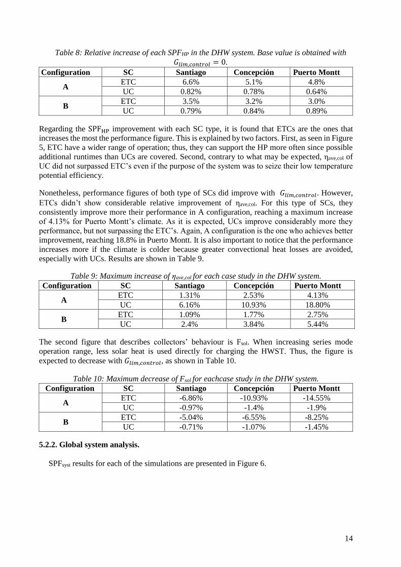
Table 8: Relative increase of each SPFHP in the DHW system. Base value is obtained with
𝐺𝑙𝑖𝑚,𝑐𝑜𝑛𝑡𝑟𝑜𝑙 = 0.
Configuration SC Santiago Concepción Puerto Montt
A ETC 6.6% 5.1% 4.8%
UC 0.82% 0.78% 0.64%
B ETC 3.5% 3.2% 3.0%
UC 0.79% 0.84% 0.89%
Regarding the SPFHP improvement with each SC type, it is found that ETCs are the ones that
increases the most the performance figure. This is explained by two factors. First, as seen in Figure
5, ETC have a wider range of operation; thus, they can support the HP more often since possible
additional runtimes than UCs are covered. Second, contrary to what may be expected, ηave,col of
UC did not surpassed ETC’s even if the purpose of the system was to seize their low temperature
potential efficiency.
Nonetheless, performance figures of both type of SCs did improve with 𝐺𝑙𝑖𝑚,𝑐𝑜𝑛𝑡𝑟𝑜𝑙. However,
ETCs didn’t show considerable relative improvement of ηave,col. For this type of SCs, they
consistently improve more their performance in A configuration, reaching a maximum increase
of 4.13% for Puerto Montt’s climate. As it is expected, UCs improve considerably more they
performance, but not surpassing the ETC’s. Again, A configuration is the one who achieves better
improvement, reaching 18.8% in Puerto Montt. It is also important to notice that the performance
increases more if the climate is colder because greater convectional heat losses are avoided,
especially with UCs. Results are shown in Table 9.
Table 9: Maximum increase of ηave,col for each case study in the DHW system.
Configuration SC Santiago Concepción Puerto Montt
A ETC 1.31% 2.53% 4.13%
UC 6.16% 10.93% 18.80%
B ETC 1.09% 1.77% 2.75%
UC 2.4% 3.84% 5.44%
The second figure that describes collectors’ behaviour is Fsol. When increasing series mode
operation range, less solar heat is used directly for charging the HWST. Thus, the figure is
expected to decrease with 𝐺𝑙𝑖𝑚,𝑐𝑜𝑛𝑡𝑟𝑜𝑙, as shown in Table 10.
Table 10: Maximum decrease of Fsol for eachcase study in the DHW system.
Configuration SC Santiago Concepción Puerto Montt
A ETC -6.86% -10.93% -14.55%
UC -0.97% -1.4% -1.9%
B ETC -5.04% -6.55% -8.25%
UC -0.71% -1.07% -1.45%
5.2.2. Global system analysis.
SPFsyst results for each of the simulations are presented in Figure 6.
15
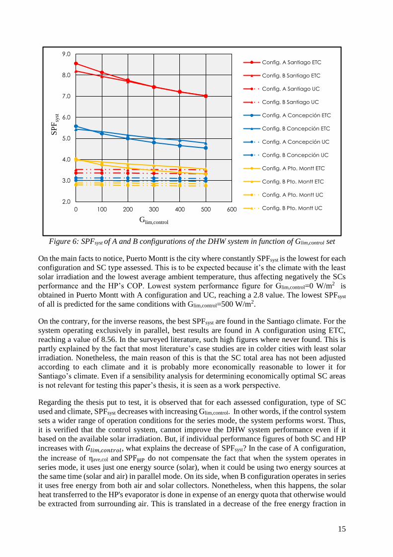
Figure 6: SPFsyst of A and B configurations of the DHW system in function of Glim,control set
On the main facts to notice, Puerto Montt is the city where constantly SPFsyst is the lowest for each
configuration and SC type assessed. This is to be expected because it’s the climate with the least
solar irradiation and the lowest average ambient temperature, thus affecting negatively the SCs
performance and the HP’s COP. Lowest system performance figure for Glim,control=0 W/m2 is
obtained in Puerto Montt with A configuration and UC, reaching a 2.8 value. The lowest SPFsyst
of all is predicted for the same conditions with Glim,control=500 W/m2.
On the contrary, for the inverse reasons, the best SPFsyst are found in the Santiago climate. For the
system operating exclusively in parallel, best results are found in A configuration using ETC,
reaching a value of 8.56. In the surveyed literature, such high figures where never found. This is
partly explained by the fact that most literature’s case studies are in colder cities with least solar
irradiation. Nonetheless, the main reason of this is that the SC total area has not been adjusted
according to each climate and it is probably more economically reasonable to lower it for
Santiago’s climate. Even if a sensibility analysis for determining economically optimal SC areas
is not relevant for testing this paper’s thesis, it is seen as a work perspective.
Regarding the thesis put to test, it is observed that for each assessed configuration, type of SC
used and climate, SPFsyst decreases with increasing Glim,control. In other words, if the control system
sets a wider range of operation conditions for the series mode, the system performs worst. Thus,
it is verified that the control system, cannot improve the DHW system performance even if it
based on the available solar irradiation. But, if individual performance figures of both SC and HP
increases with 𝐺𝑙𝑖𝑚,𝑐𝑜𝑛𝑡𝑟𝑜𝑙, what explains the decrease of SPFsyst? In the case of A configuration,
the increase of ηave,col and SPFHP do not compensate the fact that when the system operates in
series mode, it uses just one energy source (solar), when it could be using two energy sources at
the same time (solar and air) in parallel mode. On its side, when B configuration operates in series
it uses free energy from both air and solar collectors. Nonetheless, when this happens, the solar
heat transferred to the HP's evaporator is done in expense of an energy quota that otherwise would
be extracted from surrounding air. This is translated in a decrease of the free energy fraction in
2.0
3.0
4.0
5.0
6.0
7.0
8.0
9.0
0 100 200 300 400 500 600
SP
Fsy
st
Glim,control
Config. A Santiago ETC
Config. B Santiago ETC
Config. A Santiago UC
Config. B Santiago UC
Config. A Concepción ETC
Config. B Concepción ETC
Config. A Concepción UC
Config. B Concepción UC
Config. A Pto. Montt ETC
Config. B Pto. Montt ETC
Config. A Pto. Montt UC
Config. B Pto. Montt UC
16
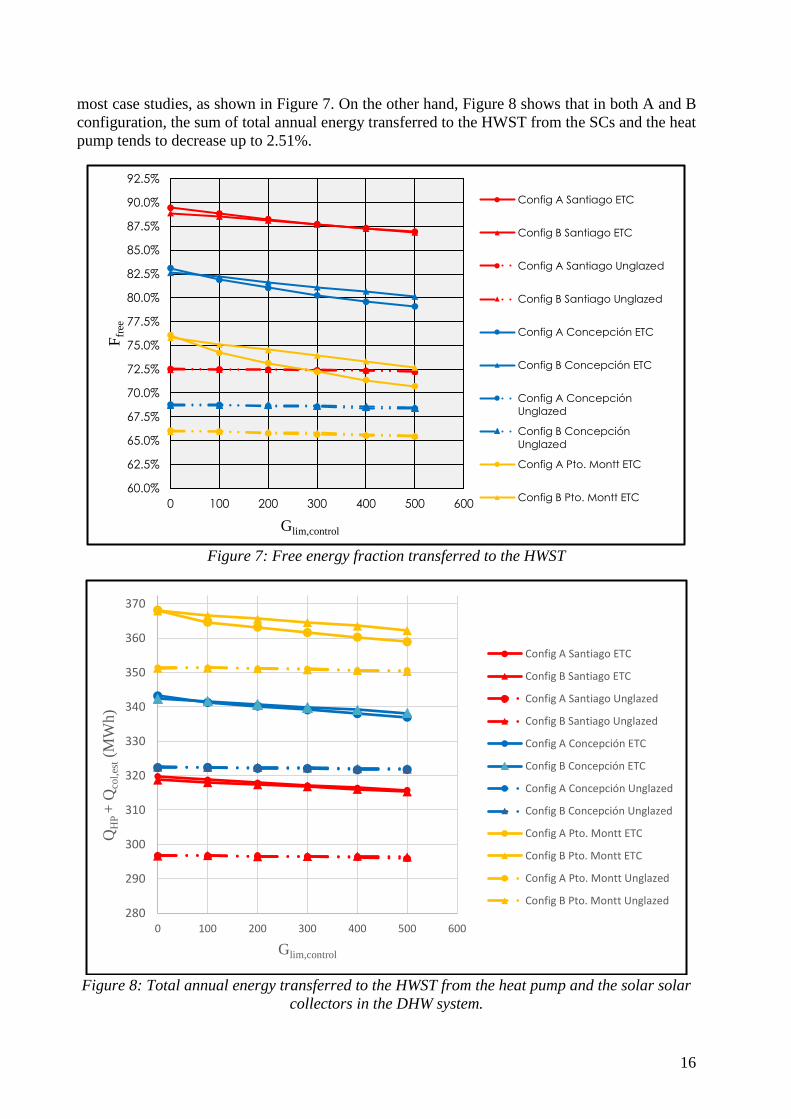
most case studies, as shown in Figure 7. On the other hand, Figure 8 shows that in both A and B
configuration, the sum of total annual energy transferred to the HWST from the SCs and the heat
pump tends to decrease up to 2.51%.
Figure 7: Free energy fraction transferred to the HWST
Figure 8: Total annual energy transferred to the HWST from the heat pump and the solar solar
collectors in the DHW system.
60.0%
62.5%
65.0%
67.5%
70.0%
72.5%
75.0%
77.5%
80.0%
82.5%
85.0%
87.5%
90.0%
92.5%
0 100 200 300 400 500 600
Ffr
ee
Glim,control
Config A Santiago ETC
Config B Santiago ETC
Config A Santiago Unglazed
Config B Santiago Unglazed
Config A Concepción ETC
Config B Concepción ETC
Config A Concepción
Unglazed
Config B Concepción
Unglazed
Config A Pto. Montt ETC
Config B Pto. Montt ETC
280
290
300
310
320
330
340
350
360
370
0 100 200 300 400 500 600
QH
P +
Qco
l,es
t(M
Wh)
Glim,control
Config A Santiago ETC
Config B Santiago ETC
Config A Santiago Unglazed
Config B Santiago Unglazed
Config A Concepción ETC
Config B Concepción ETC
Config A Concepción Unglazed
Config B Concepción Unglazed
Config A Pto. Montt ETC
Config B Pto. Montt ETC
Config A Pto. Montt Unglazed
Config B Pto. Montt Unglazed
17
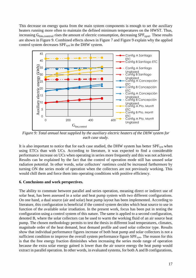
This decrease on energy quota from the main system components is enough to set the auxiliary
heaters running more often to maintain the defined minimum temperatures on the HWST. Thus,
increasing Glim,control rises the amount of electric consumption, decreasing SPFsyst. These results
are shown in Figure 9. Combined effects shown in Figure 7 and Figure 9 explain why the applied
control system decreases SPFsyst in the DHW system.
Figure 9: Total annual heat supplied by the auxiliary electric heaters of the DHW system for
each case study.
It is also important to notice that for each case studied, the DHW system has better SPFsyst when
using ETCs than with UCs. According to literature, it was expected to find a considerable
performance increase on UCs when operating in series more frequently and this was not achieved.
Results can be explained by the fact that the control of operation mode still has unused solar
radiation potential. In other words, solar collectors’ runtimes could be increased furthermore by
turning ON the series mode of operation when the collectors are not previously working. This
would chill them and force them into operating conditions with positive efficiency.
6. Conclusions and work perspectives.
The ability to commute between parallel and series operation, meaning direct or indirect use of
solar heat, has been assessed in a solar and heat pump system with two different configurations.
On one hand, a dual source (air and solar) heat pump layout has been implemented. According to
literature, this configuration is beneficial if the control system decides which heat source to use in
function of the available solar irradiation. In the present work, focus has been put in testing the
configuration using a control system of this nature. The same is applied to a second configuration,
denoted B, where the solar collectors can be used to warm the working fluid of an air source heat
pump. The chosen methodology permits to test the thesis in different load temperatures, climates,
magnitude order of the heat demand, heat demand profile and used solar collector type. Results
show that individual performance figures increase of both heat pump and solar collectors is not a
sufficient condition to improve the overall system performance figure SPFsyst. The reason for this
is that the free energy fraction diminishes when increasing the series mode range of operation
because the extra solar energy gained is lower than the air source energy the heat pump would
extract in parallel operation. In other words, in evaluated systems, for both A and B configurations,
0
5
10
15
20
25
30
35
40
45
0 200 400 600
Aux
ilia
ry e
lect
ric
ener
gy (
kW
h)
Glim,control
Config A Santiago
ETCConfig B Santiago ETC
Config A Santiago
UnglazedConfig B Santiago
UnglazedConfig A Concepción
ETCConfig B Concepción
ETCConfig A Concepción
UnglazedConfig B Concepción
UnglazedConfig A Pto. Montt
ETCConfig B Pto. Montt
ETCConfig A Pto. Montt
Unglazed

18
there is not a limit solar irradiation below which series operation is beneficial. In fact, SPFsyst tends
to decrease in most case studies.
Special discussion is done regarding the fact that there is still unused solar irradiation available
than the series mode of operation could seize. Thus, the most important work perspective that
arise in this work is the execution of numerical simulations of the same system layouts, in the
same climates, using a control system that switches the mode of operation allowing the SCs to
achieve all their potential runtimes. This would be done by forcing them to lower their temperature
by chilling them with the HP when they were not previously working. Then, the SCs would be
driven to reach a temperature where they meet a positive efficiency. Care should be taken to not
allow this when there is no available solar energy, as in that condition the heat pump would
perform better just taking heat from the air. A secondary work perspective is the economical and
sensitivity analysis of the sizing of every main component implemented in the modelling. SHP
systems are sensible to climate conditions and heat loads; thus, having additional information of
the performance of these systems whose implementation is on the arise in Chile would be of
interest.
Acknowledgements
This study was funded by the Chilean research agency CONICYT through the research project
FONDECYT 1150965.
NOMENCLATURE
SHP Solar and heat pump
DHW Domestic hot water
COP Coefficient of performance
F Fraction
HP Heat pump
SC Solar collector
SPF Seasonal performance factor
IEA International energy agency
SHC Solar heating and cooling
SH Space heating
HWST Hot water storage tank
ASHRAE American society of heating,
refrigerating and air-conditioning engineers
ASPE American society of plumbing
engineers
ETC Evacuated tubes collector
UC Unglazed collector
IAM Incidence angle modifier
HX Heat exchanger
TMY Typical meteorological year
G Solar radiation, W·m-2
�� Flow rate, kg·s-1
𝜌 Density, kg·m-3
�� Volumetric flow rate, m3·s-1
�� Power, W
h Enthalpy
𝑟 Ratio
𝐾, 𝑅, 𝑎 Constant coefficient
Subscripts
lim Limit
control Control system
syst System
ref Refrigerant
swept Swept
vol Volumetric
el Electric
comp Compressor
out Outlet
in Inlet
s Isentropic
p Pressure
i inth therm
log Logarithmic
HX Heat exchanger
col Collector, collectors
evap Evaporator
HP Heat pump
Set Set on the control system
amb Ambient
u Useful
tot Total
aux Auxiliary
sol Solar
DHW Domestic hot water
ave Average
free Free renewable energy

19
U Global heat transference coefficient,
W·K-1·m-2
A Area, m2
�� Heat flow, W·s-1
T Temperature, K
Greek symbols
∆ Delta, difference
𝜂 Efficiency
𝛼 Constant coefficient
τ Time, s
REFERENCES
Vega J., Cuevas C. Simulation study of a combined solar and heat pump system for heating and domestic hot water
in a medium rise residential building at Concepción in Chile. Applied Thermal Engineering 2018; 141:565-578.
Ruschenburg J, Herkel S, Henning H. A statistical analysis on market-available solar thermal heat pump systems.
Solar Energy 2013; 95:79-89.
Carbonell D., Philippen D., Granzotto M., Haller M.Y. Simulation of a solar-ice system for heatin applications.
System validation with one-year of monitoring data. Energy and Buildings 126 (2016) 846-858.
Hadorn J. Solar and heat pump systems for residential buildings. First edition. Berlin: Ernst & Sohn GmbH & Co;
2015.
Fraga C., Hollmuller P., Mermoud F., Lachal B. Solar assisted heat pump system for multifamily buildings: Towards
a seasonal performance factor of 5? Numerical sensitivity analysis based on a monitored case study. Solar Energy
146 (2017) 543-564.
Sun X., Dai Y., Novakovic V., Wu J., Wang R. Performance comparison of direct expansion solar-assisted heat pump
and conventional air source heat pump for domestic hot water. Energy Procedia 70 (2015) 394-401.
Sterling S.J., Collins M.R. Feasibility analysis of an indirect heat pump assisted solar domestic hot water system.
Applied Energy 93 (2012) 11-17.
Liu H., Jiang Y., Yao Y. The field test and optimization of a solar assisted heat pump system for space heating in
extremely cold area. Sustainable Cities and Society 13 (2014) 97-104.
Poppi S, Bales C, Heinz A, Hengel F, Chèze D, Mojic I, Cialani C. Analysis of system improvements in solar thermal
and air source heat pump combisystems. Applied Energy 2016; 173:606-623.
Tzivanidis C, Bellos E, Mitsopoulos G, Antonopoulos K, Delis A. Energetic and financial evaluation of a solar
assisted heat pump heating system with other usual heating systems in Athens. Applied Thermal Engineering 2016;
106:87-97.
Kamil Kaygusuz. Performance of Solar-Assisted Heat-Pump Systems. Applied Energy (1995) 93-109.
Lerch W., Heinz A., Heimrath R. Direct use of solar energy as heat source for a heat pump in comparison to a
conventional parallel solar air heat pump system. Energy and Buildings 100 (2015) 34-42.
Renato M. Lazarrin. Dual source heat pump systems: Operation and performance. Energy and Buildings 52 (2012)
77-85.
Haller M, Frank E. On the potential of using heat from solar thermal collectors for heat pump evaporators. ISES Solar
World Congress, 28. August-2 September 2011, Kassel, Germany.
Heinz A., Haller M. Model of Sub-components and Validation for the IEA SHC Tas 44/HPP Annex 38; A3
Description of TRNSYS Type 877 by IWT and SPF. Solar Heating & Cooling Programme (SHC), International
Energy Agency (IEA).

20
Banister C, Collins M. Development and performance of a dual tank solar-assisted heat pump system. Applied Energy
2015; 149: 125-132.
He W, Hong X, Zhao X, Zhang X, Shen J, Ji J. Operational performance of a novel heat pump assisted solar façade
loop-heat-pipe water heating system. Applied Energy 2015; 146: 371-382.
Meteotest, Meteonorm Version 7, Bern, Switzerland, http://www.meteonorm.com/, 2015.
ASHRAE Standard 90.2, Energy efficient design of low-rise residential buildings. American Society of Heating,
Refrigerating and Air Conditioning Engineers, Atlanta, USA, 2007.
Domestic Water Heating Design Manual, American Society of Plumbing Engineers (ASPE), 2003.
TRNSYS 17 Mathematical Reference, TRNSYS 17 Documentation, Madison, Wisconsin, USA.
Thermal Energy Systems Specialists, Solar Library Mathematical Reference, Component Libraries for the TRNSYS
Simulation Environment, Madison, Wisconsin, USA, Madison, Wisconsin, USA, 2012.
Thermal Energy Systems Specialists, HVAC Library Mathematical Reference, Component Libraries for the TRNSYS
Simulation Environment, Madison, Wisconsin, USA, 2012.
Thermal Energy Systems Specialists, Storage Tank Library Mathematical Reference, Component Libraries for the
TRNSYS Simulation Environment, Madison, Wisconsin, USA, 2012.


![Intro to parallel and series/parallel HEV architectures ...ecee.colorado.edu/~ecen5017/lectures/CU/L12_slides.pdf · Intro to parallel and series/parallel HEV ... time [sec] Step](https://img.pdfslide.us/doc/110x75/5ffdaa80f8451c652b521e2e/intro-to-parallel-and-seriesparallel-hev-architectures-ecee-ecen5017lecturescul12slidespdf.jpg)