Embed Size (px)
Citation preview

OWNER’S MANUAL
Includes Installation Instructions
SOLAR WATER HEATERS
Solahart Industries Pty Ltd ABN 45 064 945 848

CONTENTS
Here's How It Works ................................................................................................................. 1
Facts You Should Know About Your Solahart Water Heater .................................................. 2
Operating Your Solar Water Heater ......................................................................................... 4
Maintenance ............................................................................................................................. 8
Installation Instructions - All Models ....................................................................................... 10
Installation Instructions – Closed Circuit Series...................................................................... 18
Installation Instructions – Open Circuit Series ........................................................................ 24
Technical Specifications ......................................................................................................... 28
Annual Performance Calculations For Europe .................................................................................30
South African System SANS 1307 Details .......................................................................................35
Installation Diagram Models 151J & 151KF .....................................................................................36
Installation Diagram Models 151L & 151L Free Heat ......................................................................37
Installation Diagram Models 181J, 181KF, 181BTC, 181J Free Heat, 181KF Free Heat & 181BTC Free Heat ...........................................................................................................................38
Installation Diagram Models 181L & 181L Free Heat ......................................................................39
Installation Diagram Models 182J, 182KF, 182J Free Heat & 182KF Free Heat .............................40
Installation Diagram Models 221J & 221KF .....................................................................................41
Installation Diagram Models 301J & 301KF .....................................................................................42
Installation Diagram Models 301L & 301L Free Heat ......................................................................43
Installation Diagram Models 302J, 302KF, 302BTC, 302J Free Heat, 302KF Free Heat & 302BTC Free Heat ...........................................................................................................................44
Installation Diagram Models 302L & 302L Free Heat ......................................................................45
Installation Diagram Models 303J, 303KF, 303J Free Heat & 303KF Free Heat .............................46
Installation Diagram Models 303L & 303L Free Heat ......................................................................47
Installation Diagram Models 443J, 443KF, 443BTC, 443J Free Heat, 443KF Free Heat & 443BTC Free Heat ...........................................................................................................................48
Installation Diagram Models 443L & 443L Free Heat ......................................................................49
Connection Details .................................................................................................................. 50
Installer’s Checklist ................................................................................................................. 54
Servicing ................................................................................................................................. 54
Solahart Thermosiphon Solar Water Heater Warranty .......................................................... 55
HOME OWNER: WE RECOMMEND THAT YOU READ PAGES 1 TO 9 The other pages are intended for the installer but may be of interest to you
33-1197 Revision H – 2013 November

33-1197 Solahart Owner‟s Manual – Thermosiphon Systems - Revision H – Nov 2013 1
HERE'S HOW IT WORKS
Solahart thermosiphon solar water heaters are available in two series:
Closed Circuit Series – J, KF, LCSC & BTC models
Open Circuit Series – L & LCSD models
Both series transfer heat absorbed from the sun by the solar collectors to the water storage tank through the Natural
Thermosiphon Principle without the need for pumps or sensors.
The Solahart collectors absorb solar energy. The low-iron content solar glass allows more solar energy to pass through and
be retained than conventional glass.
In the Closed Circuit Series, heat is absorbed by the collector and
passed to the „Hartgard‟ heat transfer liquid inside the collector. As the
temperature of the „Hartgard‟ increases, the hot fluid rises up through
the collector by the Natural Thermosiphon Principle, into the heat
exchanger jacket around the potable water storage tank. Here, the heat
is transferred to the potable water, cooling the „Hartgard‟ fluid.
The cooler fluid is then forced back down into the collectors through
the displacement action of further hot fluid rising up into the heat
exchanger jacket.
Diagram of Closed Circuit Series
The cooler fluid that has been forced down is again heated
in the collectors and rises back up to pass the heat to the
potable water in the storage tank. This circulation repeats
until all water in the storage tank is heated.
Open Circuit Series Closed Circuit Series
For the Open Circuit Series, heat is collected directly by the potable
water circulating through the collector. As the potable water heats up, it
rises by the Natural Thermosiphon Principle, directly to the storage
tank. As the heated potable water travels through to the storage tank,
the cooler potable water returns to the collectors. This circulation
repeats until all water in the storage tank is heated.
Diagram of Open Circuit Series

2 33-1197 Solahart Owner‟s Manual – Thermosiphon Systems - Revision H – Nov 2013
FACTS YOU SHOULD KNOW ABOUT YOUR
SOLAHART WATER HEATER
WARNING: FOR CONTINUED SAFETY OF THIS APPLIANCE IT MUST BE INSTALLED, OPERATED AND
MAINTAINED IN ACCORDANCE WITH THE MANUFACTURER‟S INSTRUCTIONS.
CAUTION: THIS WATER HEATER IS ONLY INTENDED TO BE OPERATED BY PERSONS WHO
HAVE THE EXPERIENCE OR THE KNOWLEDGE AND THE CAPABILITIES TO DO SO.
THIS WATER HEATER IS NOT INTENDED TO BE OPERATED BY PERSONS WITH REDUCED
PHYSICAL, SENSORY OR MENTAL CAPABILITIES I.E. THE INFIRM AND CHILDREN.
CHILDREN SHOULD BE SUPERVISED TO ENSURE THEY DO NOT INTERFERE WITH THE
WATER HEATER.
WARNING: THIS WATER HEATER USES 240 V AC POWER FOR THE ELECTRICALLY
OPERATED COMPONENTS. THE REMOVAL OF THE FRONT COVER WILL EXPOSE 240 V
WIRING. IT MUST ONLY BE REMOVED BY A QUALIFIED ELECTRICAL SERVICE PERSON.
CAUTION: CARE SHOULD BE TAKEN NOT TO TOUCH THE PIPE WORK CONNECTING THE
SOLAR STORAGE TANK AND THE SOLAR COLLECTORS. VERY HIGH TEMPERATURE HOT
WATER CAN BE GENERATED BY THE SOLAR COLLECTORS UNDER CERTAIN CONDITIONS
AND WILL FLOW THROUGH THE PIPE WORK FROM THE SOLAR COLLECTORS TO THE SOLAR
STORAGE TANK.
Water Heater Application
This water heater is designed for the purpose of heating potable water. Its use in an application other than this may shorten
its life.
Under normal family use and summer solar conditions, the solar water heater should operate between 60ºC and 70ºC.
However, the temperature can exceed this and under certain circumstances may be as high as 95ºC (see recommendation
below). This can occur during periods of higher solar radiation (particularly in summer) or during long periods of reduced
water usage. Extreme care should be taken in these circumstances.
CAUTION: CHECK THE WATER TEMPERATURE BEFORE USE, SUCH AS WHEN ENTERING A
SHOWER OR FILLING A BATH OR BASIN, TO ENSURE IT IS SUITABLE FOR THE APPLICATION
AND WILL NOT CAUSE SCALD INJURY.
We recommend, and it may also be required by regulations, that an approved temperature limiting device be fitted into the
hot water pipe work to the bathroom and ensuite when this water heater is installed. This will keep the water temperature
below 50 C at the bathroom and ensuite. The risk of scald injury will be reduced and still allow hotter water to the kitchen
and laundry.
Precautions
The water heater must be maintained in accordance with the Owner‟s Manual. Refer to “Maintenance” on page 8 and to
“Anode Inspection and Replacement” on page 8.
If this water heater is to be used where an uninterrupted hot water supply is necessary for your application or business you
should ensure that you have back up redundancy within the hot water system design. This should ensure the continuity of
hot water supply in the event that this water heater were to become inoperable for any reason. We recommend you seek
advice from your plumber or specifier about your needs and building back up redundancy into your hot water supply
system.
Victorian Customers
Notice to Victorian Customers from the Victorian Plumbing Industry Commission. This water heater must be installed by a
licensed person as required by the Victorian Building Act 1993. Only a licensed person will give you a Compliance
Certificate, showing that the work complies with all the relevant Standards. Only a licensed person will have insurance
protecting their workmanship for 6 years. Make sure you use a licensed person to install this water heater and ask for your
Compliance Certificate.
!
!

33-1197 Solahart Owner‟s Manual – Thermosiphon Systems - Revision H – Nov 2013 3
Water Quality - Is It Suitable For The Solahart Water Heater?
Your Solahart water heater is suitable for use with water with a total dissolved solid content less than 1,000 ppm and for
which the total hardness does not exceed 200 ppm CaCO3. Water supplies having calcium hardness (CaCO3) and an
alkalinity in excess of 150 ppm should be treated by a softening process prior to use with this water heater to prevent
scaling and damage to the electric booster element.
A water analysis can be obtained from your water supply authority.
Period Of Reduced Usage Or Holidays
WARNING: IF THE WATER HEATER IS LEFT UNUSED FOR TWO WEEKS OR MORE,
FLAMMABLE HYDROGEN GAS MAY ACCUMULATE IN THE WATER CYLINDER.
To dissipate this gas safely, it is recommended that a sink hot tap be turned on for several minutes. Do not use a
dishwasher, clothes washer or other appliance for this purpose. During this procedure there must be no smoking, open
flames or any electrical appliance operating nearby. If hydrogen is discharged through the tap it will make an unusual sound
like air escaping.
‘Hartgard’ Solution – Freeze Protection
Solahart Closed Circuit Systems are protected against freezing or harsh water conditions by our exclusive „Hartgard‟ fluid.
„Hartgard‟ is a blue, non-toxic, propylene glycol fluid which, when mixed with water, provides the Heat Transfer Fluid
contained in the solar collectors and the heat exchanger jacket around the tank. „Hartgard‟ is used to lower the freezing
temperature of the Heat Transfer Fluid and so provides protection against freezing (Note: for the correct % of Hartgard in
the Heat Transfer Fluid, refer to the section on Frost / Freeze Protection). „Hartgard‟ is a special food grade solution and is
the only solution permitted to be used in the closed circuit systems. Hartgard has been approved by the National Health and
Medical Research Council of Australia.
WARNING: SHOULD THE WATER FROM YOUR CLOSED CIRCUIT SERIES WATER HEATER
APPEAR BLUE, THEN THIS MAY INDICATE A LEAK OF „HARTGARD‟ FROM THE HEAT
EXCHANGE JACKET INTO THE POTABLE WATER.
Although ‘Hartgard‟ is of food-grade quality and not hazardous to health, the blue colour in the water does indicate a fault
and your Solahart dealer should be contacted to inspect the system.
Over-Temperature Protection System
The Closed Circuit Series solar water heaters have a means of controlling the maximum temperature of the water in the
storage tank. These systems may be installed with a „HartStat‟ valve located between the hot outlet of the collectors and the
inlet to the tank heat exchanger. This valve closes when the tank has reached a sufficiently high temperature, thereby
preventing further heat transfer to the tank, and thus limiting its temperature.
The Open Circuit Series systems may be installed with a „TRV‟ located between the cold inlet of the tank and the cold inlet
of the collectors. This valve restricts the flow through the collectors when the tank has reached a sufficiently high
temperature.
PR6 / PR200 Jacket Pressure Relief Valve
The Closed Circuit Series tank‟s heat exchange jacket has a pressure relief valve located in the vent pipe of the jacket. This
relief valve is to prevent over-pressurisation of the closed circuit either due to incorrect filling or abnormal operating
conditions. During the water heater's first summer season, fluid will discharge from the relief valve until the ideal closed
circuit fluid volume is established. Discharges from the valve after this time could indicate the water heater is not operating
efficiently. Under these circumstances contact your nearest Solahart dealer immediately. Do not attempt to service the water
heater yourself.
When operating in daylight, the heat exchange circuit will be pressurised and will contain a mixture of superheated water
and steam. Do not remove the PR6 / PR200 valve during operation as there may be a very high SCALDING risk present.
!
!

4 33-1197 Solahart Owner‟s Manual – Thermosiphon Systems - Revision H – Nov 2013
OPERATING YOUR SOLAR WATER HEATER
Primary heating of your hot water will be from solar energy. The solar heating requires no operation by the user.
Supplementary water heating (“boosting”) is also provided. Dependent upon the system that you have purchased, this will
be either:
In-tank electric boosting
In-series gas boosting
Note: Australian Standard AS 3498 requires that a water heater provides the means to inhibit the growth of Legionella
bacteria in potable water.
With in-tank boosting, this water heater can satisfy this AS 3498 requirement provided the booster is either
permanently on or switched on by timer control for a sufficient period each day, and the electric booster thermostat
setting is 60°C or higher. Refer to the tables commencing on page 5 for recommended boosting periods.
If this water heater is installed with an in-series continuous flow gas booster, then this requirement of AS 3498 can be
satisfied provided the booster is permanently on, its preset outlet temperature setting is 70°C or higher and a remote
temperature controller is not used.
If this water heater is installed with an in-series storage booster, then this requirement of AS 3498 can be satisfied
provided the storage booster is permanently on and its thermostat setting is 60°C or higher.
IN-TANK BOOSTING
An isolating switch is installed in the electrical meter box for an electrically in-tank boosted model. This should be left
switched on to allow the booster heating unit to operate if required. The booster heating unit is for heating the water at
times of low solar energy gain, such as during very cloudy or rainy weather, or during the colder months.
The booster heating unit will only activate if heating is required and power is available from the switchboard. When the
water is below the thermostat setting, the booster heating unit will turn on and heat the water. The booster heating unit will
automatically turn off when the temperature of the water reaches the thermostat setting. If the water temperature drops
below the setting again the booster will re-activate.
The water heater features a tradesperson adjustable thermostat. This requires a licensed tradesperson to make any
temperature adjustments. The thermostat is factory set at 60°C and has a maximum temperature setting of 70°C.
Leaving the isolating switch switched on will also provide a sufficient period of time each day for the booster heating unit
to operate, if required, to satisfy the requirements of AS 3498.
The amount of water heated by the raised booster heating unit of a thermosiphon storage tank is:
150 model 180 model 220 model 300 model 440 model
75 litres 90 litres 110 litres 150 litres 200 litres
The overall performance and energy savings that you will obtain from your Solahart water heater will depend on your hot
water usage pattern and your operation of the in-tank booster. A time clock may be fitted to the system to turn the booster
on when required. This method can increase energy savings.
The following hints are provided to assist you in with your operation of your solar water heater:
1) Solar energy input is greater on sunny days between 10am and 3pm. If possible, schedule your large hot water
demands (e.g. heavy washing or laundry) for as close as possible to the middle of the day.
2) If a timer is installed, boost your tank‟s water after this 10am to 3pm hot period. The sun has made its maximum
contribution by this time, the booster will then raise the water to the desired temperature if the sun has not done so
(in winter for example).
3) Keep trees in the sun's path at a level where the collectors are not shaded at any time during periods of effective
solar radiation.
Off Peak Electricity & Boosting
If your Solahart water heater‟s in-tank electric booster is connected to an „Off Peak‟ (night rate) electrical supply, it is
important to remember that the booster may only operate late at night. On cloudy days the tank may only gain a small
amount of energy during the day. Careful planning will be required to avoid running out of hot water if large quantities are
drawn during the day. In areas where a „Day Rate‟ electrical switch is permitted, the storage tank can be boosted to ensure
hot water is available at the end of the day.
33-1197 Solahart Owner‟s Manual – Thermosiphon Systems - Revision H – Nov 2013 5
Timer Control of the Tank Boosting
A timer control switch can be installed and will help maximise energy savings with an electrically boosted solar water
heater connected to a continuous, time of use or extended Off-Peak (overnight and day) electricity supply.
If used with an extended Off-Peak (overnight and day) electricity supply, the timer switch should:
Be operated by a continuous power supply on its own circuit from the switchboard with the booster heating unit
operated by the Off-Peak power supply.
A double pole isolating switch is required to be installed at the switchboard to simultaneously isolate both circuits.
Or
Be of a type which has an internal rechargeable battery to keep time when the power supply is not available to the
timer
Programming the Timer
Power must be available to the timer control switch before the booster heating unit can be activated.
The timer control switch should be programmed:
to suit the hot water consumption pattern of the household,
with the end of the boost period to coincide with the commencement of the evening hot water usage,
to enable a boosting period of not less than the recommended continuous length of time for boosting, and
for a period when power will be available for the booster heating unit to operate.
It may be necessary to program a second period into the timer, such as prior to the morning hot water usage.
Note: When daylight saving time applies, you may consider resetting the timer accordingly.
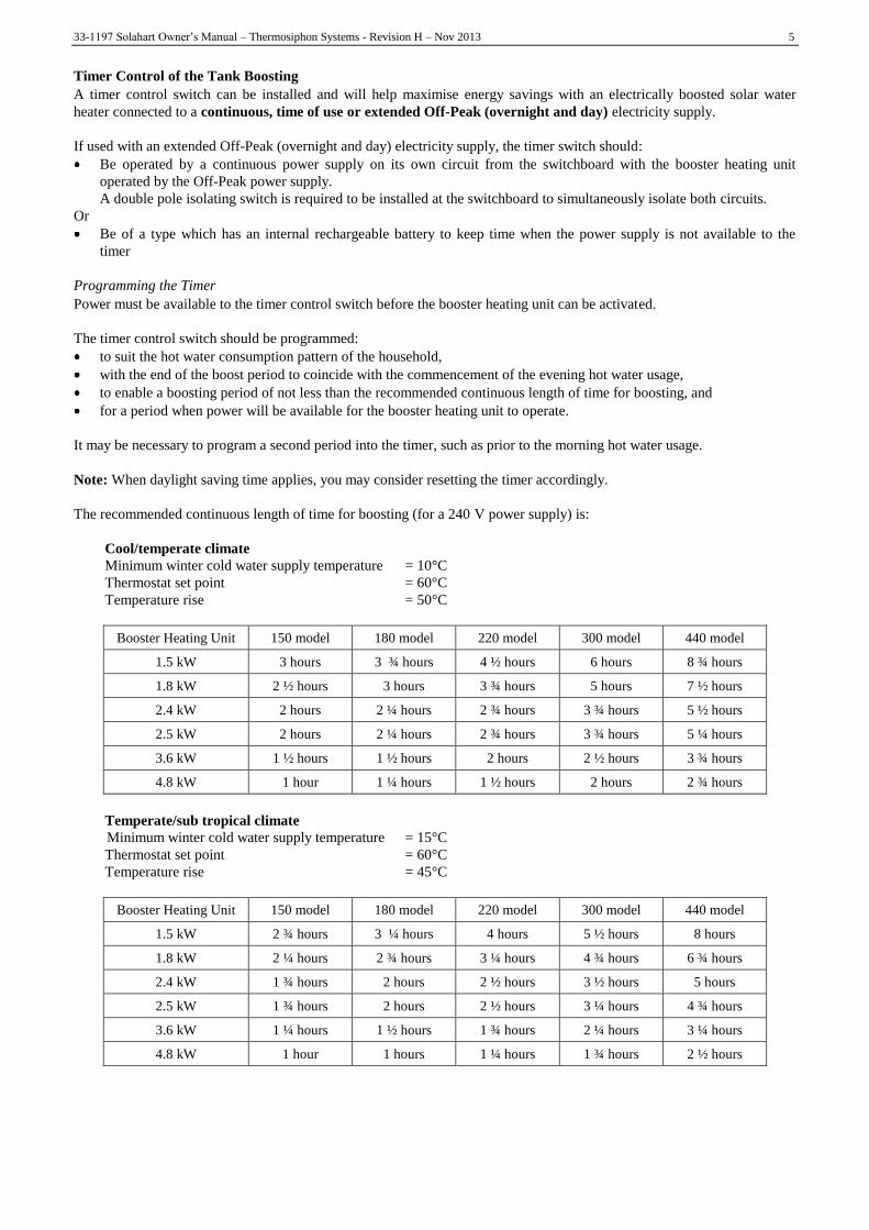
The recommended continuous length of time for boosting (for a 240 V power supply) is:
Cool/temperate climate
Minimum winter cold water supply temperature = 10°C
Thermostat set point = 60°C
Temperature rise = 50°C
Booster Heating Unit 150 model 180 model 220 model 300 model 440 model
1.5 kW 3 hours 3 ¾ hours 4 ½ hours 6 hours 8 ¾ hours
1.8 kW 2 ½ hours 3 hours 3 ¾ hours 5 hours 7 ½ hours
2.4 kW 2 hours 2 ¼ hours 2 ¾ hours 3 ¾ hours 5 ½ hours
2.5 kW 2 hours 2 ¼ hours 2 ¾ hours 3 ¾ hours 5 ¼ hours
3.6 kW 1 ½ hours 1 ½ hours 2 hours 2 ½ hours 3 ¾ hours
4.8 kW 1 hour 1 ¼ hours 1 ½ hours 2 hours 2 ¾ hours
Temperate/sub tropical climate
Minimum winter cold water supply temperature = 15°C
Thermostat set point = 60°C
Temperature rise = 45°C
Booster Heating Unit 150 model 180 model 220 model 300 model 440 model
1.5 kW 2 ¾ hours 3 ¼ hours 4 hours 5 ½ hours 8 hours
1.8 kW 2 ¼ hours 2 ¾ hours 3 ¼ hours 4 ¾ hours 6 ¾ hours
2.4 kW 1 ¾ hours 2 hours 2 ½ hours 3 ½ hours 5 hours
2.5 kW 1 ¾ hours 2 hours 2 ½ hours 3 ¼ hours 4 ¾ hours
3.6 kW 1 ¼ hours 1 ½ hours 1 ¾ hours 2 ¼ hours 3 ¼ hours
4.8 kW 1 hour 1 hours 1 ¼ hours 1 ¾ hours 2 ½ hours

6 33-1197 Solahart Owner‟s Manual – Thermosiphon Systems - Revision H – Nov 2013
Sub tropical / Tropical climate
Minimum winter cold water supply temperature = 20°C
Thermostat set point = 60°C
Temperature rise = 40°C
Booster Heating Unit 150 model 180 model 220 model 300 model 440 model
1.5 kW 2 ½ hours 3 hours 3 ½ hours 4 ¾ hours 7 hours
1.8 kW 2 hours 2 ½ hours 3 hours 4 hours 6 hours
2.4 kW 1 ½ hours 2 hours 2 ¼ hours 3 hours 4 ½ hours
2.5 kW 1 ½ hours 1 ¾ hours 2 ¼ hours 3 hours 4 ¼ hours
3.6 kW 1 hour 1 ¼ hours 1 ½ hours 2 hours 3 hours
4.8 kW ¾ hour 1 hour 1 ¼ hours 1 ½ hours 2 ¼ hours
The recommended boosting periods are sufficient to allow the booster heating unit to heat up the boost volume of the solar
storage tank to 60°C where the winter cold water temperatures do not fall below those shown. This may be necessary
during periods of very low solar energy gain through the solar collectors, such as during constant rain or extremely cloudy
weather, particularly in winter when the incoming cold water temperature is lower. The period will also provide a sufficient
heat up time for the electric booster to operate, if required, to satisfy the requirements of AS 3498.
The booster heating unit will only activate if heating is required and power is available from the timer. When the water is
below the thermostat setting, the booster heating unit will turn on and heat the water. The booster heating unit will
automatically turn off either when the temperature of the water reaches the thermostat setting or at the end of the timer
period, whichever comes first.
IN-SERIES GAS BOOSTING
An in-series gas booster (also known as an instantaneous gas booster) can be installed between the solar water heater and
the hot outlets in the house. This booster should be permanently active. The booster senses the temperature of the water
passing through it: if the water temperature is above its temperature setting it does nothing; if below it will automatically
heat the water up to the preset outlet temperature setting. This device ensures hot water delivery for a variety of hot water
demands without the need for user intervention while enabling maximum solar energy contribution to the water heating. For
more information on this booster, consult the owner‟s manual for the product.
TEMPERATURE STABILISATION
Temperature stabilisation is the reduction in water temperature as the hot water at the top of the storage cylinder transfers
some of its heat to the cooler water in the lower section of the cylinder. This effect is often perceived as heat loss, but is
actually the redistribution of stored heat more evenly over the entire contents of the storage tank. This may make it
necessary to use the booster to raise the water in the top section of the cylinder back to an acceptable temperature.
Over-night temperature stabilisation is most evident in the morning if the booster switch or time clock is left OFF over-
night. It is more prevalent the more hot water is used the night before and also in the cooler months. Day time temperature
stabilisation is quite evident on days of lower solar radiation particularly during the cooler months if the power to the
booster heating element is not available, or the booster switch or time clock is left OFF.
If higher temperature water is required, particularly in the morning, then use of the booster heating unit is necessary to raise
the temperature of the water in the top section of the cylinder. Refer to “In-tank Boosting” on page 4.
33-1197 Solahart Owner‟s Manual – Thermosiphon Systems - Revision H – Nov 2013 7
Using Your Solahart Water Heater As A Pre-Heater
This water heater is designed to be installed as an electric boosted solar water heater with its booster heating unit connected
to a power supply; however it may be installed with an in-series continuous flow or storage booster.
If this water heater is installed with an in-series booster, then the electric booster heating unit will not be connected to a
power supply and the references to the electric booster heating unit, thermostat and boosting controls in these installation
instructions will not be applicable to the installation.
Your Solahart can be used as a pre-heater to an existing water heater provided that:
1) The power supply to the Solahart is not connected.
2) The existing water heater is thermostatically-controlled not flow-controlled, except when used in conjunction with
an electronic instantaneous water heater.
3) The operating pressures of the two water heaters are compatible or reduced to the lower of the two heaters.
4) The existing water heater has sufficient thermal capacity in its own right to supply normal water requirements and is
complete with its own controls and valves and these are not interfered with.
5) If using the Solahart water heater as a pre-heater to an instantaneous water heater, a temperature controlled by-pass
valve is installed to the instantaneous heater if required (consult the instantaneous water heater‟s installation
manual).
6) If using the Solahart water heater as a pre-heater to a storage water heater, the water supply from the Solahart heater
be tempered to the temperature setting of the storage heater OR a temperature controlled by-pass valve be installed
to the storage heater to divert water from the Solahart heater when at a temperature above this setting. These
configurations ensure that the storage heater‟s thermal cut-out does not operate unnecessarily, resulting in the
storage heater no longer operating.
Note: With flow-controlled water heaters the Solahart water heater can act as a supplementary heat source only not as a pre-
heater. The Solahart heater can be connected in a parallel circuit only via a changeover valve(s).
Troubleshooting – Save A Service Call
Should your Solahart not provide hot water please check the following before requesting a service call:
1) Shading from trees is not excessive and is not covering the collectors for all or part of the day.
2) Hot water usage is not excessive.
3) Hot water is not leaking from within the plumbing system.
4) Booster switch and/or time switch is turned ON.
5) Booster circuit fuse or circuit breaker is sound.
6) Electric meter speeds up when the booster switch is turned ON after being OFF.
Contact your local Solahart Dealer if all of the above have been checked and there is still no hot water.
Collector Glass Breakage
WARNING: NO ATTEMPT SHOULD BE MADE TO REPAIR BROKEN COLLECTOR GLASS
The collector glass is not offered as a replacement part. Should the solar collector require replacement, contact your local
Solahart Dealer.
NOTE: The product warranty DOES NOT cover breakage of collector glass. It is recommended that the household
insurance policy cover the collector glass and/or damage to the water heater, especially in cyclonic areas and in locations
where severe hail is likely to occur.
Solahart solar collectors have passed the AS/NZS 2712 requirements for resistance to hailstone damage, so it is not
normally necessary to fit a guard to a collector. Stone Guards are available to provide a level of protection to the collectors
against vandalism or accidental damage. Refer to your Solahart Dealer for details.
!

8 33-1197 Solahart Owner‟s Manual – Thermosiphon Systems - Revision H – Nov 2013
MAINTENANCE
Minor Six Month Maintenance
It is recommended minor maintenance be performed every six months by the dwelling occupant.
The minor maintenance includes:
1) If accessible, operate the easing lever on the temperature pressure relief valve. It is very important you raise and
lower the lever gently. Refer to “Temperature Pressure Relief Valve” on page 9.
WARNING: EXERCISE CARE TO AVOID ANY SPLASHING OF WATER, AS WATER DISCHARGED FROM
THE DRAIN LINE WILL BE HOT. STAND CLEAR OF THE DRAIN LINE‟S POINT OF DISCHARGE WHEN
OPERATING THE VALVE‟S LEVER.
If the temperature pressure relief valve is not readily accessible, contact your local Solahart Dealer.
2) Operate the easing lever on the expansion control valve. It is very important you raise and lower the lever gently.
Refer to “Expansion Control Valve” on page 9.
Major Service
This major service should be performed to coincide with the anode replacement OR at five years, whichever is sooner
(refer to the Anode Replacement Period section). Only genuine replacement parts should be used on this water heater.
THE MAJOR SERVICE CAN ONLY BE CARRIED OUT BY A QUALIFIED PERSON.
CONTACT YOUR LOCAL SOLAHART DEALER OR AUTHORISED SERVICE REPRESENTATIVE.
The major service addresses the following aspects:
1) Check the closed circuit fluid level (Closed Circuit Series only).
2) Replace the temperature pressure relief valve (Part No. 45-1104).
3) Flush the cold water relief valve (Part No. 45-1103).
4) Where fitted, check the electric element for excessive calcium build up or corrosion. Replace if necessary.
5) Visually check the unit for any potential problems, e.g. broken glass, excessive dust build-up, shading etc.
6) Carefully inspect all connections.
7) Drain and flush out tank sediment build-up if required (see “To Empty the Water Heater” on page 54).
8) Drain and flush collectors (‟L‟ Series only) (see “To Empty the Water Heater” on page 54).
9) Replace the anode.
Note: The five year service and routine replacement of any components, such as the anode and relief valves, are not
included in the Solahart warranty. A charge will be made for this work.
For units fitted with a tempering valve or a water softener, the operation should be checked at this time. These checks are
not covered within the major service.
Anode Inspection & Replacement
Corrosion protection of the water heater‟s tank is obtained by using two coats of high quality vitreous enamel and the use of
a sacrificial anode.
The anode installed in your water heater will slowly dissipate whilst protecting the cylinder. The life of the cylinder may be
extended by replacing the anode. The following table shows the when the anode should be replaced.
Water Quality
Total Dissolved Solids (ppm) Anode Recommended Anode Replacement Period
0 - 600 Standard anode 5 years
Free-Heat anode 10 years
600 - 1,000 Aluminium anode 3 years
Over 1,000 Aluminium anode Less than 2 years
Water quality details should be obtained from the water authority where special water supplies are used. Generally, where
the water is supplied from a bore or well, the quality of the water will be such that a three-year anode change (or less) will
be required. A water analysis is recommended for these locations.
!

33-1197 Solahart Owner‟s Manual – Thermosiphon Systems - Revision H – Nov 2013 9
Pressure Relief Valve - Six Monthly Maintenance
The easing gear of pressure relief valves fitted to your water heater system must be operated every six months to assure
their continuing function.
WARNING: FAILURE TO HAVE THE TEMPERATURE PRESSURE RELIEF VALVE EASING GEAR
OPERATED AT LEAST ONCE EVERY SIX MONTHS MAY RESULT IN THE WATER HEATER EXPLODING.
WARNING: NEVER BLOCK THE OUTLET OF A RELIEF VALVE OR ITS DRAIN LINE FOR ANY REASON.
CAUTION: IT IS VERY IMPORTANT THAT THE LEVER IS RAISED AND LOWERED GENTLY.
NOTE: CONTINUOUS LEAKAGE OF WATER FROM A RELIEF VALVE OR ITS DRAIN LINE MAY
INDICATE A PROBLEM WITH THE WATER HEATER.
TEMPERATURE PRESSURE RELIEF VALVE
This valve is fitted in the top of the water heater tank and is essential for its safe
operation. It is possible for the valve to release a little water through the drain line
during each heating period. This occurs as the water is heated and expands by
approximately 1/50 of its volume.
The easing lever on the temperature pressure relief valve should be operated once
every six months. Refer to “Minor Six Month Maintenance” on page 8. If water
does not flow freely from the drain line when the lever is lifted, then the water
heater should be checked by your nearest Solahart Dealer.
WARNING: EXERCISE CARE TO AVOID ANY SPLASHING OF
WATER, AS WATER DISCHARGED FROM THE DRAIN LINE WILL
BE HOT. STAND CLEAR OF THE DRAIN LINE‟S POINT OF
DISCHARGE WHEN OPERATING THE VALVE‟S LEVER.
The temperature pressure relief valve should be replaced at intervals not exceeding
5 years, or more frequently in areas where there is a high incidence of water deposits.
EXPANSION CONTROL VALVE
Solahart supply an expansion control valve with each thermosiphon water heater system and this is fitted to the cold water
line to the water heater. In many areas, including South Australia, Western Australia and scaling water areas, it is
mandatory this valve is installed. Water will flow from its drain line during the heating period.
The easing lever on the expansion control valve should be operated once every six months. Refer to “Minor Six Month
Maintenance” on page 8. If water does not flow freely from the drain line when the lever is lifted, then the water heater
should be checked by your nearest Solahart Dealer. The expansion control valve should be checked for performance or
replaced at intervals not exceeding 5 years, or more frequently in areas where there is a high incidence of water deposits.
Collector Care
Ensure the glass on your solar collectors is free of dust, salt spray or any other matter which may reduce the effectiveness of
the solar collectors. Rainfall should keep the collector adequately clean. It is recommended that the collector glass be
washed clean at least every three months should adequate rain not have fallen in this period. Collector glass can be hosed
down or if the solar collectors are accessible, wash the collector glass with water and a soft brush when the solar collectors
are cool, such as early in the morning. In extremely dusty areas, such as mining towns and locations adjacent to dust
forming plants, extra attention should be given to this matter.
Have any trees trimmed which may shade the solar collectors.
water
heater
drain
line
lift until water
flows from the
drain line –
lower gently
!
!

10 33-1197 Solahart Owner‟s Manual – Thermosiphon Systems - Revision H – Nov 2013
INSTALLATION INSTRUCTIONS - ALL MODELS
General
INSTALLATION STANDARDS
The water heater must be installed:
by a qualified person, and
in accordance with the installation instructions, and
in Australia, in compliance with Standards AS/NZS 3500.4, AS/NZS 3000, AS 5601 or AS/NZS 5601.1, as applicable
under local regulations, and all local codes and regulatory authority requirements, or
in other countries, in compliance with national and local codes and regulatory authority requirements.
In New Zealand, the installation must also conform with NZS 5261, as applicable under local regulations, and Clause G12
of the New Zealand Building Code.
INSTALLATION MUST COMPLY WITH LOCAL ELECTRICAL AND PLUMBING CODES
Victorian Installers
Notice to Victorian Installers from the Victorian Plumbing Industry Commission if this solar water heater is installed in a
new Class 1 dwelling in the State of Victoria. The system model number is to be recorded on the Certificate of Compliance.
It is also a requirement to provide the householder with permanent documentation recording the system model number
exactly as it is shown in the „List of systems capable of complying with the regulations‟ published by Sustainability Victoria
(see www.sustainability.vic.gov.au). This documentation may be in the form of an indelible label adhered to the solar
storage tank, or other suitable form placed in an accessible location, such as the meter box, for later inspection.
WATER HEATER APPLICATION
This water heater is designed for the purpose of heating potable water. Its use in an application other than this may shorten
its life.
If this water heater is to be used where an uninterrupted hot water supply is necessary for the application or business, then
there should be redundancy within the hot water system design. This should ensure the continuity of hot water supply in the
event that this water heater was to become inoperable for any reason. We recommend you provide advice to the system
owner about their needs and building backup redundancy into the hot water supply system.
LOCATION
The installation should be as close as possible to the most frequently used hot water outlet or existing water heater system
in retrofit installations. The water heater must be installed in an area that is free of shade all year round. Ensure that trees do
not shade the water heater, particularly in winter.
NOTE: The element/anode end of the Tank should be placed no nearer than ¾ length of the Tank, to any wall or
obstruction, so that the anode can be replaced during a service.
WARNING: THE WATER HEATER MUST BE INSTALLED ON AN ADEQUATELY SUPPORTED
AREA OF ROOF. IN CYCLONE AREAS ADDITIONAL MOUNTING RESTRAINTS ARE REQUIRED
Refer to the Technical Specifications section for the weight of the water heater. It is advisable that the weight of the water
heater be braced to a load bearing wall. If in any doubt of the construction or the condition of the roof, obtain advice from a
registered builder or structural engineer. The installer must ensure that the structural integrity of the roof is not
compromised by the installation of the solar water heater.
In areas susceptible to cyclones, hurricanes or very high winds, a suitable With Pitch frame is required. Refer to your local
Solahart Dealer for details. The installation of this solar water heater on a suitable frame, subject to the frame‟s design
criteria not being exceeded:
is suitable for installation in geographic locations up to and within Wind Region D (With Pitch frame) or up to and
within Wind Region C (Fixed Pitch frame), as defined in the Building Code of Australia, Australian / New Zealand
Standard AS/NZS 1170.2:2002 and the Australian Standard AS 4055-2006, or equivalent location, and
also provides an acceptable method of installation where it is necessary to satisfy the requirements of the Building
Code of Australia and AS/NZS 3500.4 Clause 6.5.3.4 for high wind areas, or equivalent requirements.
!

33-1197 Solahart Owner‟s Manual – Thermosiphon Systems - Revision H – Nov 2013 11
Orientation of Solar Collectors
To help maximise system performance, solar collectors should be installed with an optimum orientation facing true north
(in the southern hemisphere) or true south (in the northern hemisphere). Always check for true north or true south using a
compass or other suitable device.
The solar performance of a system reduces as the orientation of the collectors moves away from the optimum orientation,
resulting in the need for increased boosting to supply the same hot water load. Solar collectors facing up to 45° from the
optimum orientation will receive about 4% to 5% less total solar radiation.
However, the optimum orientation of solar collectors is not always practical or achievable. Solar collectors may be installed
up to 90° from the optimum orientation. Where the orientation is greater than 60° from the optimum, either an additional
solar collector or selective surface collectors in lieu of non selective surface collectors should be installed to make up for
the reduction in solar performance. Each of these options should be discussed with the system owner. If neither of these
options is possible nor acceptable to the system owner, then the system owner needs to be made aware of, understand and
accept that more boosting may be required to meet their hot water requirements.
If it is not possible to face the equator, the decision of either an EASTERLY or WESTERLY bias must be made. If the
majority of hot water usage is before 2 p.m. favour an EASTERLY bias. If the majority of hot water usage is after 2 p.m.
favour a WESTERLY bias.
Inclination of Solar Collectors
To help maximise system performance, solar collectors should be installed with an optimum inclination. This is equal to
90% to 100% of the local latitude angle when collectors are oriented within 60° of true north or true south, and between 10°
and 20° if the collectors are oriented between 60° and 90° from the optimum orientation.
Generally, improved summer performance is obtained from an angle of inclination less than the optimum angle and
improved winter performance is obtained by an angle of inclination greater than the optimum angle. If the angle of
inclination varies by 20° from the optimum angle, the solar collectors will receive about 10% less total annual solar
radiation.
However, the optimum inclination of solar collectors is not
always practical or achievable. Solar collectors may be
installed at the roof angle for simplicity of installation and
appearance, but must never be less than 10° for a thermosiphon
water heater installation.
A Fixed Pitch frame can be installed to increase the angle of
inclination of a thermosiphon water heater and should be used
if the roof pitch either is less than 10° or varies by more than
20° from the optimum angle. At pitches greater than 30°, the
system must be installed mounted on a With Pitch frame. A
suitable frame is available from your local Solahart Dealer.
The use of a Fixed Pitch frame should be discussed with the
system owner. If this option is neither possible nor acceptable
to the system owner, then the system owner needs to be made
aware of, understand and accept that increased boosting may
be required to meet their hot water requirements.
FROST / FREEZE PROTECTION
An Open Circuit system does not have freeze protection and is not suitable for installation in areas prone to freeze
conditions. Freeze conditions occur below 5°C (41°F). This system has NO WARRANTY for freeze damage. In areas that
are prone to frost / freezing, a Closed Circuit system should be used.
Solahart recommends using a minimum of 1 complete 4.5 litre bottle of „Hartgard‟ in each system (or a minimum
concentration of 20% in large capacity systems) as standard where ambient temperatures do not fall below 0°C.
Alternatively, the concentration of „Hartgard‟ in the closed circuit should be determined to suit the minimum ambient
temperature that the system will be exposed to. The Freezing Point temperature of varying concentrations of „Hartgard‟
solution in water is given below:
20% Hartgard by volume -7°C 18°F 40% Hartgard by volume -22°C -8°F
30% Hartgard by volume -13°C 7°F 50% Hartgard by volume -34°C -29°F
If the system is to be installed in an area where the temperature falls below -34°C (-29°F), please contact your local
Solahart dealer for advice.

12 33-1197 Solahart Owner‟s Manual – Thermosiphon Systems - Revision H – Nov 2013
Electrical
ELECTRICAL CONNECTION AND CODES
All electrical work and permanent wiring must be carried out by a qualified person. All installations are to be in accordance
with national and local electrical codes and regulatory authority requirements applicable in your area. In Australia, this
must also be in accordance with the Wiring Rules AS/NZS 3000.
WARNING: DO NOT TURN POWER ON UNTIL THE WATER HEATER IS FILLED WITH WATER
OR DAMAGE TO THE HEATING ELEMENT WILL RESULT
The power rating and current requirement of your Solahart water heater will be specified on the heater‟s data plate, located
on the cover to the electrical cavity. The temperature rating of the power supply lead‟s insulation should suit this
application. All electric wiring should be enclosed in suitable weatherproof conduit with watertight fittings.
An isolation switch MUST be installed in the meter box for service work on the unit. The isolating switch should be left
switched on. Leaving the isolating switch switched on will also provide a sufficient period of time each day for the booster
heating unit to operate, if required, to satisfy the requirements of AS 3498.
If water and/or power are not available on completion of installation, isolation switch in the meter box in the OFF position
and place a warning label “Do not turn on electricity until filled with water” on the electrical isolation switch.
Timer Control Switch
A suitably rated timer control switch can be installed and will help maximise energy savings with an electrically boosted
solar water heater connected to a continuous, time of use or extended Off-Peak (overnight and day) electricity supply.
If used with an extended Off-Peak (overnight and day) electricity supply, the timer switch should:
Be operated by a continuous power supply on its own circuit from the switchboard with the booster heating unit
operated by the Off-Peak power supply.
A double pole isolating switch is required to be installed at the switchboard to simultaneously isolate both circuits.
Or
Be of a type which has an internal rechargeable battery to keep time when the power supply is not available to the
timer.
Refer to “Programming the Timer” on page 5.
Timer Control Switch Wiring Diagram
Timer With Contactor (if required)
Timing Wiring Diagrams Electric Boosted Solar Water Heater
Continuous
Power Supply
Switchboard
Extended Off-Peak
Power Supply
Switchboard
Timer
Terminal Block
Timer Without Contactor
Timer
Terminal Block
!

33-1197 Solahart Owner‟s Manual – Thermosiphon Systems - Revision H – Nov 2013 13
CONTROL THERMOSTAT/SAFETY CUT-OUT COMBINATION SWITCH
A combination thermostat/safety cut-out is installed to control the electrical heating element to the factory pre-set
temperature of 60°C. Individual situations may require this setting to be altered. Only qualified electricians or Solahart
service contractors are permitted to adjust the thermostat. The safety cut-out (also called a thermal cut-out) will de-energise
the element should the temperature within the tank reach 83°C when the element is activated. This cut-out is of a type that
DOES NOT require additional control devices to prevent its operation due to solar heating of the tank water above this
temperature.
WARNING: THE OPERATION OF THE OVER-TEMPERATURE CUT-OUT ON THE THERMOSTAT
INDICATES A POSSIBLY DANGEROUS SITUATION. IF THE OVER-TEMPERATURE CUT-OUT
OPERATES, IT MUST NOT BE RESET AND THE WATER HEATER MUST BE SERVICED BY A
QUALIFIED PERSON.
Plumbing
All plumbing work must be carried out by a qualified person. All installations are to be in accordance with national and
local codes and regulatory authority requirements applicable in your area. In Australia, this must also be in accordance with
AS/NZS 3500.4 and in New Zealand, the installation must conform with Clause G12 of the New Zealand Building Code.
Note that any pipes that are required to enter to the house either through a wall, ceiling cavity or roof need to be fully sealed
and waterproofed and should comply with local building codes and practices.
WARNING: PLASTIC PIPING SHOULD NOT BE USED IN ANY HOT WATER PIPING RUNS DUE
TO THE HIGH OPERATING TEMPERATURE AND PRESSURE OF SOLAR WATER HEATER. USE
ONLY SOLAHART PARTS TO CONNECT THE COLLECTORS TO THE TANK.
TEMPERATURE PRESSURE RELIEF VALVE
A combined temperature and pressure relief (TPR) valve (Part No. 45-1104) is fitted to the connection end of the tank to
limit both the tank water pressure to 1000 kPa and the tank water temperature to 99°C. It is MANDATORY that this TPR
valve be fitted in all cases, except where the storage tank is vented to atmosphere through an open pipe.
The TPR valve is shipped in the pipe kit and must be fitted before the water heater is operated. Before fitting the TPR
valve, make sure the probe has not been bent. Seal the TPR valve thread with Teflon tape (never hemp) ensuring that the
tape is at least 3 mm back from the end of the thread to prevent tape fouling the valve seat. Screw the valve into the correct
opening leaving the valve outlet pointing downwards. Do not use a wrench on the TPR valve body - use the spanner flats
provided.
Continuous leakage of water from the TPR valve or its drain line may indicate a problem with the water heater
WARNING: NEVER BLOCK THE OUTLET OF THE TPR VALVE OR ITS DRAIN LINE FOR ANY
REASON.
TPR VALVE DRAIN
A copper drain line must be fitted to the TPR valve to carry the discharge clear of the water heater. Connect the drain line
to the TPR valve using a disconnection union. The pipe work from the TPR valve to the drain should be as short as possible
and run away from the water heater in a continuously downward direction and with no restrictions. It should have no more
than three right angle bends in it. Use DN15 pipe. The outlet of the drain line must be in such a position that flow out of the
pipe can be easily seen (refer to AS/NZS 3500.4) but arranged so hot water discharge will not cause injury, damage or
nuisance. The drain line must discharge at an outlet or air break not more than 9 metres from the TPR valve.
In locations where water pipes are prone to freezing, the drain line must be insulated and not exceed 300 mm in length. In
this instance, the drain line is to discharge into a tundish through an air gap of between 75 mm and 150 mm.
NOTE: As the function of the TPR on this water heater is to discharge high temperature water under certain conditions, it is
strongly recommended the pipe work downstream of the TPR valve be capable of carrying water exceeding 93 C. Failure
to observe this precaution may result in damage to pipe work and property.
!
!
!

14 33-1197 Solahart Owner‟s Manual – Thermosiphon Systems - Revision H – Nov 2013
EXPANSION CONTROL VALVE
Local regulations may make it mandatory to install an expansion control valve (ECV) in the cold water line to the water
heater. In other areas, an ECV is not required unless the water saturation index is greater than +0.4. For this Solahart water
heater an RMC H50 Cold Relief Valve (part no 45-1103) is supplied in the parts kit for use as the ECV. Solahart
recommend its fitment in all instances.
The ECV must always be installed after the TRIO valve (part no 33-1675), and must be the last valve installed prior to the
water heater (see a typical cold water configuration page 14). A copper drain line must be run separately from the drain of
the TPR valve. The TRIO valve in the cold water inlet line also enables the water to be turned OFF for servicing purposes.
DRAIN LINES - GENERAL
The TPR valve and ECV should both have drain pipes connected to their outlets. These pipes should run to ground level
where hot water discharge is safe and clear of any paved areas. Do not seal or block the ends of these drain pipes or the
valve outlets. Do not allow water from the valve outlets or drain pipes to drip or discharge onto roofing materials or roof
gutters.
Where a drain line crosses over a metal roof, the pipe work must be fully insulated with weatherproof lagging to offer
corrosion protection to the metal roof against water runoff over the copper pipe. The insulation must be UV resistant if
exposed.
WATER PRESSURE
Solahart advises the limiting of water pressure to 500kPa with a pressure limiting valve to suit this solar water heater and its
associated pressure relief valves. Refer to local plumbing codes (e.g. AS/NZS3500.4) for specific requirements of
permissible supply pressure and associated reduction/limiting valve type applicability.
COLD SUPPLY LINE VALVE LOCATION
All the valves in the inlet cold supply line (i.e. the TRIO valve and ECV) must be located at least 1 metre away from the
water heater and readily accessible from ground or floor level to enable homeowner operation without the need for a ladder.
The valves should not be located on the house roof and NOT IN THE CEILING SPACE.
SUPPLEMENTARY ENERGY SUPPLIES – CONSIDER THE TPR VALVE RATING
The standard TPR valve that is fitted to the tank is rated at 10 kW. Supplementary energy supplies giving a combined total
heat input in excess of 10 kW including the electric booster should not be fitted to the water heater unless the TPR valve is
replaced with another of a larger capacity.
TPR Valve (45-1104) Typical Cold Water Inlet Configuration
TRIO Valve (33-1675)
Non Return & Isolating
Valve with Strainer H50 Cold Relief
Valve (45-1103)

33-1197 Solahart Owner‟s Manual – Thermosiphon Systems - Revision H – Nov 2013 15
TEMPERATURE LIMITING DEVICES
This water heater can deliver water at temperatures which can cause scalding.
It is necessary and we recommend that a temperature limiting device be fitted between the water heater and the hot water
outlets in any ablution area such as a bathroom or ensuite, to reduce the risk of scalding. The installing plumber may have a
legal obligation to ensure the installation of this water heater meets the delivery water temperature requirements of
AS/NZS 3500.4, or other plumbing codes applicable in your area, so that scalding water temperatures are not delivered to a
bathroom, ensuite or other ablution area. Refer to plumbing codes applicable in your area to see if a temperature limiting
device is required for this installation for the supply of hot water from the solar water heater.
The temperature limiting device used with a solar water heater should have a specified „minimum temperature differential‟
between the hot water inlet and the tempered water outlet of no greater than 10°C. In addition, a temperature limiting
device capable of receiving a hot water supply temperature of up to 99°C should be used in conjunction with a
thermosiphon system. Refer to the specifications of the temperature limiting device.
For safety reasons Solahart recommends the fitment of temperature limiting devices in all instances.
EXTERNAL PIPE INSULATION
Refer to local plumbing codes (e.g. AS/NZS 3500.4) for the requirement for insulation of external pipe work.
Solahart recommends:
That all hot water pipe work should have closed cell insulation of minimum 13 mm thickness; this includes tank to
collector inter-connecting pipe. Thicker insulation may be required on external pipes to comply with the energy
efficiency requirements of AS/NZS 3500.4 in certain regions. Insulation should be suitable for the temperature of
operation (i.e. at least 90⁰C for hot water supply pipes and at least 120⁰C for tank to collector connections).
Where potable water piping is in an external location or attic space where the temperature can be as low as -7°C
(18°F) it should be insulated with a minimum 19mm closed cell insulation; where the temperature can fall to -11°C
(12°F) the insulation thickness should be increased to 38mm.
Insulation in external locations should be weatherproof and resistant to UV radiation.
Insulation will improve system performance and will also protect against burns where heater is in trafficable location.
STOVE COIL BOOSTERS
Manually fed boosters such as stove coils, back boilers or coils in open fired grates are not permitted to be connected to
Solahart water heaters unless the storage cylinder is open vented. Such auxiliary energy sources must not be connected into
the closed circuit. Installation details for these devices are available from Solahart on application. In Australia, refer to
AS/NZS 3500.4 for additional information. Refer also to your local water authority requirements for details of vent design,
header tank and reduction valves.
IN-SERIES GAS BOOSTING
Refer to the installation manual provided with the booster.
PACKING, STORAGE & TRANSPORTATION
All Thermosiphon products are to be kept in the original packaging materials and should be stored or transported in the
vertical position - note there is an arrow to indicate the „UP‟ direction for Tanks.
SYSTEM DECOMMISSIONING
Decommissioning of the system should be undertaken by an installer or suitable qualified plumber and / or electrician (if
required). All materials used in this product can be passed to your local material recycling centre for disposal - refer to
local council regulations for details.
For installation checklist please see page 54.

16 33-1197 Solahart Owner‟s Manual – Thermosiphon Systems - Revision H – Nov 2013
Thermosiphon Pipe Shroud Cover
The function of the Pipe Shroud Cover is to cover the plumbing pipe-work and electrical connections to the thermosiphon
tank, including the drain line from the temperature pressure relief valve, without restricting pipe runs for the installation or
the operation of the TPR valve.
KIT CONTENTS
The Thermosiphon Pipe Shroud Cover Kit consists of:
Component
Part No
Kit 12104050 Thermosiphon Pipe Shroud Cover Kit
Component Description Quantity
208002 Pipe shroud cover 1
330370 Screw 8G x ½” pan head stainless steel 5
207501 Installation instructions 1
PIPE WORK AND CONNECTIONS
The installation of the pipe work and electrical connection is to be planned so their position aligns with the cut-outs at the
rear of the Pipe Shroud Cover.
The pipe work should also be positioned with any roof penetrations behind the solar storage tank to maintain the
aesthetics of the installation.
The pipe work, including the TPR valve drain line, shall not obstruct the hexagonal electrical cover.
The pipe work is to be installed to allow the fitting of the Pipe Shroud Cover without any distortion.
The TPR valve drain line must have a continuous fall and be installed in accordance with the installation instructions.
The installation of valves must be in accordance with national and local codes and regulatory authority requirements.
Penetrations through the roofing material must be at the high point of the roof tile or metal sheet, made neatly and kept
as small as practicable and be waterproofed.
Installation with a HartStat Over Temperature Protection System
Installation without a HartStat Over Temperature Protection System
33-1197 Solahart Owner‟s Manual – Thermosiphon Systems - Revision H – Nov 2013 17
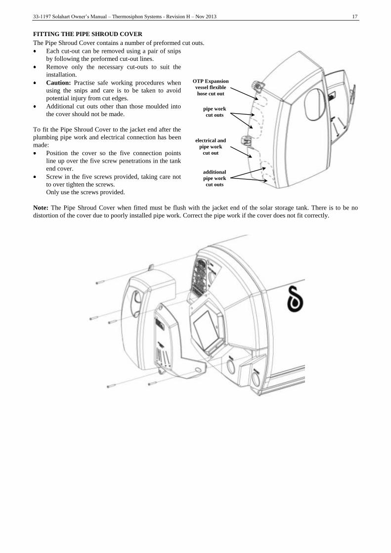
FITTING THE PIPE SHROUD COVER
The Pipe Shroud Cover contains a number of preformed cut outs.
Each cut-out can be removed using a pair of snips
by following the preformed cut-out lines.
Remove only the necessary cut-outs to suit the
installation.
Caution: Practise safe working procedures when
using the snips and care is to be taken to avoid
potential injury from cut edges.
Additional cut outs other than those moulded into
the cover should not be made.
To fit the Pipe Shroud Cover to the jacket end after the
plumbing pipe work and electrical connection has been
made:
Position the cover so the five connection points
line up over the five screw penetrations in the tank
end cover.
Screw in the five screws provided, taking care not
to over tighten the screws.
Only use the screws provided.
Note: The Pipe Shroud Cover when fitted must be flush with the jacket end of the solar storage tank. There is to be no
distortion of the cover due to poorly installed pipe work. Correct the pipe work if the cover does not fit correctly.
OTP Expansion
vessel flexible
hose cut out
pipe work
cut outs
electrical and
pipe work
cut out
additional
pipe work
cut outs

18 33-1197 Solahart Owner‟s Manual – Thermosiphon Systems - Revision H – Nov 2013
INSTALLATION INSTRUCTIONS – CLOSED CIRCUIT SERIES
WARNING: THE TANKS AND COLLECTORS ARE HEAVY. IMPROPER LIFTING TECHNIQUES COULD
RESULT IN PERSONAL INJURY DURING INSTALLATION. IT IS THE INSTALLER‟S RESPONSIBILITY TO
USE ONLY APPROVED LIFTING AND SAFETY DEVICES AND TECHNIQUES WHEN LIFTING COLLECTORS
AND TANKS ON ROOFS.
WARNING: DO NOT REMOVE THE SOLAR COLLECTOR PACKAGING COMPLETELY PRIOR TO THE
INSTALLATION AS THE SOLAR COLLECTOR SURFACE CAN BECOME VERY HOT. THIS WILL ASSIST IN
PREVENTING POTENTIAL PERSONAL INJURY AND ALSO PREVENT PREMATURE HEATING OF THE
HARTGARD SOLUTION PRIOR TO COMPLETION OF THE COMMISSIONING PROCESS. REMOVE ONLY
SUFFICIENT PACKAGING MATERIAL TO ENABLE THE INSTALLATION OF THE SOLAR COLLECTORS.
Select the location of the storage tank. The front mounting foot of the tank should be positioned directly over a tile batten.
Remove several tiles to expose the rafters and this batten.
Measure down 2050 mm (1270 mm for 301 & 221 Closed Circuit System) from the centre of the batten to determine the
location of the collector rail (refer to drawings, Page 51), mark this location. Remove several roofing tiles from this
location to expose the rafters. If more than two solar collectors are installed, locate the additional collector rail from the
parts kit adjacent to the first collector rail and join together using the drive cleat supplied in the parts kit.
Note: The collector / tank straps are to be fitted to the collector rail(s) before fixing the straps to the rafters.
Determine which slots in the collector rail(s) will be used for the collector straps. Hook two collector straps to the first
bottom collector rail and one collector strap to each additional single collector rail (short) (if used). Refer to “Hooking
Collector / Tank Strap to Collector Rail” on page 51 and Detail A on page 51.
Line up the straps with the rafters. After positioning the rail level, raise the left hand side 12 mm for each collector fitted
(i.e. 12 mm for a single collector system, 24 mm for a two collector system, 36 mm for a three collectors etc) and fix the
straps to the rafters. Replace the tiles.
Move back up to where the storage tank is to be positioned. If used, fit the tank flashing sheet under the top of the solar
collectors and extend up the roof to the top of the solar storage tank location. Place the flashing over this row of tiles and
tuck the top of the flashing under the row above.
Now using a lifting device, lift the collectors onto the roof and place them carefully into the collector rail. Remove the red
transit plugs from the collector sockets.
Join the collectors together using the collector connector assemblies (Part No. 33-7121). On systems that use conetite
fittings, ensure the fittings are fully inserted into the sockets before tightening the nuts. Only medium spanner pressure will
be required. The conetite fittings should be used only once. If for any reason, assemblies with conetite fittings need to be
removed, replace them completely with new assemblies.
Fit the fill assembly (Part No. 33-7134) and the collector bung assembly (Part No. 33-7135) into the bottom left and top
right hand corners (respectively) of the left and right hand collectors (respectively) using medium spanner pressure.
Centralise the collectors on the rail, and lock the collectors to the rail with the collector clamps (2 per collector) and
tighten, using the nuts and bolts provided.
For roof installations, slide the tank-to-collector spacers (Part No. 33-7144) over the top of the collectors. These should be
located 200 mm from the outer edge of the collectors, and on a high spot of the tiles (or profile for metal roofs).
Now using a lifting device, lift the tank onto the roof. Place the tank onto an aluminium flashing (if used) and locate the
tank central to the collectors before sliding it down onto the spacers.
Secure the tank to the roof rafters in a similar manner to that for the collectors, using the tank straps (Part No. 20-4600) and
the aluminium clamps (Part No. 33-0872). Loosely attach the tank clamps to the rear foot of the tank base, and clip in and
bolt the tank straps. Refer to “Hooking Collector / Tank Strap to Tank Clamp” and drawings on page 52. Ensure the bolt
heads fit into the valley of the tile.
Remove the yellow instruction label from the cold pipe. Fit the cold pipe first at the right hand side of the tank and insert
the other end of the pipe to the lower collector socket and tighten. Remove the yellow instruction label from the hot pipe.
Fit the hot pipe first at the left hand side of the tank. Tighten collector-side nut, before tightening tank-side nut. The floating
conetite should always be on the tank-side. Note that neither the hot nor the cold pipes (collector return and flow lines)
require insulation on these systems. It is recommended however insulation be fitted to these should the system be installed
on a metal or trafficable roof.
!
!

33-1197 Solahart Owner‟s Manual – Thermosiphon Systems - Revision H – Nov 2013 19
When in position, secure the tank straps to the roof rafters as for the collector strap. Ensure the straps are tight. Replace the
roof tiles. Fit the Temperature Pressure Relief Valve (Part No. 45-1104) into the tank as per water connection diagrams on
page 50.
If the installation involves the HartStat System this should now be fitted. Refer to “Systems Installed with an Over
Temperature Protection (OTP) System” on page 20 and to the installation instructions provided with the HartStat Kit for
details.
FIBRO CEMENT OR METAL SHEET ROOFING
Select a location for the storage tank, close to a purlin. Avoid locating tank at mid-span of sheeting. Fixing and assembly
procedures are similar to that detailed for tiled roofs, with the exception that the tank straps and the collector straps are
fixed with coach screws to the purlins below (refer to drawings, Page 41).
METAL TILED ROOF
Select a location for the storage tank. The front mounting foot of the tank should be positioned directly over a tile batten.
Fixing and assembly procedures are similar to that detailed for tiled roofs, except that the tank and collector straps are fixed
with spring head galvanised nails directly through the metal tiles into the rafters below. Seal under the straps with a
weatherproof mastic sealer.
INSTALLATIONS USING STANDS
Refer to installation sheet in the stand kit.
SPECIAL CONSIDERATIONS FOR COLD CLIMATES
In areas where air temperatures fall below -15ºC at any time or where snow will remain on the ground for more than 24
hours continuously, refer to your Solahart dealer for specific recommendations on suitability of location.
In areas subject to heavy snowfalls, care should be taken that snow cannot build up behind the tank and that the brackets
installed are capable of withstanding the expected snow loading. In these cases install the tank as close as possible to the
roof ridge.
Ensure that pipes and valves are located away from freeze locations wherever possible. Note that freezing of the valves can
permanently damage the valves. Take particular care at roof penetrations. Install the TRIO Valve and Cold Relief Valve
indoors (e.g. in the laundry) or in other locations not subject to freezing, but NOT in the ceiling space. If these valves are
located external to the building they must be insulated with at least 19 mm of elastomeric closed cell insulation, and sealed
to prevent entry of moisture.
In locations frequently subject to atmospheric temperature below -10ºC, hot and cold pipes and valves may freeze even
when insulated. It is recommended that in these locations, the cold pipes and valves to the Solahart storage tank and the hot
pipe from the tank should have electric heater tape under the insulation. The electric heater tape should have a heat output
of between 10 and 20 W/m. The tape should be a self-limiting tape such as “Raychem” and should be controlled by a
thermostat set at 0ºC. Connect the heater tape to a normally ON power supply.
FILLING AND COMMISSIONING OF THE STORAGE TANK
WARNING: DO NOT TURN ON ELECTRIC POWER UNTIL AFTER THE WATER HEATER HAS BEEN FILLED
WITH WATER.
Turn on at least one hot water outlet tap - preferably over a bath or laundry basin. Open the mains water supply tap on the
line to the water heater and allow the water to fill the storage cylinder displacing air out of the top of the cylinder through
the open tap. As soon as water flows freely (without air bursts) from the tap, close the tap and allow the cylinder to
pressurise. Check all joints for water tightness.
Turn on the electric power to the booster element ensuring that the power is correctly connected i.e. „Active‟ line to
„Active‟ terminal etc.
Operate both pressure relief valves‟ easing gears to ensure that the valves are functional. The storage tank is now filled and
ready to operate as an electric water heater. To operate as a solar water heater, the closed circuit must be commissioned by
an authorised Solahart installer or service contractor.
!

20 33-1197 Solahart Owner‟s Manual – Thermosiphon Systems - Revision H – Nov 2013
FILLING AND COMMISSIONING THE CLOSED CIRCUIT
The solar collectors and tank heat exchanger jacket are connected together to create a sealed, closed circuit that is entirely
separate from the potable water in the storage cylinder. The circuit is filled with „Hartgard‟ fluid. Under no circumstances
can any fluids other than „Hartgard‟ be used as the heat transfer fluid. Only potable water can be used in conjunction with
„Hartgard‟. Refer to the section on water quality on Page 3 of this manual. Should the water quality be above these limits,
then distilled or deionised water should be used.
Only Solahart trained and authorised installers are permitted to fill the closed fluid circuit. Refer to your Solahart dealer for
more information. For authorised installers, a special set of instructions and installation tools are provided.
WARNING: THE STORAGE TANK MUST BE FILLED WITH WATER BEFORE FILLING THE CLOSED
CIRCUIT.
Systems Installed with an Over Temperature Protection (OTP) System
An Over Temperature Protection system incorporates a HartStat valve. The HartStat valve is a temperature actuated valve
that is designed to close when exposed to high temperatures.
WARNING: APART FROM BEING AN OCCUPATIONAL HEALTH AND SAFETY CONCERN TO THE
INSTALLER, IF THE SOLAR COLLECTORS AND HARTSTAT VALVE ARE NOT COVERED DURING THE
COMMISSIONING PROCEDURE OF THE CLOSED CIRCUIT OF A THERMOSIPHON UNIT, IT IS POSSIBLE
FOR THE SOLAR COLLECTORS TO GENERATE ENOUGH HEAT TO CLOSE THE VALVE. THIS WILL
CREATE A VAPOUR LOCK THAT PREVENTS COMPLETE FILLING OF THE CLOSED CIRCUIT.
If the HartStat valve was to close and the closed circuit is only partially filled the solar performance can be severely
reduced resulting in a no hot water complaint. In addition, excessive noise can be generated from the system leading to
possible disturbance and irritation to the householders.
To avoid premature closure of the HartStat valve, the following instructions MUST BE followed during the commissioning
procedure and charging of the closed circuit.
Ensure the collectors are covered with the carton material. If not, securely cover the collectors with an opaque material.
This is to prevent solar gain and heating of the closed circuit fluid during the commissioning procedure.
Cover the HartStat valve with a cloth soaked in cold water. This is to keep the valve as cool as possible and ensure it
remains in the open position during the commissioning procedure.
Fill the system by the siphon method using a known quantity of fluid. Check this volume against the closed circuit volume
required for the system to ensure the correct amount of fluid has been added.
System Closed circuit
volume
System Closed circuit
volume
System Closed circuit
volume
System Closed circuit
volume
151 12 litres 221 14.5 litres 301 15.5 litres 443 30 litres
181 13.5 litres 222 18 litres 302 19 litres 444 34 litres
182 17 litres 303 23 litres
If the system is unable to take the correct amount of fluid then further investigation will be required to determine if the
HartStat OTP valve has closed or if there is a blockage in the system.
Instructions detailing the closed circuit commissioning process commences on Page 22.
!
!

33-1197 Solahart Owner‟s Manual – Thermosiphon Systems - Revision H – Nov 2013 21
PRECAUTIONS WITH HARTGARD FOR BUILDING WITH RAINWATER TANKS
While Hartgard is non toxic to humans, it does have an adverse effect on water stored in rainwater tanks. Hartgard will kill
microscopic algae that is typically present in rainwater tanks. This may then render the rainwater foul and unfit for human
consumption. Solahart recommends that installers ensure that rainwater tanks cannot be contaminated with Hartgard
solution. Before installing a closed circuit system, the installer should determine whether the run-off from the roof on which
the system will be mounted, is collected in a rainwater tank.
If this is the case, then the section of gutter immediately beneath the proposed location of the new Solahart system should
be isolated from the rainwater collection system. This can be done by blocking that section of gutter from the remaining
gutter, and fitting a separate down pipe to take any run-off water from that section of roof away to waste. If this is not
practical for a specific installation, then the installer should discuss the possible options with the home owner.
This should be done prior to installing the new system, so that any leak or spillage during installation does not make its way
into the rainwater tank. If a rainwater tank does become contaminated, then the following actions are necessary to return the
water supply to a consumable state.
a. Correct the leak or spillage.
b. Wash down the roof area where the spill or leak has occurred.
c. Flush out the gutters and down pipes.
d. Empty the rainwater tank, and clean out all algae from the inside of the tank.
e. Refill the rainwater tank with fresh water.
CLOSED CIRCUIT INDIRECT SYSTEMS – END CAP
The end cap is supplied fitted to the „tail‟ end of the tank. The end cap used should not need to be removed to complete the
installation.
Removing the End Cap
If it is necessary to remove the end cap:
Remove the screw from the end cap
Using a flat faced screwdriver, gently lever the end cap out of its recess from the key slot at the bottom of the end cap.
Fitting the End Cap
To fit the end cap:
Position the end cap in the jacket end recess, lining up the slot at the bottom of the end cap with the key on the jacket
end.
Gently push into the recess so the end cap engages with the ridges on the jacket end.
Secure the end cap with the screw provided, taking care not to over tighten the screw.
Only use the screw provided.
End cap closed circuit system Position end cap over recess and insert Secure end cap with screw
22 33-1197 Solahart Owner‟s Manual – Thermosiphon Systems - Revision H – Nov 2013
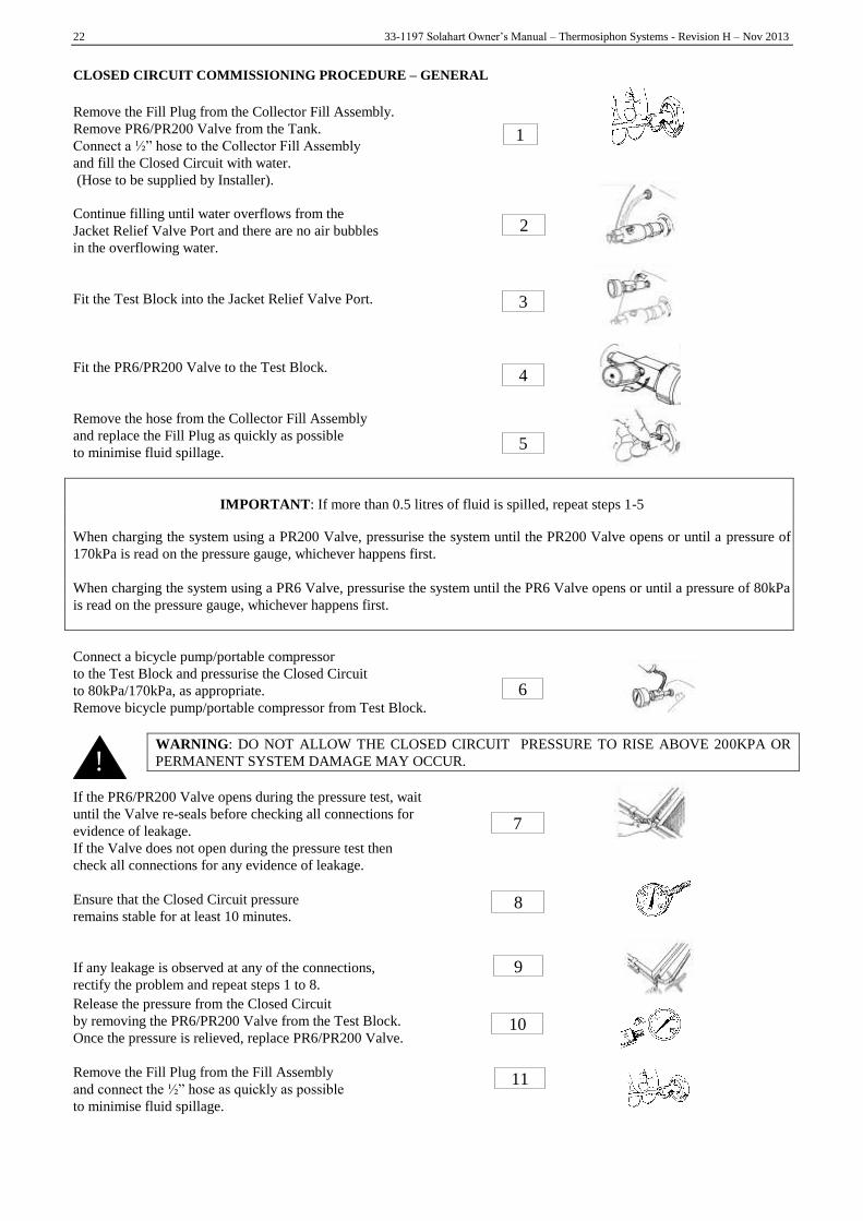
CLOSED CIRCUIT COMMISSIONING PROCEDURE – GENERAL
Remove the Fill Plug from the Collector Fill Assembly.
Remove PR6/PR200 Valve from the Tank.
Connect a ½” hose to the Collector Fill Assembly
and fill the Closed Circuit with water.
(Hose to be supplied by Installer).
Continue filling until water overflows from the
Jacket Relief Valve Port and there are no air bubbles
in the overflowing water.
Fit the Test Block into the Jacket Relief Valve Port.
Fit the PR6/PR200 Valve to the Test Block.
Remove the hose from the Collector Fill Assembly
and replace the Fill Plug as quickly as possible
to minimise fluid spillage.
IMPORTANT: If more than 0.5 litres of fluid is spilled, repeat steps 1-5
When charging the system using a PR200 Valve, pressurise the system until the PR200 Valve opens or until a pressure of
170kPa is read on the pressure gauge, whichever happens first.
When charging the system using a PR6 Valve, pressurise the system until the PR6 Valve opens or until a pressure of 80kPa
is read on the pressure gauge, whichever happens first.
Connect a bicycle pump/portable compressor
to the Test Block and pressurise the Closed Circuit
to 80kPa/170kPa, as appropriate.
Remove bicycle pump/portable compressor from Test Block.
WARNING: DO NOT ALLOW THE CLOSED CIRCUIT PRESSURE TO RISE ABOVE 200KPA OR
PERMANENT SYSTEM DAMAGE MAY OCCUR.
If the PR6/PR200 Valve opens during the pressure test, wait
until the Valve re-seals before checking all connections for
evidence of leakage.
If the Valve does not open during the pressure test then
check all connections for any evidence of leakage.
Ensure that the Closed Circuit pressure
remains stable for at least 10 minutes.
If any leakage is observed at any of the connections,
rectify the problem and repeat steps 1 to 8.
Release the pressure from the Closed Circuit
by removing the PR6/PR200 Valve from the Test Block.
Once the pressure is relieved, replace PR6/PR200 Valve.
Remove the Fill Plug from the Fill Assembly
and connect the ½” hose as quickly as possible
to minimise fluid spillage.
1
6
11
7
3
4
9
5
10
8
2
!

33-1197 Solahart Owner‟s Manual – Thermosiphon Systems - Revision H – Nov 2013 23
IMPORTANT: If more than 0.5 litres of fluid is spilled, repeat steps 1-5
Remove the PR6/PR200 Valve and siphon
the entire contents of the Hartgard container
into the Closed Circuit using the ½” hose.
Water will flow from the PR6/PR200 Valve Port
during this operation
(4.5 litres for each container of Hartgard).
When the Hartgard container is empty, flush approx 1 litre
of clean water through the hose into the Collector
(to ensure all of the Hartgard has been siphoned into
the system), and refit the PR6/PR200 Valve to the Test Block.
Remove the hose from the Fill Assembly and
screw in the Fill Plug as quickly as possible
to minimise fluid spillage.
IMPORTANT: If more than 0.5 litres of fluid is spilled, repeat steps 1-5
When charging the system using a PR200 Valve, pressurise the system until the PR200 Valve opens or until a pressure of
170kPa is read on the pressure gauge, whichever happens first.
When charging the system using a PR6 Valve, pressurise the system until the PR6 Valve opens or until a pressure of 80kPa
is read on the pressure gauge, whichever happens first.
Pressurise the Closed Circuit to 80kPa/170kPa,
as appropriate, using the bicycle pump/portable compressor
and ensure there is no leak at the Fill Assembly.
Remove bicycle pump/portable compressor from Test Block.
Ensure that the pressure remains stable
for at least 10 minutes.
Release the pressure from the Closed Circuit by
removing the PR6/PR200 Valve from the Test Block.
Remove the Test Block from the Tank.
Fit the PR6/PR200 Valve to the Jacket Relief Valve Port
when ready or as soon as water starts to be expelled
(440 systems).
The closed circuit system is now ready for operation.
Remove the solar collector packaging. This must be removed completely prior to the permanent operation of the water
heater.
16
12
13
18
14
19
15
20
17

24 33-1197 Solahart Owner‟s Manual – Thermosiphon Systems - Revision H – Nov 2013
INSTALLATION INSTRUCTIONS – OPEN CIRCUIT SERIES
WARNING: THE TANKS AND COLLECTORS ARE HEAVY. IMPROPER LIFTING TECHNIQUES COULD
RESULT IN PERSONAL INJURY DURING INSTALLATION. IT IS THE INSTALLER’S RESPONSIBILITY TO
USE ONLY APPROVED LIFTING AND SAFETY DEVICES AND TECHNIQUES WHEN LIFTING COLLECTORS
AND TANKS ON ROOFS.
WARNING: DO NOT REMOVE THE SOLAR COLLECTOR PACKAGING COMPLETELY PRIOR TO THE
INSTALLATION AS THE SOLAR COLLECTOR SURFACE CAN BECOME VERY HOT. THIS WILL ASSIST IN
PREVENTING POTENTIAL PERSONAL INJURY DURING THE COMMISSIONING PROCESS. REMOVE ONLY
SUFFICIENT PACKAGING MATERIAL TO ENABLE THE INSTALLATION OF THE SOLAR COLLECTORS.
Select the location of the storage tank. The front mounting foot of the tank should be positioned directly over a tile batten.
Remove several tiles to expose the rafters and this batten. Measure 2050 mm down (1170 mm for 301L & 221L) from the
centre of the batten to determine the location of the collector rail. (refer to drawings, Page 51) Mark this location. Remove
several roofing tiles from this location to expose the rafters. If more than two solar collectors are installed, locate the
additional collector rail from the parts kit adjacent to the first collector rail and join together using the drive cleat supplied
in the parts kit.
Note: The collector / tank straps are to be fitted to the collector rail(s) before fixing the straps to the rafters.
Determine which slots in the collector rail(s) will be used for the collector straps. Hook two collector straps to the first
bottom collector rail and one collector strap to each additional single collector rail (short) (if used). Refer to “Hooking
Collector / Tank Strap to Collector Rail” on page 51 and Detail A on page 51.
Line up the straps with the rafters. After positioning the rail level, raise the right hand side 12 mm for each collector fitted
(i.e. 12 mm for a single collector system, 24 mm for a two collector system, 36 mm for a three collector system etc) and fix
the straps to the rafters. Replace the tiles (refer to drawings, Page 51).
Move back up to where the storage tank is to be positioned. If used, fit the tank flashing sheet under the top of the solar
collectors and extend up the roof to the top of the solar storage tank location. Place the flashing over this row of tiles and
tuck the top of the flashing under the row above. Now using a lifting device lift collectors onto the roof. Place the collectors
carefully into collector rail. Remove the red transit plugs from the collector with a screwdriver. Silicon O-rings are supplied
in the Parts Box and must be fitted at each pipe connection.
Join the collectors using the collector unions provided (Part No. 33-0695 – screwed fitting, 34-1390 – conetite fitting).
Apply only medium pressure with a spanner to tighten. Centralise the collectors on the rail. Lock the collectors to the rail
with the collector clamps (2 per collector). Tighten using the nuts and bolts provided. Fit either the copper blanking discs
(Part No. 33-0606) and collector nuts (Part No. 33-0600) for collectors with screwed fittings or the collector bung assembly
(Part No. 34-1391) for collectors with conetite fittings into the top left hand corner of the left hand collector and into the
bottom right hand corner of the right hand collector.
Now use a lifting device to lift the tank onto the roof. Place the tank onto the aluminium flashing (if used), central to the
collectors. Fit the collector hot pipe into the top right hand corner of the right hand collector. Fit the collector cold pipe into
the lower left hand corner of the left hand collector. After lining up the connecting pipes with the tank, fit the hot pipe (refer
to “Open Circuit Direct Systems – End Cap” on page 25). Fit the cold pipe to the tank cold inlet socket. Refer to “Open
Circuit Direct Systems – Thermosiphon Restrictor Valve (TRV)” on page 26 if a Thermosiphon Restrictor Valve (TRV) is
to be installed in the cold pipe.
Secure the tank to the roof rafters in a similar manner to that for the collectors, using the tank straps (Part No. 20-4600) and
the aluminium clamps (Part No. 33-0872). Loosely attach the tank clamps to the rear foot of the tank base, and clip in and
bolt the tank straps. Refer to “Hooking Collector / Tank Strap to Tank Clamp” and drawings on page 52. Ensure the bolt
heads fit into the valley of the tile. Ensure straps are tight. Replace roof tiles.
Fit the temperature pressure relief valve (Part No. 45-1104) into the tank as per the connection diagram on page 50.
Fit the pipe shroud cover if supplied. Refer to “Thermosiphon Pipe Shroud Cover” on page 16.
WARNING: UNCOATED DR BRASS CONETITE FITTINGS MUST ONLY BE USED IF LCS
COLLECTORS ARE BEING INSTALLED WITH AN OPEN CIRCUIT SYSTEM.
!
!
!

33-1197 Solahart Owner‟s Manual – Thermosiphon Systems - Revision H – Nov 2013 25
FIBRO CEMENT OR METAL SHEET ROOFING
Select a location for the storage tank close to a purlin. Avoid locating tank at mid-span of sheeting. Fixing and assembly
procedures are similar to that detailed for tiled roofs, with the exception that the tank straps and the collector straps are
fixed with coach screws to the purlins below (refer to drawings, Page 51).
METAL TILED ROOF
Select a location for the storage tank. The front mounting foot of the tank should be positioned directly over a tile batten.
Fixing and assembly procedures are similar to that detailed for tiled roofs, except that the tank and collector straps are fixed
with spring head galvanised nails directly through the metal tiles into the rafters below. Seal under the straps with a
weatherproof mastic sealer.
STANDS
Refer to installation sheet in the stand kit.
OPEN CIRCUIT DIRECT SYSTEMS – END CAP
The end cap is supplied fitted to the „tail‟ end of the tank. The end cap used on the open circuit direct system has an
opening to enable the solar hot pipe to be connected to the solar storage tank.
Installing the Solar Hot Pipe
When installing the solar hot pipe with the end cap in position, ensure:
There is suitable access to the flats on the solar hot pipe fitting nut to enable it to be fitted securely
Scoring of the end cap by the tool does not occur when screwing in the fitting
The connection does not leak.
Removing the End Cap
The end cap can be removed from the jacket end if required to allow the fitting of the solar hot pipe.
If it is necessary to remove the end cap:
Remove the screw from the end cap
Using a flat faced screwdriver, gently lever the end cap out of its recess from the key slot at the bottom of the end cap.
Fitting the End Cap
To fit the end cap with the solar hot pipe:
Place the end cap over the solar hot pipe with the flat face away from the solar storage tank.
It may be necessary to slide the end cap down the solar hot pipe to allow access to the fitting nut on the pipe.
Fit the solar hot pipe to the solar storage tank.
Slide the end cap back up the solar hot pipe and position in the jacket end recess, lining up the slot at the bottom of the
end cap with the key on the jacket end.
Gently push into the recess so the end cap engages with the ridges on the jacket end.
Secure the end cap with the screw provided, taking care not to over tighten the screw.
Only use the screw provided.
Position end cap
and solar hot pipe
Place end cap
over solar hot pipe
Fit solar hot pipe
to tank
Secure end cap
with screw

26 33-1197 Solahart Owner‟s Manual – Thermosiphon Systems - Revision H – Nov 2013
OPEN CIRCUIT DIRECT SYSTEMS – THERMOSIPHON RESTRICTOR VALVE (TRV)
A Thermosiphon Restrictor Valve (TRV) is available for use on an open circuit direct system to assist with over
temperature protection of the system. The TRV locates in the top end of the cold pipe assembly. A non-standard cold pipe
arrangement is required to accommodate the TRV.
In Australia, a TRV must be used on a new installation of a 222, 303, 443 system regardless of the type of collector
installed and on a 302 system installed with LCS collectors.
When assembling the cold pipe, ensure:
A Silicone Rubber Washer is used between the flared pipe ends and each end of the TRV.
The TRV is to be orientated with the copper element probe facing upward toward the tank. The TRV has an arrow and
the word „FLOW‟ stamped on the outside of the body. The arrow is to point upwards in the direction of the tank.
If this pipe assembly is being retrospectively fitted to an existing system, replace existing O-Rings with the new ones
to seal cold pipe to the tank/collector and extension pipe (if any).
Thermosiphon Restrictor Valve (TRV) Assembly
Cold Pipe Assy
TRV Lower
Cold Pipe Assy
TRV Upper
CAUTION!
DO NOT OVERTIGHTEN FITTINGS.
HANDTIGHTEN, THEN ADD HALF TURN
ONLY WITH SPANNER, OTHERWISE
DAMAGE TO WASHER MAY OCCUR.
Cold Water Inlet
34-4391 (TRV)
The arrow stamped on the
TRV body is to point
toward the tank
To Tank Inlet
(Or Extension Pipe)
33-0171
(O-Ring)
34-5096
(Silicone Rubber Washer)

33-1197 Solahart Owner‟s Manual – Thermosiphon Systems - Revision H – Nov 2013 27
INSTALLATIONS INCLUDING TEMPERATURE LIMITING DEVICES
In the event of the collectors stagnating and generating steam, it is possible that high temperature water may by-pass the
temperature limiting device. To prevent this from occurring please follow the connection details shown below.
Where a temperature limiting device is installed adjacent to the solar water heater, the cold water line to the temperature
limiting device can be branched off the cold water line either before or after the isolation valve and pressure limiting valve
to the solar storage tank, but it MUST BE before the non return valve prior to an open circuit direct system. The cold water
line to the temperature limiting device can be branched off the cold water line either before or after the non return valve
prior to a closed circuit indirect system. If an expansion control valve is required, it must always be installed after the non
return valve and be the last valve prior to the solar storage tank.
WARNING: A NON RETURN VALVE MUST BE INSTALLED ON THE COLD WATER LINE TO THE SOLAR
STORAGE TANK AFTER THE COLD WATER BRANCH TO A TEMPERATURE LIMITING DEVICE PRIOR TO
AN OPEN CIRCUIT DIRECT SYSTEM.
If a combination isolation valve and non return valve (duo or trio valve) is installed on the cold water line to the solar water
heater and the cold water line to the temperature limiting device branches off after this valve prior to an open circuit direct
system, then a second non return valve must be installed between the cold water branch and the solar storage tank.
If a pressure limiting valve is installed on the cold water line to the solar water heater and the cold water line to a
temperature limiting device branches off before this valve or from another cold water line in the premises, then a pressure
limiting valve of an equal pressure setting may be required prior to the temperature limiting device (refer to the temperature
limiting device‟s installation manual for detail of acceptable pressure differentials).
FILLING AND COMMISSIONING THE STORAGE TANK AND COLLECTORS
WARNING: DO NOT TURN ON ELECTRIC POWER UNTIL AFTER THE WATER HEATER HAS BEEN FILLED
WITH WATER.
Turn on a least one hot water outlet tap, preferably over a bath or laundry basin. Open the mains water supply valve on the
line to the water heater to allow water to fill the storage cylinder and collectors, dispelling air out of the top of the cylinder
through the open tap. As soon as water flows freely (without air bursts) from the tap, close the tap and allow the cylinder to
pressurise. Check all joints for water tightness.
Turn ON the electric power to the booster element ensuring that the power is correctly connected i.e. „Active‟ line to
„Active‟ terminal etc.
Operate the easing lever on both pressure relief valves to ensure that the valves are functional. The system tank is now
filled and ready to operate.
Remove the solar collector packaging. This must be removed completely prior to the permanent operation of the water
heater.
!
!

28 33-1197 Solahart Owner‟s Manual – Thermosiphon Systems - Revision H – Nov 2013
TECHNICAL SPECIFICATIONS
Systems151L & 151L
FREE HEAT151J 151KF
181L & 181L
FREE HEAT
181J & 181J
FREE HEAT
181KF & 181KF
FREE HEAT
181BTC &
181BTC
FREE HEAT
182L & 182L
FREE HEAT
182J & 182J
FREE HEAT
Delivery litres 130 130 130 160 160 160 160 160 160
(solar) US gal. 34 34 34 42 42 42 42 42 42
Auxiliary litres 75 75 75 90 90 90 90 90 90
boost US gal. 20 20 20 23 23 23 23 23 23
Weight kg 239 256 256 275 292 292 279 311 337
(full) lbs 527 564 564 606 644 644 615 685 743
Weight kg 86 102 102 92 108 108 97 125 153
(empty) lbs 190 225 225 203 238 238 214 276 337
Length m 2.475 2.475 2.475 2.475 2.475 2.475 2.475 2.475 2.475
in 97.5 97.5 97.5 97.5 97.5 97.5 97.5 97.5 97.5
Height m 0.51 0.51 0.51 0.51 0.51 0.51 0.51 0.51 0.51
in 20.1 20.1 20.1 20.1 20.1 20.1 20.1 20.1 20.1
Width m 1.29 1.29 1.29 1.485 1.485 1.485 1.485 2.31 2.31
in 50.8 50.8 50.8 58.5 58.5 58.5 58.5 90.9 90.9
Working kPa 1000 1000 1000 1000 1000 1000 1000 1000 1000
Pressure psi 145 145 145 145 145 145 145 145 145
Tank type 150L or 150LF 150J 150J 180L or 180LF 180J or 180F 180J or 180F 180J or 180F 180L or 180LF 180J or 180F
Type of Collector L J KF L J KF BT L J
Number of Collectors 1 1 1 1 1 1 1 2 2
Systems182KF & 182KF
FREE HEAT
221L & 221L
FREE HEAT
221J & 221J
FREE HEAT
221KF & 221 KF
FREE HEAT
222L & 222L
FREE HEAT
222J & 222J
FREE HEAT
222KF & 222 KF
FREE HEAT
301L & 301L
FREE HEAT
301J & 301J
FREE HEAT
Delivery litres 160 200 200 200 200 200 200 260 260
(solar) US gal. 42 52 52 52 52 52 52 68 68
Auxiliary litres 90 110 110 110 110 110 110 150 150
boost US gal. 23 29 29 29 29 29 29 39 39
Weight kg 338 324 347 347 324 347 347 421 448
(full) lbs 745 714 765 765 714 765 765 928 987
Weight kg 154 101 123 123 101 123 123 118 144
(empty) lbs 339 223 271 271 223 271 271 260 317
Length m 2.475 2.475 2.475 2.475 2.475 2.475 2.475 2.475 2.475
in 97.5 97.5 97.5 97.5 97.5 97.5 97.5 97.5 97.5
Height m 0.51 0.51 0.51 0.51 0.51 0.51 0.51 0.51 0.51
in 20.1 20.1 20.1 20.1 20.1 20.1 20.1 20.1 20.1
Width m 2.31 1.76 1.76 1.76 1.76 1.76 1.76 2.31 2.31
in 90.9 69.3 69.3 69.3 69.3 69.3 69.3 90.9 90.9
Working kPa 1000 1000 1000 1000 1000 1000 1000 1000 1000
Pressure psi 145 145 145 145 145 145 145 145 145
Tank type 180J or 180F 220L or 220LF 220J or 220F 220J or 220F 220L or 220LF 220J or 220F 220J or 220F 300L or 300LF 300J or 300F
Type of Collector KF L J KF L J KF L J
Number of Collectors 2 1 1 1 2 2 2 1 1
Systems301KF & 301KF
FREE HEAT
302L & 302L
FREE HEAT
302LCSD &
302LCSD
FREE HEAT
302J & 302J
FREE HEAT
302KF & 302KF
FREE HEAT
302BTC &
302BTC FREE
HEAT
302LCSC &
302LCSC
FREE HEAT
303L & 303L
FREE HEAT
303J & 303J
FREE HEAT
Delivery litres 260 260 260 260 260 260 260 260 260
(solar) US gal. 68 68 68 68 68 68 68 68 68
Auxiliary litres 150 150 150 150 150 150 150 150 150
boost US gal. 39 39 39 39 39 39 39 39 39
Weight kg 448 457 451 495 495 469 469 493 540
(full) lbs 987 1007 995 1091 1091 1044 1044 1087 1190
Weight kg 144 151 147 186 186 164 164 184 228
(empty) lbs 317 333 324 410 410 362 362 406 503
Length m 2.475 2.475 2.475 2.475 2.475 2.475 2.475 2.475 2.475
in 97.5 97.5 97.5 97.5 97.5 97.5 97.5 97.5 97.5
Height m 0.51 0.51 0.51 0.51 0.51 0.51 0.51 0.51 0.51
in 20.1 20.1 20.1 20.1 20.1 20.1 20.1 20.1 20.1
Width m 2.31 2.31 2.31 2.31 2.31 2.31 2.31 3.16 3.16
in 90.9 90.9 90.9 90.9 90.9 90.9 90.9 124.4 124.4
Working kPa 1000 1000 1000 1000 1000 1000 1000 1000 1000
Pressure psi 145 145 145 145 145 145 145 145 145
Tank type 300J or 300F 300L or 300LF 300L or 300LF 300J or 300F 300J or 300F 300J or 300F 300J or 300F 300L or 300LF 300J or 300F
Type of Collector KF L LCS J KF BT LCS L J
Number of Collectors 1 2 2 2 2 2 2 3 3
Notes: Solar Delivery: typical draw from field tests, methodology analogous to AS1056.1

33-1197 Solahart Owner‟s Manual – Thermosiphon Systems - Revision H – Nov 2013 29
Systems303KF & 303KF
FREE HEAT
303LCSC &
303LCSC
FREE HEAT
443L & 443L
FREE HEAT
443J & 443J
FREE HEAT
443KF & 443KF
FREE HEAT
443BTC &
443BTC
FREE HEAT
444L & 444L
FREE HEAT
444J & 444J
FREE HEAT
444KF & 444KF
FREE HEAT
Delivery litres 260 260 400 400 400 400 400 400 400
(solar) US gal. 68 68 105 105 105 105 105 105 105
Auxiliary litres 150 150 200 200 200 200 200 200 200
boost US gal. 39 39 53 53 53 53 53 53 53
Weight kg 552 513 676 730 730 691 712 775 788
(full) lbs 1217 1131 1490 1609 1609 1524 1569 1708 1737
Weight kg 229 196 250 289 289 256 260 319 332
(empty) lbs 505 432 551 637 637 565 573 703 732
Length m 2.475 2.475 2.475 2.475 2.475 2.475 2.475 2.475 2.475
in 97.5 97.5 97.5 97.5 97.5 97.5 97.5 97.5 97.5
Height m 0.51 0.51 0.51 0.51 0.51 0.51 0.51 0.51 0.51
in 20.1 20.1 20.1 20.1 20.1 20.1 20.1 20.1 20.1
Width m 3.16 3.16 3.34 3.34 3.34 3.34 4.36 4.36 4.36
in 124.4 124.4 131.5 131.5 131.5 131.5 171.8 171.8 171.8
Working kPa 1000 1000 1000 1000 1000 1000 1000 1000 1000
Pressure psi 145 145 145 145 145 145 145 145 145
Tank type 300J or 300F 300J or 300F 440L or 440LF 440J or 440F 440J or 440F 440J or 440F 440L or 440LF 440J or 440F 440J or 440F
Type of Collector KF LCS L J KF BT L J KF
Number of Collectors 3 3 3 3 3 3 4 4 4
Notes: Solar Delivery: typical draw from field tests, methodology analogous to AS1056.1
Tanks150L &
150LF150J
180L &
180LF180J 180F
220L &
220LF220J 220F
300L &
300LF300J 300F
Capacity litres 150 150 180 180 180 220 220 220 300 300 300
US gal. 40 40 48 48 48 58 58 58 80 80 80
Weight kg 199 206 235 245 246 284 297 298 381 398 399
(full) lbs 439 454 518 540 542 626 655 657 840 877 879
Weight kg 49 56 55 65 66 64 77 78 81 98 99
(empty) lbs 108 123 121 143 145 141 170 172 179 216 218
Length m 1.28 1.28 1.494 1.494 1.494 1.76 1.76 1.76 2.31 2.31 2.31
in 50.4 50.4 58.8 58.8 58.8 69.3 69.3 69.3 91 91 91
Height & m 0.51 0.51 0.51 0.51 0.51 0.51 0.51 0.51 0.51 0.51 0.51
width in 20.1 20.1 20.1 20.1 20.1 20.1 20.1 20.1 20.1 20.1 20.1
Tanks440L &
440LF440J 440F Collectors L LCS BT J KF
Capacity litres 405 405 405 Aperture m2
1.86 1.86 1.86 1.86 1.86
US gal. 107 107 107 ft2
20 20 20 20 20
Weight kg 531 531 531 Capacity litres 1.5 2 2.1 3.8 3.8
(full) lbs 1171 1171 1171 US gal. 0.396 0.528 0.554 1.003 1.003
Weight kg 124 147 148 Weight kg 31 33 33 46 46
(empty) lbs 273 324 324 (full) lbs 68 72 72 101 101
Length m 3.285 3.285 3.285 Weight kg 29 31 31 42 42
in 129.3 129.3 129.3 (empty) lbs 64 68 68 93 93
Height & m 0.51 0.51 0.51 Length m 1.941 1.941 1.941 1.941 1.941
width in 20.1 20.1 20.1 in 76.41 76.41 76.41 76.41 76.41
Depth m 0.08 0.08 0.08 0.08 0.08
Cylinder material Steel, low carbon, 2.5 mm (0.1") in 3.14 3.14 3.14 3.14 3.14
Cylinder lining Primaglaze: ceramic vitreous enamel, 2 coats Width m 1.023 1.023 1.023 1.023 1.023
Insulation Polyurethane: pressure injected foam, zero CFC in 40.27 40.27 40.27 40.27 40.27
Case Aluminium: 0.4 mm (0.2") Working kPa 1400 1400 1400 200 200
End caps Polypropylene: carbon black, UV stabilised pressure psi 203 203 203 29 29
Anode Magnesium, sacrificial, with steel core Test kPa 300 300 300 450 450
pressure psi 43 43 43 65 65
No of risers 7 6 13 35 35
Type: Copper sheath, immersion Riser material Copper Copper Copper Steel Steel
Rating (kW):1.8, 2.4, 3.0, 3.6, 4.8 Absorber material Aluminium Aluminium Copper Steel Steel
Supply Voltage: 220V - 250V Absorber surface P* S* S* P* C*
Tray: Aluminium: 0.7 mm P* = Polyester powder coat
Insulation: Polyester: 38mm - L and J C* = Chromonyx selective surface
Glasswool: 38mm - LCS, BT, KF S* = Sputtered selective surface
Glass: Tempered Low Iron,
3.2mm thick
Auxilliary Electric Booster

30 33-1197 Solahart Owner‟s Manual – Thermosiphon Systems - Revision H – Nov 2013
ANNUAL PERFORMANCE CALCULATIONS FOR EUROPE
SYSTEM WIND AND SNOW LOAD PRESSURE
Under the requirements of EN 12795-1 (European Standard) the type of collector used in these systems has been tested
(ITW 11COL1015) to 2000 Pa, the maximum pressure (positive and negative) limit of the test equipment. This value has
been used to determine the maximum permissible limits of wind load (vm) as 56.6 m/s (203.6 km/h) and snow load (sk) as 2
kN/m2.
Systems or collector only installations using these collectors are only to be installed where the maximum values of sk (snow
load) and vm (mean wind velocity) for the specific geographical area and installation circumstances do not exceed the
European permissible limit of wind and snow load. Values of vm and sk for your area can be obtained by consulting the local
dealer, a qualified structural engineer or relevant authorities.
These collectors and systems are routinely used in Australian Cyclonic regions.
KF SYSTEMS
Annual performance calculations of Solahart thermosiphon KF systems with the KF collector according to EN12976
SolarKeyMark Systems ITW Test Report 10SYS90-1 and 09SYS72 for the 151KF (150 tank, 1 collector), 181KF (180
tank, 1 collector), 182KF (180 tank, 2 collectors), 221KF (220 tank, 1 collector), 222KF (220 tank, 2 collectors), 301KF
(300 tank, 1 collector), 302KF (300 tank, 2 collectors), 303KF (300 tank, 3 collectors), 443KF (440 tank, 3 collectors)
systems and 444KF (440 tank, 4 collectors) systems.
Qd = energy demand QL = solar energy (load) f-sol = solar fraction
Model 151KF 151KF 151KF 151KF
Demand 80 litres / day 110 litres / day 140 litres / day 200 litres / day
Location Qd
MJ/a
QL
MJ/a
f-sol
%
Qd
MJ/a
QL
MJ/a
f-sol
%
Qd
MJ/a
QL
MJ/a
f-sol
%
Qd
MJ/a
QL
MJ/a
f-sol
%
Stockholm 59.6°N 4441 2367 53.3 6107 2925 47.9 7772 3334 42.9 11103 3708 33.4
Wurzburg 49.5°N 4257 2512 59.0 5854 3167 54.1 7450 3658 49.1 10643 4193 39.4
Davos 46.8°N 4820 3726 77.3 6628 4606 69.5 8435 5204 61.7 12050 5712 47.4
Athens 38.0°N 3305 2961 89.6 4545 3831 84.3 5784 4546 78.6 8263 5553 67.2
Model 181KF 181KF 181KF 181KF
Demand 110 litres / day 140 litres / day 170 litres / day 200 litres / day
Location Qd
MJ/a
QL
MJ/a
f-sol
%
Qd
MJ/a
QL
MJ/a
f-sol
%
Qd
MJ/a
QL
MJ/a
f-sol
%
Qd
MJ/a
QL
MJ/a
f-sol
%
Stockholm 59.6°N 6107 2852 46.7 7772 3233 41.6 9438 3492 37.0 11103 3631 32.7
Wurzburg 49.5°N 5854 3091 52.8 7450 3561 47.8 9047 3917 43.3 10643 4108 38.6
Davos 46.8°N 6628 4441 67.0 8435 4994 59.2 10243 5347 52.2 12050 5531 45.9
Athens 38.0°N 4545 3186 70.1 5784 3765 65.1 7024 4228 60.2 8263 4569 55.3
Model 182KF 182KF 182KF 182KF
Demand 80 litres / day 110 litres / day 140 litres / day 200 litres / day
Location Qd
MJ/a
QL
MJ/a
f-sol
%
Qd
MJ/a
QL
MJ/a
f-sol
%
Qd
MJ/a
QL
MJ/a
f-sol
%
Qd
MJ/a
QL
MJ/a
f-sol
%
Stockholm 59.6°N 4441 2718 61.2 6107 3524 57.7 7772 4244 54.6 11103 5363 48.3
Wurzburg 49.5°N 4257 2823 66.3 5854 3688 63.0 7450 4478 60.1 10643 5790 54.4
Davos 46.8°N 4820 4227 87.7 6628 5560 83.9 8435 6740 79.9 12050 8507 70.6
Athens 38.0°N 3305 3143 95.1 4545 4240 93.3 5784 5269 91.1 8263 7015 84.9
Model 221KF 221KF 221KF 221KF
Demand 140 litres / day 200 litres / day 250 litres / day 300 litres / day
Location Qd
MJ/a
QL
MJ/a
f-sol
%
Qd
MJ/a
QL
MJ/a
f-sol
%
Qd
MJ/a
QL
MJ/a
f-sol
%
Qd
MJ/a
QL
MJ/a
f-sol
%
Stockholm 59.6°N 7772 3381 43.5 11103 3886 35.0 13879 4080 29.4 16655 4180 25.1
Wurzburg 49.5°N 7450 3703 49.7 10643 4374 41.1 13304 4630 34.8 15965 4757 29.8
Davos 46.8°N 8435 5230 62.0 12050 5941 49.3 15063 6221 41.3 18075 6362 35.2
Athens 38.0°N 5784 4564 78.9 8263 5701 69.0 10329 6352 61.5 12395 6705 54.1

33-1197 Solahart Owner‟s Manual – Thermosiphon Systems - Revision H – Nov 2013 31
Model 222KF 222KF 222KF 222KF
Demand 140 litres / day 200 litres / day 250 litres / day 300 litres / day
Location Qd
MJ/a
QL
MJ/a
f-sol
%
Qd
MJ/a
QL
MJ/a
f-sol
%
Qd
MJ/a
QL
MJ/a
f-sol
%
Qd
MJ/a
QL
MJ/a
f-sol
%
Stockholm 59.6°N 7772 4314 55.5 11103 5529 49.8 13879 6218 44.8 16655 6645 39.9
Wurzburg 49.5°N 7450 4545 61.0 10643 5939 55.8 13304 6798 51.1 15965 7376 46.2
Davos 46.8°N 8435 6832 81.0 12050 8748 72.6 15063 9806 65.1 18075 10375 57.4
Athens 38.0°N 5784 5310 91.8 8263 7139 86.4 10329 8366 81.0 12395 9333 75.3
Model 301KF 301KF 301KF 301KF
Demand 200 litres / day 250 litres / day 300 litres / day 400 litres / day
Location Qd
MJ/a
QL
MJ/a
f-sol
%
Qd
MJ/a
QL
MJ/a
f-sol
%
Qd
MJ/a
QL
MJ/a
f-sol
%
Qd
MJ/a
QL
MJ/a
f-sol
%
Stockholm 59.6°N 11103 3930 35.4 13879 4191 30.2 16655 16655 26.2 22206 22206 20.3
Wurzburg 49.5°N 10643 4427 41.6 13304 4749 35.7 15965 15965 31.0 21286 21286 24.2
Davos 46.8°N 12050 5958 49.7 15063 6371 42.3 18075 18075 36.6 24100 24100 28.4
Athens 38.0°N 8263 5735 69.4 10329 6476 62.7 12395 12395 56.1 16526 16526 44.1
Model 302KF 302KF 302KF 302KF
Demand 200 litres / day 250 litres / day 300 litres / day 400 litres / day
Location Qd
MJ/a
QL
MJ/a
f-sol
%
Qd
MJ/a
QL
MJ/a
f-sol
%
Qd
MJ/a
QL
MJ/a
f-sol
%
Qd
MJ/a
QL
MJ/a
f-sol
%
Stockholm 59.6°N 11103 5540 49.9 13879 6259 45.1 16655 6762 40.6 22206 7173 32.3
Wurzburg 49.5°N 10643 5949 55.9 13304 6838 51.4 15965 7503 47.0 21286 8131 38.2
Davos 46.8°N 12050 8688 72.1 15063 9776 64.9 18075 10465 57.9 24100 10966 45.5
Athens 38.0°N 8263 7114 86.1 10329 8366 81.0 12395 9383 75.7 16526 10841 65.6
Model 303KF 303KF 303KF 303KF
Demand 200 litres / day 250 litres / day 300 litres / day 400 litres / day
Location Qd
MJ/a
QL
MJ/a
f-sol
%
Qd
MJ/a
QL
MJ/a
f-sol
%
Qd
MJ/a
QL
MJ/a
f-sol
%
Qd
MJ/a
QL
MJ/a
f-sol
%
Stockholm 59.6°N 11103 6207 55.9 13879 7300 52.6 16655 8211 49.3 22206 9371 42.2
Wurzburg 49.5°N 10643 6535 61.4 13304 7769 58.4 15965 8828 55.3 21286 10345 48.6
Davos 46.8°N 12050 9833 81.6 15063 11598 77.0 18075 12996 71.9 24100 14725 61.1
Athens 38.0°N 8263 7610 92.1 10329 9224 89.3 12395 10647 85.9 16526 12890 78.0
Model 443KF 443KF 443KF 443KF
Demand 250 litres / day 300 litres / day 400 litres / day 600 litres / day
Location Qd
MJ/a
QL
MJ/a
f-sol
%
Qd
MJ/a
QL
MJ/a
f-sol
%
Qd
MJ/a
QL
MJ/a
f-sol
%
Qd
MJ/a
QL
MJ/a
f-sol
%
Stockholm 59.6°N 13879 7883 56.8 16655 8960 53.8 22206 10637 47.9 33309 12091 36.3
Wurzburg 49.5°N 13304 7942 59.7 15965 9084 56.9 21286 10941 51.4 31929 12804 40.1
Davos 46.8°N 15063 11854 78.7 18075 13412 74.2 24100 15689 65.1 36150 17497 48.4
Athens 38.0°N 10329 9337 90.4 12395 10845 87.5 16526 13403 81.1 24789 16857 68.8
Model 444KF 444KF 444KF 444KF
Demand 250 litres / day 300 litres / day 400 litres / day 600 litres / day
Location Qd
MJ/a
QL
MJ/a
f-sol
%
Qd
MJ/a
QL
MJ/a
f-sol
%
Qd
MJ/a
QL
MJ/a
f-sol
%
Qd
MJ/a
QL
MJ/a
f-sol
%
Stockholm 59.6°N 13879 8036 57.9 16655 9227 55.4 22206 11236 50.6 33309 13557 40.7
Wurzburg 49.5°N 13304 8408 63.2 15965 9738 61.0 21286 12048 56.6 31929 15070 47.2
Davos 46.8°N 15063 12668 84.1 18075 14623 80.9 24100 17810 73.9 36150 21220 58.7
Athens 38.0°N 10329 9647 93.4 12395 11366 91.7 16526 14427 87.3 24789 18889 76.2
Note: The over temperature protection tests have been carried out according to EN12976 with an irradiation higher than
20 MJ/m2/day. An over temperature protection device should be installed in the situation that irradiation this exposure
levels could be exceeded.

32 33-1197 Solahart Owner‟s Manual – Thermosiphon Systems - Revision H – Nov 2013
J SYSTEMS
Annual performance calculations of Solahart thermosiphon J systems with the J collector according to EN12976
SolarKeyMark Systems ITW Test Report 10SYS82-1 for the 151J (150 tank, 1 collector), 181J (180 tank, 1 collector),
182J (180 tank, 2 collectors), 221J (220 tank, 1 collector), 222J (220 tank, 2 collectors), 301J (300 tank, 1 collector), 302J
(300 tank, 2 collectors), 303J (300 tank, 3 collectors), 443J (440 tank, 3 collectors) systems and 444J (440 tank,
4 collectors) systems.
Qd = energy demand QL = solar energy (load) f-sol = solar fraction
Model 151J 151J 151J 151J
Demand 80 litres / day 110 litres / day 140 litres / day 200 litres / day
Location Qd
MJ/a
QL
MJ/a
f-sol
%
Qd
MJ/a
QL
MJ/a
f-sol
%
Qd
MJ/a
QL
MJ/a
f-sol
%
Qd
MJ/a
QL
MJ/a
f-sol
%
Stockholm 59.6°N 4441 2101 47.3 6107 2644 43.3 7772 3047 39.2 11103 3375 30.4
Wurzburg 49.5°N 4257 2278 53.5 5854 2898 49.5 7450 3382 45.4 10643 3853 36.2
Davos 46.8°N 4820 3292 68.3 6628 4136 62.4 8435 4724 56.0 12050 5182 43.0
Athens 38.0°N 3305 2776 84.0 4545 3622 79.7 5784 4327 74.8 8263 5255 63.6
Model 181J 181J 181J 181J
Demand 80 litres / day 110 litres / day 140 litres / day 200 litres / day
Location Qd
MJ/a
QL
MJ/a
f-sol
%
Qd
MJ/a
QL
MJ/a
f-sol
%
Qd
MJ/a
QL
MJ/a
f-sol
%
Qd
MJ/a
QL
MJ/a
f-sol
%
Stockholm 59.6°N 4441 2096 47.2 6107 2614 42.8 7772 3023 38.9 11103 3486 31.4
Wurzburg 49.5°N 4257 2273 53.4 5854 2868 49.0 7450 3353 45.0 10643 3959 37.2
Davos 46.8°N 4820 3268 67.8 6628 4049 61.1 8435 4648 55.1 12050 5314 44.1
Athens 38.0°N 3305 2763 83.6 4545 3581 78.8 5784 4292 74.2 8263 5354 64.8
Model 182J 182J 182J 182J
Demand 80 litres / day 110 litres / day 140 litres / day 200 litres / day
Location Qd
MJ/a
QL
MJ/a
f-sol
%
Qd
MJ/a
QL
MJ/a
f-sol
%
Qd
MJ/a
QL
MJ/a
f-sol
%
Qd
MJ/a
QL
MJ/a
f-sol
%
Stockholm 59.6°N 4441 2372 53.4 6107 3127 51.2 7772 3808 49.0 11103 4808 43.3
Wurzburg 49.5°N 4257 2520 59.2 5854 3331 56.9 7450 4075 54.7 10643 5279 49.6
Davos 46.8°N 4820 3731 77.4 6628 4951 74.7 8435 6039 71.6 12050 7616 63.2
Athens 38.0°N 3305 2978 90.1 4545 4017 88.4 5784 4992 86.3 8263 6627 80.2
Model 221J 221J 221J 221J
Demand 140 litres / day 200 litres / day 250 litres / day 300 litres / day
Location Qd
MJ/a
QL
MJ/a
f-sol
%
Qd
MJ/a
QL
MJ/a
f-sol
%
Qd
MJ/a
QL
MJ/a
f-sol
%
Qd
MJ/a
QL
MJ/a
f-sol
%
Stockholm 59.6°N 7772 3039 39.1 11103 3586 32.3 13879 3803 27.4 16655 3897 23.4
Wurzburg 49.5°N 7450 3375 45.3 10643 4076 38.3 13304 4350 32.7 15965 4470 28.0
Davos 46.8°N 8435 4656 55.2 12050 5459 45.3 15063 5784 38.4 18075 5911 32.7
Athens 38.0°N 5784 4292 74.2 8263 5462 66.1 10329 6084 58.9 12395 6358 51.3
Model 222J 222J 222J 222J
Demand 140 litres / day 200 litres / day 250 litres / day 300 litres / day
Location Qd
MJ/a
QL
MJ/a
f-sol
%
Qd
MJ/a
QL
MJ/a
f-sol
%
Qd
MJ/a
QL
MJ/a
f-sol
%
Qd
MJ/a
QL
MJ/a
f-sol
%
Stockholm 59.6°N 7772 3855 49.6 11103 4996 45.0 13879 5621 40.5 16655 5912 35.5
Wurzburg 49.5°N 7450 4112 55.2 10643 5439 51.1 13304 6226 46.8 15965 6673 41.8
Davos 46.8°N 8435 6082 72.1 12050 7893 65.5 15063 8812 58.5 18075 9182 50.8
Athens 38.0°N 5784 5015 86.7 8263 6767 81.9 10329 7912 76.6 12395 8738 70.5

33-1197 Solahart Owner‟s Manual – Thermosiphon Systems - Revision H – Nov 2013 33
Model 301J 301J 301J 301J
Demand 200 litres / day 250 litres / day 300 litres / day 400 litres / day
Location Qd
MJ/a
QL
MJ/a
f-sol
%
Qd
MJ/a
QL
MJ/a
f-sol
%
Qd
MJ/a
QL
MJ/a
f-sol
%
Qd
MJ/a
QL
MJ/a
f-sol
%
Stockholm 59.6°N 11103 3608 32.5 13879 3928 28.3 16655 4130 24.8 22206 4308 19.4
Wurzburg 49.5°N 10643 4087 38.4 13304 4483 33.7 15965 4741 29.7 21286 4960 23.3
Davos 46.8°N 12050 5471 45.4 15063 5935 39.4 18075 6254 34.6 24100 6507 27.0
Athens 38.0°N 8263 5470 66.2 10329 6218 60.1 12395 6718 54.2 16526 7040 42.6
Model 302J 302J 302J 302J
Demand 200 litres / day 250 litres / day 300 litres / day 400 litres / day
Location Qd
MJ/a
QL
MJ/a
f-sol
%
Qd
MJ/a
QL
MJ/a
f-sol
%
Qd
MJ/a
QL
MJ/a
f-sol
%
Qd
MJ/a
QL
MJ/a
f-sol
%
Stockholm 59.6°N 11103 5030 45.3 13879 5676 40.9 16655 6096 36.6 22206 6373 28.7
Wurzburg 49.5°N 10643 5481 51.5 13304 6279 47.2 15965 6865 43.0 21286 7280 34.2
Davos 46.8°N 12050 7833 65.0 15063 8751 58.1 18075 9345 51.7 24100 9736 40.4
Athens 38.0°N 8263 6726 81.4 10329 7871 76.2 12395 8825 71.2 16526 10031 60.7
Model 303J 303J 303J 303J
Demand 200 litres / day 250 litres / day 300 litres / day 400 litres / day
Location Qd
MJ/a
QL
MJ/a
f-sol
%
Qd
MJ/a
QL
MJ/a
f-sol
%
Qd
MJ/a
QL
MJ/a
f-sol
%
Qd
MJ/a
QL
MJ/a
f-sol
%
Stockholm 59.6°N 11103 5507 49.6 13879 6537 47.1 16655 7361 44.2 22206 8261 37.2
Wurzburg 49.5°N 10643 5886 55.3 13304 7051 53.0 15965 8046 50.4 21286 9259 43.5
Davos 46.8°N 12050 8724 72.4 15063 10333 68.6 18075 11622 64.3 24100 12869 53.4
Athens 38.0°N 8263 7181 86.9 10329 8697 84.2 12395 10040 81.0 16526 11998 72.6
Model 443J 443J 443J 443J
Demand 250 litres / day 300 litres / day 400 litres / day 600 litres / day
Location Qd
MJ/a
QL
MJ/a
f-sol
%
Qd
MJ/a
QL
MJ/a
f-sol
%
Qd
MJ/a
QL
MJ/a
f-sol
%
Qd
MJ/a
QL
MJ/a
f-sol
%
Stockholm 59.6°N 13879 6787 48.9 16655 7744 46.5 22206 9238 41.6 33309 10392 31.2
Wurzburg 49.5°N 13304 6905 51.9 15965 7918 49.6 21286 9621 45.2 31929 11047 34.6
Davos 46.8°N 15063 10002 66.4 18075 11351 62.8 24100 13376 55.5 36150 14785 40.9
Athens 38.0°N 10329 8532 82.6 12395 9916 80.0 16526 12295 74.4 24789 15220 61.4
Model 444J 444J 444J 444J
Demand 250 litres / day 300 litres / day 400 litres / day 600 litres / day
Location Qd
MJ/a
QL
MJ/a
f-sol
%
Qd
MJ/a
QL
MJ/a
f-sol
%
Qd
MJ/a
QL
MJ/a
f-sol
%
Qd
MJ/a
QL
MJ/a
f-sol
%
Stockholm 59.6°N 13879 7148 51.5 16655 8261 49.6 22206 10170 45.8 33309 12091 36.3
Wurzburg 49.5°N 13304 7583 57.0 15965 8828 55.3 21286 11047 51.9 31929 13634 42.7
Davos 46.8°N 15063 11297 75.0 18075 13086 72.4 24100 16075 66.7 36150 18798 52.0
Athens 38.0°N 10329 9141 88.5 12395 10758 86.8 16526 13684 82.8 24789 17699 71.4
Note: The over temperature protection tests have been carried out according to EN12976 with an irradiation higher than
20 MJ/m2/day. An over temperature protection device should be installed in the situation that irradiation this exposure
levels could be exceeded.

34 33-1197 Solahart Owner‟s Manual – Thermosiphon Systems - Revision H – Nov 2013
L SYSTEMS
Annual performance calculations of Solahart thermosiphon L systems with the L, LC collectors according to EN12976
SolarKeyMark Systems ITW Test Report 11SYS92-01 for the 151L, 151LC (150 tank, 1 collector), 181L, 181LC (180
tank, 1 collector), 221L, 221LC (220 tank, 1 collector), 302L, 302LC (300 tank, 2 collectors) and 443L, 443LC (440 tank,
3 collectors) systems.
Qd = energy demand QL = solar energy (load) f-sol = solar fraction
Model 151L, 151LC 151L, 151LC 151L, 151LC 151L, 151LC
Demand 110 litres / day 140 litres / day 170 litres / day 200 litres / day
Location Qd
MJ/a
QL
MJ/a
f-sol
%
Qd
MJ/a
QL
MJ/a
f-sol
%
Qd
MJ/a
QL
MJ/a
f-sol
%
Qd
MJ/a
QL
MJ/a
f-sol
%
Stockholm 59.6°N 6107 2712 44.5 7772 3031 39.0 9438 3048 32.3 11103 3053 27.5
Wurzburg 49.5°N 5854 2816 48.1 7450 3174 42.6 9047 3248 35.9 10643 3246 30.5
Davos 46.8°N 6628 3930 59.3 8435 4319 51.2 10243 4333 42.3 12050 4338 36.0
Athens 38.0°N 4545 3504 77.1 5784 4095 70.8 7024 4418 62.9 8263 4594 55.6
Model 181L, 181LC 181L, 181LC 181L, 181LC 181L, 181LC
Demand 140 litres / day 170 litres / day 200 litres / day 250 litres / day
Location Qd
MJ/a
QL
MJ/a
f-sol
%
Qd
MJ/a
QL
MJ/a
f-sol
%
Qd
MJ/a
QL
MJ/a
f-sol
%
Qd
MJ/a
QL
MJ/a
f-sol
%
Stockholm 59.6°N 7772 3334 42.9 9438 3671 38.9 11103 3697 33.3 13879 3706 26.7
Wurzburg 49.5°N 7450 3457 46.4 9047 3863 42.7 10643 3927 36.9 13304 3938 29.6
Davos 46.8°N 8435 4791 56.8 10243 5234 51.1 12050 5242 43.5 15063 5257 34.9
Athens 38.0°N 5784 4361 75.4 7024 4973 70.8 8263 5313 64.3 10329 5609 54.3
Model 221L, 221LC 221L, 221LC 221L, 221LC 221L, 221LC
Demand 140 litres / day 170 litres / day 200 litres / day 250 litres / day
Location Qd
MJ/a
QL
MJ/a
f-sol
%
Qd
MJ/a
QL
MJ/a
f-sol
%
Qd
MJ/a
QL
MJ/a
f-sol
%
Qd
MJ/a
QL
MJ/a
f-sol
%
Stockholm 59.6°N 7772 3047 39.2 9438 3284 34.8 11103 3475 31.3 13879 3484 25.1
Wurzburg 49.5°N 7450 3204 43.0 9047 3483 38.5 10643 3672 34.5 13304 3685 27.7
Davos 46.8°N 8435 4327 51.3 10243 4630 45.2 12050 4868 40.4 15063 4865 32.3
Athens 38.0°N 5784 4101 70.9 7024 4614 65.7 8263 5040 61.0 10329 5226 50.6
Model 302L, 302LC 302L, 302LC 302L, 302LC 302L, 302LC
Demand 200 litres / day 250 litres / day 300 litres / day 400 litres / day
Location Qd
MJ/a
QL
MJ/a
f-sol
%
Qd
MJ/a
QL
MJ/a
f-sol
%
Qd
MJ/a
QL
MJ/a
f-sol
%
Qd
MJ/a
QL
MJ/a
f-sol
%
Stockholm 59.6°N 11103 5230 47.1 13879 5871 42.3 16655 6146 36.9 22206 6195 27.9
Wurzburg 49.5°N 10643 5375 50.5 13304 6093 45.8 15965 6498 40.7 21286 6577 30.9
Davos 46.8°N 12050 7628 63.3 15063 8420 55.9 18075 8766 48.5 24100 8772 36.4
Athens 38.0°N 8263 6610 80.0 10329 7695 74.5 12395 8490 68.5 16526 9271 56.1
Model 443L, 443LC 443L, 443LC 443L, 443LC 443L, 443LC
Demand 250 litres / day 300 litres / day 400 litres / day 600 litres / day
Location Qd
MJ/a
QL
MJ/a
f-sol
%
Qd
MJ/a
QL
MJ/a
f-sol
%
Qd
MJ/a
QL
MJ/a
f-sol
%
Qd
MJ/a
QL
MJ/a
f-sol
%
Stockholm 59.6°N 13879 7217 52.0 16655 8027 48.2 22206 9327 42.0 33309 9526 28.6
Wurzburg 49.5°N 13304 7330 55.1 15965 8222 51.5 21286 9706 45.6 31929 10090 31.6
Davos 46.8°N 15063 10679 70.9 18075 11767 65.1 24100 13400 55.6 36150 13556 37.5
Athens 38.0°N 10329 8821 85.4 12395 10077 81.3 16526 12262 74.2 24789 14204 57.3
Note: The over temperature protection tests have been carried out according to EN12976 with an irradiation higher than
20 MJ/m2/day. An over temperature protection device should be installed in the situation that irradiation this exposure
levels could be exceeded.

33-1197 Solahart Owner‟s Manual – Thermosiphon Systems - Revision H – Nov 2013 35
SOUTH AFRICAN SYSTEM SANS 1307 DETAILS
System 181KF 181J 302KF 302J
Tank 180J / 180F 300J / 300F
Collector 1 x KF 1 x J 2 x KF 2 x J
Type This is a dual purpose water heater.
For Solar heating, this is an indirect heated tank.
Moisture Resistance Classification IP34 IP34
Thermal Properties – Q factor
At 16 MJ/m2 with temperature difference of 10°C.
17.882 19.04 35.407 35.535
Heat Loss Coefficient 2.93 W/K 2.04 W/K
Total Energy Rating – kW/h/m2/day
South African Climate
3.2
(KF collector)
3.4
(J collector)
3.2
(KF collector)
3.4
(J collector)
South African Tank Rated Capacity 175 litres 250 litres
South African Tank Rated Working Pressure 600 kPa (6 bar) 600 kPa (6 bar)
Standing Heat Loss / 24 hours – standard design 2.78 kWh 3.46 kWh
Standing Heat Loss / 24 hours – solar design 2.085 kWh 2.595 kWh
Rated Power Input Either 1800, 2400, 3600, 4800 Watts – refer to tank rating label
Notes:
To ensure safe and effective performance, this water heater shall be installed, maintained and repaired strictly in
accordance with the appropriate and relevant requirements of SANS 10254.
For safe performance this water heater is fitted with a:
Thermostat
Non-self resetting thermal cut-out
Combination Temperature Pressure Relief (TPR) Valve (Safety Valve)
Pressure Control Valve and Expansion Control Valve (ECV) (unless the water supply pressure cannot exceed the rated
pressure of this water heater or its safety value whichever is lowest)
Heat exchange jacket (solar heater transfer fluid circuit) pressure relief valve (when operated with solar heating)
80 kPa – without Over Temperature Protection (OTP) to the heat exchanger jacket vent port
200 kPa – with Over Temperature Protection (OTP) to the heating fluid reservoir tank.
Warnings
This water heater MUST NOT BE OPERATED without each of these devices fitted and in working order.
The Temperature Pressure Relief Valve, Expansion Control Valve and their drain pipes must not be tampered with.
DO NOT seal or block the relief valve, control valve or drain pipe outlet.
SOUTH AFRICAN SPECIFIC OPERATING COMPONENTS
SANS 198 Compliant
Pressure Control Valve Caleffi 533CV4 – 400 kPa
Temperature Pressure Relief Valve (Safety Valve) Apex – 400 kPa, 18 kW
Vacuum Breaker Cobra PB 6.302
SANS 1808 Compliant
Drain Cock not supplied

36 33-1197 Solahart Owner‟s Manual – Thermosiphon Systems - Revision H – Nov 2013
INSTALLATION DIAGRAM
MODELS 151J & 151KF
For general (for ALL models) Installation Instructions, refer to Page 10.
For Installation Instructions on Closed Circuit models, refer to Page 18.
For Water Connection details, refer to Page 50.
For Tank and Collector fixing details, refer to Page 51.

33-1197 Solahart Owner‟s Manual – Thermosiphon Systems - Revision H – Nov 2013 37
INSTALLATION DIAGRAM
MODELS 151L & 151L FREE HEAT
For general (for ALL models) Installation Instructions, refer to Page 10.
For Installation Instructions on Open Circuit models, refer to Page 24.
For Water Connection details, refer to Page 50.
For Tank and Collector fixing details, refer to Page 51.
PLEASE NOTE
An Open Circuit system does not have freeze protection and is not suitable for installation in areas prone to freeze
conditions. This system has NO WARRANTY for freeze damage. In areas that are prone to frost / freezing or in bad water
areas, a Closed Circuit system should be used.

38 33-1197 Solahart Owner‟s Manual – Thermosiphon Systems - Revision H – Nov 2013
INSTALLATION DIAGRAM
MODELS 181J, 181KF, 181BTC,
181J FREE HEAT, 181KF FREE HEAT & 181BTC FREE HEAT
* J collector illustrated.
For general (for ALL models) Installation Instructions, refer to Page 10.
For Installation Instructions on Closed Circuit models, refer to Page 18.
For Water Connection details, refer to Page 50.
For Tank and Collector fixing details, refer to Page 51.

33-1197 Solahart Owner‟s Manual – Thermosiphon Systems - Revision H – Nov 2013 39
INSTALLATION DIAGRAM
MODELS 181L & 181L FREE HEAT
For general (for ALL models) Installation Instructions, refer to Page 10.
For Installation Instructions on Open Circuit models, refer to Page 24.
For Water Connection details, refer to Page 50.
For Tank and Collector fixing details, refer to Page 51.
PLEASE NOTE
An Open Circuit system does not have freeze protection and is not suitable for installation in areas prone to freeze
conditions. This system has NO WARRANTY for freeze damage. In areas that are prone to frost / freezing or in bad water
areas, a Closed Circuit system should be used.

40 33-1197 Solahart Owner‟s Manual – Thermosiphon Systems - Revision H – Nov 2013
INSTALLATION DIAGRAM
MODELS 182J, 182KF,
182J FREE HEAT & 182KF FREE HEAT
* J collectors illustrated.
For general (for ALL models) Installation Instructions, refer to Page 10.
For Installation Instructions on Closed Circuit models, refer to Page 18.
For Water Connection details, refer to Page 50.
For Tank and Collector fixing details, refer to Page 51.

33-1197 Solahart Owner‟s Manual – Thermosiphon Systems - Revision H – Nov 2013 41
INSTALLATION DIAGRAM
MODELS 221J & 221KF
* J collector illustrated.
For general (for ALL models) Installation Instructions, refer to Page 10.
For Installation Instructions on Closed Circuit models, refer to Page 18.
For Water Connection details, refer to Page 50.
For Tank and Collector fixing details, refer to Page 51.

42 33-1197 Solahart Owner‟s Manual – Thermosiphon Systems - Revision H – Nov 2013
INSTALLATION DIAGRAM
MODELS 301J & 301KF
* J collector illustrated.
For general (for ALL models) Installation Instructions, refer to Page 10.
For Installation Instructions on Closed Circuit models, refer to Page 18.
For Water Connection details, refer to Page 50.
For Tank and Collector fixing details, refer to Page 51.

33-1197 Solahart Owner‟s Manual – Thermosiphon Systems - Revision H – Nov 2013 43
INSTALLATION DIAGRAM
MODELS 301L & 301L FREE HEAT
For general (for ALL models) Installation Instructions, refer to Page 10.
For Installation Instructions on Open Circuit models, refer to Page 24.
For Water Connection details, refer to Page 50.
For Tank and Collector fixing details, refer to Page 51.
PLEASE NOTE
An Open Circuit system does not have freeze protection and is not suitable for installation in areas prone to freeze
conditions. This system has NO WARRANTY for freeze damage. In areas that are prone to frost / freezing or in bad water
areas, a Closed Circuit system should be used.
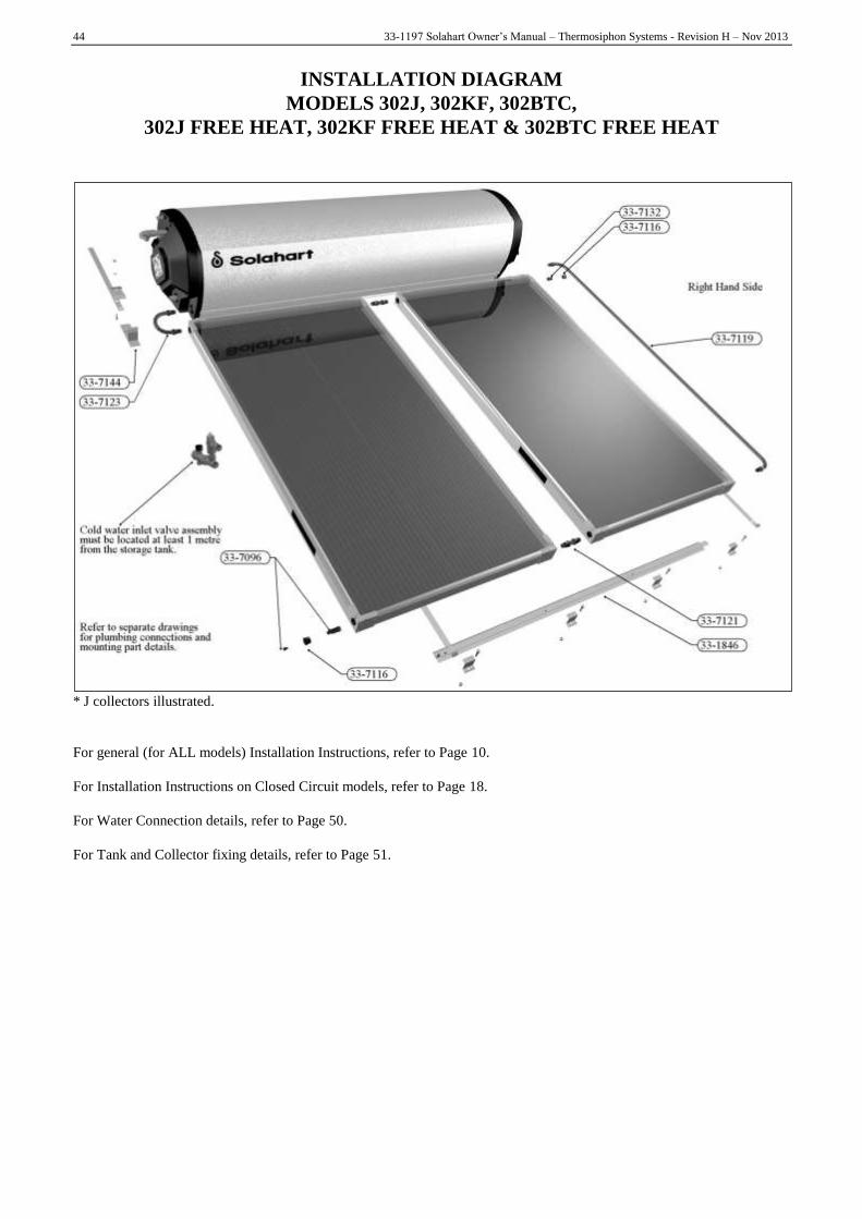
44 33-1197 Solahart Owner‟s Manual – Thermosiphon Systems - Revision H – Nov 2013
INSTALLATION DIAGRAM
MODELS 302J, 302KF, 302BTC,
302J FREE HEAT, 302KF FREE HEAT & 302BTC FREE HEAT
* J collectors illustrated.
For general (for ALL models) Installation Instructions, refer to Page 10.
For Installation Instructions on Closed Circuit models, refer to Page 18.
For Water Connection details, refer to Page 50.
For Tank and Collector fixing details, refer to Page 51.

33-1197 Solahart Owner‟s Manual – Thermosiphon Systems - Revision H – Nov 2013 45
INSTALLATION DIAGRAM
MODELS 302L & 302L FREE HEAT
For general (for ALL models) Installation Instructions, refer to Page 10.
For Installation Instructions on Open Circuit models, refer to Page 24.
For Water Connection details, refer to Page 50.
For Tank and Collector fixing details, refer to Page 51.
PLEASE NOTE
An Open Circuit system does not have freeze protection and is not suitable for installation in areas prone to freeze
conditions. This system has NO WARRANTY for freeze damage. In areas that are prone to frost / freezing or in bad water
areas, a Closed Circuit system should be used.

46 33-1197 Solahart Owner‟s Manual – Thermosiphon Systems - Revision H – Nov 2013
INSTALLATION DIAGRAM
MODELS 303J, 303KF,
303J FREE HEAT & 303KF FREE HEAT
* J collectors illustrated.
For general (for ALL models) Installation Instructions, refer to Page 10.
For Installation Instructions on Closed Circuit models, refer to Page 18.
For Water Connection details, refer to Page 50.
For Tank and Collector fixing details, refer to Page 51.

33-1197 Solahart Owner‟s Manual – Thermosiphon Systems - Revision H – Nov 2013 47
INSTALLATION DIAGRAM
MODELS 303L & 303L FREE HEAT
For general (for ALL models) Installation Instructions, refer to Page 10.
For Installation Instructions on Open Circuit models, refer to Page 24.
For Water Connection details, refer to Page 50.
For Tank and Collector fixing details, refer to Page 51.
PLEASE NOTE
An Open Circuit system does not have freeze protection and is not suitable for installation in areas prone to freeze
conditions. This system has NO WARRANTY for freeze damage. In areas that are prone to frost / freezing or in bad water
areas, a Closed Circuit system should be used.

48 33-1197 Solahart Owner‟s Manual – Thermosiphon Systems - Revision H – Nov 2013
INSTALLATION DIAGRAM
MODELS 443J, 443KF, 443BTC,
443J FREE HEAT, 443KF FREE HEAT & 443BTC FREE HEAT
* J collectors illustrated.
For general (for ALL models) Installation Instructions, refer to Page 10.
For Installation Instructions on Closed Circuit models, refer to Page 18.
For Water Connection details, refer to Page 50.
For Tank and Collector fixing details, refer to Page 51.

33-1197 Solahart Owner‟s Manual – Thermosiphon Systems - Revision H – Nov 2013 49
INSTALLATION DIAGRAM
MODELS 443L & 443L FREE HEAT
For general (for ALL models) Installation Instructions, refer to Page 10.
For Installation Instructions on Open Circuit models, refer to Page 24.
For Water Connection details, refer to Page 50.
For Tank and Collector fixing details, refer to Page 51.
PLEASE NOTE
An Open Circuit system does not have freeze protection and is not suitable for installation in areas prone to freeze
conditions. This system has NO WARRANTY for freeze damage. In areas that are prone to frost / freezing or in bad water
areas, a Closed Circuit system should be used.

50 33-1197 Solahart Owner‟s Manual – Thermosiphon Systems - Revision H – Nov 2013
CONNECTION DETAILS
Closed Circuit Systems Water Connections
(All Potable water & drain lines are ½” BSP)
Open Circuit Systems Water Connections
(All Potable water & drain lines are ½” BSP)

33-1197 Solahart Owner‟s Manual – Thermosiphon Systems - Revision H – Nov 2013 51
Assembly Drawings
HOOKING COLLECTOR / TANK STRAP TO COLLECTOR RAIL
1. If more than two solar collectors are installed, locate the additional collector rail(s) adjacent to the first collector rail
and join together using the drive cleat(s) supplied in the parts kit (refer to Detail B).
Note: The collector / tank straps are to be fitted to the collector rail(s) before fixing the straps to the rafters.
2. Determine which slots in the collector rail will be used for the collector / tank straps after locating the rafters and
taking note of the rafter spacing.
Recommended slots
Rafter
spacing
One collector
(1 x one
collector rail)
Two collectors
(1 x two
collector rail)
Three collectors
(1 x two and 1 x one
collector rails)
Four collectors
(1 x two and 2 x one
collector rails)
300 mm (12”) 1, 4 or 2, 3 1, 6 or 2, 5 1, 5 (long) & 3 (short) 2, 6 (long) & 3 (short-1) & 4 (short-2)
400 mm (16”) 1, 4 1, 5 or 2, 6 1, 5 (long) & 3 (short) 1, 5 (long) & 3 (short-1) & 4 (short-2)
450 mm (18”) 1, 4 2, 5 2, 5 (long) & 4 (short) 2, 5 (long) & 4 (short-1) & 3 (short-2)
500 mm (20”) 1, 4 1, 6 or 2, 5 1, 6 (long) & 4 (short) 1, 6 (long) & 4 (short-1) & 4 (short-2)
600 mm (24”) 2, 3 1, 5 or 2, 6 1, 5 (long) & 3 (short) 1, 5 (long) & 3 (short-1) & 4 (short-2)
900 mm (36”) 1, 4 2, 5 1, 4 (long) & 4 (short) 1, 4 (long) & 2 (short-1) & 4 (short-2)
collector rail – one collector
collector rail – two collectors
3. Noting the orientation of the collector strap‟s folded end, slide the long straight end of the collector strap through the
appropriate slot from the underside of the collector rail (refer to Detail A).
Pull the collector strap through until the first bend in the strap slips into the slot in the collector rail. The strap will
engage with the collector rail.
DETAIL A
BOTTOM COLLECTOR RAIL – COLLECTOR STRAP ORIENTATION

52 33-1197 Solahart Owner‟s Manual – Thermosiphon Systems - Revision H – Nov 2013
DETAIL B
BOTTOM COLLECTOR RAIL – COLLECTOR STRAP INSTALLATION
HOOKING COLLECTOR / TANK STRAP TO TANK CLAMP
1. The tank clamp (330872) is supplied as a single
extruded part and must be snapped into two. Snap by
bending the clamp on the groove location.
2. Noting the orientation of the collector / tank strap‟s
folded end, slide the short end of the strap through the
slot from the underside of the tank clamp.
3. Push the strap end through the tank clamp and make
sure it is correctly orientated as illustrated.
4. Loosely pre-assemble bolt, washer and nut as shown.
Ensure the bolt head fits into the valley of the tile or roof
sheet profile.
Tank Rail Fixing
Tank Clamp Assembly
20-4600

33-1197 Solahart Owner‟s Manual – Thermosiphon Systems - Revision H – Nov 2013 53
With Pitch Tiled Roof Mounting

54 33-1197 Solahart Owner‟s Manual – Thermosiphon Systems - Revision H – Nov 2013
INSTALLER’S CHECKLIST
Ensure that the system is installed as directed in this manual
Ensure the system is installed with the correct TILT (hot pipe side higher)
Check that all mechanical fixings are secured
Check that all pipe connections are correctly tightened
Ensure potable water is connected and switched on
Check that the potable water tank is filled
For Closed Circuit systems ensure the closed circuit has been commissioned correctly and is filled with the correct
concentration of Hartgard solution
Ensure that electrical power is switched on (if required)
Ensure the Collector covers are removed
Ensure that any pipe connections through the roof have been sealed correctly
In case of a remote installation make sure that a minimum of ¾” or 22mm pipe is used and that the piping has a
continuous upwards slope towards the tank.
Ensure roof tiles are put back in to position and roof flashing is watertight
Householder instructed on water heater system use
Provide this manual to the householder
SERVICING
To Empty The Water Heater
WARNING: THE POTABLE WATER SUPPLY TO THE SYSTEM SHOULD NOT BE SWITCHED OFF
UNTIL THE COLLECTORS ARE SECURELY COVERED BY AN OPAQUE MATERIAL.
1) For Closed Circuit Series, securely cover the collectors from sunlight with cardboard or other opaque material
BEFORE emptying the water heater.
2) Turn off the electricity supply.
3) Flush cold water through the tank to cool both the tank and the closed circuit fluid and turn off water supply.
4) For Closed Circuit Series, relieve the pressure in the jacket by removing the PR6 or PR200 jacket relief valve.
Extreme care should be taken when removing the valve as the jacket fluid could be at high temperature and under
pressure.
5) Release the water pressure at the pressure/temperature relief valve by holding the relief arm open.
6) Disconnect the cold water inlet and allow the water to drain out via a hose fitted to the cold water inlet connection.
7) Avoid contact with the hot water and ensure that the hose safely discharges hot water away from the roof area.
8) Hold open the tank relief lever to allow air into the storage tank.
9) For „L‟ Series only, unscrew and remove the bung plug on the bottom right-hand corner of the right-hand collector.
Note: If required, the tank can be flushed at this stage by removing the 6 bolt element flange and hosing out any sediment.
Anode Replacement
To replace the anode:
1) Turn off the electricity supply and water supply.
2) Release the water pressure at the pressure/temperature relief valve by holding the easing gear open.
3) Drain the cylinder to a level below the anode fitting (see “To Empty the Water Heater” below).
4) Remove the electrical cover.
5) Unscrew the anode nut located to the left of the electric element (or burner tube) and withdraw the old anode.
6) Insert the new anode assembly into the cylinder through the anode socket. Tighten the new anode nut.
7) Turn on the water supply, dispel air from the tank via a hot water tap or the pressure/temperature relief valve and
then check that the seal on the nut is watertight.
8) Re-fit the cover and turn on the electricity supply.
WARNING: DO NOT TURN POWER ON UNTIL THE WATER HEATER IS FILLED WITH WATER
OR DAMAGE TO THE HEATING ELEMENT WILL RESULT.
!
!

33-1197 Solahart Owner‟s Manual – Thermosiphon Systems - Revision H – Nov 2013 55
SOLAHART THERMOSIPHON
SOLAR WATER HEATER WARRANTY
1. THE SOLAHART WARRANTY – GENERAL
1.1 This warranty is given by Solahart Industries Pty Limited ABN 45 064 945 848 of 1 Alan Street, Rydalmere New South Wales.
1.2 Solahart offers national service through its Dealer network. Solahart will repair or replace components at the address of the water heater subject to the terms of the Solahart warranty. Solahart, in addition can provide preventative maintenance and advice on the operation of your water heater.
1.3 For details about this warranty, you can contact us on 1800 638 011 (Australia only). In other countries, contact your local Solahart Distributor.
1.4 The terms of this warranty and what is covered by it are set out in sections 2 and 3 and apply to water heaters manufactured after 1st January 2012.
1.5 If a subsequent version of this warranty is published, the terms of that warranty and what is covered by it will apply to water heaters manufactured after the date specified in the subsequent version.
2. TERMS OF THE SOLAHART WARRANTY AND EXCLUSIONS TO IT
2.1 The decision of whether to repair or replace a faulty component is at Solahart’s sole discretion.
2.2 If you require a call out and we find that the fault is not covered by the Solahart warranty, you are responsible for our standard call out charge. If you wish to have the relevant component repaired or replaced by Solahart, that service will be at your cost.
2.3 Where a failed component or cylinder is replaced under this warranty, the balance of the original warranty period will remain effective. The replacement does not carry a new Solahart warranty.
2.4 Where the water heater is installed outside the boundaries of a metropolitan area as defined by Solahart or further than 30 km from a regional Solahart Dealer, the cost of transport, insurance and travelling between the nearest Solahart Dealer’s premises and the installed site shall be the owner’s responsibility.
2.5 Where the water heater is installed in a position that does not allow safe or ready access, the cost of that access, including the cost of additional materials handling and/or safety equipment, shall be the owner’s responsibility. In other words, the cost of dismantling or removing cupboards, doors or walls and the cost of any special equipment to bring the water heater to floor or ground level or to a serviceable position is not covered by this warranty.
2.6 This warranty only applies to the original and genuine Solahart water heater in its original installed location and any genuine Solahart replacement parts.
2.7 The Solahart warranty does not cover faults that are a result of:
a) Accidental damage to the water heater or any component (for example: (i) Acts of God such as floods, storms, fires, lightning strikes and the like; and (ii) third party acts or omissions).
b) Misuse or abnormal use of the water heater.
c) Installation not in accordance with the Owner’s Guide and Installation Instructions or with relevant statutory and local requirements in the State or Territory in which the water heater is installed.
d) Connection at any time to a water supply that does not comply with the water supply guidelines as outlined in the Owner’s Guide and Installation Instructions.
e) Repairs, attempts to repair or modifications to the water heater by a person other than the Solahart Dealer or a Solahart Accredited Service Agent.
f) Faulty plumbing or faulty gas or power supply.
g) Failure to maintain the water heater in accordance with the Owner's Guide and Installation Instructions.
h) Transport damage.
i) Fair wear and tear from adverse conditions (for example, corrosion).
j) Cosmetic defects.
k) Breakage of collector glass for any reason including hail damage (we suggest that the collector glass be covered by your home insurance policy).
l) Ice formation in the waterways of a direct open circuit thermosiphon system or an indirect closed circuit thermosiphon system due to non Solahart approved or incorrectly mixed closed circuit fluid being used.
m) Non Solahart approved or incorrectly mixed closed circuit fluid being used or incorrect or insufficient filling of the closed circuit system with the closed circuit fluid.
2.8 Subject to any statutory provisions to the contrary, this warranty excludes any and all claims for damage to furniture, carpet, walls, foundations or any other consequential loss either directly or indirectly due to leakage from the water heater, or due to leakage from fittings and/ or pipe work of metal, plastic or other materials caused by water temperature, workmanship or other modes of failure.
2.9 The Solahart warranty applies to a Solahart thermosiphon solar water heater installed in either a “single-family domestic dwelling” or other than a “single-family domestic dwelling”.

56 33-1197 Solahart Owner‟s Manual – Thermosiphon Systems - Revision H – Nov 2013
SOLAHART THERMOSIPHON
SOLAR WATER HEATER WARRANTY
3. WHAT IS COVERED BY THE SOLAHART WARRANTY
FOR THE WATER HEATERS DETAILED IN THIS DOCUMENT
3.1 Solahart will repair or replace a faulty component of your water heater if it fails to operate in accordance with its specifications as follows:
What components are covered The period from the date of
installation in which the fault must appear in order to be covered
What coverage you receive
BT, J, KF, L, LC, LCS Systems (from date of installation)
All components (only if a tank, collector(s) and
components are purchased and installed as a complete new Solahart system)
Years 1 to 5 Repair and/or replacement of the faulty component, free of charge, including labour.
Free Heat Systems (from date of installation)
All components (only if a tank, collector(s) and
components are purchased and installed as a complete new Solahart system)
Years 1 to 5 Repair and/or replacement of the faulty component, free of charge, including labour.
The cylinder and solar collector(s) (only if a tank, collector(s) and
components are purchased and installed as a complete new Solahart system)
Years 6 to 10 Replacement cylinder or solar collector, free of charge. Installation and repair labour costs are the responsibility of the owner.
Individual Cylinder, Collector, Component (from date of installation)
All components Year 1 Repair and/or replacement of the faulty component, free of charge, including labour.
The cylinder and solar collector(s) (only if a tank, collector(s) and
components are purchased and installed as part of an existing Solahart system)
Years 2 to 5 Replacement cylinder or solar collector, free of charge. Installation and repair labour costs are the responsibility of the owner.
4. ENTITLEMENT TO MAKE A CLAIM UNDER THIS WARRANTY
4.1 To be entitled to make a claim under this warranty you need to:
a) Be the owner of the water heater or have consent of the owner to act on their behalf.
b) Contact Solahart without undue delay after detection of the defect and, in any event, within the applicable warranty period.
4.2 You are not entitled to make a claim under this warranty if your water heater:
a) Does not have its original serial numbers or rating labels.
5. HOW TO MAKE A CLAIM UNDER THIS WARRANTY
5.1 If you wish to make a claim under this warranty, you need to:
a) Contact Solahart on 1800 638 011 (Australia only) and provide owner’s details, address of the water heater, a contact number and date of installation of the water heater or if that’s unavailable, the date of manufacture and serial number (from the rating label on the water heater). In other countries, contact your local Solahart Distributor.
b) Solahart will arrange for the water heater to be tested and assessed on-site.
c) If Solahart determines that you have a valid warranty claim, Solahart will repair or replace the water heater in accordance with this warranty.
5.2 Any expenses incurred in the making of a claim under this warranty will be borne by you.
6. THE AUSTRALIAN CONSUMER LAW
6.1 In Australia, our goods come with guarantees that cannot be excluded under the Australian Consumer Law. You are entitled to a replacement or refund for a major failure and for compensation for any other reasonably foreseeable loss or damage. You are also entitled to have the goods repaired or replaced if the goods fail to be of acceptable quality and the failure does not amount to a major failure.
6.2 The Solahart warranty (set out above) is in addition to any rights and remedies that you may have under the Australian Consumer Law.

AFFIX INSTALLATION AND WARRANTY REPORT HERE
Note: Installation and Warranty report to be produced in quadruplicate
on carbon copy paper in the colours indicated

Solahart Industries Pty Ltd (ABN 45 064 945 848) Principal Manufacturing Facility 112 Pilbara St Welshpool, Western Australia, 6106 Australia
International Sales
Telephone International Sales:
+ 61 8 9351 4600
Facsimile International Sales:
+ 61 8 9351 4698
Email:
Web:
www.solahart.com
Postal Address: PO Box 95 Welshpool WA 6986 Australia
International Offices
www.solahart.com.au Registered Office 1 Alan Street (PO Box 6) Rydalmere New South Wales 2116 Australia
Europe
Phone International: + 31 492 579 696
Facsimile International: + 31 492 579 694
USA
Australia Phone International: + 1 800 621 5622
For SERVICE Telephone - 1800 638 011 or your nearest Solahart Dealer
Facsimile International: + 1 334 260 4672
For Sales Telephone - 1300 769 475 or your nearest Solahart Dealer
Item No 331197 Rev H
2013 November