Embed Size (px)
Citation preview
SOIS P&P Concepts &
Mapping of the Device Discovery service onto the MIL-STD-1553
Massimiliano Ciccone
ESA/ESTEC
02-Oct-2007 (CCSDS-Darmstadt)
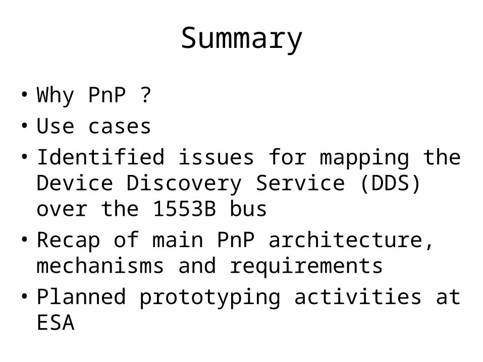
Summary
• Why PnP ?
• Use cases
• Identified issues for mapping the Device Discovery Service (DDS) over the 1553B bus
• Recap of main PnP architecture, mechanisms and requirements
• Planned prototyping activities at ESA

Why PnP ?
- A spacecraft could be built using ready-to-integrate components that can be assembled together with minimal human intervention
- Higher reliability of Spacecraft by eliminating SW/HW configuration error
- Increased robustness due to hot-swappable components to be used in case of failure of nominal ones.
- Easier and more flexible AIT process thanks to self-configuring flight systems
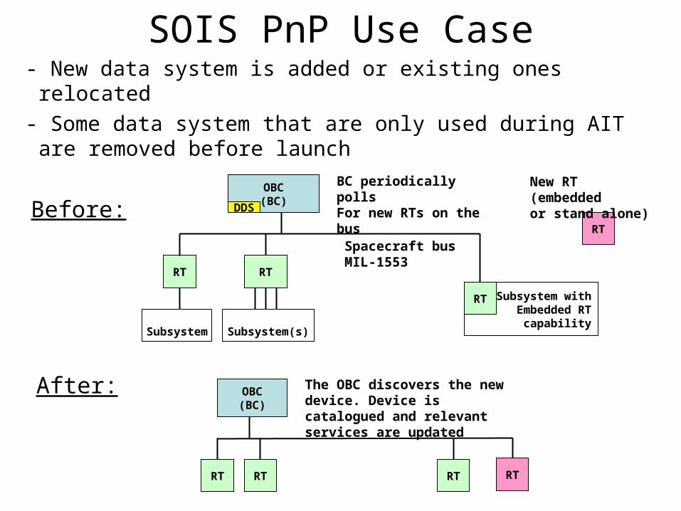
SOIS PnP Use Case- New data system is added or existing ones relocated
- Some data system that are only used during AIT are removed before launch
OBC(BC)
RT
Spacecraft busMIL-1553
Before:
After:
BC periodically polls For new RTs on the bus
RT
RT
OBC(BC)
RT
The OBC discovers the new device. Device is catalogued and relevant services are updated
RT RT
New RT (embeddedor stand alone)
RT
Subsystem Subsystem(s)
Subsystem withEmbedded RT
capability
RT
DDS
1553 Terminology
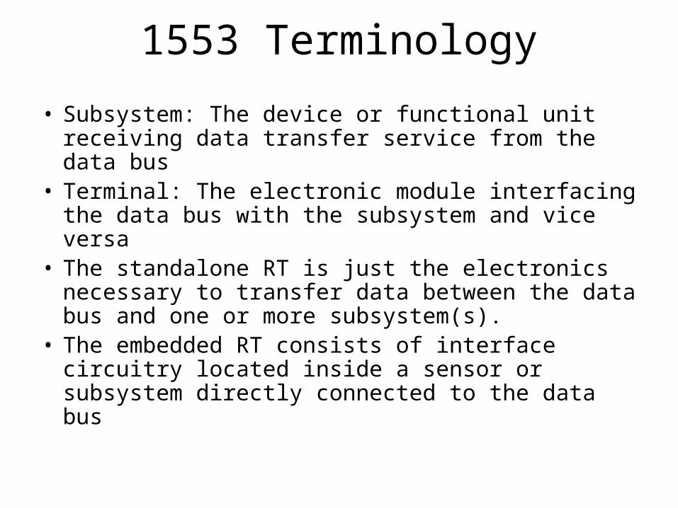
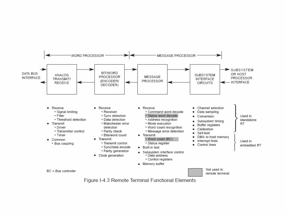
• Subsystem: The device or functional unit receiving data transfer service from the data bus
• Terminal: The electronic module interfacing the data bus with the subsystem and vice versa
• The standalone RT is just the electronics necessary to transfer data between the data bus and one or more subsystem(s).
• The embedded RT consists of interface circuitry located inside a sensor or subsystem directly connected to the data bus
PnP Prerequisites
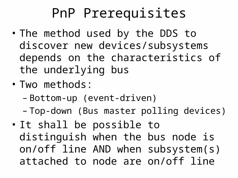
• The method used by the DDS to discover new devices/subsystems depends on the characteristics of the underlying bus
• Two methods:– Bottom-up (event-driven)– Top-down (Bus master polling devices)
• It shall be possible to distinguish when the bus node is on/off line AND when subsystem(s) attached to node are on/off line
DDS Issues
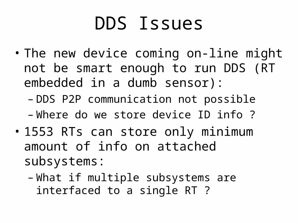
• The new device coming on-line might not be smart enough to run DDS (RT embedded in a dumb sensor):– DDS P2P communication not possible– Where do we store device ID info ?
• 1553 RTs can store only minimum amount of info on attached subsystems:– What if multiple subsystems are interfaced to a
single RT ?

RT Interfacing multiple Subsystems

Mapping DDS onto 1553• In 1553 BC is the sole source of communication
(cmd/response method); therefore the DDS must adopt the top-down approach
• On the 1553 bus the device discovery mechanism has to be centralized; that is the BC must poll for new devices attached on the bus
• The BC sends messages to a RT by mean of a command word
• The receiving terminal validates error free msg reception by transmitting a status word with info on its health

Mapping DDS onto 1553
Mapping DDS onto 1553
For a terminal to be considered operational, it has to:
•Be powered up
•Start and complete its internal self-test (Standalone RT only)
•The system attached to the RT needs to be initialized by the BC with aperiodic
operations. Then, if necessary, the BC can begin periodic message communication with the new RT in the loop
Mapping DDS onto 1553
Sequence of mode codes cmds:
• Transmit Status Word (Discovers the new RT)• Initiate Self Test : initiates built-in-test (BIT)
circuitry within a remote terminal (Completed within 100 milliseconds)
• Transmit BIT Word: yields the results of the BIT

Mapping DDS onto 1553
• The BC shall poll the all RT address range (0-30) with a ‘Transmit Status’ mode cmd
• This cmd shall cause the RT to transmit the status word associated with the last valid cmd
• A new RT coming on-line is detected by receipt of status word from the polled terminal
• The failure or off-line status of a RT is detected by the lack of status word transmission from the terminal upon polling
• But this only discovers new nodes on the bus, does not discover the attached subsystem(s)…
Mapping DDS onto 1553
•A unique standard transmit terminal sub-address must be selected to provide profile of attached subsystem(s) (Electronic Data Sheet)
•Some kind of intelligence needed at RT side to update info on attached subsytem(s)
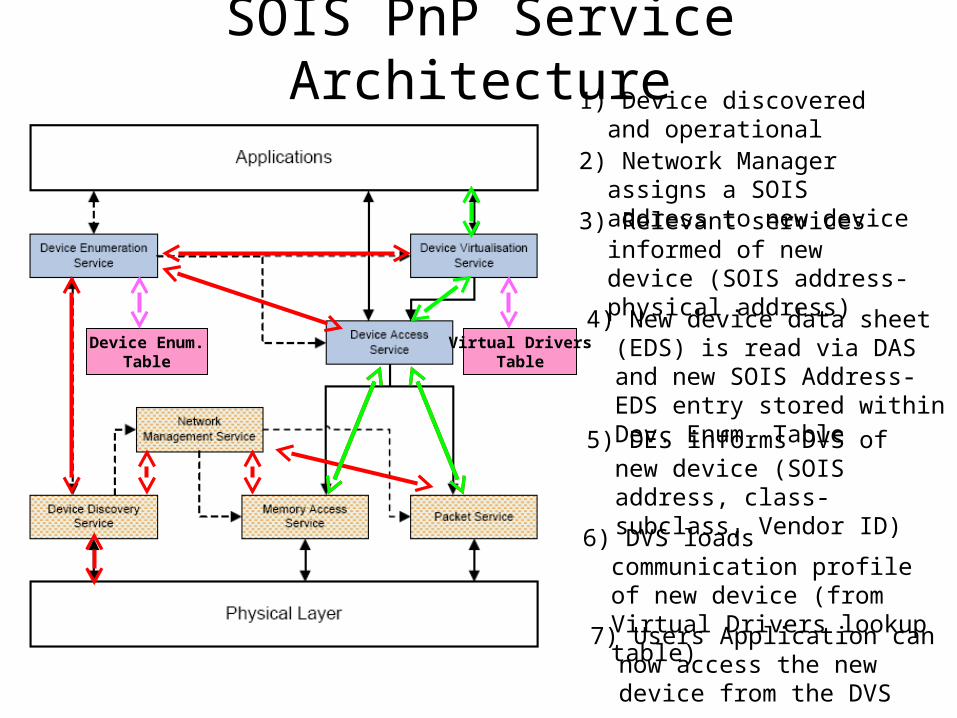
SOIS PnP Service Architecture1) Device discovered and
operational
3) Relevant services informed of new device (SOIS address-physical address)
4) New device data sheet (EDS) is read via DAS and new SOIS Address-EDS entry stored within Dev. Enum. Table
5) DES informs DVS of new device (SOIS address, class-subclass, Vendor ID)
7) Users Application can now access the new device from the DVS
Device Enum.Table
2) Network Manager assigns a SOIS address to new device
6) DVS loads communication profile of new device (from Virtual Drivers lookup table)
Virtual DriversTable
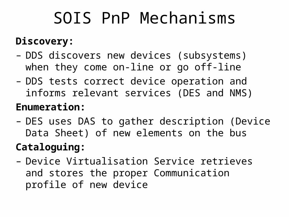
SOIS PnP Mechanisms
Discovery:– DDS discovers new devices (subsystems) when
they come on-line or go off-line– DDS tests correct device operation and informs
relevant services (DES and NMS)
Enumeration:– DES uses DAS to gather description (Device
Data Sheet) of new elements on the bus
Cataloguing:– Device Virtualisation Service retrieves and stores
the proper Communication profile of new device
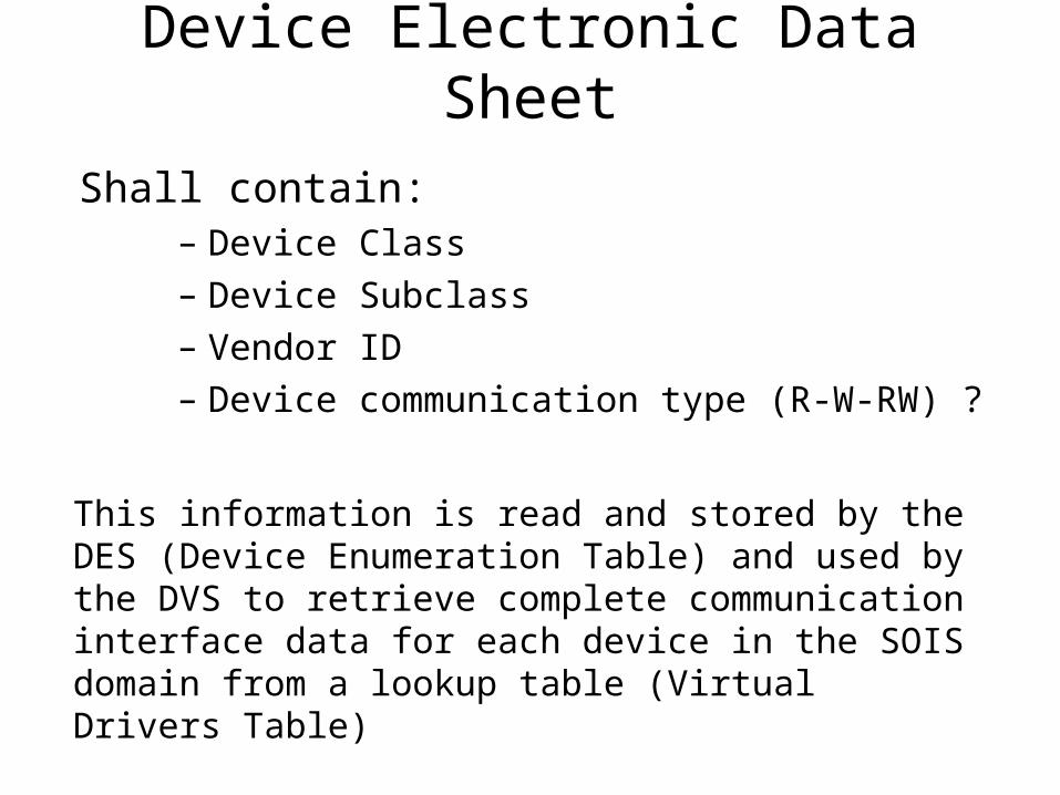
Device Electronic Data Sheet
Shall contain:– Device Class
– Device Subclass
– Vendor ID
– Device communication type (R-W-RW) ?
This information is read and stored by the DES (Device Enumeration Table) and used by the DVS to retrieve complete communication interface data for each device in the SOIS domain from a lookup table (Virtual Drivers Table)
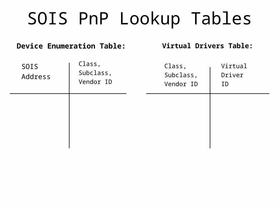
SOIS PnP Lookup Tables
Device Enumeration Table: Virtual Drivers Table:
Class,
Subclass,
Vendor ID
SOIS
Address
Class,
Subclass,
Vendor ID
Virtual
Driver
ID

Identified issues• The PnP-1553B polling process should not be
invasive. That is it shall not affect the real-time constraints of the OBSW
• The DDS user must have a mean to start/stop the polling of devices and to set up polling frequency (MIB values or primitives ?)
• The DAS shall have a Read_EDS primitive request
• Agree on standard 1553 RT sub-address for reading device profile
• Agree on standard set of 1553 mode codes for device discovery
• Define a common SOIS format for device EDS
ESA Prototyping Activities
• SOIS PnP will be prototyped at ESTEC over the RASTA reference facility with DDS adaptation over 1553B and Spacewire busses

Backup
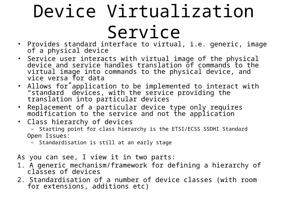
Device Virtualization Service• Provides standard interface to virtual, i.e. generic, image of a physical
device • Service user interacts with virtual image of the physical device and service
handles translation of commands to the virtual image into commands to the physical device, and vice versa for data
• Allows for application to be implemented to interact with “standard” devices, with the service providing the translation into particular devices
• Replacement of a particular device type only requires modification to the service and not the application
• Class hierarchy of devices – Starting point for class hierarchy is the ETSI/ECSS SSDHI Standard
Open Issues: – Standardisation is still at an early stage
As you can see, I view it in two parts:1. A generic mechanism/framework for defining a hierarchy of classes of
devices2. Standardisation of a number of device classes (with room for extensions,
additions etc)
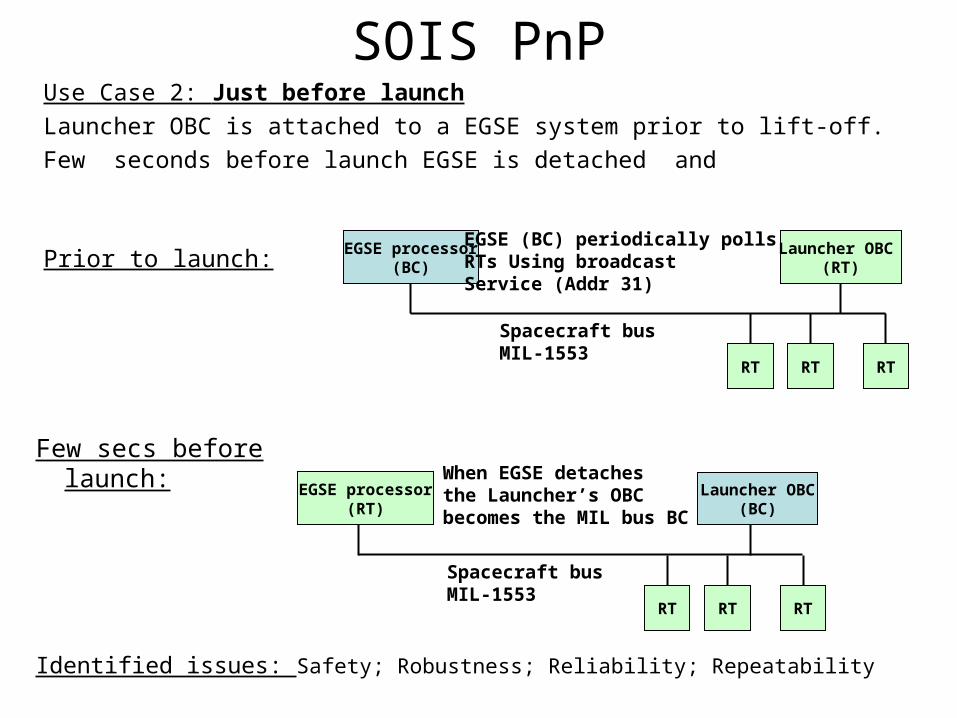
SOIS PnPUse Case 2: Just before launch
Launcher OBC is attached to a EGSE system prior to lift-off.
Few seconds before launch EGSE is detached and
EGSE processor(BC)
RT
Spacecraft busMIL-1553
Prior to launch:
Few secs before launch:
EGSE (BC) periodically polls RTs Using broadcast Service (Addr 31)
RT RT
Launcher OBC (RT)
Spacecraft busMIL-1553
When EGSE detaches the Launcher’s OBC becomes the MIL bus BC
RT RT RT
Launcher OBC(BC)
Identified issues: Safety; Robustness; Reliability; Repeatability
EGSE processor(RT)
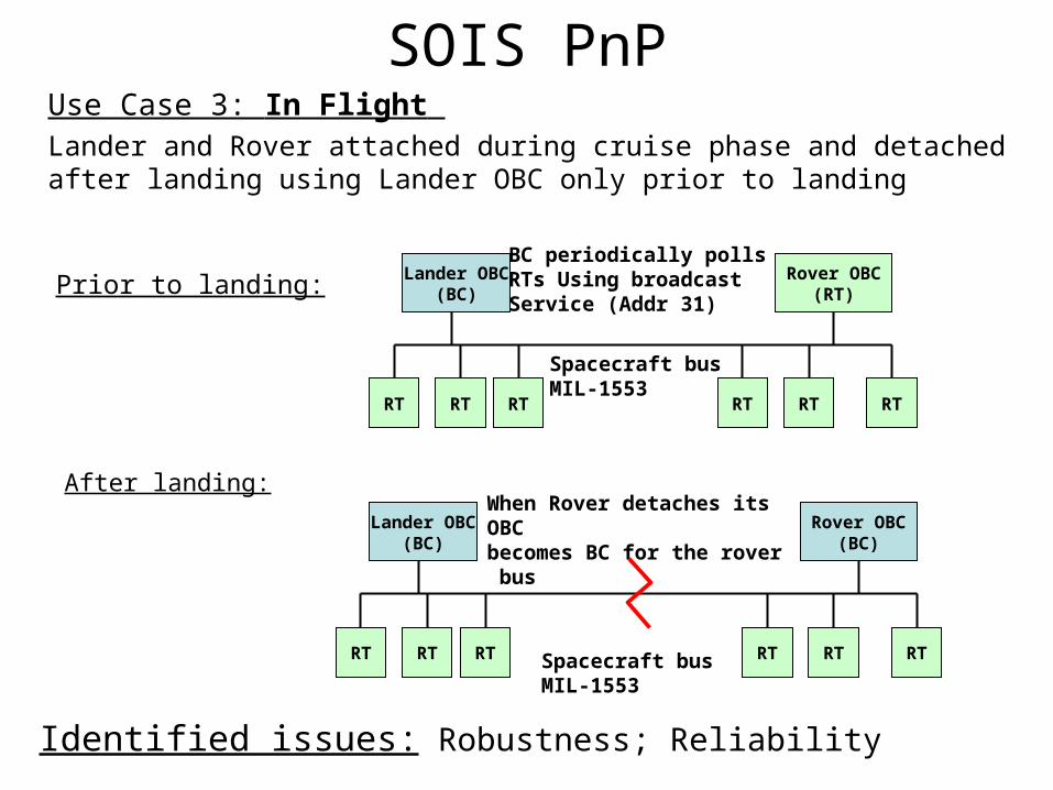
SOIS PnPUse Case 3: In Flight Lander and Rover attached during cruise phase and detached after landing using Lander OBC only prior to landing
Lander OBC(BC)
RT
Spacecraft busMIL-1553
Prior to landing:
After landing:
BC periodically polls RTs Using broadcast Service (Addr 31)
RT RT RT RT RT
Rover OBC(RT)
Lander OBC(BC)
RT Spacecraft busMIL-1553
When Rover detaches its OBC becomes BC for the rover bus
RT RT RT RT RT
Rover OBC(BC)
Identified issues: Robustness; Reliability
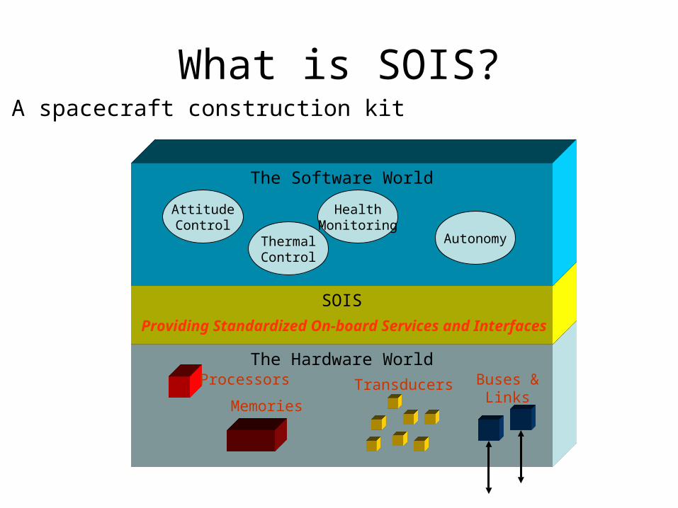
The Hardware World
SOIS
What is SOIS?
TransducersProcessors
Memories
Buses &Links
The Software World
AttitudeControl
ThermalControl
HealthMonitoring
Autonomy
Providing Standardized On-board Services and Interfaces
A spacecraft construction kit