Embed Size (px)
Citation preview

Bioretention Cells
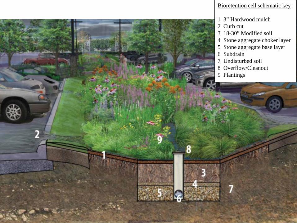
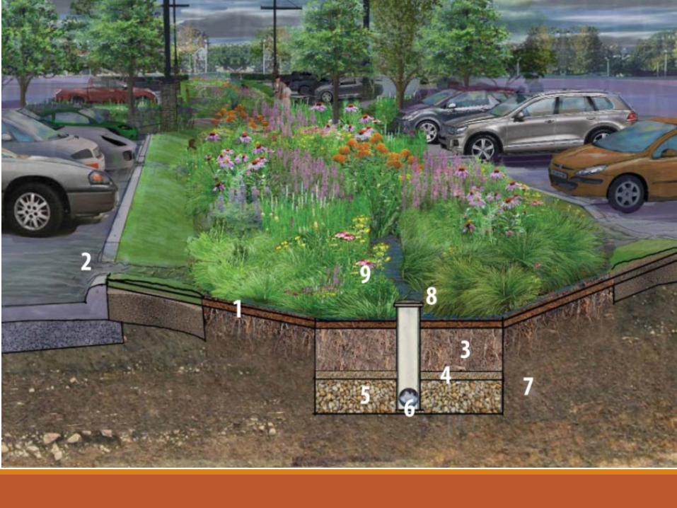
Bioretention cell schematic key
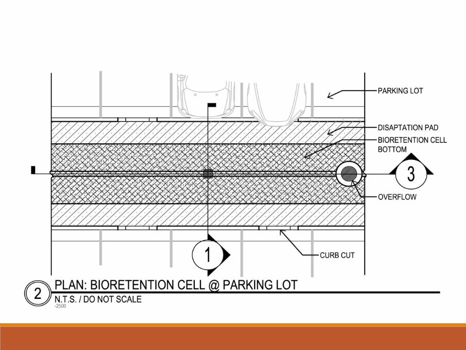
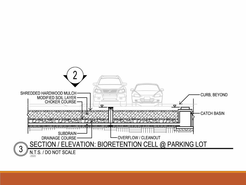
1 3” Hardwood mulch2 Curb cut3 18-30” Modified soil4 Stone aggregate choker layer5 Stone aggregate base layer6 Subdrain7 Undisturbed soil8 Overflow/Cleanout9 Plantings
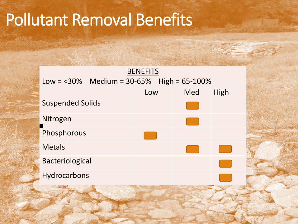
Pollutant Removal Benefits
BENEFITSLow = <30% Medium = 30-65% High = 65-100%
Low Med HighSuspended Solids
Nitrogen
Phosphorous
Metals
Bacteriological
Hydrocarbons
Bioretention
Incorporate shallow landscaped level depressions that temporarily store and readily infiltrate runoff.
Includes:
• Bioretention Cells• Stormwater Planters• Tree Filters • Rain Gardens and• Enhanced Rain Gardens
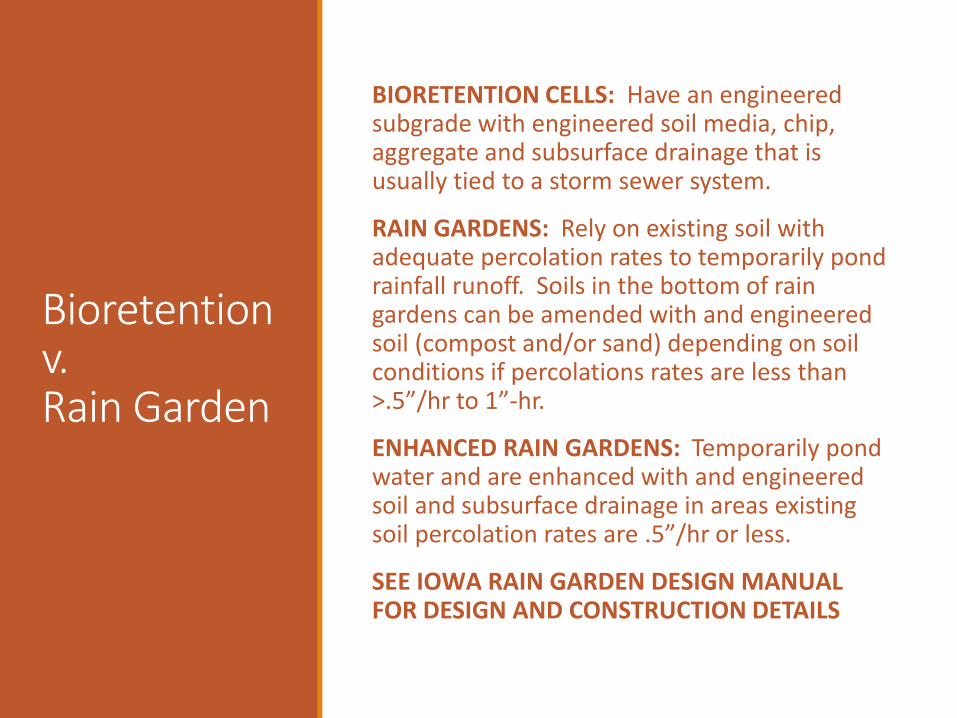
Bioretention v.Rain Garden
BIORETENTION CELLS: Have an engineered subgrade with engineered soil media, chip, aggregate and subsurface drainage that is usually tied to a storm sewer system.
RAIN GARDENS: Rely on existing soil with adequate percolation rates to temporarily pond rainfall runoff. Soils in the bottom of rain gardens can be amended with and engineered soil (compost and/or sand) depending on soil conditions if percolations rates are less than >.5”/hr to 1”-hr.
ENHANCED RAIN GARDENS: Temporarily pond water and are enhanced with and engineered soil and subsurface drainage in areas existing soil percolation rates are .5”/hr or less.
SEE IOWA RAIN GARDEN DESIGN MANUAL FOR DESIGN AND CONSTRUCTION DETAILS
Bioretention
Manages water quality runoff volume from residential, commercial, and institutional sites.
Drainage area for each cell is typically 0.5 to 2.0 acres.
Larger drainage areas should be divided into smaller sub-areas with individual bioretention cells distributed throughout the site.
Suitable for landscaped depressional areas such as parking lot islands, road medians, and street right-of-ways.
Typical Uses
Bioretention
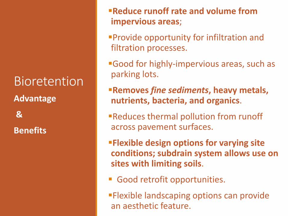
Reduce runoff rate and volume from impervious areas;
Provide opportunity for infiltration and filtration processes.
Good for highly-impervious areas, such as parking lots.
Removes fine sediments, heavy metals, nutrients, bacteria, and organics.
Reduces thermal pollution from runoff across pavement surfaces.
Flexible design options for varying site conditions; subdrain system allows use on sites with limiting soils.
Good retrofit opportunities.
Flexible landscaping options can provide an aesthetic feature.
Advantage
&
Benefits
BioretentionHigh entrance velocities and concentrated flows may need special design considerations.
High sediment loads can cause premature failure; upstream [pretreatment] practice is needed.
High water table may require special design considerations
Disadvantages
&
Limitations
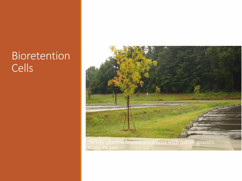
BioretentionCells
Newly planted bioretention area with native grasses. Source: Pat Sauer
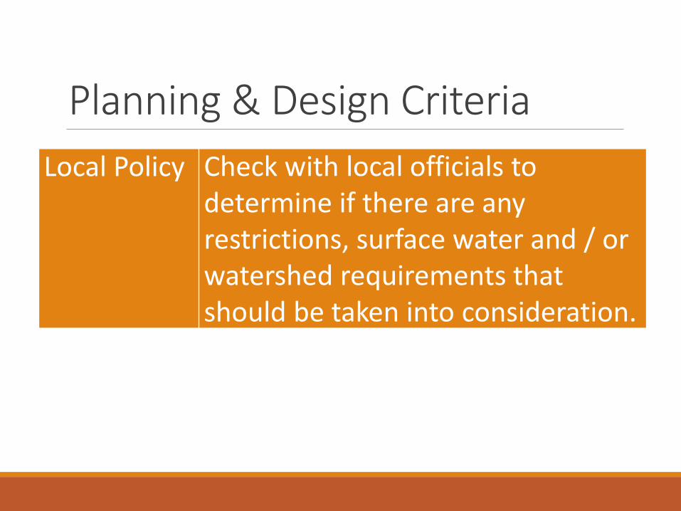
Local Policy Check with local officials to determine if there are any restrictions, surface water and / or watershed requirements thatshould be taken into consideration.
Planning & Design Criteria
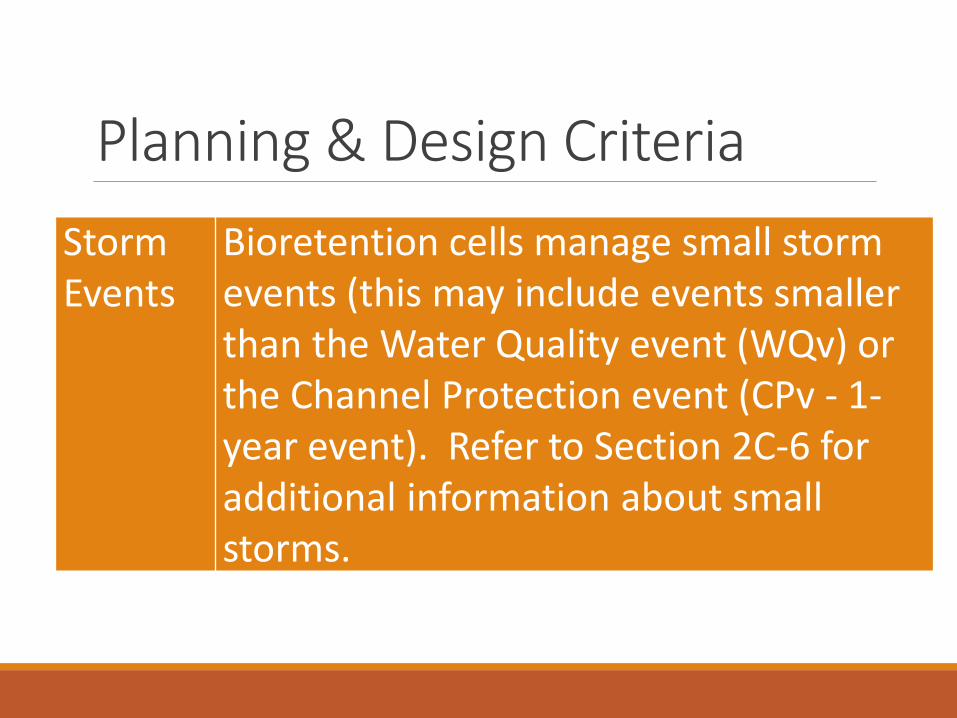
Planning & Design CriteriaStorm Events
Bioretention cells manage small storm events (this may include events smaller than the Water Quality event (WQv) or the Channel Protection event (CPv - 1-year event). Refer to Section 2C-6 for additional information about small storms.
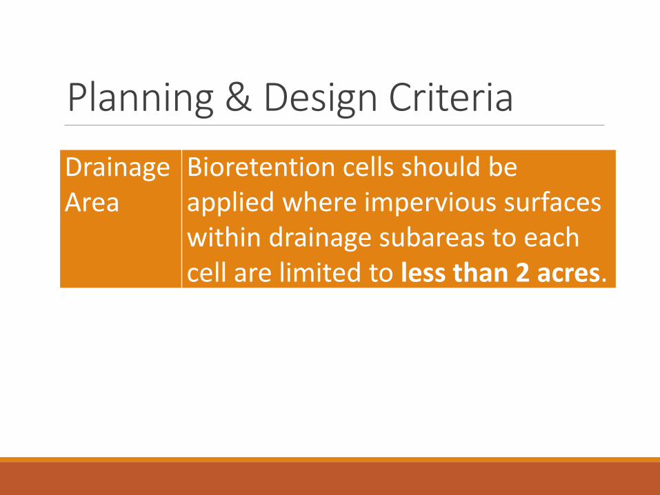
Planning & Design CriteriaDrainage Area
Bioretention cells should be applied where impervious surfaces within drainage subareas to each cell are limited to less than 2 acres.
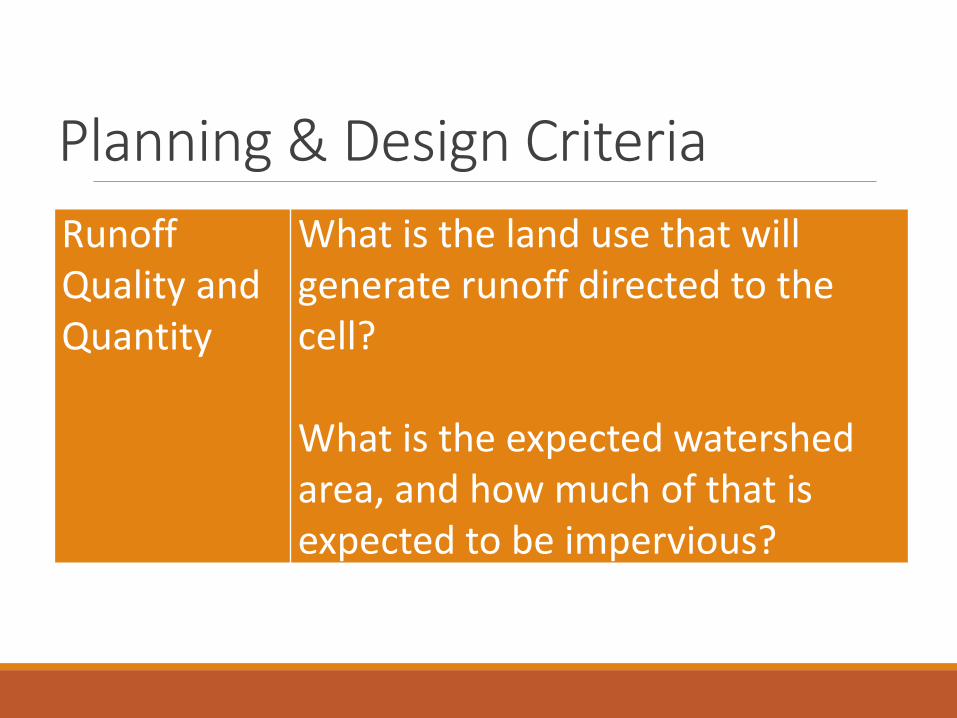
Planning & Design CriteriaRunoffQuality and Quantity
What is the land use that will generate runoff directed to the cell?
What is the expected watershed area, and how much of that is expected to be impervious?
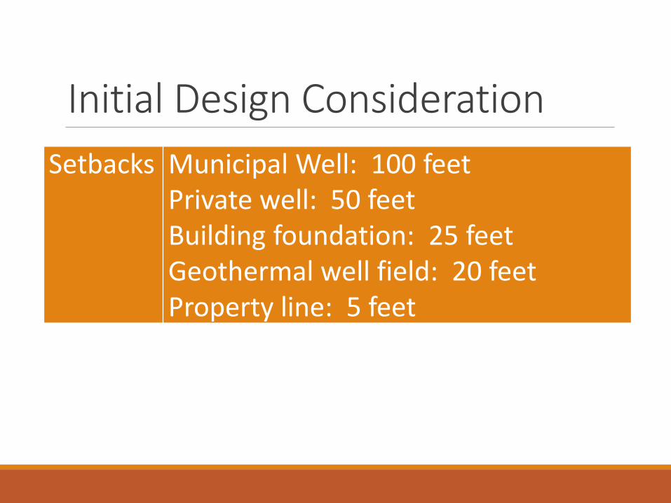
Initial Design ConsiderationSetbacks Municipal Well: 100 feet
Private well: 50 feetBuilding foundation: 25 feetGeothermal well field: 20 feetProperty line: 5 feet
Planning & Design CriteriaLocation –Source
Bioretention cells should be placed close to the source of runoff.
Location -Groundwater
The bottom of the aggregate layer should have 2 feet of vertical separation from expected high groundwater elevations or bedrock layers.
Planning & Design Criteria
Planning & Design CriteriaLocation -Inlet
Elevations must be carefully worked out to ensure that the desired runoff flow enters the facility.
Planning & Design CriteriaDecentralizedPractices
Several smaller bioretention cells can treat more manageable amounts of runoff closer to its source. Use site grading to divert runoff to smaller depressions in open spaces such as parking islands, landscaped areas, etc.
Planning & Design CriteriaOn-line Systems
A cell is considered on-line if all runoff from the upstream area enters the practice.
Planning & Design CriteriaOn-Site Integration
Stormwater management site integration is a preferred alternative to end-of-pipe BMP design, where feasible.
Planning & Design CriteriaOn-Line Systems
May offer possibility to attenuate or detain flows from CPv - need to prevent:• Erosive flow velocities near inlets / outlets• Deep ponding could compact soil layers• Extended drawdown periods affecting
existing plants

Planning & Design CriteriaOn-Line Systems
May offer possibility to attenuate or detain flows from CPv - need to prevent:• Erosive flow velocities near inlets / outlets• Deep ponding could compact soil layers• Extended drawdown periods affecting
existing plants

Planning & Design CriteriaOff-line Systems
Off-line systems employ a diversion structure to divert the first flush of flow to the treatment practice.
Planning & Design CriteriaOff-line Systems
Larger flows are diverted to controls downstream (see Section 2F-1, F for more discussion of off-line systems and design guidance for diversion structures and flow splitters).
Planning & Design CriteriaIntermittent Flow
Bioretention cells are designed for intermittent flow and must be allowed to drain and dry outbetween rainfall events.
Planning & Design CriteriaEarlyplanning and Aesthetics
Bioretention cell locations should be integrated into the site planning process, and aesthetic considerations should be taken into account in their siting and design.
Preliminary InvestigationDrainage Area TributarySpace RequiredSlopeMinimum HeadWater TableExisting Site Soils
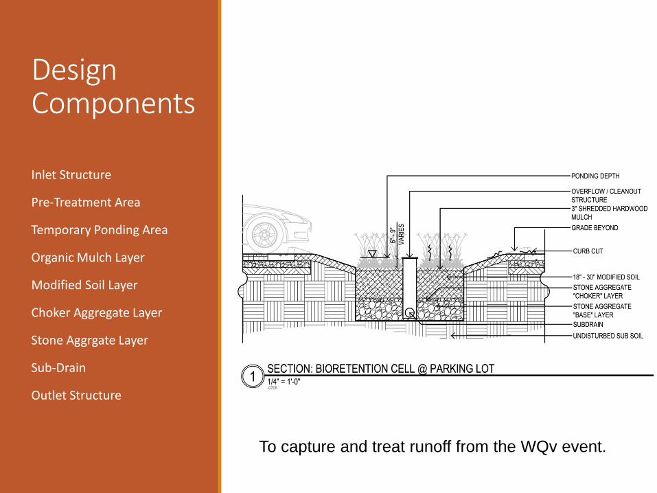
Design Components
Inlet Structure
Pre-Treatment Area
Temporary Ponding Area
Organic Mulch Layer
Modified Soil Layer
Choker Aggregate Layer
Stone Aggrgate Layer
Sub-Drain
Outlet Structure
To capture and treat runoff from the WQv event.
After the designer has completed preliminaryinvestigations, and understands the designcomponents of a bioretention cell.
Bioretention Cell Sizing and Design Calculations.
Biocell Design
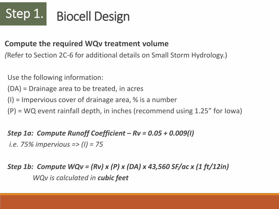
Compute the required WQv treatment volume (Refer to Section 2C-6 for additional details on Small Storm Hydrology.)
Use the following information:(DA) = Drainage area to be treated, in acres(I) = Impervious cover of drainage area, % is a number(P) = WQ event rainfall depth, in inches (recommend using 1.25” for Iowa)
Step 1a: Compute Runoff Coefficient – Rv = 0.05 + 0.009(I)i.e. 75% impervious => (I) = 75
Step 1b: Compute WQv = (Rv) x (P) x (DA) x 43,560 SF/ac x (1 ft/12in)WQv is calculated in cubic feet
Step 1.
Biocell Design
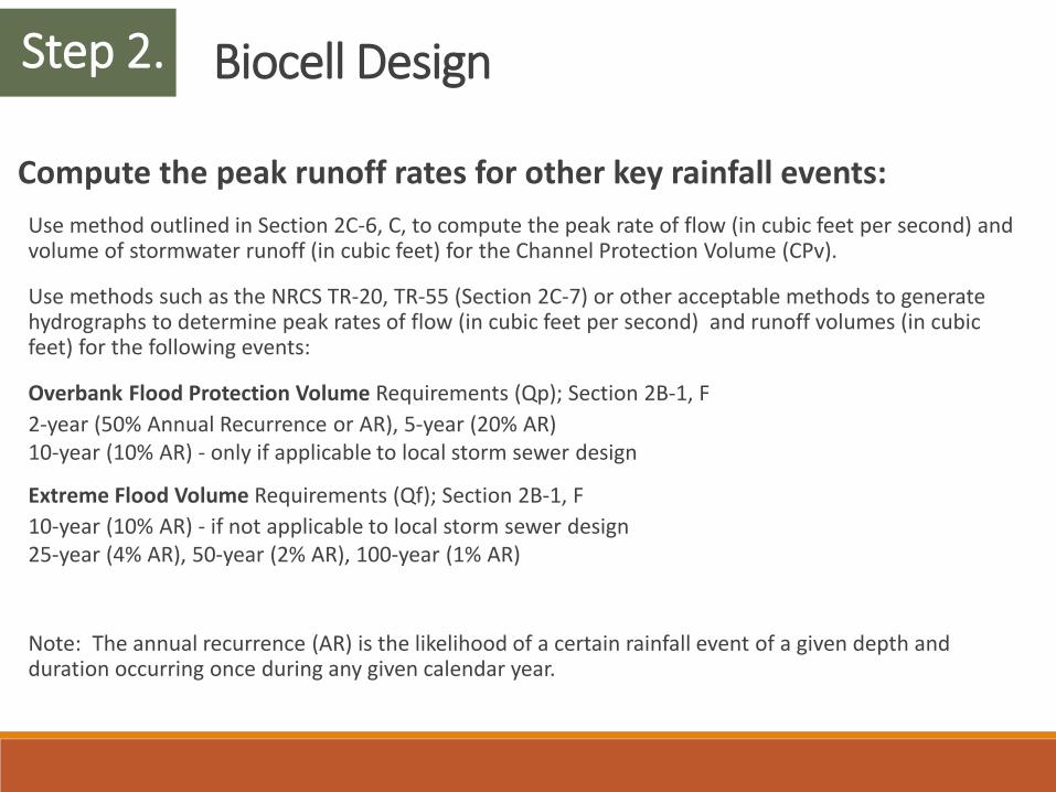
Compute the peak runoff rates for other key rainfall events:Use method outlined in Section 2C-6, C, to compute the peak rate of flow (in cubic feet per second) and volume of stormwater runoff (in cubic feet) for the Channel Protection Volume (CPv).
Use methods such as the NRCS TR-20, TR-55 (Section 2C-7) or other acceptable methods to generate hydrographs to determine peak rates of flow (in cubic feet per second) and runoff volumes (in cubic feet) for the following events:
Overbank Flood Protection Volume Requirements (Qp); Section 2B-1, F2-year (50% Annual Recurrence or AR), 5-year (20% AR)10-year (10% AR) - only if applicable to local storm sewer design
Extreme Flood Volume Requirements (Qf); Section 2B-1, F10-year (10% AR) - if not applicable to local storm sewer design25-year (4% AR), 50-year (2% AR), 100-year (1% AR)
Note: The annual recurrence (AR) is the likelihood of a certain rainfall event of a given depth and duration occurring once during any given calendar year.
Step 2.
Biocell Design
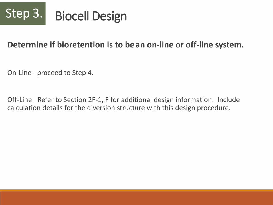
Determine if bioretention is to be an on-line or off-line system.
On-Line - proceed to Step 4.
Off-Line: Refer to Section 2F-1, F for additional design information. Include calculation details for the diversion structure with this design procedure.
Step 3.
Biocell Design
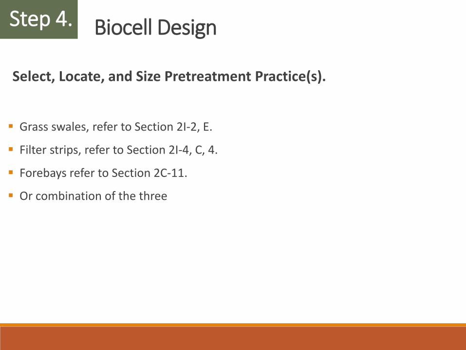
Select, Locate, and Size Pretreatment Practice(s).
Grass swales, refer to Section 2I-2, E.
Filter strips, refer to Section 2I-4, C, 4.
Forebays refer to Section 2C-11.
Or combination of the three
Step 4.
Biocell Design
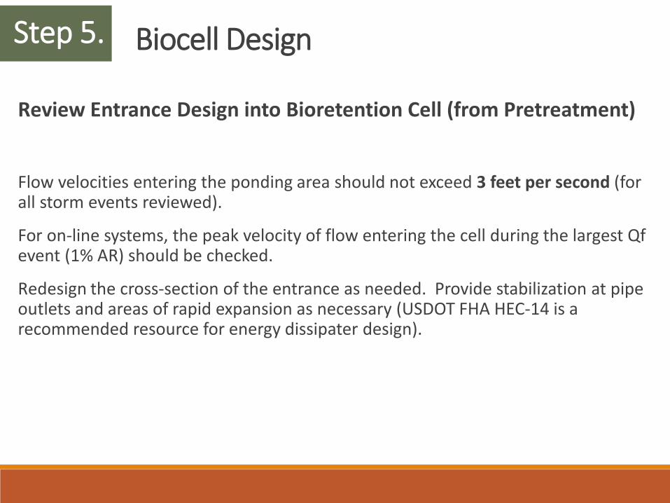
Review Entrance Design into Bioretention Cell (from Pretreatment)
Flow velocities entering the ponding area should not exceed 3 feet per second (for all storm events reviewed).
For on-line systems, the peak velocity of flow entering the cell during the largest Qfevent (1% AR) should be checked.
Redesign the cross-section of the entrance as needed. Provide stabilization at pipe outlets and areas of rapid expansion as necessary (USDOT FHA HEC-14 is a recommended resource for energy dissipater design).
Step 5.
Biocell Design
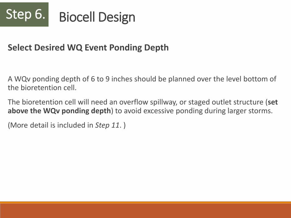
Select Desired WQ Event Ponding Depth
A WQv ponding depth of 6 to 9 inches should be planned over the level bottom of the bioretention cell.
The bioretention cell will need an overflow spillway, or staged outlet structure (set above the WQv ponding depth) to avoid excessive ponding during larger storms.
(More detail is included in Step 11. )
Step 6.
Biocell Design
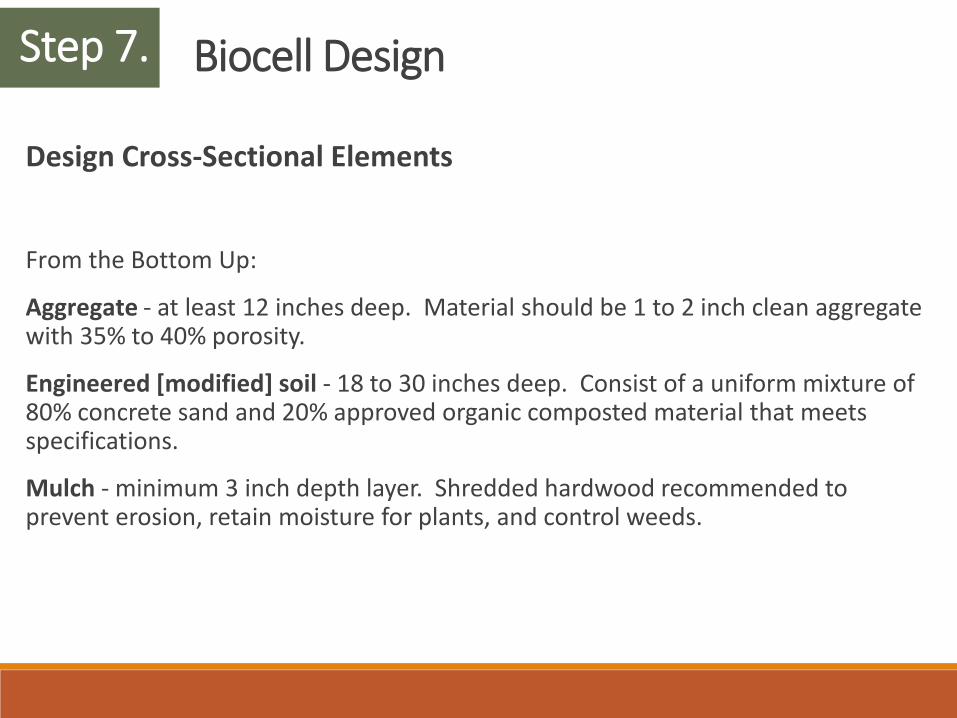
Design Cross-Sectional Elements
From the Bottom Up:
Aggregate - at least 12 inches deep. Material should be 1 to 2 inch clean aggregate with 35% to 40% porosity.
Engineered [modified] soil - 18 to 30 inches deep. Consist of a uniform mixture of 80% concrete sand and 20% approved organic composted material that meets specifications.
Mulch - minimum 3 inch depth layer. Shredded hardwood recommended to prevent erosion, retain moisture for plants, and control weeds.
Step 7.
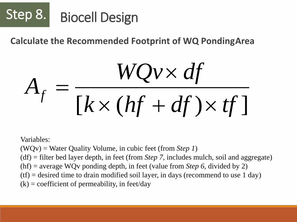
Biocell DesignCalculate the Recommended Footprint of WQ Ponding Area
Step 8.
])([ tfdfhfkdfWQvAf ×+×
×=
Variables:(WQv) = Water Quality Volume, in cubic feet (from Step 1)(df) = filter bed layer depth, in feet (from Step 7, includes mulch, soil and aggregate)(hf) = average WQv ponding depth, in feet (value from Step 6, divided by 2)(tf) = desired time to drain modified soil layer, in days (recommend to use 1 day)(k) = coefficient of permeability, in feet/day
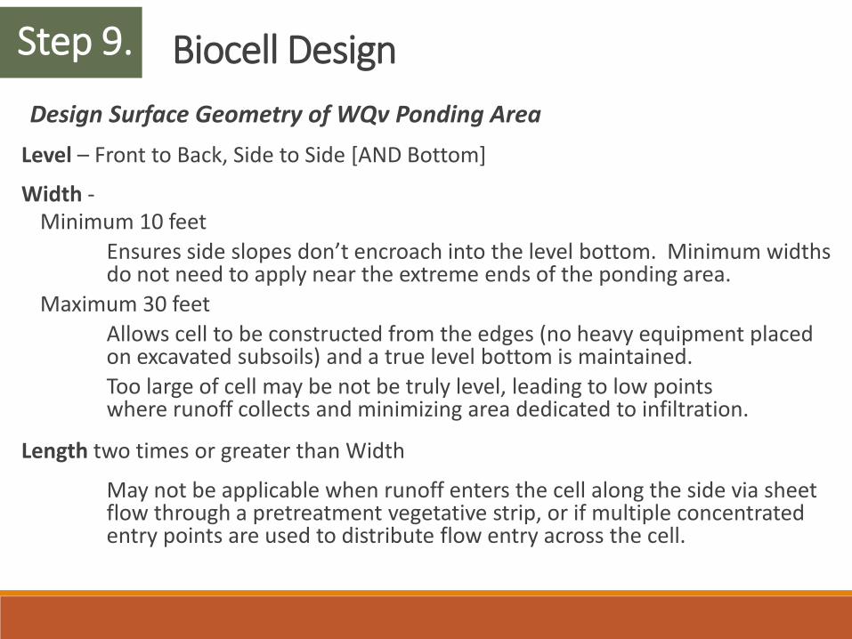
Biocell DesignDesign Surface Geometry of WQv Ponding Area
Level – Front to Back, Side to Side [AND Bottom]
Width -Minimum 10 feet
Ensures side slopes don’t encroach into the level bottom. Minimum widths do not need to apply near the extreme ends of the ponding area.
Maximum 30 feetAllows cell to be constructed from the edges (no heavy equipment placed on excavated subsoils) and a true level bottom is maintained. Too large of cell may be not be truly level, leading to low points where runoff collects and minimizing area dedicated to infiltration.
Length two times or greater than Width
May not be applicable when runoff enters the cell along the side via sheet flow through a pretreatment vegetative strip, or if multiple concentrated entry points are used to distribute flow entry across the cell.
Step 9.
Biocell Design
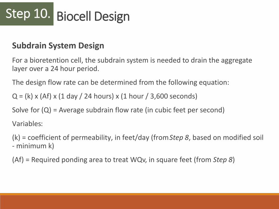
Subdrain System DesignFor a bioretention cell, the subdrain system is needed to drain the aggregate layer over a 24 hour period.
The design flow rate can be determined from the following equation:
Q = (k) x (Af) x (1 day / 24 hours) x (1 hour / 3,600 seconds)
Solve for (Q) = Average subdrain flow rate (in cubic feet per second)
Variables:
(k) = coefficient of permeability, in feet/day (from Step 8, based on modified soil - minimum k)
(Af) = Required ponding area to treat WQv, in square feet (from Step 8)
Step 10.
Biocell Design
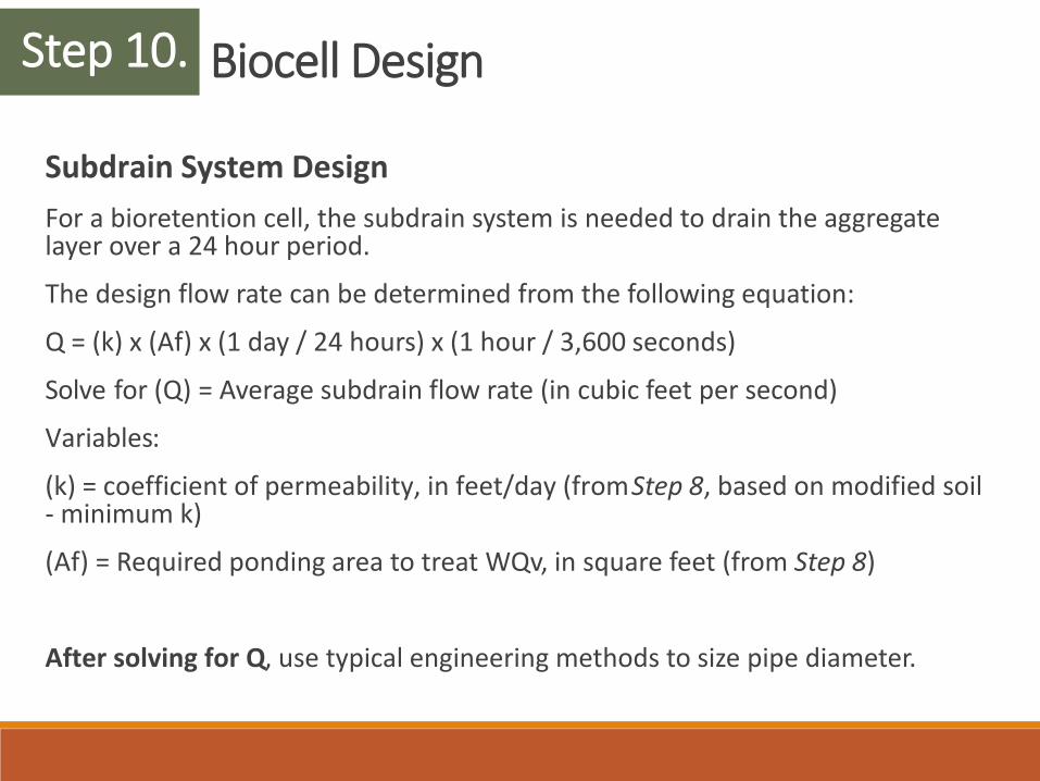
Subdrain System DesignFor a bioretention cell, the subdrain system is needed to drain the aggregate layer over a 24 hour period.
The design flow rate can be determined from the following equation:
Q = (k) x (Af) x (1 day / 24 hours) x (1 hour / 3,600 seconds)
Solve for (Q) = Average subdrain flow rate (in cubic feet per second)
Variables:
(k) = coefficient of permeability, in feet/day (from Step 8, based on modified soil - minimum k)
(Af) = Required ponding area to treat WQv, in square feet (from Step 8)
After solving for Q, use typical engineering methods to size pipe diameter.
Step 10.
Biocell Design
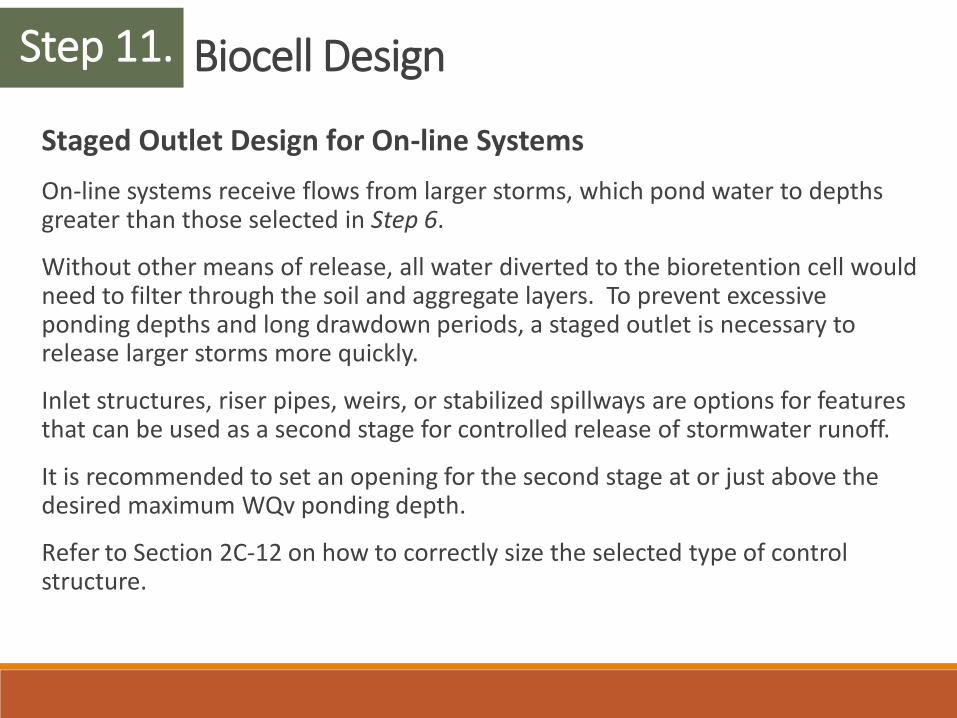
Staged Outlet Design for On-line SystemsOn-line systems receive flows from larger storms, which pond water to depths greater than those selected in Step 6.
Without other means of release, all water diverted to the bioretention cell would need to filter through the soil and aggregate layers. To prevent excessive ponding depths and long drawdown periods, a staged outlet is necessary to release larger storms more quickly.
Inlet structures, riser pipes, weirs, or stabilized spillways are options for features that can be used as a second stage for controlled release of stormwater runoff.
It is recommended to set an opening for the second stage at or just above the desired maximum WQv ponding depth.
Refer to Section 2C-12 on how to correctly size the selected type of control structure.
Step 11.
Biocell Design
Staged Outlet Design for On-line SystemsFor on-line systems, it is recommended to complete a stage-storage model of the basin created above the bioretention cell with inflow hydrographs generated in Step 2 to determine storage volumes, depths, and release rates for all relevant storm events.
To prevent compaction of the modified soil layer, excessive storage depths and drawdown times should be avoided.
For the CPv, check that ponding depths above the soil layer do not exceed 24 inches and surface drawdown does not exceed 24 hours.
For the Qp-Qf events, check that ponding depths above the soil layer do not exceed 48 inches and surface drawdown does not exceed 30 hours.
Step 11.
Biocell Design
System Outlet and Overland Spillway Design ConsiderationsCheck peak flow velocities near pipe outlets and spillways expected to be overtopped during large storms.
For all storm events reviewed, velocities at any pipe outlets should be less than 5 feet per second, and stabilization provided (refer to HEC-14).
Overflow spillways should be designed with sufficient width to keep velocities less than 5 feet per second, and be properly stabilized or reinforced to withstand such velocities.
Refer to Section 2C-12, H for additional information.
Step 12.