Embed Size (px)
Citation preview
SOIL SHEAR STRENGTH
Prepared by:
Dr. Hetty
Muhammad Azril
Fauziah Kassim
Norafida
Copyright Dr. Hetty et. al 2014
What is shear strength
Shear strength of a soil is the maximum internal
resistance to applied shearing forces
Why it is important
The safety if any geotechnical structure
dependent on the strength of the soil. If the
soil fails, a structure founded on it can
collapse, endangering lives and causing
economic damage
Copyright Dr. Hetty et. al 2014
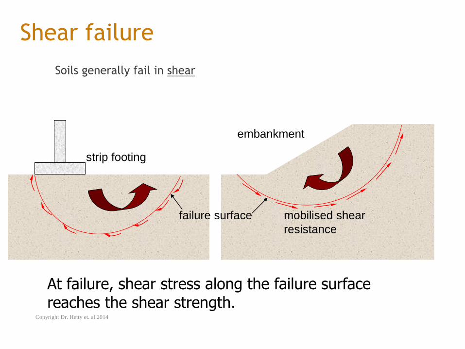
Shear failure
Soils generally fail in shear
strip footing
embankment
At failure, shear stress along the failure surface reaches the shear strength.
failure surface mobilised shear
resistance
Copyright Dr. Hetty et. al 2014
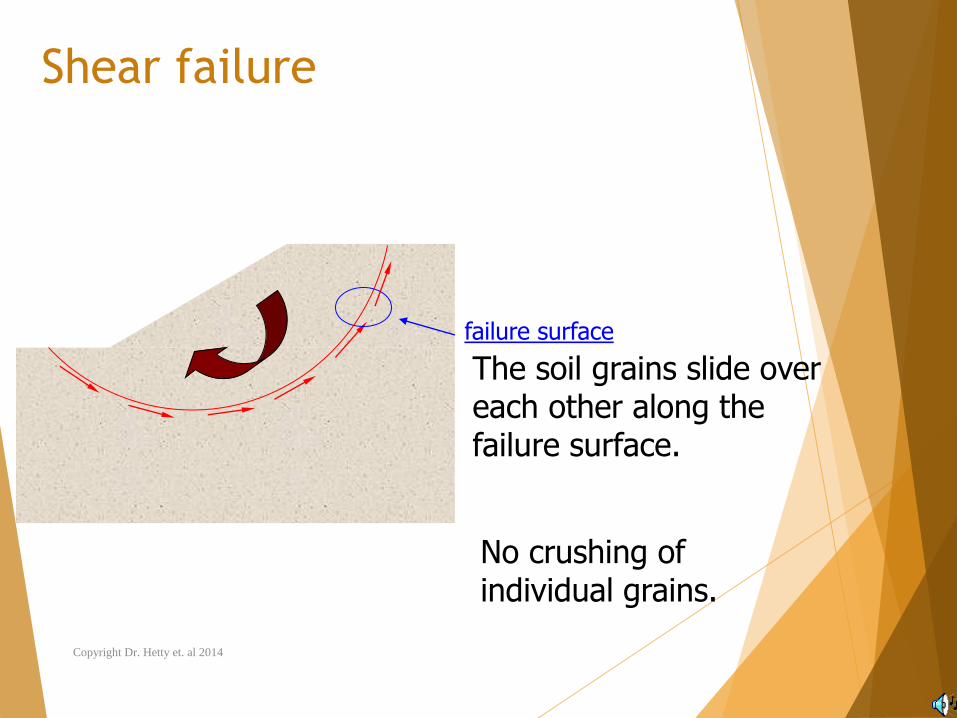
Shear failure
The soil grains slide over each other along the failure surface.
No crushing of individual grains.
failure surface
Copyright Dr. Hetty et. al 2014
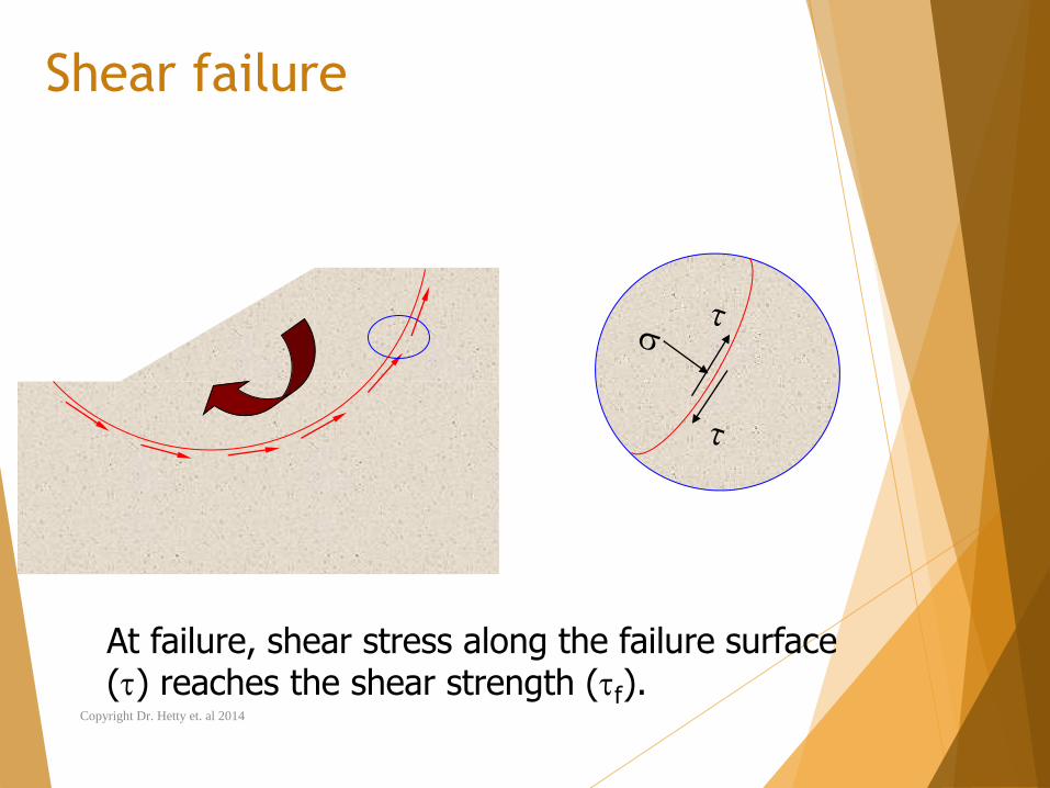
Shear failure
At failure, shear stress along the failure surface () reaches the shear strength (f).
Copyright Dr. Hetty et. al 2014
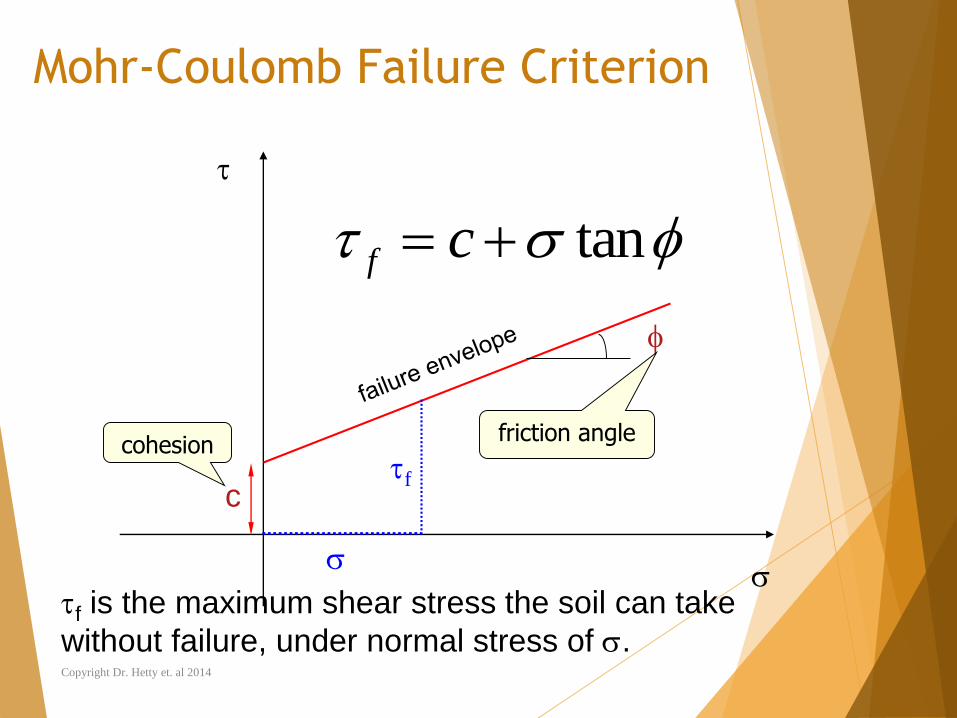
Mohr-Coulomb Failure Criterion
tan cf
c
cohesionfriction angle
f is the maximum shear stress the soil can take
without failure, under normal stress of .
f
Copyright Dr. Hetty et. al 2014
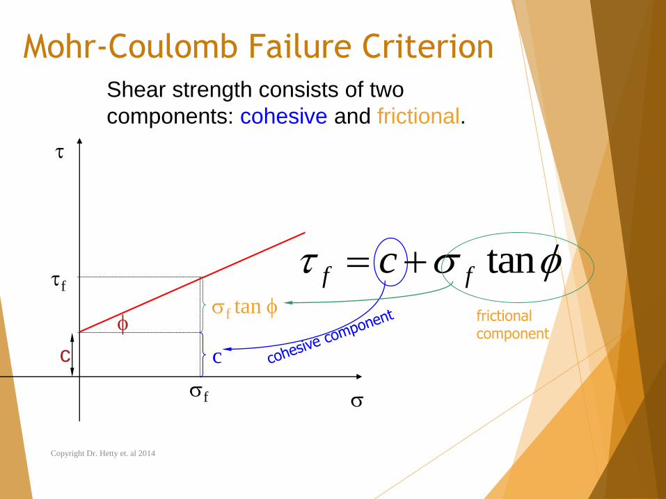
Mohr-Coulomb Failure Criterion
tanff c
Shear strength consists of two
components: cohesive and frictional.
f
f
c
f tan
c
frictional component
Copyright Dr. Hetty et. al 2014
c and are measures of shear strength.
Higher the values, higher the shear strength.
Copyright Dr. Hetty et. al 2014
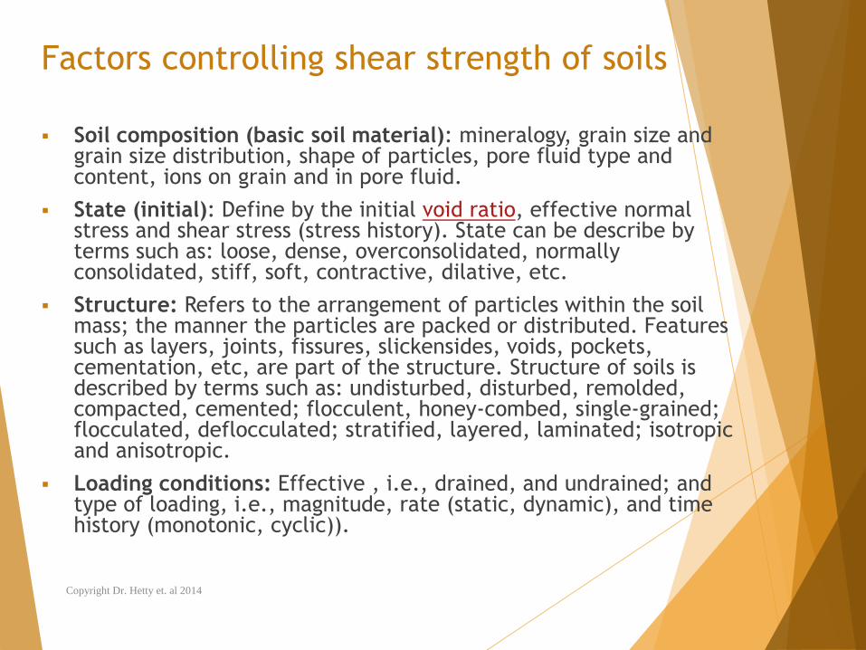
Factors controlling shear strength of soils
Soil composition (basic soil material): mineralogy, grain size and grain size distribution, shape of particles, pore fluid type and content, ions on grain and in pore fluid.
State (initial): Define by the initial void ratio, effective normal stress and shear stress (stress history). State can be describe by terms such as: loose, dense, overconsolidated, normally consolidated, stiff, soft, contractive, dilative, etc.
Structure: Refers to the arrangement of particles within the soil mass; the manner the particles are packed or distributed. Features such as layers, joints, fissures, slickensides, voids, pockets, cementation, etc, are part of the structure. Structure of soils is described by terms such as: undisturbed, disturbed, remolded, compacted, cemented; flocculent, honey-combed, single-grained; flocculated, deflocculated; stratified, layered, laminated; isotropic and anisotropic.
Loading conditions: Effective , i.e., drained, and undrained; and type of loading, i.e., magnitude, rate (static, dynamic), and time history (monotonic, cyclic)).
Copyright Dr. Hetty et. al 2014
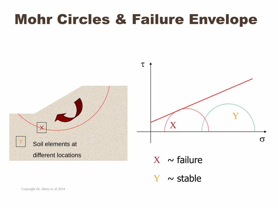
Mohr Circles & Failure Envelope
X
Y Soil elements at
different locations
XY
X
Y
~ failure
~ stable
Copyright Dr. Hetty et. al 2014
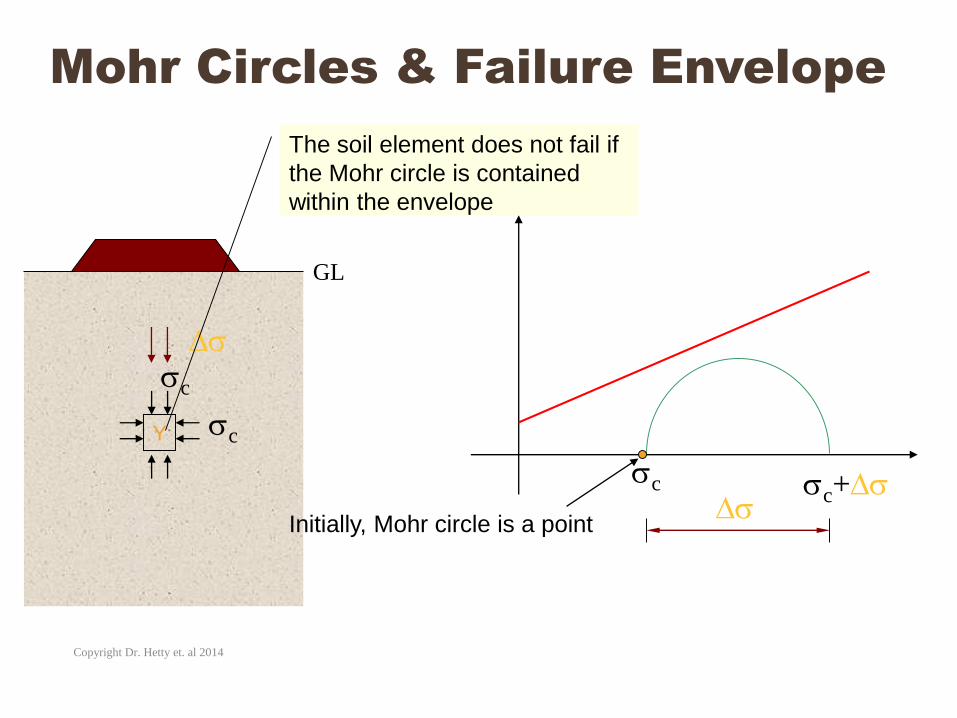
Mohr Circles & Failure Envelope
Y
Initially, Mohr circle is a point
c
c
c
c+
The soil element does not fail if
the Mohr circle is contained
within the envelope
GL
Copyright Dr. Hetty et. al 2014
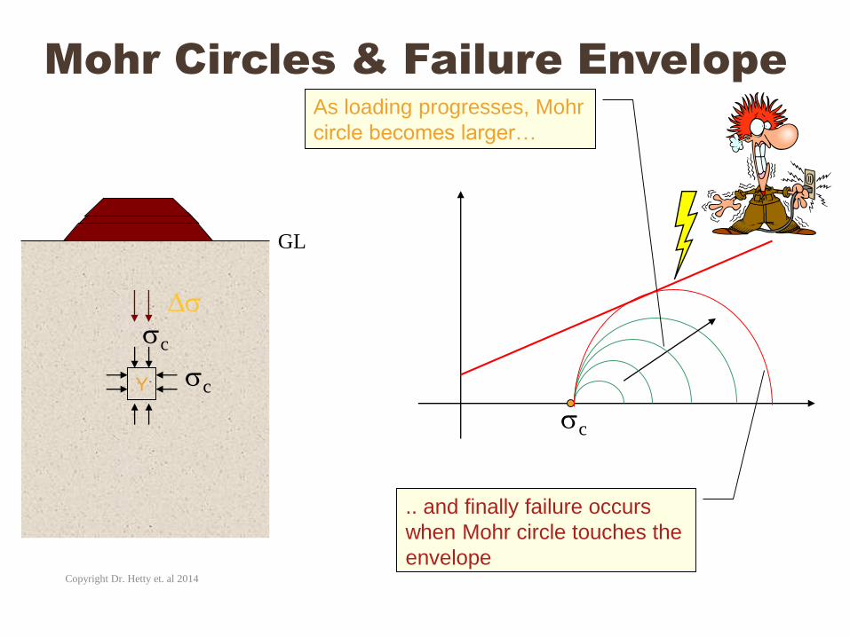
Mohr Circles & Failure Envelope
Y
c
c
c
GL
As loading progresses, Mohr
circle becomes larger…
.. and finally failure occurs
when Mohr circle touches the
envelopeCopyright Dr. Hetty et. al 2014
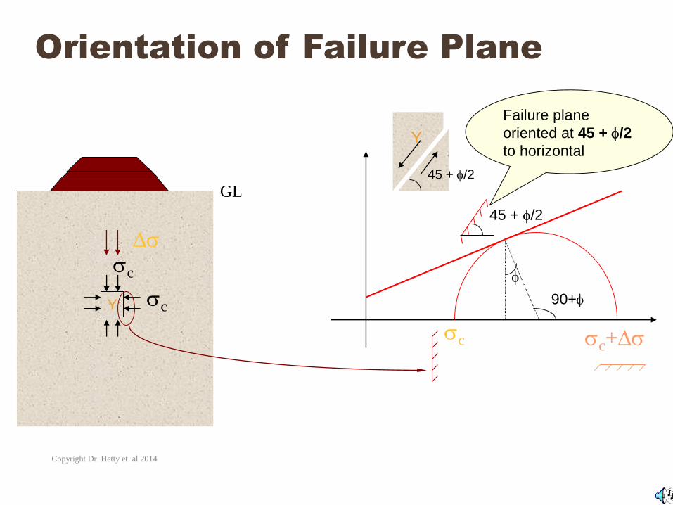
Orientation of Failure Plane
Y
c
c
c
GL
c+
90+
45 + /2
Failure plane
oriented at 45 + /2
to horizontal
45 + /2
Y
Copyright Dr. Hetty et. al 2014
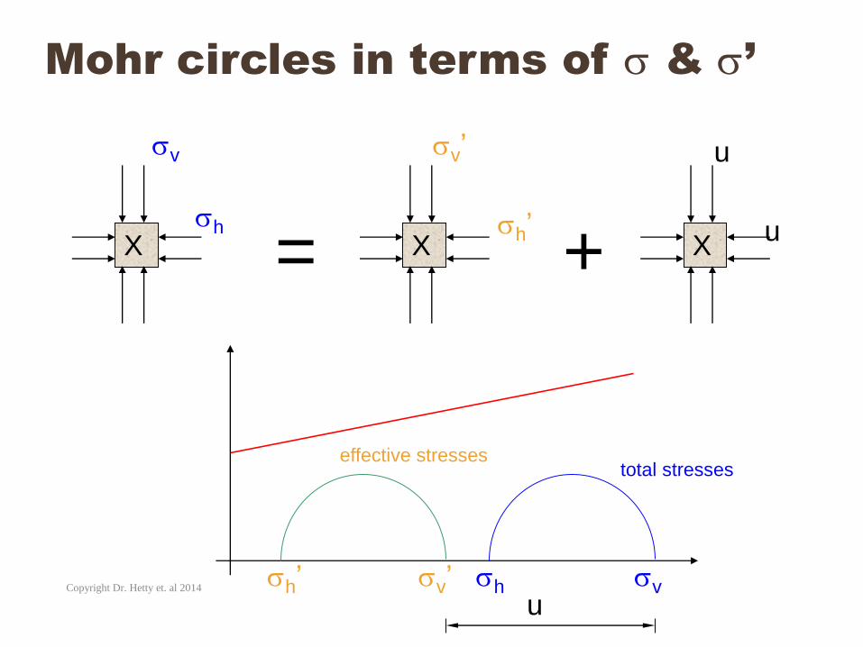
Mohr circles in terms of & ’
X X X
v
h
v’
h’
u
u
= +
total stresseseffective stresses
vhv’h’u
Copyright Dr. Hetty et. al 2014
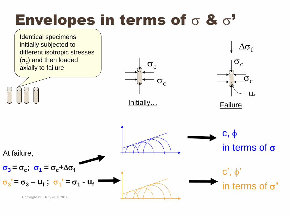
Envelopes in terms of & ’Identical specimens
initially subjected to
different isotropic stresses
(c) and then loaded
axially to failure
c
c
c
c
f
Initially… Failure
uf
At failure,
3 = c; 1 = c+f
3’= 3 – uf ; 1’ = 1 - uf
c,
c’, ’
in terms of
in terms of ’Copyright Dr. Hetty et. al 2014
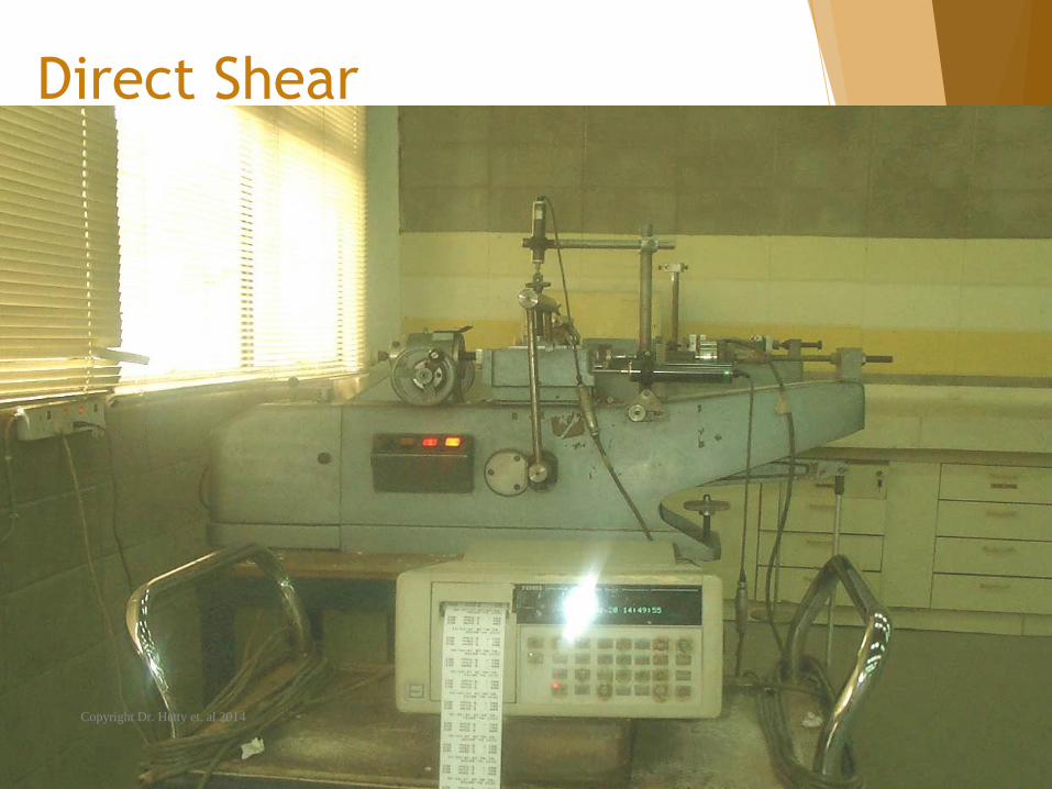
Direct Shear
Copyright Dr. Hetty et. al 2014
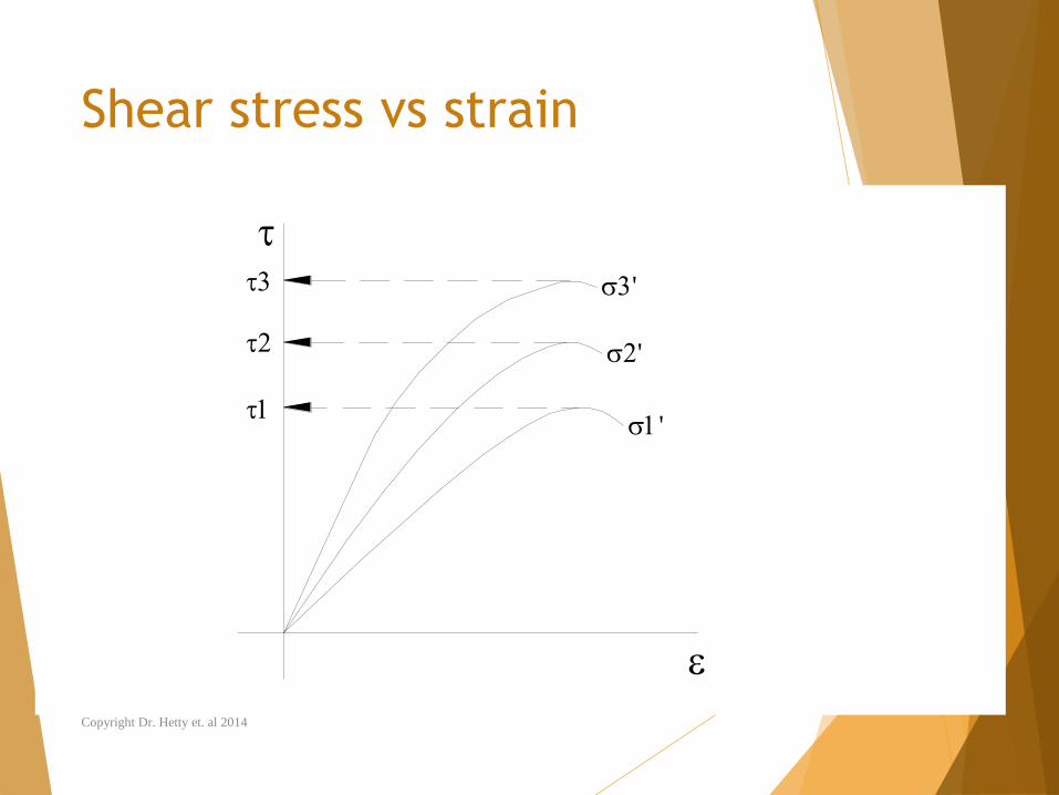
Shear stress vs strain
'
'
'
Copyright Dr. Hetty et. al 2014
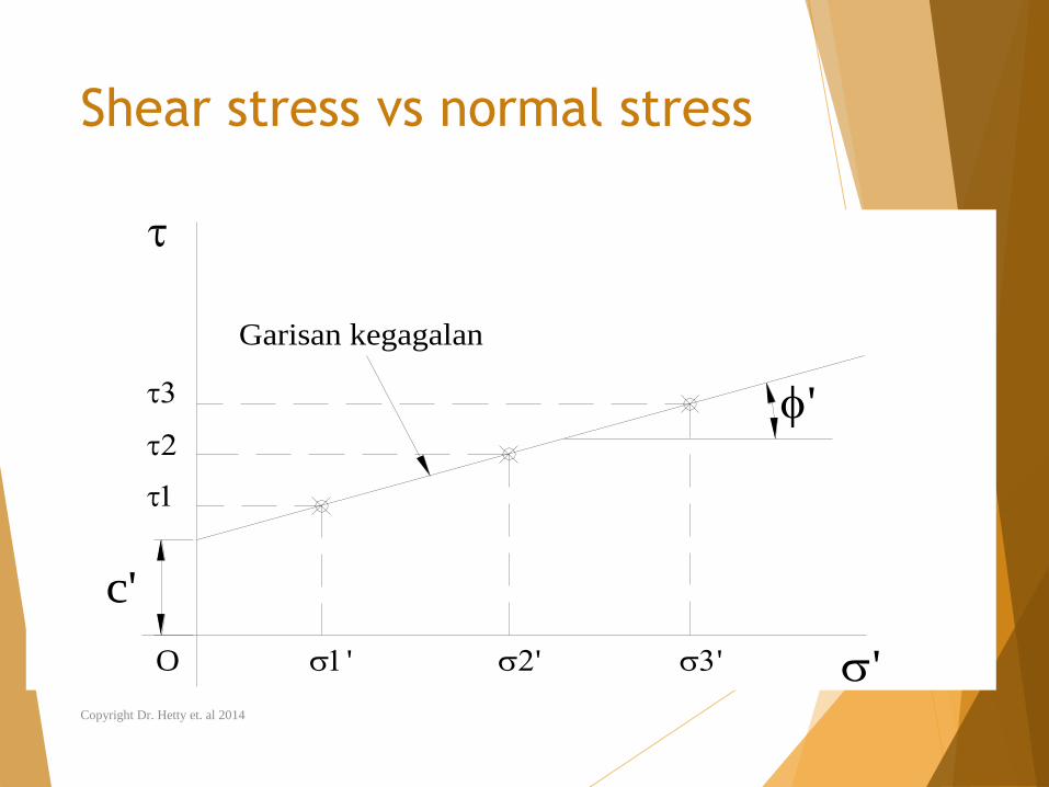
Shear stress vs normal stress
O
Garisan kegagalan
c'
'
'' ' '
Copyright Dr. Hetty et. al 2014
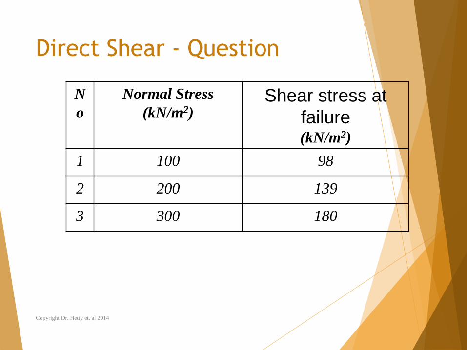
Direct Shear - Question
N
o
Normal Stress
(kN/m2) Shear stress at
failure(kN/m2)
1 100 98
2 200 139
3 300 180
Copyright Dr. Hetty et. al 2014
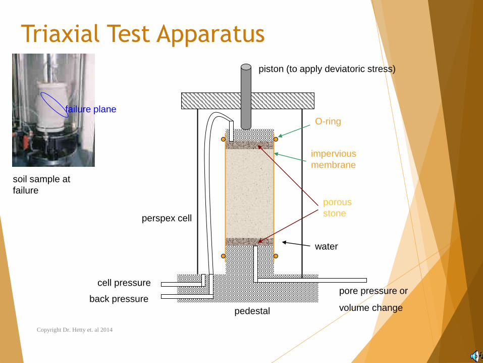
Triaxial Test Apparatus
porous
stone
impervious
membrane
piston (to apply deviatoric stress)
O-ring
pedestal
perspex cell
cell pressure
back pressurepore pressure or
volume change
water
soil sample at
failure
failure plane
Copyright Dr. Hetty et. al 2014
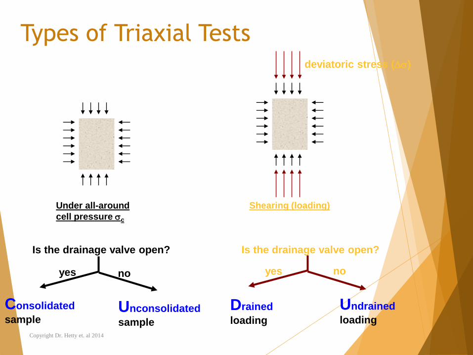
Types of Triaxial Tests
Under all-around
cell pressure c
Shearing (loading)
Is the drainage valve open? Is the drainage valve open?
deviatoric stress ()
yes no yes no
Consolidated
sampleUnconsolidated
sample
Drained
loading
Undrained
loading
Copyright Dr. Hetty et. al 2014
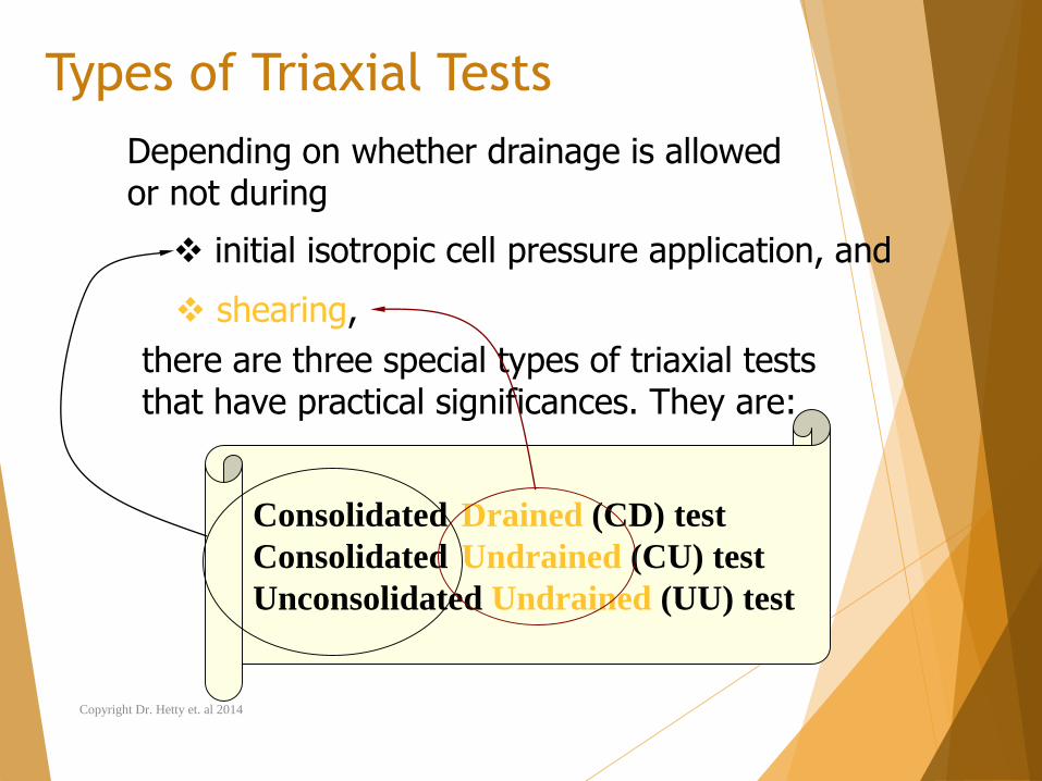
Types of Triaxial Tests
Depending on whether drainage is allowed or not during
initial isotropic cell pressure application, and
shearing,
there are three special types of triaxial tests that have practical significances. They are:
Consolidated Drained (CD) test
Consolidated Undrained (CU) test
Unconsolidated Undrained (UU) test
Copyright Dr. Hetty et. al 2014
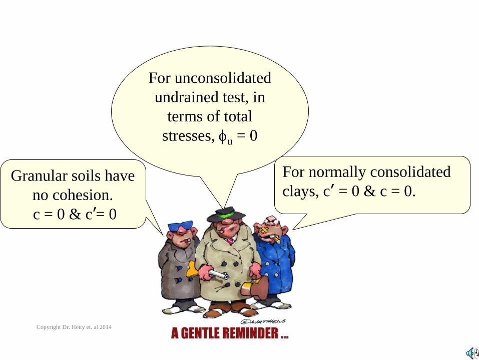
Granular soils have
no cohesion.
c = 0 & c’= 0
For normally consolidated
clays, c’ = 0 & c = 0.
For unconsolidated
undrained test, in
terms of total
stresses, u = 0
Copyright Dr. Hetty et. al 2014
CD, CU and UU Triaxial Tests
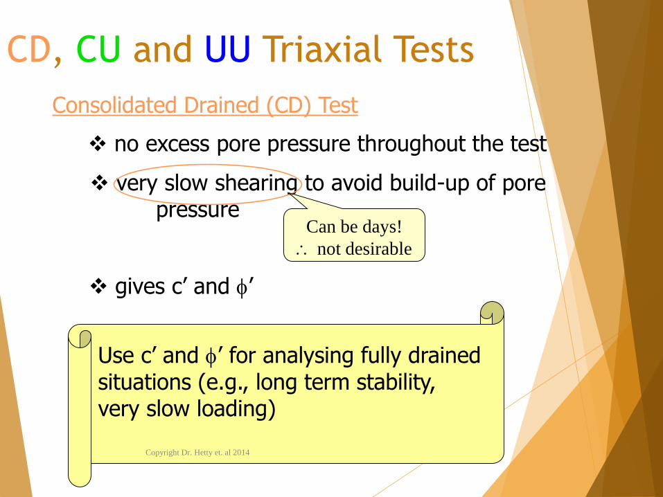
no excess pore pressure throughout the test
very slow shearing to avoid build-up of pore pressure
Consolidated Drained (CD) Test
gives c’ and ’
Can be days!
not desirable
Use c’ and ’ for analysing fully drainedsituations (e.g., long term stability, very slow loading)
Copyright Dr. Hetty et. al 2014
CD, CU and UU Triaxial Tests
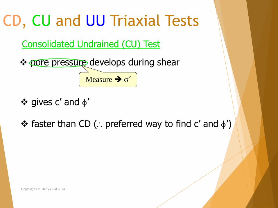
pore pressure develops during shear
faster than CD (preferred way to find c’ and ’)
Consolidated Undrained (CU) Test
gives c’ and ’
Measure ’
Copyright Dr. Hetty et. al 2014
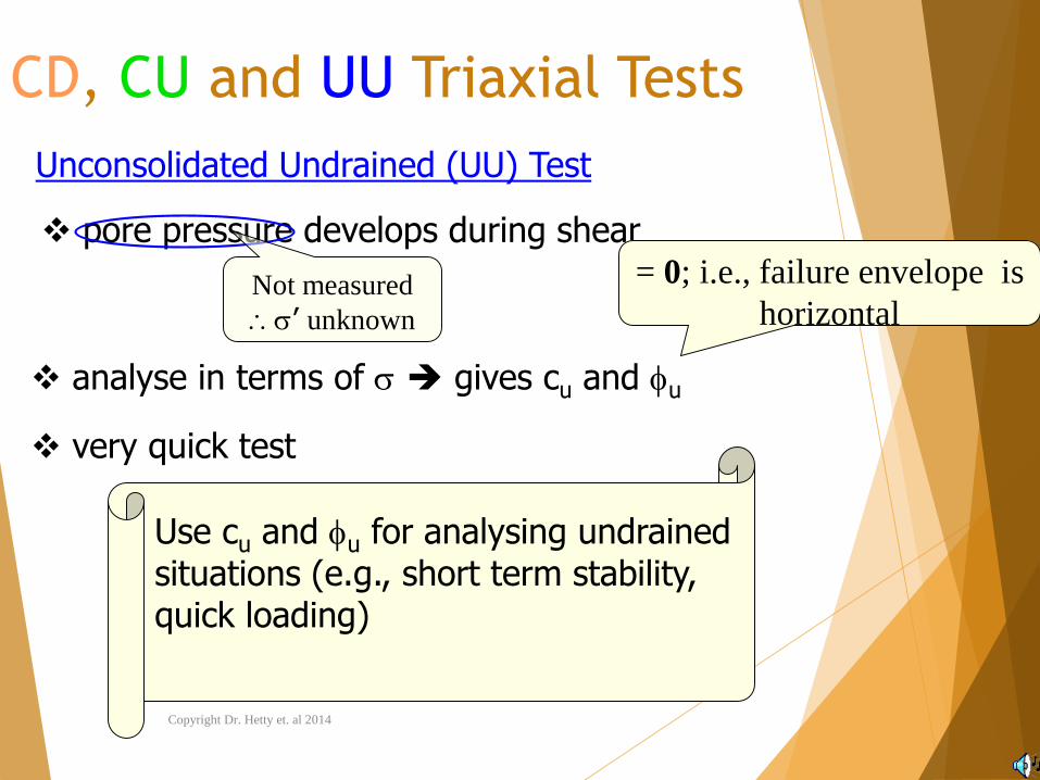
CD, CU and UU Triaxial Tests
pore pressure develops during shear
very quick test
Unconsolidated Undrained (UU) Test
analyse in terms of gives cu and u
Not measured
’ unknown
= 0; i.e., failure envelope is
horizontal
Use cu and u for analysing undrainedsituations (e.g., short term stability, quick loading)
Copyright Dr. Hetty et. al 2014
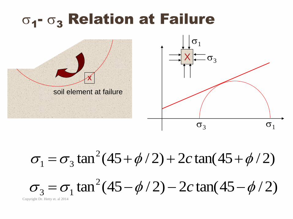
1-
3Relation at Failure
X
soil element at failure
3 1
X 3
1
)2/45tan(2)2/45(tan2
31 c
)2/45tan(2)2/45(tan2
13 cCopyright Dr. Hetty et. al 2014
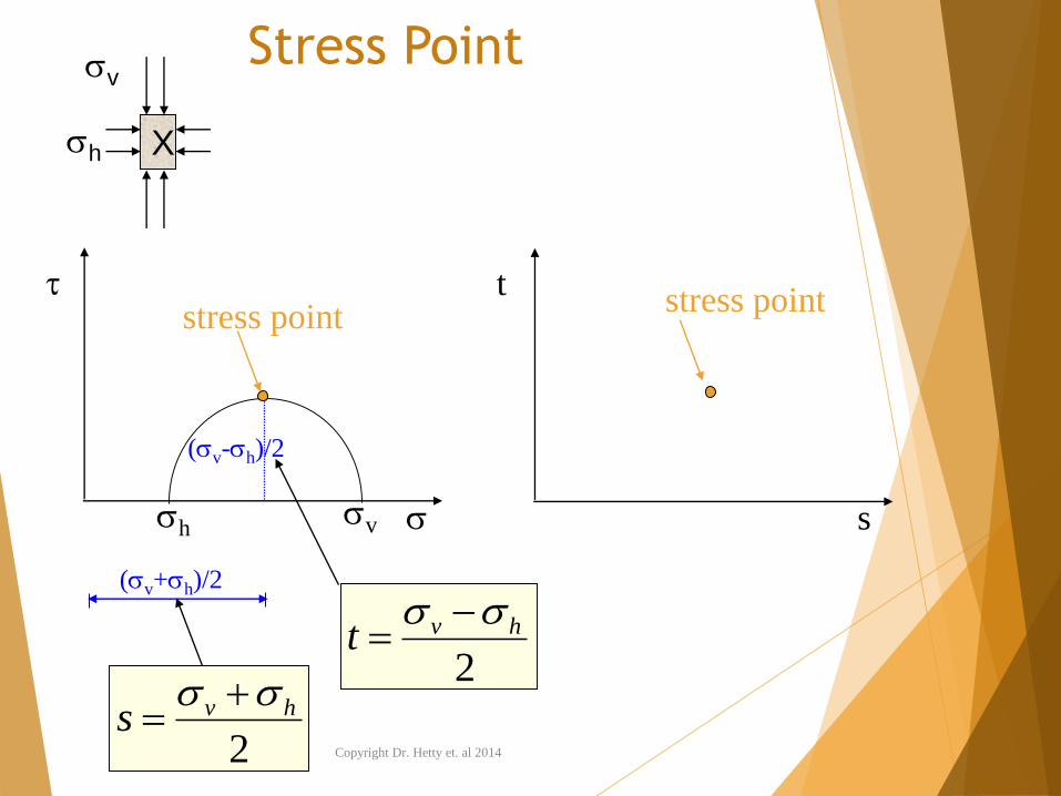
Stress Point
t
s
hv
(v-h)/2
(v+h)/2
stress pointstress point
2
hvs
2
hvt
X
v
h
Copyright Dr. Hetty et. al 2014
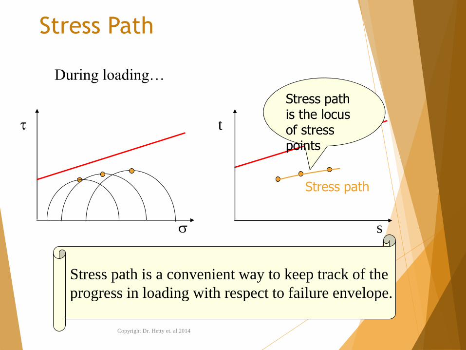
Stress Path
t
s
Stress path is the locus of stress points
Stress path
Stress path is a convenient way to keep track of the
progress in loading with respect to failure envelope.
During loading…
Copyright Dr. Hetty et. al 2014
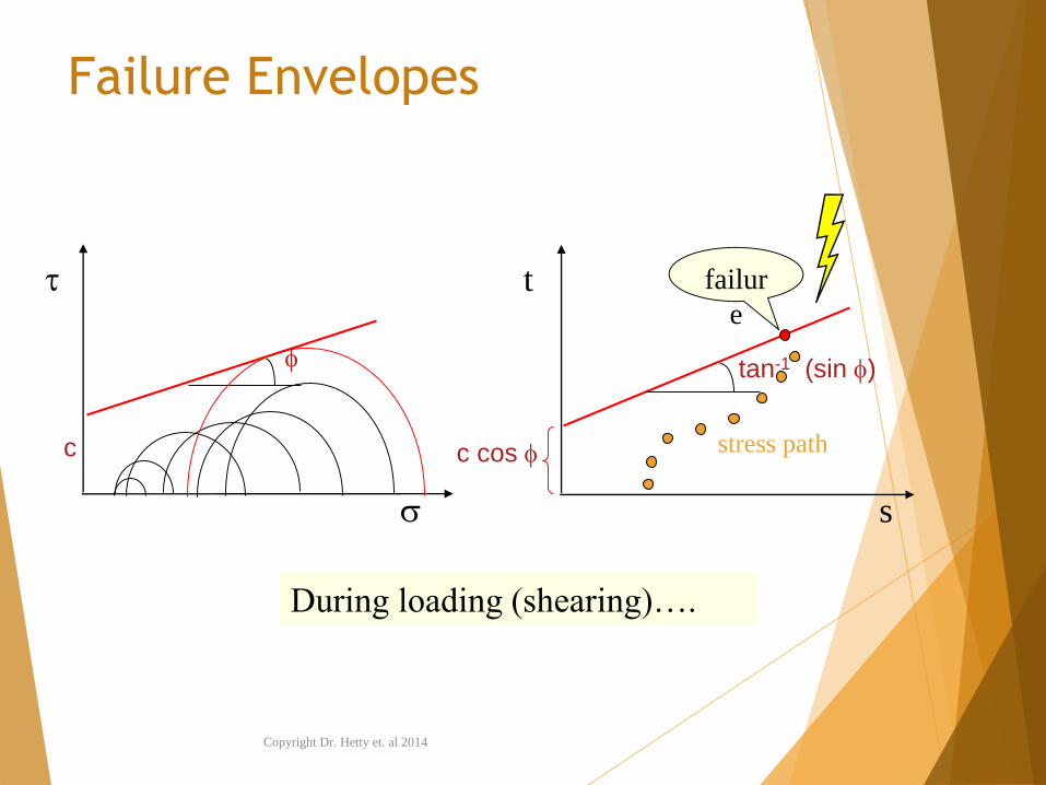
Failure Envelopes
t
s
c
c cos
tan-1 (sin )
failur
e
During loading (shearing)….
stress path
Copyright Dr. Hetty et. al 2014
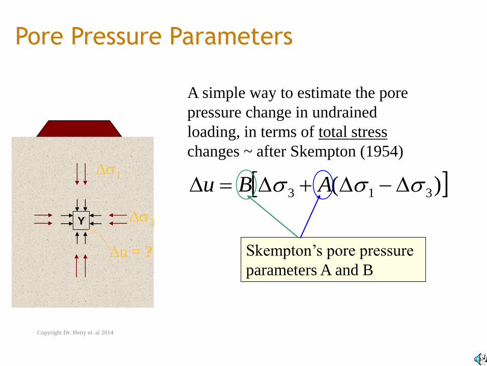
Pore Pressure Parameters
Y
1
3
u = ?
A simple way to estimate the pore
pressure change in undrained
loading, in terms of total stress
changes ~ after Skempton (1954)
)( 313 ABu
Skempton’s pore pressure
parameters A and B
Copyright Dr. Hetty et. al 2014
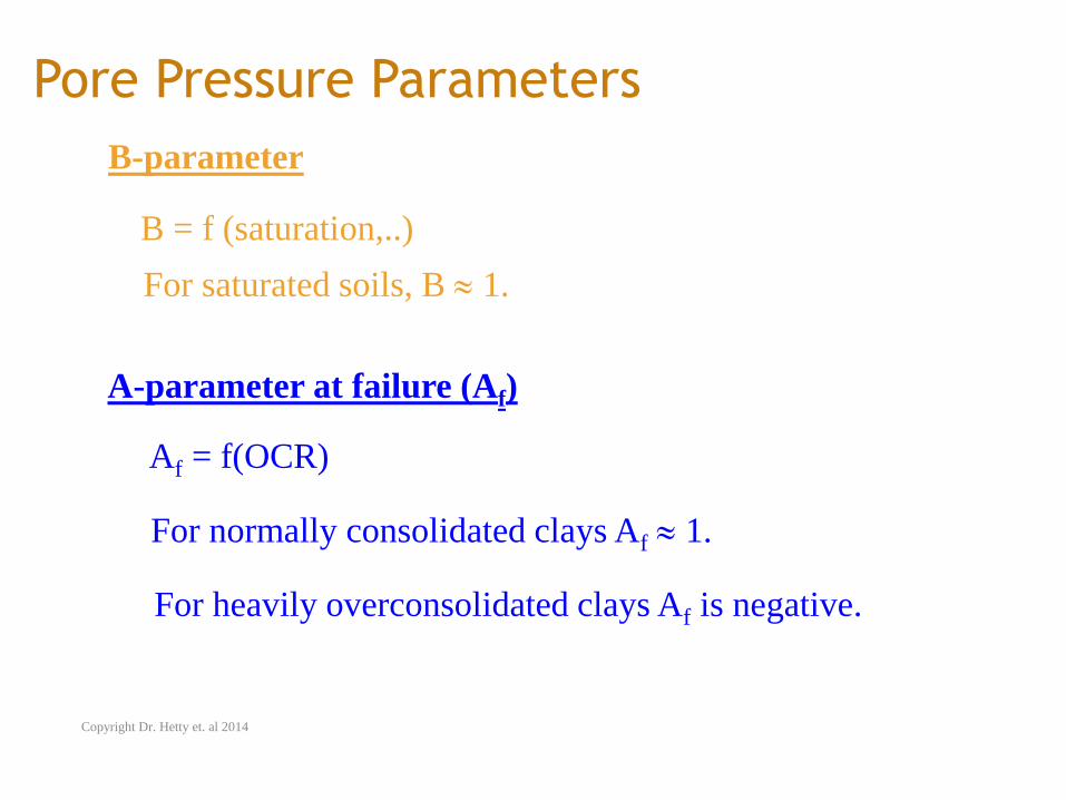
Pore Pressure Parameters
For saturated soils, B 1.
A-parameter at failure (Af)
For normally consolidated clays Af 1.
B-parameter
B = f (saturation,..)
Af = f(OCR)
For heavily overconsolidated clays Af is negative.
Copyright Dr. Hetty et. al 2014