Embed Size (px)
Citation preview

Instructions for preparing the “Streambank Soil Bioengineering Field Guide for Low Precipitation Areas” as a booklet. This version of the guide has been formatted to be printed double-sided, then folded as a booklet. If you want a copy with all the pages in order, please download the standard page format at “http://plant-materials.nrcs.usda.gov/pubs/idpmcpussbfglpa.pdf”. To make the booklet: 1. This format of the guide must be printed in duplex (double-sided) format. Either print it directly to a printer capable of duplexing,
or print it out single-sided then duplex it on a copier. Note that some resolution on the figures may be lost if copied. 2. Remove this instruction sheet from the printout. 3. Do not switch any pages. You should have a stack of 16 sheets with the turtle drawing on the left (back cover) and bird drawing
on the right (front cover). 4. Fold all the pages at the same time so the covers are correct. 5. Put 2 staples in the left binding to hold it all together. 6. As an alternative to folding, cut the entire stack of papers down the middle so you are left with 2 stacks of 5.5 x 8.5 sheets. Flip
the stack with the turtle drawing over and put it under the stack with the bird drawing. Pages should be in correct order and can be staples or bound on the left side.
Any questions about this guide should be directed to authors.

USDA- NRCS: Plant Materials Center & National Design, Construction & Soil Mechanics Center 64
USDA- NRCS: Plant Materials Center & National Design, Construction & Soil Mechanics Center 1
Streambank Soil Bioengineering Field Guide for Low Precipitation
Areas
Prepared by
Chris Hoag, Wetland Plant Ecologist, USDA-NRCS, Plant Materials Center, P.O. Box 296, Aberdeen ID 83210
And
Jon Fripp, Stream Mechanics Civil Engineer, USDA-NRCS, National Design, Construction, and Soil Mechanics Center, P.O. Box 6567, Fort Worth TX, 76115
December 2002
National Design, Construction, and Soil Mechanics Center
USDA- NRCS: Plant Materials Center & National Design, Construction & Soil Mechanics Center 2
Streambank Soil Bioengineering Field Guide for Low Precipitation Areas
Prepared by
Chris Hoag, Wetland Plant Ecologist, USDA-NRCS, Plant Materials Center, P.O. Box 296, Aberdeen ID 83210
And
Jon Fripp, Stream Mechanics Civil Engineer, USDA-NRCS, National Design, Construction, and Soil Mechanics Center, P.O. Box 6567, Fort Worth TX, 76115
December 2002 Information from this field guide may be copied and distributed with appropriate citation to the Interagency Riparian/Wetland Project and the authors. This publication is part of the technology transfer effort of the USDA-NRCS Plant Material Center, Aberdeen, ID. The United States Department of Agriculture (USDA) prohibits discrimination in all its programs and activities on the basis of race, color, national origin, gender, religion, age, disability, political beliefs, sexual orientation, and martial or familial statues. (Not all prohibited bases apply to all programs.) Persons with disabilities who require alternative means for communication of program information (Braille, large print, audiotape, etc.) should contact the USDA’s TARGET CENTER at (202) 720-2600 (voice &TDD). To file a complaint of discrimination, write USDA, Director, Office of Civil Rights, Room 326w, Whitten Building, 14th and Independence Avenue, SW, Washington, D.C. 20250-9410, or call (202) 720-5964, (voice or TDD). USDA is an equal employment opportunity provider and employer.
USDA- NRCS: Plant Materials Center & National Design, Construction & Soil Mechanics Center 63
USDA, SCS, 1947 (revised 1954) SCS Handbook of Channel Design for Soil and Water Conservation, TP-61
USDA. NRCS, 1992 Chapter 18 Soil Bioengineering for Upland Slope Protection and Erosion Control
USDA. NRCS, 1996 Chapter 16 Streambank and Shoreline Protection USDA. 1998, Stream Corridor Restoration: Principles, Processes, and
Practices. Acknowledgments
Numerous people provided expert reviews and comments. Their contributions are acknowledged and very much appreciated. The authors hope that they have listed all of the people who have contributed to this effort and trust that those who were inadvertently omitted will understand. Lee Brooks, ASTCTS, NRCS, Boise, ID Art Shoemaker, State Conservation Engineer, NRCS, Boise, ID Terril Stevenson, Geologist, NRCS, Boise, ID Tom Moody, PE, Natural Channel Designs, Flagstaff, AZ Stephanie Yard, PE, Natural Channel Design, Flagstaff, AZ Justin Krajewski, Idaho Soil Conservation Commission, Pocatello, ID Bruce Sandoval, Civil Engineer, NRCS, Pocatello, ID Hollis Allen, Ecologist, Allenvironment Consulting, Vicksburg, MS Nicholas Metes, Program and Training Specialist, AG/ENV Center for
Field Assistance and Applied Research, Peace Corps, DC Kerry Robinson, Hydraulic Engineer, NRCS, WSSI, Raleigh, NC Dave Burgdorf, Plant Materials Specialist, NRCS, East Lansing, MI Frank Cousin, Soil Bioengineer, NRCS East Lansing, MI Leland Saele, Civil Engineer, NRCS, NDSCMC, Ft. Worth, TX Danny McCook, Geotech Engineer, NRCS, NDCSMC, Ft. Worth, TX Larry Goertz, Hydraulic Engineer, NRCS, NDCSMC, Ft. Worth, TX Don Shanklin, Civil Engineer, NRCS, NDCSMC, Ft. Worth, TX Rosanna Brown, Landscape Architect, NRCS, NDCSMC, Ft. Worth, TX Wade Anderson, Civil Engineer, NRCS, NDCSMC, Ft. Worth, TX Jerry M. Bernard, National Geologist, NRCS, Washington, DC Lyle Steffen, Geologist, NRCS, National Soil Survey Center, Lincoln,NE Kevin Piper, District Manager, Dayton Valley Conservation District,
Dayton, NV Robbin Sotir, Consultant, Robbin B. Sotir & Assoc., Inc, Marietta, GA Figures have been provided by: Gary Bentrup, US Forest Service, Agroforestry Center, Lincoln NE Valeska Fripp, Earth Team Volunteer, NRCS, NDCSMC, Ft. Worth TX Juan Renteria, Civil Engineer, NRCS, NDCSMC, Ft. Worth, TX An editorial review has been provided by: Cathy Tillman, NRCS, NDCSMC, Ft. Worth, TX Funds for printing this publication were provided by USDI Bureau of Reclamation, Pacific Northwest Region

USDA- NRCS: Plant Materials Center & National Design, Construction & Soil Mechanics Center 62
cottonwoods, dogwoods, and other species. Riparian/Wetland Project Information Series No. 17. USDA-NRCS Aberdeen Plant Materials Center, Aberdeen, ID. Jan. 2001. 12 p.
Hoag, J.C., F.E. Berg, S. K. Wyman, and R.W. Sampson 2001. Riparian Planting Zones in the Intermountain West. Riparian/Wetland Project Information Series No. 16: USDA-NRCS Aberdeen Plant Materials Center, Aberdeen, ID. March 2001. 24p
Kondolf, M. 1995b. Five elements for effective evaluation of stream restoration. Restoration Ecology 3(2):133-136.
Leopold, L.B. M.G. Wolman, and J.P. Miller. 1964. Fluvial Processes in Geomorphology. Dover Publications, New York, NY.
Leopold, L.B. 1994. A View of the River. Harvard University Press, Cambridge, MD.
Lewis, L. 2000. Soil Bioengineering: An alternative for Roadside Management, A Practical Guide. USFS Technology & Development Program, 0077 1801-SDTDC, San Dimas, CA.
Minshall, G.W., S.E. Jensen, and W.S. Platts. 1989. The ecology of stream and riparian habitats of the Great Basin region: a community profile. Biol. Rep. 85(7.24). U.S. Department of Interior, Fish and Wildlife Service, National Wetlands Research Center, Slidell, LA.
Olson-Rutz, K.M. and C.B. Marlow. 1992. Analysis and interpretation of stream channel cross-sectional data. North American Journal of Fisheries Management. 12:55-61.
Piper, K.L., J.C. Hoag, H. Allen, G. Durham, and C. Fischenich. 2000. Bioengineering as a tool for restoring ecological integrity to the Carson River. ERDC TN-WRAP-01-05, Sept. 2001. USACE Waterways Experiment Station, Vicksburg, MS.
Platts, W.S. et al. 1987. Methods for Evaluating Riparian Habitats with Applications to Management. General Technical Report INT-221, USDA Forest Service, Rocky Mtn. Research Station, Ogden, UT.
Rosgen, D.L. 1996. Applied River Morphology. Wildland Hyrdrology, Pagosa Springs, CO.
Schiechtl, H.M. 1980. Bioengineering for Land Reclamation and Conservation. University of Alberta Press, Edmonton, Canada.
Schiechtl, H.M. and R. Stern. 1994. Water Bioengineering Techniques. Blackwell Science, Cambridge, MA.
Schoklitsch, A. 1937. Hydraulic Structures - A Text and Handbook, The American Society of Mechanical Engineers, New York, NY
Temple, D. 1980, Tractive Force Design of Vegetated Channels, ASCE, Transactions, A28Vol 23, No 4
USACE. 1981. Final Report to Congress: the Streambank Erosion Control Evaluation and Demonstration Act of 1974. Section 32, PL 93-251.
USACE, 1991, Hydraulic Design of Flood Control Channels, EM 1110-2-1601
USACE, 1997, WES Stream Investigation and Streambank Stabilization Handbook, D. S. Biedenharn, C.M. Elliot, and C.C Watson
USDA- NRCS: Plant Materials Center & National Design, Construction & Soil Mechanics Center 3
Streambank Soil Bioengineering Field Guide for Low Precipitation Areas
This Streambank Soil Bioengineering Field Guide is intended as a pocket field guide for many of the soil bioengineering treatments that are used to reduce streambank erosion. It has been prepared for use in the Riparian Ecology and Restoration Workshop which focuses on many of the popular streambank soil bioengineering treatments which are used in drier areas of the American West. This field guide incorporates a general discussion on riparian zones, plant materials selection criteria, and streambank soil bioengineering treatments including installation guidelines and materials requirements. This field guide also includes an appendix that provides some useful information on a variety of useful tools such as soil mechanics considerations, stream classification, rock sizing, limiting velocity and shear criterion, as well as planting tools. Datasheets describing woody plant species that are applicable to soil bioengineering treatments in the arid and semiarid Great Basin and the Intermountain West of the United States are provided. However, this field guide is neither inclusive nor exhaustive. Many publications are available which provide more detail on these as well as other treatments. The practitioner is encouraged to review these publications as well as available local knowledge of the area. Successful application of these treatments is dependent upon many site specific conditions such as stream velocity, soil conditions, soil nutrients, salinity, ice and debris load, flooding, drought, plant availability, and climate, to name a few. This Streambank Soil Bioengineering Field Guide is small enough to fit in a field pack. It is printed on water resistant paper so it can be used in most any weather. The user is encouraged to take notes on the pages. The information in the field book is meant to provide a quick reference while in the field working on a project. This guide is not intended to be an exhaustive design tool. While the appendix contains overview information, this field guide is not intended for the final design of rock structures such as deflectors, weirs, or riprap revetments nor is it intended to provide sufficient information for a geotechnical slope stability analysis. Rather this field guide should be viewed as a general field reference and review document.
Table of Contents
INTRODUCTION.................................................................................. 5
RIPARIAN PLANTING ZONES ......................................................... 5
CHOICE OF PLANT MATERIAL...................................................... 7
STREAMBANK SOIL BIOENGINEERING TREATMENTS......... 9

USDA- NRCS: Plant Materials Center & National Design, Construction & Soil Mechanics Center 4
POLE PLANTINGS............................................................................... 10 BRUSH OR TREE REVETMENT........................................................... 11 BRUSH MATTRESS ............................................................................. 14 FASCINES ........................................................................................... 15 VERTICAL BUNDLES .......................................................................... 16 BRUSH LAYERING.............................................................................. 17 BRUSH PACKING ................................................................................ 18 LOG CRIBWALLS ............................................................................... 19 CRIMPING AND SEEDING ................................................................... 21 WATTLE SILTATION FENCE .............................................................. 22 WATTLE SILTATION FENCE AS AN EROSION STOP .......................... 23 STONE SILL WITH LIVE JOINT PLANTINGS ...................................... 24 LIVE BRUSH SILLS............................................................................. 25 BRUSH TRENCH ................................................................................. 26 BRUSH SPURS..................................................................................... 27 STONE IN BIOENGINEERING .............................................................. 29
APPENDIX OF USEFUL INFORMATION ..................................... 31
PRE FIELD WORK.............................................................................. 32 STREAM ASSESSMENT PROCEDURE.................................................. 33 LIMITING VELOCITY AND SHEAR CRITERION ................................. 34 FLUVIAL GEOMORPHOLOGY AND CLASSIFICATION ........................ 37 TREATMENT STRATEGIES BASED ON CLASSIFICATION ................... 40 STONE SIZING .................................................................................... 43 LOW HEAD STONE GRADE CONTROL WEIRS .................................. 46 SOIL MECHANICS CONSIDERATIONS ................................................ 48 UNIFIED SOIL CLASSIFICATION ........................................................ 49 SEDIMENT GRADE SCALE ................................................................. 51 BASIC SURVEYING ............................................................................. 51 WATERJET STINGER ......................................................................... 53
PLANT DATASHEETS ...................................................................... 54
YELLOW WILLOW - SALIX LUTEA .................................................... 55 PACIFIC WILLOW - SALIX LUCIDA SSP. LASIANDRA ........................ 55 GEYER WILLOW - SALIX GEYERIANA............................................... 56 COYOTE WILLOW - SALIX EXIGUA ................................................... 56 DRUMMOND WILLOW - SALIX DRUMMONDIANA ............................. 57 BOOTH WILLOW - SALIX BOOTHII.................................................... 57 PEACHLEAF WILLOW - SALIX AMYGDALOIDES ............................... 58 BLACK COTTONWOOD - POPULUS TRICHOCARPA ........................... 58 NARROWLEAF COTTONWOOD - POPULUS ANGUSTIFOLIA............... 59 WATER (BLACK) BIRCH - BETULA OCCIDENTALIS .......................... 59 THINLEAF ALDER - ALNUS INCANA SPP. TENUIFOLIA ...................... 60 REDOSIER DOGWOOD - CORNUS SERICEA........................................ 60
RIPARIAN REFERENCES................................................................ 61
ACKNOWLEDGMENTS ................................................................... 63
USDA- NRCS: Plant Materials Center & National Design, Construction & Soil Mechanics Center 61
Riparian References There are many publications that are available, which provide more detail on issues related to stream bank soil bioengineering. A partial list is provided below, however, this list is neither inclusive nor exhaustive. Allen, H.H. and J.R. Leech. 1997. Bioengineering Guidelines for
Streambank Erosion Control. Environmental Impact Research Program Technical Report. U.S. Army Corps of Engineers Waterways Experiment Station. Technical Report EL-97-8
ASCE. 1975, Sedimentation Engineering, Engineering Practice No. 54 Bentrup, G and J.C. Hoag 1998. The Practical Streambank
Bioengineering Guide: a User’s Guide for Natural Streambank Stabilization Techniques in the Arid and Semi-arid Great Basin and Intermountain West. Interagency Riparian/Wetland Project, Plant Materials Center, USDA-NRCS, Aberdeen, ID.
Beschta, R.L. and W.S. Platts. 1986. Morphological features of small streams: significance and function. Water Resources Bulletin 22(3):369-379.
Carlson, J.R., G.L. Conaway, J.L. Gibbs, and J.C. Hoag. 1995. Design Criteria for Revegetation in Riparian Zones of the Intermountain Area. USDA NRCS Riparian/Wetland Project Information Series #9, Plant Materials Center, Aberdeen, ID.
Chang, H.H. 1992. Fluvial Processes in River Engineering. Krieger Publishing Co, Malabar, FL.
Copeland, R.R., D.N. McComas, C.R. Thorne, P.J. Soar, M.M. Jonas, and J.B. Fripp, 2001, Hydraulic Design of Stream Restoration Projects, U.S. Army Corps of Engineers. ERDC/CHL TR-01-28
Firehock, K. and J. Doherty, 1995. A Citizen's Streambank Restoration Handbook. Save our Streams, Izaak Walton League of America, Inc., Gaithersburg, MD.
Fischenich, J.C. and H.H. Allen 1999. Stream Management. US Army Corp of Engineers, Ft. Worth District, Ft. Worth, TX.
Gerstgraser, 1999, The effect and resistance of soil bioengineering methods for streambank protection, Proceedings of Conf 30, IECA, Nashville TN
Gordon, N.D., T.A. McMahon, and B.L. Finlayson. 1992. Stream hydrology: an introduction for ecologists. John Wiley and Sons, New York, NY.
Gray, D.H. and R.B. Sotir. 1996. Biotechnical and Soil Bioengineering Slope Stabilization. John Wiley and Sons, Inc. New York, NY.
Gray, D.H. and A.T. Leiser. 1982. Biotechnical Slope Protection and Erosion Control. Van Nostrand Reinhold, New York, NY.
Hoag, J.C. 1993a. Selection and acquisition of woody plant species and materials for riparian corridors and shorelines. USDA NRCS Riparian/Wetland Project Information Series #2, Plant Materials Center, Aberdeen, ID.
Hoag, J.C, B. Simonson, B. Cornforth, and L. St. John 2001. Waterjet Stinger: A tool to plant dormant unrooted cuttings of willows,
USDA- NRCS: Plant Materials Center & National Design, Construction & Soil Mechanics Center 60
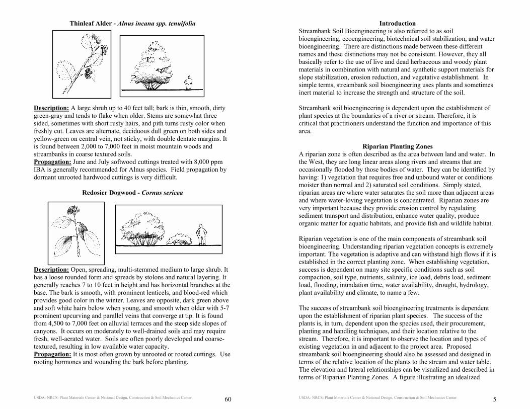
Thinleaf Alder - Alnus incana spp. tenuifolia Description: A large shrub up to 40 feet tall; bark is thin, smooth, dirty green-gray and tends to flake when older. Stems are somewhat three sided, sometimes with short rusty hairs, and pith turns rusty color when freshly cut. Leaves are alternate, deciduous dull green on both sides and yellow-green on central vein, not sticky, with double dentate margins. It is found between 2,000 to 7,000 feet in moist mountain woods and streambanks in coarse textured soils. Propagation: June and July softwood cuttings treated with 8,000 ppm IBA is generally recommended for Alnus species. Field propagation by dormant unrooted hardwood cuttings is very difficult.
Redosier Dogwood - Cornus sericea
Description: Open, spreading, multi-stemmed medium to large shrub. It has a loose rounded form and spreads by stolons and natural layering. It generally reaches 7 to 10 feet in height and has horizontal branches at the base. The bark is smooth, with prominent lenticels, and blood-red which provides good color in the winter. Leaves are opposite, dark green above and soft white hairs below when young, and smooth when older with 5-7 prominent upcurving and parallel veins that converge at tip. It is found from 4,500 to 7,000 feet on alluvial terraces and the steep side slopes of canyons. It occurs on moderately to well-drained soils and may require fresh, well-aerated water. Soils are often poorly developed and coarse-textured, resulting in low available water capacity. Propagation: It is most often grown by unrooted or rooted cuttings. Use rooting hormones and wounding the bark before planting.
USDA- NRCS: Plant Materials Center & National Design, Construction & Soil Mechanics Center 5
Introduction Streambank Soil Bioengineering is also referred to as soil bioengineering, ecoengineering, biotechnical soil stabilization, and water bioengineering. There are distinctions made between these different names and these distinctions may not be consistent. However, they all basically refer to the use of live and dead herbaceous and woody plant materials in combination with natural and synthetic support materials for slope stabilization, erosion reduction, and vegetative establishment. In simple terms, streambank soil bioengineering uses plants and sometimes inert material to increase the strength and structure of the soil. Streambank soil bioengineering is dependent upon the establishment of plant species at the boundaries of a river or stream. Therefore, it is critical that practitioners understand the function and importance of this area.
Riparian Planting Zones A riparian zone is often described as the area between land and water. In the West, they are long linear areas along rivers and streams that are occasionally flooded by those bodies of water. They can be identified by having: 1) vegetation that requires free and unbound water or conditions moister than normal and 2) saturated soil conditions. Simply stated, riparian areas are where water saturates the soil more than adjacent areas and where water-loving vegetation is concentrated. Riparian zones are very important because they provide erosion control by regulating sediment transport and distribution, enhance water quality, produce organic matter for aquatic habitats, and provide fish and wildlife habitat. Riparian vegetation is one of the main components of streambank soil bioengineering. Understanding riparian vegetation concepts is extremely important. The vegetation is adaptive and can withstand high flows if it is established in the correct planting zone. When establishing vegetation, success is dependent on many site specific conditions such as soil compaction, soil type, nutrients, salinity, ice load, debris load, sediment load, flooding, inundation time, water availability, drought, hydrology, plant availability and climate, to name a few. The success of streambank soil bioengineering treatments is dependent upon the establishment of riparian plant species. The success of the plants is, in turn, dependent upon the species used, their procurement, planting and handling techniques, and their location relative to the stream. Therefore, it is important to observe the location and types of existing vegetation in and adjacent to the project area. Proposed streambank soil bioengineering should also be assessed and designed in terms of the relative location of the plants to the stream and water table. The elevation and lateral relationships can be visualized and described in terms of Riparian Planting Zones. A figure illustrating an idealized
USDA- NRCS: Plant Materials Center & National Design, Construction & Soil Mechanics Center 6
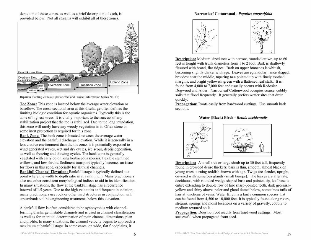
depiction of these zones, as well as a brief description of each, is provided below. Not all streams will exhibit all of these zones. Toe Zone: This zone is located below the average water elevation or baseflow. The cross-sectional area at this discharge often defines the limiting biologic condition for aquatic organisms. Typically this is the zone of highest stress. It is vitally important to the success of any stabilization project that the toe is stabilized. Due to the long inundation, this zone will rarely have any woody vegetation in it. Often stone or some inert protection is required for this zone. Bank Zone: The bank zone is located between the average water elevation and the bankfull discharge elevation. While it is generally in a less erosive environment than the toe zone, it is potentially exposed to wind generated waves, wet and dry cycles, ice scour, debris deposition, as well as freezing and thawing cycles. The bank zone is generally vegetated with early colonizing herbaceous species, flexible stemmed willows, and low shrubs. Sediment transport typically becomes an issue for flows in this zone, especially for alluvial channels. Bankfull Channel Elevation: Bankfull stage is typically defined at a point where the width to depth ratio is at a minimum. Many practitioners also use other consistent morphological indices to aid in its identification. In many situations, the flow at the bankfull stage has a recurrence interval of 1.5-years. Due to the high velocities and frequent inundation, many practitioners use rock or other hard structures in conjunction with streambank soil bioengineering treatments below this elevation. A bankfull flow is often considered to be synonymous with channel-forming discharge in stable channels and is used in channel classification as well as for an initial determination of main channel dimensions, plan and profile. In many situations, the channel velocity begins to approach a maximum at bankfull stage. In some cases, on wide, flat floodplains, it
Flood Prone Elev.
Riparian Planting Zones (Riparian/Wetland Project Information Series No. 16)
Avg. WE Bankfull Elev Overbank Elev.
Toe Zone
Bank Zone
Overbank Zone Transition ZoneUpland Zone
Flood Prone Elev.
USDA- NRCS: Plant Materials Center & National Design, Construction & Soil Mechanics Center 59
Narrowleaf Cottonwood - Populus angustifolia Description: Medium-sized tree with narrow, rounded crown, up to 60 feet in height with trunk diameters from 1 to 2 foot. Bark is shallowly fissured with broad, flat ridges. Bark on upper branches is whitish, becoming slightly darker with age. Leaves are eglandular, lance shaped, broadest near the middle, tapering to a pointed tip with finely toothed margins, and bright yellowish green with a flattened leaf stalk. It is found from 4,000 to 7,000 feet and usually occurs with Redosier Dogwood and Alder. Narrowleaf Cottonwood occupies coarse, cobbly soils that flood frequently. It generally prefers wetter sites that drain quickly. Propagation: Roots easily from hardwood cuttings. Use smooth bark sections.
Water (Black) Birch - Betula occidentalis
Description: A small tree or large shrub up to 30 feet tall, frequently found in crowded dense thickets; bark is thin, smooth, almost black on young trees, turning reddish-brown with age. Twigs are slender, upright, covered with numerous glands (small bumps). The leaves are alternate, deciduous, with rounded wedge shaped base and pointed tip, leaf base is entire extending to double row of fine sharp-pointed teeth, dark greenish-yellow and shiny above, paler and gland dotted below, sometimes tufts of hair at junctions of veins. Water Birch is a fairly common species that can be found from 4,500 to 10,000 feet. It is typically found along rivers, streams, springs and moist locations on a variety of gravelly, cobbly to medium textured soils. Propagation: Does not root readily from hardwood cuttings. Most successful when propagated from seed.
USDA- NRCS: Plant Materials Center & National Design, Construction & Soil Mechanics Center 58
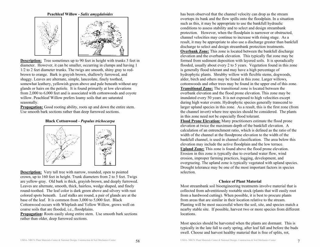
Peachleaf Willow - Salix amygdaloides
Description: Tree sometimes up to 90 feet in height with trunks 3 feet in diameter. However, it can be smaller, occurring in clumps and having 1 1/2 to 2 feet diameter trunks. The twigs are smooth, shiny gray to red-brown to orange. Bark is grayish brown, shallowly furrowed, and shaggy. Leaves are alternate, simple, lanceolate, finely toothed, somewhat leathery, yellowish green above and pale beneath without any glands or hairs on the petiole. It is found primarily at low elevations from 2,000 to 6,000 feet and is associated with cottonwoods and coyote willow. Peachleaf Willow prefers loamy soils that are saturated seasonally. Propagation: Good rooting ability, roots up and down the entire stem. Use smooth bark sections rather than deep furrowed sections.
Black Cottonwood - Populus trichocarpa
Description: Very tall tree with narrow, rounded, open to pointed crown, up to 160 feet in height. Trunk diameters from 2 to 5 feet. Twigs are yellow-gray. Old bark is thick, grayish-brown, and deeply furrowed. Leaves are alternate, smooth, thick, hairless, wedge shaped, and finely round-toothed. The leaf color is dark green above and silvery with rust colored spots beneath. Leaf stalks are round, a pair of glands are at the base of the leaf. It is common from 3,000 to 5,000 feet. Black Cottonwood occurs with Whiplash and Yellow Willow, grows well on coarse soils that are flooded, i.e., floodplains. Propagation: Roots easily along entire stem. Use smooth bark sections rather than older, deep furrowed sections.
USDA- NRCS: Plant Materials Center & National Design, Construction & Soil Mechanics Center 7
has been observed that the channel velocity can drop as the stream overtops its bank and the flow spills onto the floodplain. In a situation such as this, it may be appropriate to use the bankfull hydraulic conditions to assess stability and to select and design streambank protection. However, when the floodplain is narrower or obstructed, channel velocities may continue to increase with rising stage. As a result, it may be appropriate to also use a discharge greater than bankfull discharge to select and design streambank protection treatments. Overbank Zone: This zone is located between the bankfull discharge elevation and the overbank elevation. This typically flat zone may be formed from sediment deposition with layered soils. It is sporadically flooded, usually about every 2 to 5 years. Vegetation found in this zone is generally flood tolerant and may have a high percentage of hydrophytic plants. Shrubby willow with flexible stems, dogwoods, alder, birch and others may be found in this zone. Larger willows, cottonwoods and other trees may be found in the upper end of this zone. Transitional Zone: The transitional zone is located between the overbank elevation and the flood prone elevation. This zone may be inundated every 50 years. It is not exposed to high velocities except during high water events. Hydrophytic species generally transcend to larger upland species in this zone. As a result, this is the first zone (from the channel invert) where tree species should be considered. The plants in this zone need not be especially flood tolerant. Flood Prone Elevation: Many practitioners estimate the flood prone elevation at twice the maximum depth of the bankfull elevation. A calculation of an entrenchment ratio, which is defined as the ratio of the width of the channel at the floodprone elevation to the width of the bankfull channel, is used in channel classification. The area below this elevation may include the active floodplain and the low terrace. Upland Zone: This zone is found above the flood prone elevation. Erosion in this zone is typically due to overland water flow, wind erosion, improper farming practices, logging, development, and overgrazing. The upland zone is typically vegetated with upland species. Drought tolerance may be one of the most important factors in species selection.
Choice of Plant Material Most streambank soil bioengineering treatments involve material that is collected from adventitiously rootable stock (plants that will easily root from a hardwood cutting). When possible, it is best to procure plants from areas that are similar in their location relative to the stream. Planting will be most successful where the soil, site, and species match a nearby stable site. If possible, harvest two or more species from different locations. Most species should be harvested when the plants are dormant. This is typically in the late fall to early spring, after leaf fall and before the buds swell. Choose and harvest healthy material that is free of splits, rot,
USDA- NRCS: Plant Materials Center & National Design, Construction & Soil Mechanics Center 8
disease, and insect infestation. While it is often appropriate to include material that ranges in age up to 4 years, material should be harvested from plants that are at least 2 years old. In drier areas, one year old stock should not be used. This younger material is often too small and does not have enough stored energy for good root establishment. Harvesting of live material should leave at least one third of the parent plant intact. The equipment should be sharp enough to make clean cuts. Soak material before planting for a minimum of 24 hours in cool, aerated water. Optimum time for soaking is 5 to 7 days but they can also be planted the same day as harvested if they are watered. If it is necessary to harvest material significantly before installation, the cuttings should be stored dry at approximately 33 to 40 degrees F. Live hardwood cuttings can last up to four months if refrigerated. Stored material should be soaked before planting. If the harvested material is stored under wet conditions for longer than 10 days, the root process may start. These initial roots are typically very tender making it difficult to use the material in many of the treatments without damaging them. Hardwood cuttings can be divided into four general categories: whips, poles (sometimes referred to as stakes), posts, and bundles. Whips are typically one year old material. Because of their small size, they should not be used in drier areas or areas without consistent water. Pole cuttings can made be from shrub and tree species and usually ranges in diameter from ¾ to 3 inches. Post plantings are from tree species and range in diameter from 3 to 6 inches. Bundles are packages of smaller diameter cuttings from various species with the branches left intact. Local expertise and guidelines should be consulted when selecting the appropriate plant material. A partial list of some woody species available in the arid and semiarid Great Basin and the Intermountain West of the United States is provided in Appendix of Useful Information.
Live pole collection
Soaking
USDA- NRCS: Plant Materials Center & National Design, Construction & Soil Mechanics Center 57
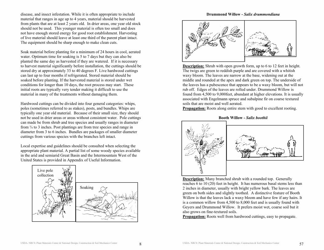
Drummond Willow - Salix drummondiana
Description: Shrub with open growth form, up to 6 to 12 feet in height. The twigs are green to reddish purple and are covered with a whitish waxy bloom. The leaves are narrow at the base, widening out at the middle and rounded at the apex and dark green on top. The underside of the leaves has a pubescence that appears to be a waxy bloom, but will not rub off. Edges of the leaves are rolled under. Drummond Willow is found from 4,500 to 9,000feet, abundant at higher elevations. It is usually associated with Engelmann spruce and subalpine fir on coarse textured soils that are moist and well aerated. Propagation: Roots along entire stem with good to excellent rooting.
Booth Willow - Salix boothii
Description: Many branched shrub with a rounded top. Generally reaches 6 to 10 (20) feet in height. It has numerous basal stems less than 2 inches in diameter, usually with bright yellow bark. The leaves are green on both sides and slightly toothed. A distinctive feature of Booth Willow is that the leaves lack a waxy bloom and have few if any hairs. It is a common willow from 4,500 to 8,000 feet and is usually found with Geyers and Drummond Willow. It prefers moist wet, coarse soil but it also grows on fine-textured soils. Propagation: Roots well from hardwood cuttings, easy to propagate.
USDA- NRCS: Plant Materials Center & National Design, Construction & Soil Mechanics Center 56
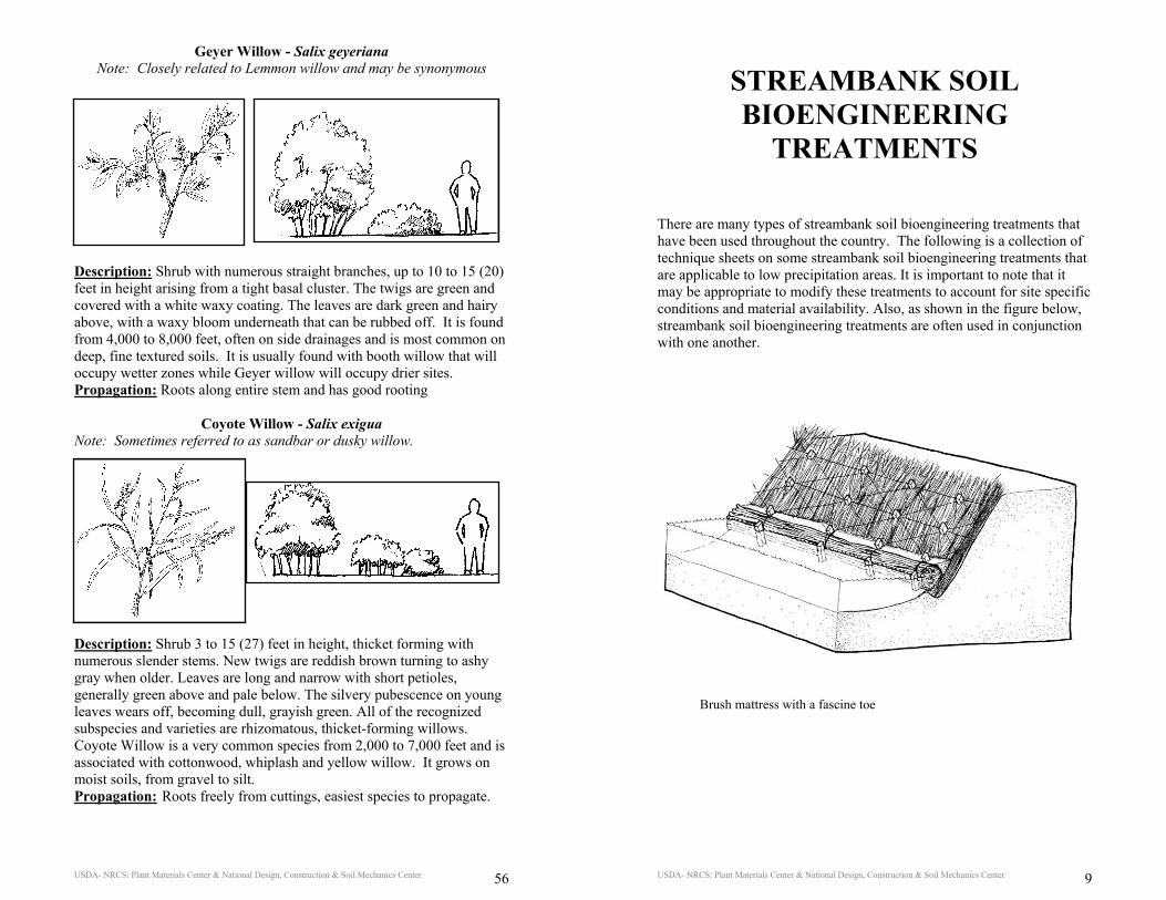
Geyer Willow - Salix geyeriana Note: Closely related to Lemmon willow and may be synonymous
Description: Shrub with numerous straight branches, up to 10 to 15 (20) feet in height arising from a tight basal cluster. The twigs are green and covered with a white waxy coating. The leaves are dark green and hairy above, with a waxy bloom underneath that can be rubbed off. It is found from 4,000 to 8,000 feet, often on side drainages and is most common on deep, fine textured soils. It is usually found with booth willow that will occupy wetter zones while Geyer willow will occupy drier sites. Propagation: Roots along entire stem and has good rooting
Coyote Willow - Salix exigua
Note: Sometimes referred to as sandbar or dusky willow.
Description: Shrub 3 to 15 (27) feet in height, thicket forming with numerous slender stems. New twigs are reddish brown turning to ashy gray when older. Leaves are long and narrow with short petioles, generally green above and pale below. The silvery pubescence on young leaves wears off, becoming dull, grayish green. All of the recognized subspecies and varieties are rhizomatous, thicket-forming willows. Coyote Willow is a very common species from 2,000 to 7,000 feet and is associated with cottonwood, whiplash and yellow willow. It grows on moist soils, from gravel to silt. Propagation: Roots freely from cuttings, easiest species to propagate.
USDA- NRCS: Plant Materials Center & National Design, Construction & Soil Mechanics Center 9
STREAMBANK SOIL BIOENGINEERING
TREATMENTS There are many types of streambank soil bioengineering treatments that have been used throughout the country. The following is a collection of technique sheets on some streambank soil bioengineering treatments that are applicable to low precipitation areas. It is important to note that it may be appropriate to modify these treatments to account for site specific conditions and material availability. Also, as shown in the figure below, streambank soil bioengineering treatments are often used in conjunction with one another.
Brush mattress with a fascine toe
USDA- NRCS: Plant Materials Center & National Design, Construction & Soil Mechanics Center 10
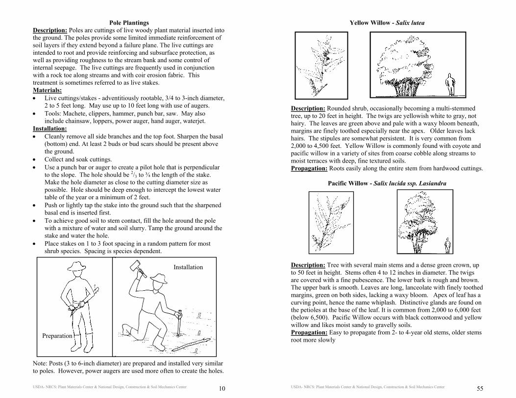
Pole Plantings Description: Poles are cuttings of live woody plant material inserted into the ground. The poles provide some limited immediate reinforcement of soil layers if they extend beyond a failure plane. The live cuttings are intended to root and provide reinforcing and subsurface protection, as well as providing roughness to the stream bank and some control of internal seepage. The live cuttings are frequently used in conjunction with a rock toe along streams and with coir erosion fabric. This treatment is sometimes referred to as live stakes. Materials: • Live cuttings/stakes - adventitiously rootable, 3/4 to 3-inch diameter,
2 to 5 feet long. May use up to 10 feet long with use of augers. • Tools: Machete, clippers, hammer, punch bar, saw. May also
include chainsaw, loppers, power auger, hand auger, waterjet. Installation: • Cleanly remove all side branches and the top foot. Sharpen the basal
(bottom) end. At least 2 buds or bud scars should be present above the ground.
• Collect and soak cuttings. • Use a punch bar or auger to create a pilot hole that is perpendicular
to the slope. The hole should be 2/3 to ¾ the length of the stake. Make the hole diameter as close to the cutting diameter size as possible. Hole should be deep enough to intercept the lowest water table of the year or a minimum of 2 feet.
• Push or lightly tap the stake into the ground such that the sharpened basal end is inserted first.
• To achieve good soil to stem contact, fill the hole around the pole with a mixture of water and soil slurry. Tamp the ground around the stake and water the hole.
• Place stakes on 1 to 3 foot spacing in a random pattern for most shrub species. Spacing is species dependent.
Note: Posts (3 to 6-inch diameter) are prepared and installed very similar to poles. However, power augers are used more often to create the holes.
Preparation
Installation
USDA- NRCS: Plant Materials Center & National Design, Construction & Soil Mechanics Center 55
Yellow Willow - Salix lutea
Description: Rounded shrub, occasionally becoming a multi-stemmed tree, up to 20 feet in height. The twigs are yellowish white to gray, not hairy. The leaves are green above and pale with a waxy bloom beneath, margins are finely toothed especially near the apex. Older leaves lack hairs. The stipules are somewhat persistent. It is very common from 2,000 to 4,500 feet. Yellow Willow is commonly found with coyote and pacific willow in a variety of sites from coarse cobble along streams to moist terraces with deep, fine textured soils. Propagation: Roots easily along the entire stem from hardwood cuttings.
Pacific Willow - Salix lucida ssp. Lasiandra
Description: Tree with several main stems and a dense green crown, up to 50 feet in height. Stems often 4 to 12 inches in diameter. The twigs are covered with a fine pubescence. The lower bark is rough and brown. The upper bark is smooth. Leaves are long, lanceolate with finely toothed margins, green on both sides, lacking a waxy bloom. Apex of leaf has a curving point, hence the name whiplash. Distinctive glands are found on the petioles at the base of the leaf. It is common from 2,000 to 6,000 feet (below 6,500). Pacific Willow occurs with black cottonwood and yellow willow and likes moist sandy to gravelly soils. Propagation: Easy to propagate from 2- to 4-year old stems, older stems root more slowly
USDA- NRCS: Plant Materials Center & National Design, Construction & Soil Mechanics Center 54
PLANT DATASHEETS
FOR COMMON RIPARIAN WOODY PLANTS OF THE WESTERN UNITED STATES*
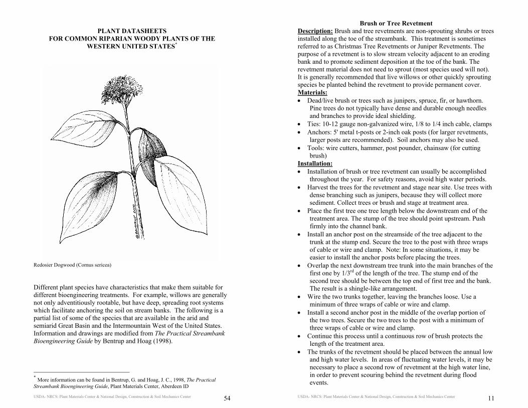
Redosier Dogwood (Cornus sericea) Different plant species have characteristics that make them suitable for different bioengineering treatments. For example, willows are generally not only adventitiously rootable, but have deep, spreading root systems which facilitate anchoring the soil on stream banks. The following is a partial list of some of the species that are available in the arid and semiarid Great Basin and the Intermountain West of the United States. Information and drawings are modified from The Practical Streambank Bioengineering Guide by Bentrup and Hoag (1998).
* More information can be found in Bentrup, G. and Hoag, J. C., 1998, The Practical Streambank Bioengineering Guide, Plant Materials Center, Aberdeen ID
USDA- NRCS: Plant Materials Center & National Design, Construction & Soil Mechanics Center 11
Brush or Tree Revetment Description: Brush and tree revetments are non-sprouting shrubs or trees installed along the toe of the streambank. This treatment is sometimes referred to as Christmas Tree Revetments or Juniper Revetments. The purpose of a revetment is to slow stream velocity adjacent to an eroding bank and to promote sediment deposition at the toe of the bank. The revetment material does not need to sprout (most species used will not). It is generally recommended that live willows or other quickly sprouting species be planted behind the revetment to provide permanent cover. Materials: • Dead/live brush or trees such as junipers, spruce, fir, or hawthorn.
Pine trees do not typically have dense and durable enough needles and branches to provide ideal shielding.
• Ties: 10-12 gauge non-galvanized wire, 1/8 to 1/4 inch cable, clamps • Anchors: 5' metal t-posts or 2-inch oak posts (for larger revetments,
larger posts are recommended). Soil anchors may also be used. • Tools: wire cutters, hammer, post pounder, chainsaw (for cutting
brush) Installation: • Installation of brush or tree revetment can usually be accomplished
throughout the year. For safety reasons, avoid high water periods. • Harvest the trees for the revetment and stage near site. Use trees with
dense branching such as junipers, because they will collect more sediment. Collect trees or brush and stage at treatment area.
• Place the first tree one tree length below the downstream end of the treatment area. The stump of the tree should point upstream. Push firmly into the channel bank.
• Install an anchor post on the streamside of the tree adjacent to the trunk at the stump end. Secure the tree to the post with three wraps of cable or wire and clamp. Note: In some situations, it may be easier to install the anchor posts before placing the trees.
• Overlap the next downstream tree trunk into the main branches of the first one by 1/3rd of the length of the tree. The stump end of the second tree should be between the top end of first tree and the bank. The result is a shingle-like arrangement.
• Wire the two trunks together, leaving the branches loose. Use a minimum of three wraps of cable or wire and clamp.
• Install a second anchor post in the middle of the overlap portion of the two trees. Secure the two trees to the post with a minimum of three wraps of cable or wire and clamp.
• Continue this process until a continuous row of brush protects the length of the treatment area.
• The trunks of the revetment should be placed between the annual low and high water levels. In areas of fluctuating water levels, it may be necessary to place a second row of revetment at the high water line, in order to prevent scouring behind the revetment during flood events.
USDA- NRCS: Plant Materials Center & National Design, Construction & Soil Mechanics Center 12
• Fill in the space between the bank and the revetment with branches or fascines to create a dense matrix.
• It is critical that the revetment extends upstream and downstream for a minimum of one tree length past the eroded area being treated to prevent flows from getting behind the revetment. It is advisable to key the upstream and downstream ends of the revetment into the bank and reinforce the key with additional brush or rock. These endpoints are the areas that are most likely to fail and require substantial protection.
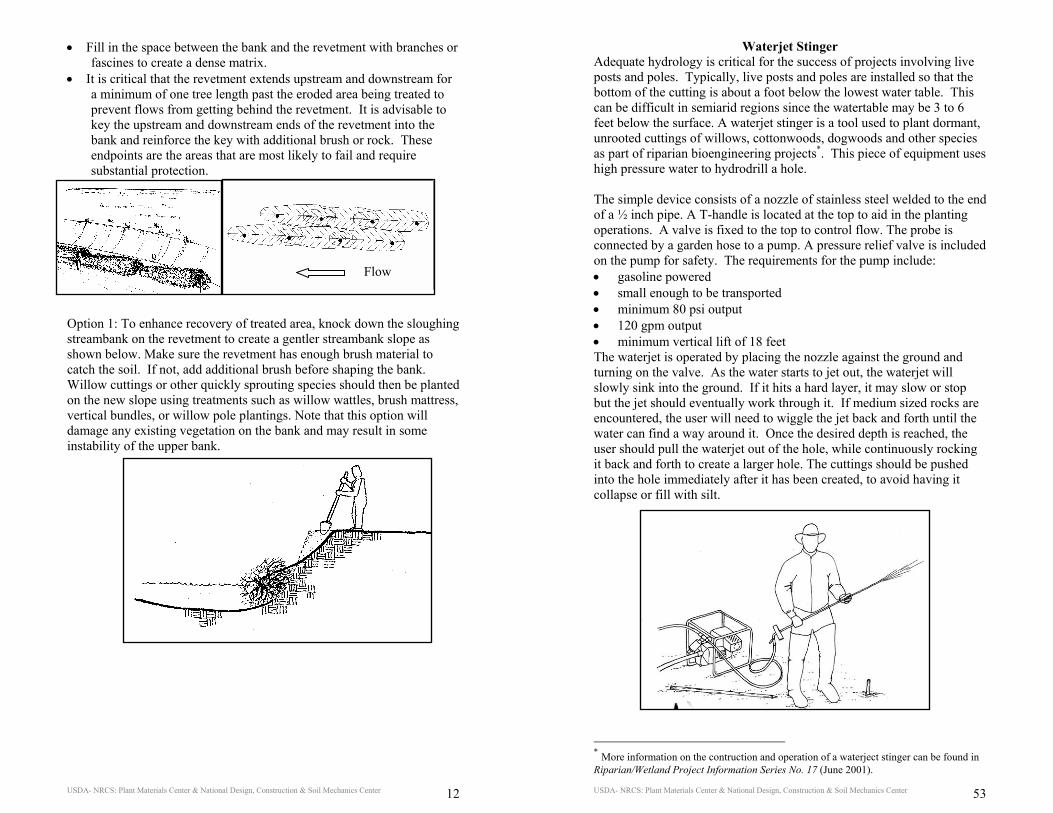
Option 1: To enhance recovery of treated area, knock down the sloughing streambank on the revetment to create a gentler streambank slope as shown below. Make sure the revetment has enough brush material to catch the soil. If not, add additional brush before shaping the bank. Willow cuttings or other quickly sprouting species should then be planted on the new slope using treatments such as willow wattles, brush mattress, vertical bundles, or willow pole plantings. Note that this option will damage any existing vegetation on the bank and may result in some instability of the upper bank.
Flow
USDA- NRCS: Plant Materials Center & National Design, Construction & Soil Mechanics Center 53
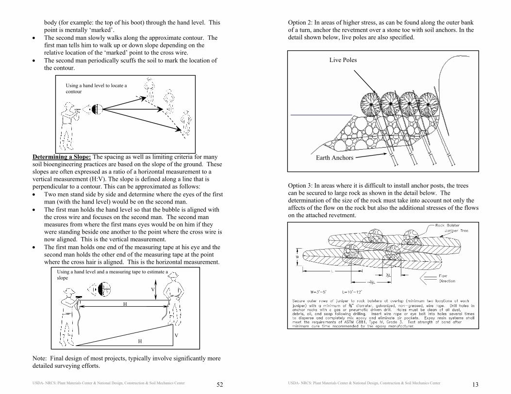
Waterjet Stinger Adequate hydrology is critical for the success of projects involving live posts and poles. Typically, live posts and poles are installed so that the bottom of the cutting is about a foot below the lowest water table. This can be difficult in semiarid regions since the watertable may be 3 to 6 feet below the surface. A waterjet stinger is a tool used to plant dormant, unrooted cuttings of willows, cottonwoods, dogwoods and other species as part of riparian bioengineering projects*. This piece of equipment uses high pressure water to hydrodrill a hole. The simple device consists of a nozzle of stainless steel welded to the end of a ½ inch pipe. A T-handle is located at the top to aid in the planting operations. A valve is fixed to the top to control flow. The probe is connected by a garden hose to a pump. A pressure relief valve is included on the pump for safety. The requirements for the pump include: • gasoline powered • small enough to be transported • minimum 80 psi output • 120 gpm output • minimum vertical lift of 18 feet The waterjet is operated by placing the nozzle against the ground and turning on the valve. As the water starts to jet out, the waterjet will slowly sink into the ground. If it hits a hard layer, it may slow or stop but the jet should eventually work through it. If medium sized rocks are encountered, the user will need to wiggle the jet back and forth until the water can find a way around it. Once the desired depth is reached, the user should pull the waterjet out of the hole, while continuously rocking it back and forth to create a larger hole. The cuttings should be pushed into the hole immediately after it has been created, to avoid having it collapse or fill with silt.
* More information on the contruction and operation of a waterject stinger can be found in Riparian/Wetland Project Information Series No. 17 (June 2001).
USDA- NRCS: Plant Materials Center & National Design, Construction & Soil Mechanics Center 52
body (for example: the top of his boot) through the hand level. This point is mentally ‘marked’.
• The second man slowly walks along the approximate contour. The first man tells him to walk up or down slope depending on the relative location of the ‘marked’ point to the cross wire.
• The second man periodically scuffs the soil to mark the location of the contour.
Determining a Slope: The spacing as well as limiting criteria for many soil bioengineering practices are based on the slope of the ground. These slopes are often expressed as a ratio of a horizontal measurement to a vertical measurement (H:V). The slope is defined along a line that is perpendicular to a contour. This can be approximated as follows: • Two men stand side by side and determine where the eyes of the first
man (with the hand level) would be on the second man. • The first man holds the hand level so that the bubble is aligned with
the cross wire and focuses on the second man. The second man measures from where the first mans eyes would be on him if they were standing beside one another to the point where the cross wire is now aligned. This is the vertical measurement.
• The first man holds one end of the measuring tape at his eye and the second man holds the other end of the measuring tape at the point where the cross hair is aligned. This is the horizontal measurement.
Note: Final design of most projects, typically involve significantly more detailed surveying efforts.
Using a hand level to locate a contour
V
H
V H
Using a hand level and a measuring tape to estimate a slope
USDA- NRCS: Plant Materials Center & National Design, Construction & Soil Mechanics Center 13
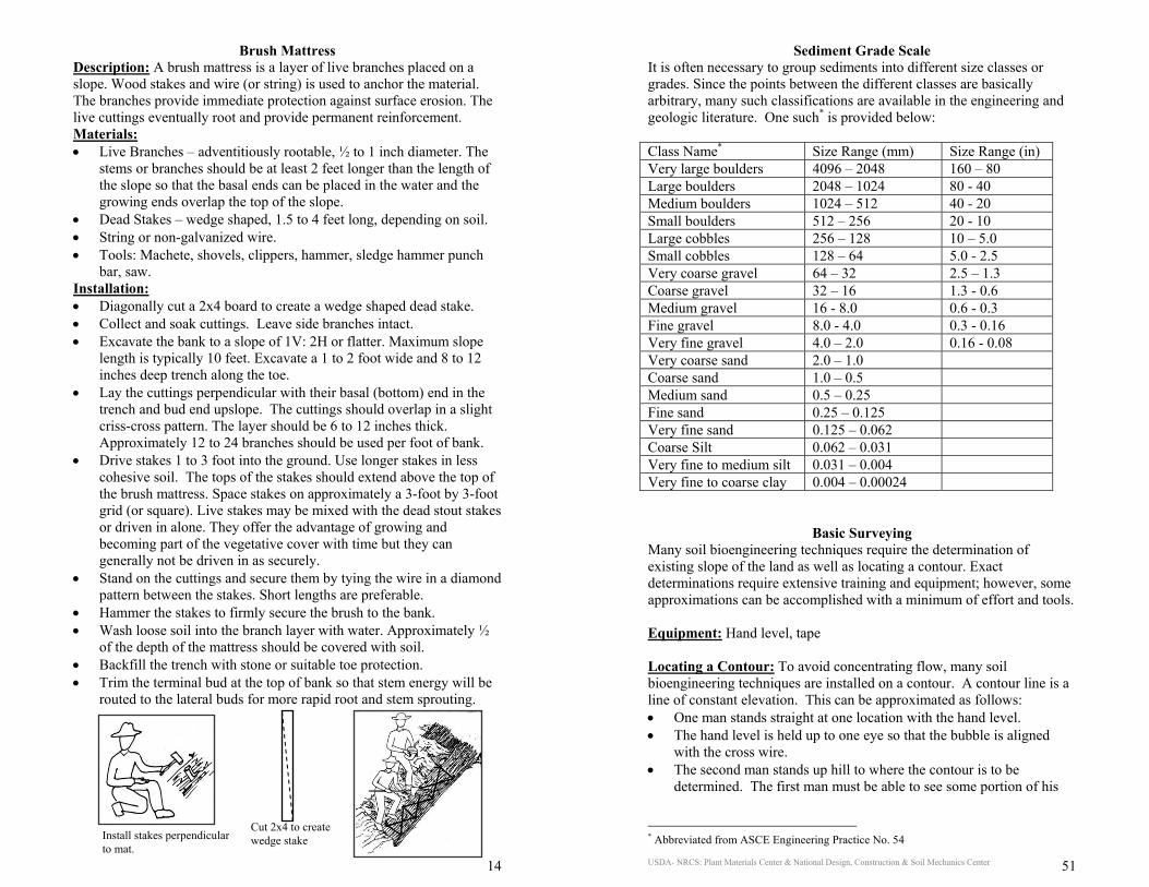
Option 2: In areas of higher stress, as can be found along the outer bank of a turn, anchor the revetment over a stone toe with soil anchors. In the detail shown below, live poles are also specified. Option 3: In areas where it is difficult to install anchor posts, the trees can be secured to large rock as shown in the detail below. The determination of the size of the rock must take into account not only the affects of the flow on the rock but also the additional stresses of the flows on the attached revetment.
Live Poles
Earth Anchors
USDA- NRCS: Plant Materials Center & National Design, Construction & Soil Mechanics Center 14
Brush Mattress Description: A brush mattress is a layer of live branches placed on a slope. Wood stakes and wire (or string) is used to anchor the material. The branches provide immediate protection against surface erosion. The live cuttings eventually root and provide permanent reinforcement. Materials: • Live Branches – adventitiously rootable, ½ to 1 inch diameter. The
stems or branches should be at least 2 feet longer than the length of the slope so that the basal ends can be placed in the water and the growing ends overlap the top of the slope.
• Dead Stakes – wedge shaped, 1.5 to 4 feet long, depending on soil. • String or non-galvanized wire. • Tools: Machete, shovels, clippers, hammer, sledge hammer punch
bar, saw. Installation: • Diagonally cut a 2x4 board to create a wedge shaped dead stake. • Collect and soak cuttings. Leave side branches intact. • Excavate the bank to a slope of 1V: 2H or flatter. Maximum slope
length is typically 10 feet. Excavate a 1 to 2 foot wide and 8 to 12 inches deep trench along the toe.
• Lay the cuttings perpendicular with their basal (bottom) end in the trench and bud end upslope. The cuttings should overlap in a slight criss-cross pattern. The layer should be 6 to 12 inches thick. Approximately 12 to 24 branches should be used per foot of bank.
• Drive stakes 1 to 3 foot into the ground. Use longer stakes in less cohesive soil. The tops of the stakes should extend above the top of the brush mattress. Space stakes on approximately a 3-foot by 3-foot grid (or square). Live stakes may be mixed with the dead stout stakes or driven in alone. They offer the advantage of growing and becoming part of the vegetative cover with time but they can generally not be driven in as securely.
• Stand on the cuttings and secure them by tying the wire in a diamond pattern between the stakes. Short lengths are preferable.
• Hammer the stakes to firmly secure the brush to the bank. • Wash loose soil into the branch layer with water. Approximately ½
of the depth of the mattress should be covered with soil. • Backfill the trench with stone or suitable toe protection. • Trim the terminal bud at the top of bank so that stem energy will be
routed to the lateral buds for more rapid root and stem sprouting.
Install stakes perpendicular to mat.
Cut 2x4 to create wedge stake
USDA- NRCS: Plant Materials Center & National Design, Construction & Soil Mechanics Center 51
Sediment Grade Scale It is often necessary to group sediments into different size classes or grades. Since the points between the different classes are basically arbitrary, many such classifications are available in the engineering and geologic literature. One such* is provided below: Class Name* Size Range (mm) Size Range (in) Very large boulders 4096 – 2048 160 – 80 Large boulders 2048 – 1024 80 - 40 Medium boulders 1024 – 512 40 - 20 Small boulders 512 – 256 20 - 10 Large cobbles 256 – 128 10 – 5.0 Small cobbles 128 – 64 5.0 - 2.5 Very coarse gravel 64 – 32 2.5 – 1.3 Coarse gravel 32 – 16 1.3 - 0.6 Medium gravel 16 - 8.0 0.6 - 0.3 Fine gravel 8.0 - 4.0 0.3 - 0.16 Very fine gravel 4.0 – 2.0 0.16 - 0.08 Very coarse sand 2.0 – 1.0 Coarse sand 1.0 – 0.5 Medium sand 0.5 – 0.25 Fine sand 0.25 – 0.125 Very fine sand 0.125 – 0.062 Coarse Silt 0.062 – 0.031 Very fine to medium silt 0.031 – 0.004 Very fine to coarse clay 0.004 – 0.00024
Basic Surveying Many soil bioengineering techniques require the determination of existing slope of the land as well as locating a contour. Exact determinations require extensive training and equipment; however, some approximations can be accomplished with a minimum of effort and tools. Equipment: Hand level, tape Locating a Contour: To avoid concentrating flow, many soil bioengineering techniques are installed on a contour. A contour line is a line of constant elevation. This can be approximated as follows: • One man stands straight at one location with the hand level. • The hand level is held up to one eye so that the bubble is aligned
with the cross wire. • The second man stands up hill to where the contour is to be
determined. The first man must be able to see some portion of his
* Abbreviated from ASCE Engineering Practice No. 54
USDA- NRCS: Plant Materials Center & National Design, Construction & Soil Mechanics Center 50
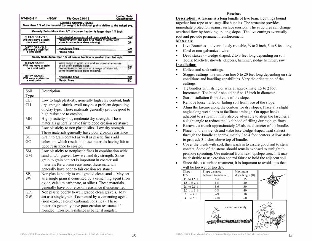
Soil Type
Description
CL, CH
Low to high plasticity, generally high clay content, high dry strength, shrink-swell may be a problem depending on clay type. These materials generally provide good to high resistance to erosion.
MH High plasticity silts, moderate dry strength. These materials generally have fair to good erosion resistance
ML Low plasticity to non plastic silts. Low dry strength. These materials generally have poor erosion resistance
SC, GC
Grain to grain contact as well as plastic fines add cohesion, which results in these materials having fair to good resistance to erosion.
SM, GM
Low plasticity to nonplastic fines in combination with sand and/or gravel. Low wet and dry strength. Since grain to grain contact is important in coarser soil materials for erosion resistance, these materials generally have poor to fair erosion resistance.
SP, SW
Non plastic poorly to well graded clean sands. May act as a single grain if cemented by a cementing agent (iron oxide, calcium carbonate, or silica). These materials generally have poor erosion resistance if uncemented.
GP, GW
Non plastic poorly to well graded clean gravels. May act as a single grain if cemented by a cementing agent (iron oxide, calcium carbonate, or silica). These materials generally have poor erosion resistance if rounded. Erosion resistance is better if angular.
USDA- NRCS: Plant Materials Center & National Design, Construction & Soil Mechanics Center 15
Fascines Description: A fascine is a long bundle of live branch cuttings bound together into rope or sausage-like bundles. The structure provides immediate protection against surface erosion. The structures can change overland flow by breaking up long slopes. The live cuttings eventually root and provide permanent reinforcement. Materials: • Live Branches – adventitiously rootable, ¾ to 2 inch, 5 to 8 feet long • Cord or non-galvanized wire • Dead stakes - - wedge shaped, 2 to 3 feet long depending on soil • Tools: Machete, shovels, clippers, hammer, sledge hammer, saw Installation: • Collect and soak cuttings. • Stagger cuttings in a uniform line 5 to 20 feet long depending on site
conditions and handling capabilities. Vary the orientation of the cuttings.
• Tie bundles with string or wire at approximate 1.5 to 2 foot increments. The bundle should be 6 to 12 inch in diameter.
• Start installation from the toe of the slope. • Remove loose, failed or failing soil from face of the slope. • Align the fascine along the contour for dry slopes. Place at a slight
angle along wet slopes to facilitate drainage. On upper banks adjacent to a stream, it may also be advisable to align the fascines at a slight angle to reduce the likelihood of rilling during high flows.
• Excavate a trench approximately 2/3rds the diameter of the bundle. • Place bundle in trench and stake (use wedge shaped dead stakes)
through the bundle at approximately 2 to 4 foot centers. Allow stake to protrude 3 inches above top of bundle.
• Cover the brush with soil, then wash in to assure good soil to stem contact. Some of the stems should remain exposed to sunlight to promote sprouting. Use material from next, upslope trench. It may be desirable to use erosion control fabric to hold the adjacent soil.
• Since this is a surface treatment, it is important to avoid sites that will be too wet or too dry. Slope H:V
Slope distance between trenches (ft)
Maximum slope length (ft)
1:1 to 1.5:1 3-4 15 1.5:1 to 2:1 4-5 20 2:1 to 2.5:1 5-6 30 2.5:1 to 3:1 6-8 40 3:1 to 4:1 8-9 50 4:1 to 5:1 9-10 60
Fascine Assembly
USDA- NRCS: Plant Materials Center & National Design, Construction & Soil Mechanics Center 16
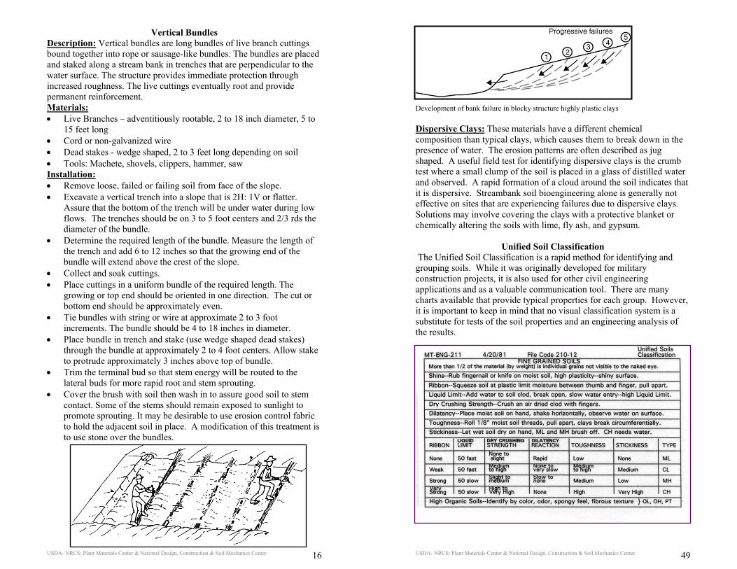
Vertical Bundles Description: Vertical bundles are long bundles of live branch cuttings bound together into rope or sausage-like bundles. The bundles are placed and staked along a stream bank in trenches that are perpendicular to the water surface. The structure provides immediate protection through increased roughness. The live cuttings eventually root and provide permanent reinforcement. Materials: • Live Branches – adventitiously rootable, 2 to 18 inch diameter, 5 to
15 feet long • Cord or non-galvanized wire • Dead stakes - wedge shaped, 2 to 3 feet long depending on soil • Tools: Machete, shovels, clippers, hammer, saw Installation: • Remove loose, failed or failing soil from face of the slope. • Excavate a vertical trench into a slope that is 2H: 1V or flatter.
Assure that the bottom of the trench will be under water during low flows. The trenches should be on 3 to 5 foot centers and 2/3 rds the diameter of the bundle.
• Determine the required length of the bundle. Measure the length of the trench and add 6 to 12 inches so that the growing end of the bundle will extend above the crest of the slope.
• Collect and soak cuttings. • Place cuttings in a uniform bundle of the required length. The
growing or top end should be oriented in one direction. The cut or bottom end should be approximately even.
• Tie bundles with string or wire at approximate 2 to 3 foot increments. The bundle should be 4 to 18 inches in diameter.
• Place bundle in trench and stake (use wedge shaped dead stakes) through the bundle at approximately 2 to 4 foot centers. Allow stake to protrude approximately 3 inches above top of bundle.
• Trim the terminal bud so that stem energy will be routed to the lateral buds for more rapid root and stem sprouting.
• Cover the brush with soil then wash in to assure good soil to stem contact. Some of the stems should remain exposed to sunlight to promote sprouting. It may be desirable to use erosion control fabric to hold the adjacent soil in place. A modification of this treatment is to use stone over the bundles.
USDA- NRCS: Plant Materials Center & National Design, Construction & Soil Mechanics Center 49
Development of bank failure in blocky structure highly plastic clays Dispersive Clays: These materials have a different chemical composition than typical clays, which causes them to break down in the presence of water. The erosion patterns are often described as jug shaped. A useful field test for identifying dispersive clays is the crumb test where a small clump of the soil is placed in a glass of distilled water and observed. A rapid formation of a cloud around the soil indicates that it is dispersive. Streambank soil bioengineering alone is generally not effective on sites that are experiencing failures due to dispersive clays. Solutions may involve covering the clays with a protective blanket or chemically altering the soils with lime, fly ash, and gypsum.
Unified Soil Classification The Unified Soil Classification is a rapid method for identifying and grouping soils. While it was originally developed for military construction projects, it is also used for other civil engineering applications and as a valuable communication tool. There are many charts available that provide typical properties for each group. However, it is important to keep in mind that no visual classification system is a substitute for tests of the soil properties and an engineering analysis of the results.
USDA- NRCS: Plant Materials Center & National Design, Construction & Soil Mechanics Center 48
Soil Mechanics Considerations
Many channel stability problems result from a combination and interaction of a number of different causes*. These causes can include not only issues related to fluvial erosive forces, but also seepage problems as well as properties of the soil. Three common geotechnical stability problems are briefly outlined below. Piping/Sapping of Channel Banks: May occur where silts and sands are layered between lower permeability clays. Water flowing from the bank can detach the cohesionless soil particles and carry them out of the channel bank leaving a void that may be pipe or shelf shaped. The overlying soils then fail by toppling into the channel. The slope failure that results is called an infinite slope failure. Streambank soil bioengineering measures alone are generally ineffective in preventing a piping/sapping failure from occurring. However, streambank soil bioengineering may be effective in stabilizing the upper and lower banks after a suitable filter layer or drain is installed and after the bank has been graded to a stable slope. Development of piping/sapping bank failure Shallow Slope Failure in Block Structure and Highly Plastic Clays: The blocky structure in these types of materials generally results from alternating wetting and drying cycles. The soil structure is further weakened when water enters these cracks and lubricates them. Bank failures are generally arc shaped and occur in successive incidences of slope movement. The slides are generally no more than 3 to 4 feet deep. The ultimate stable slope can be in the range of 4H:1V to 7H:1V. Solutions to a stability problem of this nature may involve replacing the highly plastic soil, soil reinforcement, and shaping the bank. Streambank soil bioengineering alone is of limited benefit.
* Adapted from material provided by Danny McCook, Geotechnical Civil Engineer, NDCSMC
USDA- NRCS: Plant Materials Center & National Design, Construction & Soil Mechanics Center 17
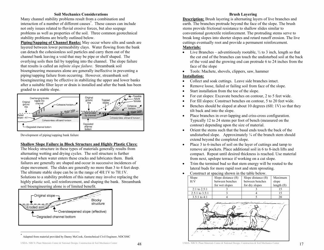
Brush Layering Description: Brush layering is alternating layers of live branches and earth. The branches protrude beyond the face of the slope. The brush stems provide frictional resistance to shallow slides similar to conventional geotextile reinforcement. The protruding stems serve to break long slopes into shorter slopes and retard runoff erosion. The live cuttings eventually root and provide a permanent reinforcement. Materials: • Live Branches – adventitiously rootable, ½ to 3 inch, length so that
the cut end of the branches can touch the undisturbed soil at the back of the void and the growing end can protrude 6 to 24 inches from the face of the slope
• Tools: Machete, shovels, clippers, saw, hammer Installation: • Collect and soak cuttings. Leave side branches intact. • Remove loose, failed or failing soil from face of the slope. • Start installation from the toe of the slope. • For cut slopes: Excavate benches on contour, 2 to 5 feet wide. • For fill slopes: Construct benches on contour, 5 to 20 feet wide. • Benches should be sloped at about 10 degrees (6H: 1V) so that they
tilt back and into the slope. • Place branches in over-lapping and criss-cross configuration.
Typically 12 to 24 stems per foot of bench (measured on the contour) depending upon the size of material.
• Orient the stems such that the basal ends touch the back of the undisturbed slope. Approximately ¼ of the branch stem should extend beyond the completed slope.
• Place 3 to 6-inches of soil on the layer of cuttings and tamp to remove air pockets. Place additional soil in 6 to 8-inch lifts and compact. Repeat until desired thickness is reached. Use material from next, upslope terrace if working on a cut slope.
• Trim the terminal bud so that stem energy will be routed to the lateral buds for more rapid root and stem sprouting.
• Construct at spacing shown in the table below. Slope H:V
Slope distance (ft) between benches for wet slopes
Slope distance (ft) between benches for dry slopes
Maximum slope length (ft)
2:1 to 2.5:1 3 3 15 2.5:1 to 3.5:1 3 4 15 3.5:1 to 4:1 4 5 20
USDA- NRCS: Plant Materials Center & National Design, Construction & Soil Mechanics Center 18
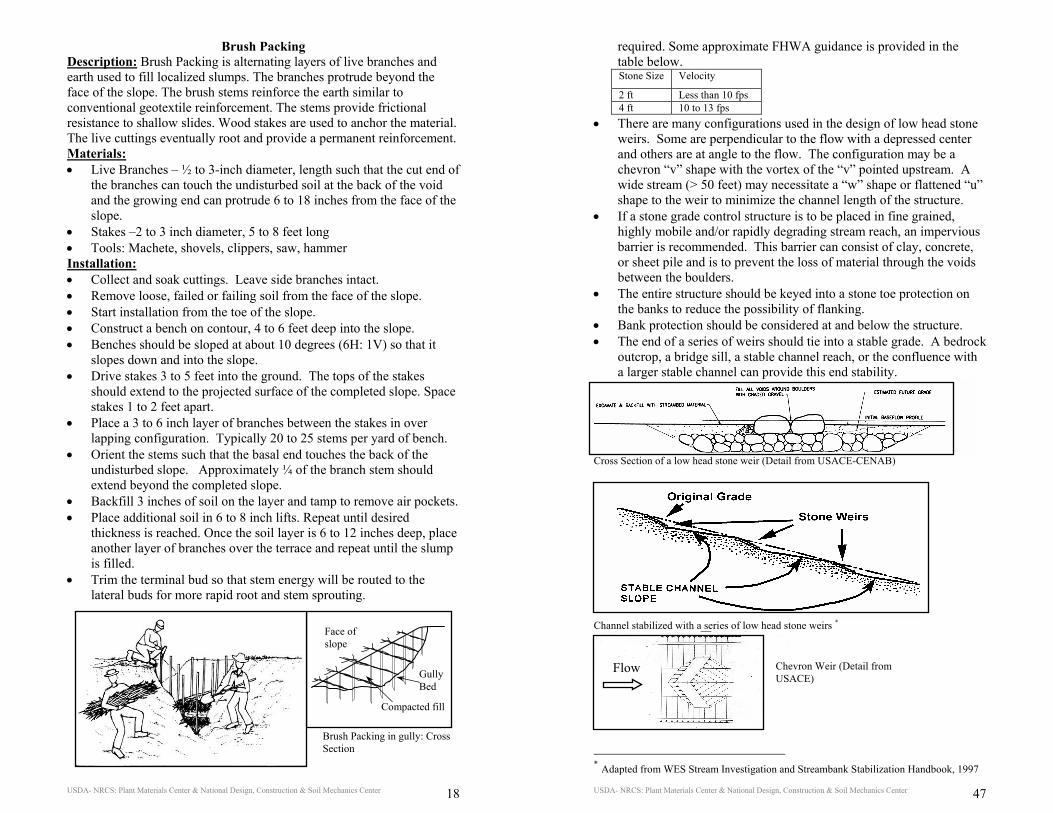
Brush Packing Description: Brush Packing is alternating layers of live branches and earth used to fill localized slumps. The branches protrude beyond the face of the slope. The brush stems reinforce the earth similar to conventional geotextile reinforcement. The stems provide frictional resistance to shallow slides. Wood stakes are used to anchor the material. The live cuttings eventually root and provide a permanent reinforcement. Materials: • Live Branches – ½ to 3-inch diameter, length such that the cut end of
the branches can touch the undisturbed soil at the back of the void and the growing end can protrude 6 to 18 inches from the face of the slope.
• Stakes –2 to 3 inch diameter, 5 to 8 feet long • Tools: Machete, shovels, clippers, saw, hammer Installation: • Collect and soak cuttings. Leave side branches intact. • Remove loose, failed or failing soil from the face of the slope. • Start installation from the toe of the slope. • Construct a bench on contour, 4 to 6 feet deep into the slope. • Benches should be sloped at about 10 degrees (6H: 1V) so that it
slopes down and into the slope. • Drive stakes 3 to 5 feet into the ground. The tops of the stakes
should extend to the projected surface of the completed slope. Space stakes 1 to 2 feet apart.
• Place a 3 to 6 inch layer of branches between the stakes in over lapping configuration. Typically 20 to 25 stems per yard of bench.
• Orient the stems such that the basal end touches the back of the undisturbed slope. Approximately ¼ of the branch stem should extend beyond the completed slope.
• Backfill 3 inches of soil on the layer and tamp to remove air pockets. • Place additional soil in 6 to 8 inch lifts. Repeat until desired
thickness is reached. Once the soil layer is 6 to 12 inches deep, place another layer of branches over the terrace and repeat until the slump is filled.
• Trim the terminal bud so that stem energy will be routed to the lateral buds for more rapid root and stem sprouting.
Brush Packing in gully: Cross Section
Face of slope
Gully Bed
Compacted fill
USDA- NRCS: Plant Materials Center & National Design, Construction & Soil Mechanics Center 47
required. Some approximate FHWA guidance is provided in the table below. Stone Size Velocity
2 ft Less than 10 fps 4 ft 10 to 13 fps
• There are many configurations used in the design of low head stone weirs. Some are perpendicular to the flow with a depressed center and others are at angle to the flow. The configuration may be a chevron “v” shape with the vortex of the “v” pointed upstream. A wide stream (> 50 feet) may necessitate a “w” shape or flattened “u” shape to the weir to minimize the channel length of the structure.
• If a stone grade control structure is to be placed in fine grained, highly mobile and/or rapidly degrading stream reach, an impervious barrier is recommended. This barrier can consist of clay, concrete, or sheet pile and is to prevent the loss of material through the voids between the boulders.
• The entire structure should be keyed into a stone toe protection on the banks to reduce the possibility of flanking.
• Bank protection should be considered at and below the structure. • The end of a series of weirs should tie into a stable grade. A bedrock
outcrop, a bridge sill, a stable channel reach, or the confluence with a larger stable channel can provide this end stability.
Cross Section of a low head stone weir (Detail from USACE-CENAB)
Channel stabilized with a series of low head stone weirs *
* Adapted from WES Stream Investigation and Streambank Stabilization Handbook, 1997
Chevron Weir (Detail from USACE)
Flow
USDA- NRCS: Plant Materials Center & National Design, Construction & Soil Mechanics Center 46
Low Head Stone Grade Control Weirs Description: Low Head Stone Grade Control Weirs are structures designed to maintain the grade of the stream and typically require an engineered design. They are used to stop headcutting, reduce upstream energy, and to prevent bed scour. The establishment of a stable grade in an eroding stream is a critical first step in any stream bank stabilization or restoration effort. Low head stone weirs are typically used in moderate to steep gradient, gravel bed streams. They are not typically used in streams that are subject to braiding or aggradation. Additional cautions include: • Impacts to flood flows should be considered. • Changes to the existing profile should be minimized. • The grade at the lower end of a series of stone weirs should be stable
or should be stabilized. • Caution should be exercised in reaches with a high debris load since
the material may build up on the weir stones. • Aggradation upstream of any grade control may cause stream
meandering. Design and Installation: • The stone weirs should be located to correspond, as much as
possible, to existing riffles and shallow areas. Avoid locating them in deep pools.
• The spacing between the weirs should be calculated. One of the techniques for locating the weirs includes the use of a limiting slope criteria to estimate the minimum spacing as follows:
Where: x = length between grade control structures H = amount of drop removed in reach between the weirs So = original bed slope SL = limiting slope
The limiting slope can be calculated or approximated as 0.5 the bed slope in steep streams and 0.7 the bed slope in mild gradient streams. Alternately, the toe of the next upstream grade control can be placed at the same elevation as the crest of the downstream grade control. • The maximum total drop across the length of riffle that a stone weir
can maintain is typically one foot. • To control the development of this scour hole so that it does not
undermine the stones of the weir, a blanket of riprap or graded stone should be provided as bedding and backfill under and around the weir stones. The bedding should extend several feet beyond the boulders.
• Since the stones must be designed for impinging flow, they should be large. It is important to note that most of the common riprap design guidance techniques are for revetments and must be adjusted to reflect impinging flow. Detailed engineering analysis is typically
Lo SSHx−
=
USDA- NRCS: Plant Materials Center & National Design, Construction & Soil Mechanics Center 19
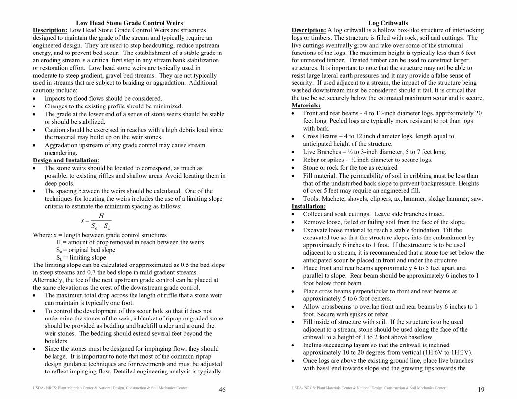
Log Cribwalls Description: A log cribwall is a hollow box-like structure of interlocking logs or timbers. The structure is filled with rock, soil and cuttings. The live cuttings eventually grow and take over some of the structural functions of the logs. The maximum height is typically less than 6 feet for untreated timber. Treated timber can be used to construct larger structures. It is important to note that the structure may not be able to resist large lateral earth pressures and it may provide a false sense of security. If used adjacent to a stream, the impact of the structure being washed downstream must be considered should it fail. It is critical that the toe be set securely below the estimated maximum scour and is secure. Materials: • Front and rear beams - 4 to 12-inch diameter logs, approximately 20
feet long. Peeled logs are typically more resistant to rot than logs with bark.
• Cross Beams – 4 to 12 inch diameter logs, length equal to anticipated height of the structure.
• Live Branches – ½ to 3-inch diameter, 5 to 7 feet long. • Rebar or spikes - ½ inch diameter to secure logs. • Stone or rock for the toe as required • Fill material. The permeability of soil in cribbing must be less than
that of the undisturbed back slope to prevent backpressure. Heights of over 5 feet may require an engineered fill.
• Tools: Machete, shovels, clippers, ax, hammer, sledge hammer, saw. Installation: • Collect and soak cuttings. Leave side branches intact. • Remove loose, failed or failing soil from the face of the slope. • Excavate loose material to reach a stable foundation. Tilt the
excavated toe so that the structure slopes into the embankment by approximately 6 inches to 1 foot. If the structure is to be used adjacent to a stream, it is recommended that a stone toe set below the anticipated scour be placed in front and under the structure.
• Place front and rear beams approximately 4 to 5 feet apart and parallel to slope. Rear beam should be approximately 6 inches to 1 foot below front beam.
• Place cross beams perpendicular to front and rear beams at approximately 5 to 6 foot centers.
• Allow crossbeams to overlap front and rear beams by 6 inches to 1 foot. Secure with spikes or rebar.
• Fill inside of structure with soil. If the structure is to be used adjacent to a stream, stone should be used along the face of the cribwall to a height of 1 to 2 foot above baseflow.
• Incline succeeding layers so that the cribwall is inclined approximately 10 to 20 degrees from vertical (1H:6V to 1H:3V).
• Once logs are above the existing ground line, place live branches with basal end towards slope and the growing tips towards the
USDA- NRCS: Plant Materials Center & National Design, Construction & Soil Mechanics Center 20
outside. Allow bud ends to extend beyond front and rear cross beams by approximately 1 foot.
• Align live branches so that they extend on top of the front cross beam and below the rear cross beam for a given course.
• Trim the terminal bud so that stem energy will be routed to the lateral buds for more rapid root and stem sprouting.
Cross Section of a vegetated crib wall. Note that in this case, brush layering and live staking treatments are specified above the structure. Logs have also been used for habitat enhancement and as erosion stops in dry channels and ditches. Note in the figure below that the logs should be keyed into the bank and that the structure does not fill the channel. Also note that an energy dissipation apron is typically keyed into the bed below the structure. The minimum length of this apron is typically 2 times the height of the structure
USDA- NRCS: Plant Materials Center & National Design, Construction & Soil Mechanics Center 45
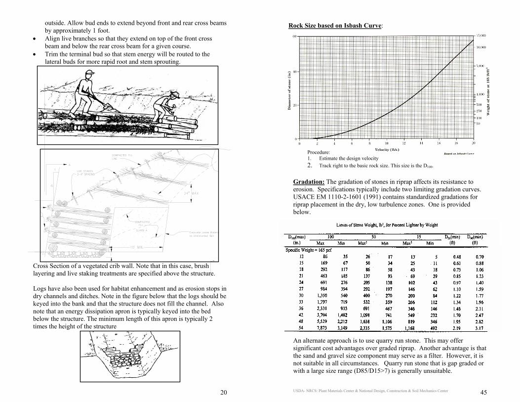
Gradation: The gradation of stones in riprap affects its resistance to erosion. Specifications typically include two limiting gradation curves. USACE EM 1110-2-1601 (1991) contains standardized gradations for riprap placement in the dry, low turbulence zones. One is provided below. An alternate approach is to use quarry run stone. This may offer significant cost advantages over graded riprap. Another advantage is that the sand and gravel size component may serve as a filter. However, it is not suitable in all circumstances. Quarry run stone that is gap graded or with a large size range (D85/D15>7) is generally unsuitable.
Rock Size based on Isbash Curve:
Procedure: 1. Estimate the design velocity 2. Track right to the basic rock size. This size is the D100.
USDA- NRCS: Plant Materials Center & National Design, Construction & Soil Mechanics Center 44
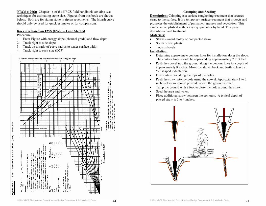
NRCS (1996): Chapter 16 of the NRCS field handbook contains two techniques for estimating stone size. Figures from this book are shown below. Both are for sizing stone in riprap revetments. The Isbash curve should only be used for quick estimates or for comparisons. Rock size based on FWS (FWS) – Lane Method. Procedure: 1. Enter Figure with energy slope (channel grade) and flow depth. 2. Track right to side slope 3. Track up to ratio of curve radius to water surface width 4. Track right to rock size (D75)
USDA- NRCS: Plant Materials Center & National Design, Construction & Soil Mechanics Center 21
Crimping and Seeding Description: Crimping is a surface roughening treatment that secures straw to the surface. It is a temporary surface treatment that protects and promotes the establishment of permanent grasses and vegetation. This can be accomplished with heavy equipment or by hand. This page describes a hand treatment. Materials: • Straw – avoid moldy or compacted straw. • Seeds or live plants. • Tools: shovels Installation: • Determine approximate contour lines for installation along the slope.
The contour lines should be separated by approximately 2 to 3 feet. • Push the shovel into the ground along the contour lines to a depth of
approximately 8 inches. Move the shovel back and forth to leave a ‘V’ shaped indentation.
• Distribute straw along the tops of the holes. • Push the straw into the hole using the shovel. Approximately 1 to 3
inches of straw should protrude above the ground surface. • Tamp the ground with a foot to close the hole around the straw. • Seed the area and water. • Place additional straw between the contours. A typical depth of
placed straw is 2 to 4 inches.
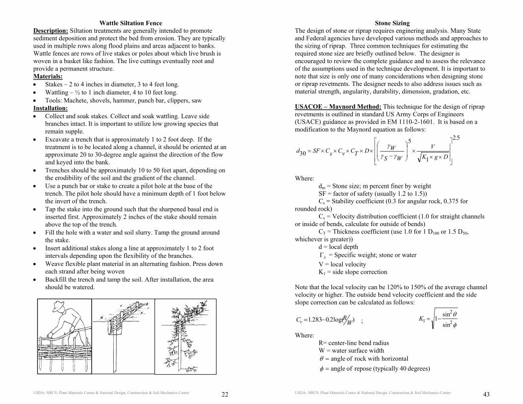
USDA- NRCS: Plant Materials Center & National Design, Construction & Soil Mechanics Center 22
Wattle Siltation Fence Description: Siltation treatments are generally intended to promote sediment deposition and protect the bed from erosion. They are typically used in multiple rows along flood plains and areas adjacent to banks. Wattle fences are rows of live stakes or poles about which live brush is woven in a basket like fashion. The live cuttings eventually root and provide a permanent structure. Materials: • Stakes – 2 to 4 inches in diameter, 3 to 4 feet long. • Wattling – ½ to 1 inch diameter, 4 to 10 feet long. • Tools: Machete, shovels, hammer, punch bar, clippers, saw Installation: • Collect and soak stakes. Collect and soak wattling. Leave side
branches intact. It is important to utilize low growing species that remain supple.
• Excavate a trench that is approximately 1 to 2 foot deep. If the treatment is to be located along a channel, it should be oriented at an approximate 20 to 30-degree angle against the direction of the flow and keyed into the bank.
• Trenches should be approximately 10 to 50 feet apart, depending on the erodibility of the soil and the gradient of the channel.
• Use a punch bar or stake to create a pilot hole at the base of the trench. The pilot hole should have a minimum depth of 1 foot below the invert of the trench.
• Tap the stake into the ground such that the sharpened basal end is inserted first. Approximately 2 inches of the stake should remain above the top of the trench.
• Fill the hole with a water and soil slurry. Tamp the ground around the stake.
• Insert additional stakes along a line at approximately 1 to 2 foot intervals depending upon the flexibility of the branches.
• Weave flexible plant material in an alternating fashion. Press down each strand after being woven
• Backfill the trench and tamp the soil. After installation, the area should be watered.
USDA- NRCS: Plant Materials Center & National Design, Construction & Soil Mechanics Center 43
Stone Sizing The design of stone or riprap requires enginering analysis. Many State and Federal agencies have developed various methods and approaches to the sizing of riprap. Three common techniques for estimating the required stone size are briefly outlined below. The designer is encouraged to review the complete guidance and to assess the relevance of the assumptions used in the technique development. It is important to note that size is only one of many conciderations when designing stone or riprap revetments. The designer needs to also address issues such as material strength, angularity, durability, dimension, gradation, etc. USACOE – Maynord Method: This technique for the design of riprap revetments is outlined in standard US Army Corps of Engineers (USACE) guidance as provided in EM 1110-2-1601. It is based on a modification to the Maynord equation as follows:
52
1
5
30
.
DgKV
.
WS
WDTCvCsCSFd
×××
−×××××=
γγ
γ
Where: dm = Stone size; m percent finer by weight SF = factor of safety (usually 1.2 to 1.5)) Cs = Stability coefficient (0.3 for angular rock, 0.375 for rounded rock) Cv = Velocity distribution coefficient (1.0 for straight channels or inside of bends, calculate for outside of bends) CT = Thickness coefficient (use 1.0 for 1 D100 or 1.5 D50, whichever is greater)) d = local depth Γx = Specific weight; stone or water V = local velocity K1 = side slope correction Note that the local velocity can be 120% to 150% of the average channel velocity or higher. The outside bend velocity coefficient and the side slope correction can be calculated as follows:
)log(2.0283.1 WRCv −= ; φ
θ2
2
1sinsin1−=K
Where: R= center-line bend radius W = water surface width
degrees) 40 (typically repose of angle horizontalrock with of angle
==
φθ
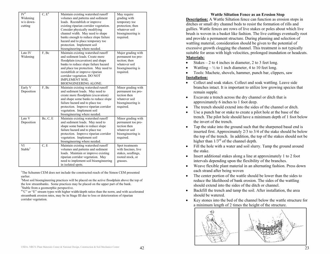
USDA- NRCS: Plant Materials Center & National Design, Construction & Soil Mechanics Center 42
IV4 Widening w/o down-cutting
C, E4 Maintain existing watershed runoff volumes and patterns and sediment loads. Reestablish or improve existing riparian corridor vegetation. Consider physically modifying channel width. May need to shape banks enough to reduce slope failure hazard and to place temporary toe protection. Implement soil bioengineering where needed.
May require grading with temporary toe protection; then whatever soil bioengineering is required.
Late IV Widening
F, Bc Maintain existing watershed runoff and sediment loads. Create more floodplain (excavation) and shape banks to reduce slope failure hazard and place toe protection. May need to reestablish or improve riparian corridor vegetation. DO NOT IMPLEMENT SOIL BIOENGINEERING ALONE.
Major grading with permanent toe pro- tection; then whatever soil bioengineering is required.
Early V Deposition
F, Bc Maintain existing watershed runoff and sediment loads. May need to create more floodplain (excavation) and shape some banks to reduce slope failure hazard and to place toe protection. Improve riparian corridor vegetation. Implement soil bioengineering where needed.
Minor grading with permanent toe pro- tection then whatever soil bioengineering is required.
Late V Deposition
Bc, C, E Maintain existing watershed runoff and sediment loads. May need to shape some banks to reduce slope failure hazard and to place toe protection. Improve riparian corridor vegetation. Implement soil bioengineering where needed.
Minor grading with permanent toe pro- tection then whatever soil bioengineering is required.
VI Stable3
C, E Maintain existing watershed runoff volumes and patterns and sediment loads. Maintain or improve existing riparian corridor vegetation. May need to implement soil bioengineering in isolated spots.
Spot treatments with fascines, live stakes, seedlings, rooted stock, or grasses.
1The Schumm CEM does not include the constructed reach of the Simon CEM presented earlier. 2Most soil bioengineering practices will be placed on the active floodplain above the top of the low streambanks. Some practices may be placed on the upper part of the bank. 3Stable from a geomorphic perspective. 4”C” or “E” stream types with higher width/depth ratios than the norm, and with accelerated streambank erosion rates, may be in Stage III due to loss or deterioration of riparian corridor vegetation.
USDA- NRCS: Plant Materials Center & National Design, Construction & Soil Mechanics Center 23
Wattle Siltation Fence as an Erosion Stop Description: A Wattle Siltation fence can function as erosion stops in ditches or small dry channel beds to resist the formation of rills and gullies. Wattle fences are rows of live stakes or poles about which live brush is woven in a basket like fashion. The live cuttings eventually root and provide a permanent structure. During planning and selection of wattling material, consideration should be given to the potential of excessive growth clogging the channel. This treatment is not typically suitable for areas with high velocities, prolonged inundation or headcuts. Materials: • Stakes – 2 to 4 inches in diameter, 2 to 3 feet long. • Wattling – ½ to 1 inch diameter, 4 to 10 feet long. • Tools: Machete, shovels, hammer, punch bar, clippers, saw Installation: • Collect and soak stakes. Collect and soak wattling. Leave side
branches intact. It is important to utilize low growing species that remain supple.
• Excavate a trench across the dry channel or ditch that is approximately 6 inches to 1 foot deep.
• The trench should extend into the sides of the channel or ditch. • Use a punch bar or stake to create a pilot hole at the base of the
trench. The pilot hole should have a minimum depth of 1 foot below the invert of the trench.
• Tap the stake into the ground such that the sharpened basal end is inserted first. Approximately 2/3 to 3/4 of the stake should be below the top of the trench. In addition, the top of the stakes should not be higher than 1/3rd of the channel depth.
• Fill the hole with a water and soil slurry. Tamp the ground around the stake.
• Insert additional stakes along a line at approximately 1 to 2 foot intervals depending upon the flexibility of the branches.
• Weave flexible plant material in an alternating fashion. Press down each strand after being woven
• The center portion of the wattle should be lower than the sides to reduce the likelihood of bank erosion. The sides of the wattling should extend into the sides of the ditch or channel.
• Backfill the trench and tamp the soil. After installation, the area should be watered.
• Key stones into the bed of the channel below the wattle structure for a minimum length of 2 times the height of the structure.
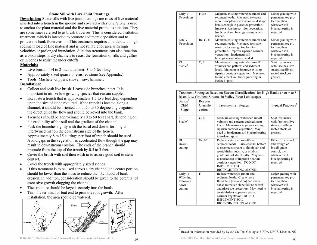
USDA- NRCS: Plant Materials Center & National Design, Construction & Soil Mechanics Center 24
Stone Sill with Live Joint Plantings Description: Stone sills with live joint plantings are rows of live material inserted into a trench in the ground and covered with stone. Stone is used to anchor the plant material and the live material promotes siltation. They are sometimes referred to as brush traverses. This is considered a siltation treatment, which is intended to promote sediment deposition and to protect the bank from erosion. This treatment requires a moderate to high sediment load of fine material and is not suitable for area with high velocities or prolonged inundation. Siltation treatments can also function as erosion stops in dry channels to resist the formation of rills and gullies or in bends to resist meander cutoffs. Materials: • Live brush - 1/4 to 2-inch diameter, 3 to 6 feet long. • Appropriately sized quarry or crushed stone (see Appendix). • Tools: Machete, clippers, shovel, saw, hammer. Installation: • Collect and soak live brush. Leave side branches intact. It is
important to utilize low growing species that remain supple. • Excavate a trench that is approximately 1.5 to 3 feet deep depending
upon the size of stone required. If the trench is located along a channel, it should be oriented about 20 to 30-degree angle against the direction of the flow and should be keyed into the bank.
• Trenches should be approximately 10 to 50 feet apart, depending on the erodibility of the soil and the gradient of the channel.
• Pack the branches tightly with the basal end down, forming an intertwined mat on the downstream side of the trench. Approximately 8 to 15 cuttings per foot of trench should be used. Avoid gaps in the vegetation as accelerated flow though the gap may result in downstream erosion. The ends of the branch should protrude from the top of the trench by 0.5 to 3 feet.
• Cover the brush with soil then wash in to assure good soil to stem contact.
• Cover the trench with appropriately sized stones. • If this treatment is to be used across a dry channel, the center portion
should be lower than the sides to reduce the likelihood of bank erosion. In addition, consideration should be given to the potential of excessive growth clogging the channel.
• The structure should be keyed securely into the bank. • Trim the terminal or bud end to promote root growth. After
installation, the area should be watered.
Flow
USDA- NRCS: Plant Materials Center & National Design, Construction & Soil Mechanics Center 41
Early V Deposition
F, Bc Maintain existing watershed runoff and sediment loads. May need to create more floodplain (excavation) and shape banks enough to place toe protection. Improve riparian corridor vegetation. Implement soil bioengineering where needed.
Minor grading with permanent toe pro- tection; then whatever soil bioengineering is required.
Late V Deposition
Bc, C, E Maintain existing watershed runoff and sediment loads. May need to shape some banks enough to place toe protection. Improve riparian corridor vegetation. Implement soil bioengineering where needed.
Minor grading with permanent toe pro- tection; then whatever soil bioengineering is required.
VI Stable2
C, E Maintain existing watershed runoff volumes and patterns and sediment loads. Maintain or improve existing riparian corridor vegetation. May need to implement soil bioengineering in isolated spots.
Spot treatments with fascines, live stakes, seedlings, rooted stock, or grasses.
Treatment Strategies Based on Stream Classification* for High Banks (> or = to 8 ft) on Low Gradient Streams in Valley Floor Landscapes Simon1 CEM Stage
Rosgen Classifi-cation
Treatment Strategies
Typical Practices2
I Stable3
C, E Maintain existing watershed runoff volumes and patterns and sediment loads. Maintain or improve existing riparian corridor vegetation. May need to implement soil bioengineering in isolated spots.
Spot treatments with fascines, live stakes, seedlings, rooted stock, or grasses.
III Down-cutting
Gc, F? Reduce watershed runoff and sediment loads. Raise channel bottom to reconnect stream to floodplain and reestablish sinuosity, or establish grade control structurally. May need to reestablish or improve riparian corridor vegetation. DO NOT IMPLEMENT SOIL BIOENGINEERING ALONE.
Either fill channel and realign or install grade control; then whatever soil bioengineering is required.
Early IV Widening following down-cutting
F Reduce watershed runoff and sediment loads. Create more floodplain (excavation) and shape banks to reduce slope failure hazard and place toe protection. May need to reestablish or improve riparian corridor vegetation. DO NOT IMPLEMENT SOIL BIOENGINEERING ALONE.
Major grading with permanent toe pro- tection; then whatever soil bioengineering is required.
* Based on information provided by Lyle J. Steffen, Geologist, USDA-NRCS, Lincoln, NE
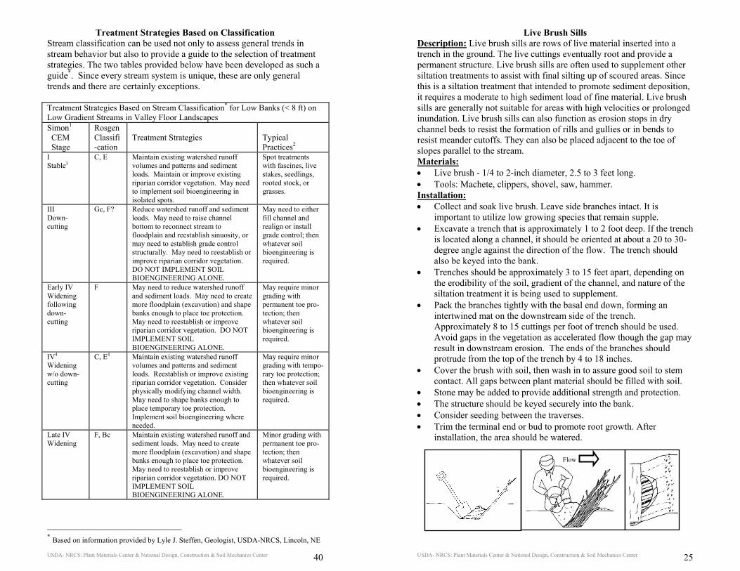
USDA- NRCS: Plant Materials Center & National Design, Construction & Soil Mechanics Center 40
Treatment Strategies Based on Classification Stream classification can be used not only to assess general trends in stream behavior but also to provide a guide to the selection of treatment strategies. The two tables provided below have been developed as such a guide*. Since every stream system is unique, these are only general trends and there are certainly exceptions. Treatment Strategies Based on Stream Classification* for Low Banks (< 8 ft) on Low Gradient Streams in Valley Floor Landscapes Simon1 CEM Stage
Rosgen Classifi-cation
Treatment Strategies
Typical Practices2
I Stable3
C, E Maintain existing watershed runoff volumes and patterns and sediment loads. Maintain or improve existing riparian corridor vegetation. May need to implement soil bioengineering in isolated spots.
Spot treatments with fascines, live stakes, seedlings, rooted stock, or grasses.
III Down-cutting
Gc, F? Reduce watershed runoff and sediment loads. May need to raise channel bottom to reconnect stream to floodplain and reestablish sinuosity, or may need to establish grade control structurally. May need to reestablish or improve riparian corridor vegetation. DO NOT IMPLEMENT SOIL BIOENGINEERING ALONE.
May need to either fill channel and realign or install grade control; then whatever soil bioengineering is required.
Early IV Widening following down-cutting
F May need to reduce watershed runoff and sediment loads. May need to create more floodplain (excavation) and shape banks enough to place toe protection. May need to reestablish or improve riparian corridor vegetation. DO NOT IMPLEMENT SOIL BIOENGINEERING ALONE.
May require minor grading with permanent toe pro- tection; then whatever soil bioengineering is required.
IV4 Widening w/o down-cutting
C, E4 Maintain existing watershed runoff volumes and patterns and sediment loads. Reestablish or improve existing riparian corridor vegetation. Consider physically modifying channel width. May need to shape banks enough to place temporary toe protection. Implement soil bioengineering where needed.
May require minor grading with tempo-rary toe protection; then whatever soil bioengineering is required.
Late IV Widening
F, Bc Maintain existing watershed runoff and sediment loads. May need to create more floodplain (excavation) and shape banks enough to place toe protection. May need to reestablish or improve riparian corridor vegetation. DO NOT IMPLEMENT SOIL BIOENGINEERING ALONE.
Minor grading with permanent toe pro- tection; then whatever soil bioengineering is required.
* Based on information provided by Lyle J. Steffen, Geologist, USDA-NRCS, Lincoln, NE
USDA- NRCS: Plant Materials Center & National Design, Construction & Soil Mechanics Center 25
Live Brush Sills Description: Live brush sills are rows of live material inserted into a trench in the ground. The live cuttings eventually root and provide a permanent structure. Live brush sills are often used to supplement other siltation treatments to assist with final silting up of scoured areas. Since this is a siltation treatment that intended to promote sediment deposition, it requires a moderate to high sediment load of fine material. Live brush sills are generally not suitable for areas with high velocities or prolonged inundation. Live brush sills can also function as erosion stops in dry channel beds to resist the formation of rills and gullies or in bends to resist meander cutoffs. They can also be placed adjacent to the toe of slopes parallel to the stream. Materials: • Live brush - 1/4 to 2-inch diameter, 2.5 to 3 feet long. • Tools: Machete, clippers, shovel, saw, hammer. Installation: • Collect and soak live brush. Leave side branches intact. It is
important to utilize low growing species that remain supple. • Excavate a trench that is approximately 1 to 2 foot deep. If the trench
is located along a channel, it should be oriented at about a 20 to 30-degree angle against the direction of the flow. The trench should also be keyed into the bank.
• Trenches should be approximately 3 to 15 feet apart, depending on the erodibility of the soil, gradient of the channel, and nature of the siltation treatment it is being used to supplement.
• Pack the branches tightly with the basal end down, forming an intertwined mat on the downstream side of the trench. Approximately 8 to 15 cuttings per foot of trench should be used. Avoid gaps in the vegetation as accelerated flow though the gap may result in downstream erosion. The ends of the branches should protrude from the top of the trench by 4 to 18 inches.
• Cover the brush with soil, then wash in to assure good soil to stem contact. All gaps between plant material should be filled with soil.
• Stone may be added to provide additional strength and protection. • The structure should be keyed securely into the bank. • Consider seeding between the traverses. • Trim the terminal end or bud to promote root growth. After
installation, the area should be watered.
Flow
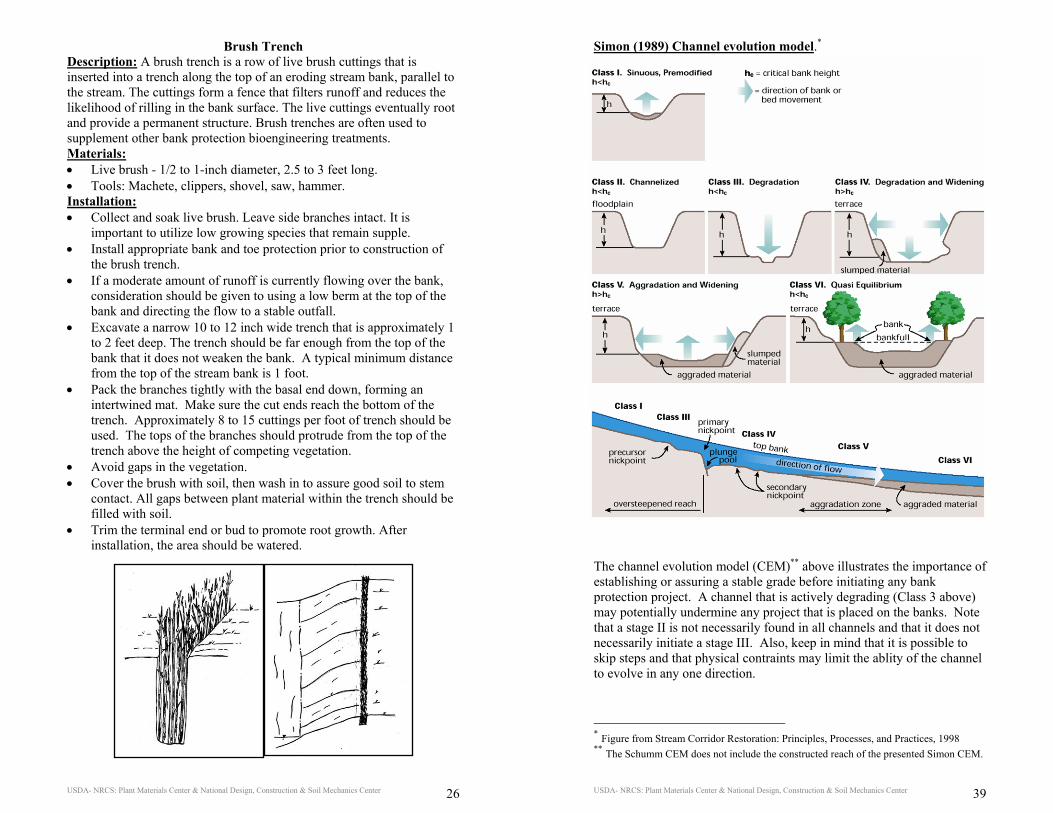
USDA- NRCS: Plant Materials Center & National Design, Construction & Soil Mechanics Center 26
Brush Trench Description: A brush trench is a row of live brush cuttings that is inserted into a trench along the top of an eroding stream bank, parallel to the stream. The cuttings form a fence that filters runoff and reduces the likelihood of rilling in the bank surface. The live cuttings eventually root and provide a permanent structure. Brush trenches are often used to supplement other bank protection bioengineering treatments. Materials: • Live brush - 1/2 to 1-inch diameter, 2.5 to 3 feet long. • Tools: Machete, clippers, shovel, saw, hammer. Installation: • Collect and soak live brush. Leave side branches intact. It is
important to utilize low growing species that remain supple. • Install appropriate bank and toe protection prior to construction of
the brush trench. • If a moderate amount of runoff is currently flowing over the bank,
consideration should be given to using a low berm at the top of the bank and directing the flow to a stable outfall.
• Excavate a narrow 10 to 12 inch wide trench that is approximately 1 to 2 feet deep. The trench should be far enough from the top of the bank that it does not weaken the bank. A typical minimum distance from the top of the stream bank is 1 foot.
• Pack the branches tightly with the basal end down, forming an intertwined mat. Make sure the cut ends reach the bottom of the trench. Approximately 8 to 15 cuttings per foot of trench should be used. The tops of the branches should protrude from the top of the trench above the height of competing vegetation.
• Avoid gaps in the vegetation. • Cover the brush with soil, then wash in to assure good soil to stem
contact. All gaps between plant material within the trench should be filled with soil.
• Trim the terminal end or bud to promote root growth. After installation, the area should be watered.
USDA- NRCS: Plant Materials Center & National Design, Construction & Soil Mechanics Center 39
Simon (1989) Channel evolution model.* The channel evolution model (CEM)** above illustrates the importance of establishing or assuring a stable grade before initiating any bank protection project. A channel that is actively degrading (Class 3 above) may potentially undermine any project that is placed on the banks. Note that a stage II is not necessarily found in all channels and that it does not necessarily initiate a stage III. Also, keep in mind that it is possible to skip steps and that physical contraints may limit the ablity of the channel to evolve in any one direction.
* Figure from Stream Corridor Restoration: Principles, Processes, and Practices, 1998 ** The Schumm CEM does not include the constructed reach of the presented Simon CEM.
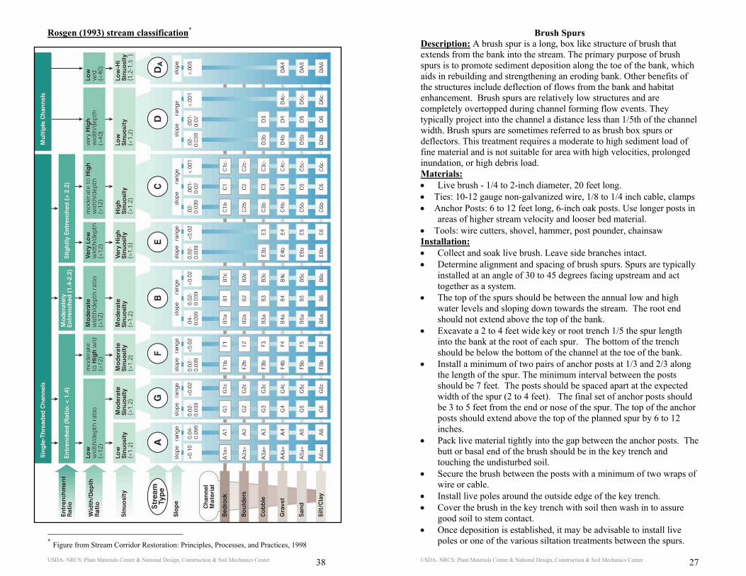
USDA- NRCS: Plant Materials Center & National Design, Construction & Soil Mechanics Center 38
Rosgen (1993) stream classification*
* Figure from Stream Corridor Restoration: Principles, Processes, and Practices, 1998
USDA- NRCS: Plant Materials Center & National Design, Construction & Soil Mechanics Center 27
Brush Spurs Description: A brush spur is a long, box like structure of brush that extends from the bank into the stream. The primary purpose of brush spurs is to promote sediment deposition along the toe of the bank, which aids in rebuilding and strengthening an eroding bank. Other benefits of the structures include deflection of flows from the bank and habitat enhancement. Brush spurs are relatively low structures and are completely overtopped during channel forming flow events. They typically project into the channel a distance less than 1/5th of the channel width. Brush spurs are sometimes referred to as brush box spurs or deflectors. This treatment requires a moderate to high sediment load of fine material and is not suitable for area with high velocities, prolonged inundation, or high debris load. Materials: • Live brush - 1/4 to 2-inch diameter, 20 feet long. • Ties: 10-12 gauge non-galvanized wire, 1/8 to 1/4 inch cable, clamps • Anchor Posts: 6 to 12 feet long, 6-inch oak posts. Use longer posts in
areas of higher stream velocity and looser bed material. • Tools: wire cutters, shovel, hammer, post pounder, chainsaw Installation: • Collect and soak live brush. Leave side branches intact. • Determine alignment and spacing of brush spurs. Spurs are typically
installed at an angle of 30 to 45 degrees facing upstream and act together as a system.
• The top of the spurs should be between the annual low and high water levels and sloping down towards the stream. The root end should not extend above the top of the bank.
• Excavate a 2 to 4 feet wide key or root trench 1/5 the spur length into the bank at the root of each spur. The bottom of the trench should be below the bottom of the channel at the toe of the bank.
• Install a minimum of two pairs of anchor posts at 1/3 and 2/3 along the length of the spur. The minimum interval between the posts should be 7 feet. The posts should be spaced apart at the expected width of the spur (2 to 4 feet). The final set of anchor posts should be 3 to 5 feet from the end or nose of the spur. The top of the anchor posts should extend above the top of the planned spur by 6 to 12 inches.
• Pack live material tightly into the gap between the anchor posts. The butt or basal end of the brush should be in the key trench and touching the undisturbed soil.
• Secure the brush between the posts with a minimum of two wraps of wire or cable.
• Install live poles around the outside edge of the key trench. • Cover the brush in the key trench with soil then wash in to assure
good soil to stem contact. • Once deposition is established, it may be advisable to install live
poles or one of the various siltation treatments between the spurs.
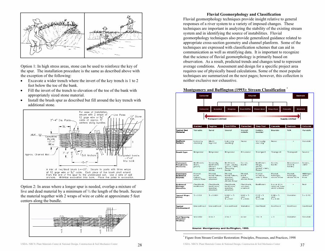
USDA- NRCS: Plant Materials Center & National Design, Construction & Soil Mechanics Center 28
Option 1: In high stress areas, stone can be used to reinforce the key of the spur. The installation procedure is the same as described above with the exception of the following: • Excavate a wider trench where the invert of the key trench is 1 to 2
feet below the toe of the bank. • Fill the invert of the trench to elevation of the toe of the bank with
appropriately sized stone material. • Install the brush spur as described but fill around the key trench with
additional stone.
Option 2: In areas where a longer spur is needed, overlap a mixture of live and dead material by a minimum of ½ the length of the brush. Secure the material together with 2 wraps of wire or cable at approximate 5 feet centers along the bundle.
USDA- NRCS: Plant Materials Center & National Design, Construction & Soil Mechanics Center 37
Fluvial Geomorphology and Classification Fluvial geomorphology techniques provide insight relative to general responses of a river system to a variety of imposed changes. These techniques are important in analyzing the stability of the existing stream system and in identifying the source of instabilities. Fluvial geomorphology techniques also provide generalized guidance related to appropriate cross-section geometry and channel planform. Some of the techniques are expressed with classification schemes that can aid in communication as well as stratifying data. It is important to recognize that the science of fluvial geomorphology is primarily based on observation. As a result, predicted trends and changes tend to represent average conditions. Assessment and design for a specific project area requires use of physically based calculations. Some of the most popular techniques are summarized on the next pages; however, this collection is neither exclusive nor exhaustive. Montgomery and Buffington (1993): Stream Classification *
* Figure from Stream Corridor Restoration: Principles, Processes, and Practices, 1998
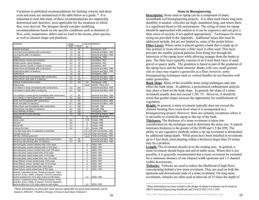
USDA- NRCS: Plant Materials Center & National Design, Construction & Soil Mechanics Center 36
Variations in published recommendations for limiting velocity and shear exist and some are summarized in the table below as a guide. * It is important to note that many of these recommendations are empirically determined and, therefore, most applicable for the situations in which they were derived. The designer should consider modifying recommendations based on site specific conditions such as duration of flow, soils, temperature, debris and ice load in the stream, plant species, as well as channel shape and planform.
Treatment shear Velocity referencelb/ft2 N/m2 fps
Fascine revetment 1.4 69 Schoklitsch, 1937Live Fascine (immediately after construction) 1.2 60 Schiechtl and Stern, 1994Live Fascine (after 3-4 seasons) 1.6 80 Schiechtl and Stern, 1994Fascine 2.1 103 Gerstgraser, 1999
Wattle (woven, coarse sand between) 0.2 10 Schoklitsch, 1937Wattles (woven, gravel between) 0.3 15 Schoklitsch, 1937Wattles (woven, parallel or oblique to current) 1.0 49 Schoklitsch, 1937Wattle fence (immediately after construction) 0.2 10 Schiechtl and Stern, 1994Wattle fence (after 3-4 seasons) 1.0 50 Schiechtl and Stern, 1994Wattle fence 1.0 49 Gerstgraser, 1999
Willow Brush Layer (immediately after construction) 0.4 20 Schiechtl and Stern, 1994Willow Brush Layer (after 3-4 seasons) 2.9 140 Schiechtl and Stern, 1994
Cuttings of willows/willow stakes 2.0 100 9.8 Gerstgraser, 1999Willow posts 5 to 8 USACE TR EL 97-8Live Stakes in riprap (immediately after construction) 4.0 200 Schiechtl and Stern, 1994Live Stakes in riprap (after 3-4 seasons) 6.0 300 Schiechtl and Stern, 1994
Live cuttings in coarse gravel (immediately after construction) 1.0 50 Schiechtl and Stern, 1994Live cuttings in coarse gravel (after 3-4 seasons) 5.0 250 Schiechtl and Stern, 1994
Brush mat (immediately after construction) 1.0 50 Schiechtl and Stern, 1994Brush mat (after 3-4 seasons) 6.1 300 Schiechtl and Stern, 1994Willow Brush mat (immediately after construction) 4.1 200 Florineth, 1982Willow Brush mat (after 3-4 seasons) 8.2 400 Florineth, 1982Brush Mattress w/willows 6.5 320 Gerstgraser, 1999Stone sill with live joint plantings 3.0 150 Schiechtl and Stern, 1994Rootwads 8 USACE TR EL 97-8
Sandy Loam 0.0 1.75 Temple, 1980Silt loam 0.0 2 Temple, 1980Alluvial silts 0.0 2 Temple, 1980Ordinary firm loam 0.0 2.5 Temple, 1980Very light loose sand, no vegetation or protection 1 to 1.5 Fortier and Scobey, 1926Average sandy soil 2 to 2.5 Fortier and Scobey, 1926Stiff clay, ordinary gravel soil 4 to 5 Fortier and Scobey, 1926
Deciduous tree plantings (immediately after construction) 0.4 20 Schiechtl and Stern, 1994Deciduous tree planting (after 3-4 seasons) 2.4 120 Schiechtl and Stern, 1994
Bermuda grass, erosion resistant soils, 0-5% slope 8 USDA, 1947Bermuda grass, erosion resistant soils, 5-10% slope 7 USDA, 1947Bermuda grass, erosion resistant soils, over 10% slope 6 USDA, 1947Bermuda grass, easily eroded soils, 0-5% slope 6 USDA, 1947Bermuda grass, easily eroded soils, 5-10% slope 5 USDA, 1947Bermuda grass, easily eroded soils, over 10% slope 4 USDA, 1947Grass Mixture, erosion resistant soils, 0-5% slope 5 USDA, 1947Grass Mixture, erosion resistant soils, 5-10% slope 4 USDA, 1947Grass mixture, easily eroded soils, 0-5% slope 4 USDA, 1947Grass mixture, easily eroded soils, 5-10% slope 3 USDA, 1947Grasses: Lespedeza sericea, Weeping lovegrass, Yellow bluestem, Kudzu, Alfalfa, Crabgrass, Common lespedeza; erosion resistant soil, 0-5% slope unless on side slopes 3.5 USDA, 1954Grasses: Lespedeza sericea, Weeping lovegrass, Yellow bluestem, Kudzu, Alfalfa, Crabgrass, Common lespedeza; easily erodible soil, 0-5% slope unless on side slopes 2.5 USDA, 1954
*More information on allowable shear stresses applicable for grass lined channels can be found in ARS 667, “Stability Design of Grass-Lined Open Channels”.
USDA- NRCS: Plant Materials Center & National Design, Construction & Soil Mechanics Center 29
Stone in Bioengineering Description: Stone used as riprap can be a component of many streambank soil bioengineering projects. It is often used where long term durablity is needed, velocities are high, inundation long, and where there is a significant threat to life and property. The sizing of stone for riprap should be approached with caution as it can be expensive and can give a false sence of security if not applied appropriately*. Techniques for stone sizing are provided in the Appendix. Additional issues that must be addressed include, but are not limited to, some of the points below: Filter Layer: Where stone is placed against a bank that is made up of fine grained or loose alluvium, a filter layer is often used. This layer prevents the smaller grained particles from being lost through the interstices of the riprap layer while allowing seepage from the banks to pass. The filter layer typically consists of an 8-inch thick layer of sand, gravel or quarry spalls. The gradation is based in part of the gradation of the riprap layer and the bank material. Banks with very small grained silts or clays may require a geotextile as a filter; however, some bioengineering techniques such as vertical bundles do not function well under geotextiles. Bank Slope: Many of the available stone sizing techniques take into effect the bank slope. In addition, a geotechnical embankment analysis may place a limit on the bank slope. In general, the slope of a stone revetment usually does not exceed 1.5H: 1V. However, it should be noted that gentler slopes increase the opportunity for establishment of vegetation. Height: In general, a stone revetment typically does not exceed the channel forming flow event level when it is incorporated in a bioengineering project. However, there are certainly exceptions where it is advisable to extend the riprap to the top of the bank. Thickness: The thickness of a stone revetment is taken into consideration by the technique used to determine the stone size. A typical minimum thickness is the greater of the D100 and 1.5 the D50. The ability to use vegetative methods within a rip rap revetment is diminished by additional riprap depth. While posts have been installed in revetments up to 4 feet thick, joint planting within a thickness larger than 24 inches may be a problem. Length: The revetment should cover the eroding area. In general, a stone revetment should begin and end at stable areas. Where this is not possible, it is generally recommended that a stone revetment be extended for a minimum distance of one channel width upstream and 1.5 channel widths downstream. Tiebacks: Tiebacks are used to reduce the likelihood of high flows concentrating behind a low stone revetment. They are used on both the upstream and downstream ends of a stone revetment. On long stone revetments, tiebacks are often used at intervals of 15 times the depth of
* More information on issues related to the design of riprap revetments can be found in NRCS National Engineering Handbook and USACE EM 1110-2-1601
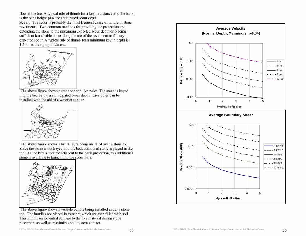
USDA- NRCS: Plant Materials Center & National Design, Construction & Soil Mechanics Center 30
flow at the toe. A typical rule of thumb for a key in distance into the bank is the bank height plus the anticipated scour depth. Scour: Toe scour is probably the most frequent cause of failure in stone revetments. Two common methods for providing toe protection are extending the stone to the maximum expected scour depth or placing sufficient launchable stone along the toe of the revetment to fill any expected scour. A typical rule of thumb for a minimum key in depth is 1.5 times the riprap thickness.
The above figure shows a stone toe and live poles. The stone is keyed into the bed below an anticipated scour depth. Live poles can be installed with the aid of a waterjet stinger. The above figure shows a brush layer being installed over a stone toe. Since the stone is not keyed into the bed, additional stone is placed in the toe. As the bed is scoured adjacent to the bank protection, this additional stone is available to launch into the scour hole.
The above figure shows a verticle bundle being installed under a stone toe. The bundles are placed in trenches which are then filled with soil. This minimizes potential damage to the live material during stone placement as well as maximizes soil to stem contact.
USDA- NRCS: Plant Materials Center & National Design, Construction & Soil Mechanics Center 35
Average Velocity (Normal Depth, Manning's n=0.04)
0.0001
0.001
0.01
0.1
0 1 2 3 4 5
Hydraulic Radius
Fric
tion
Slop
e (ft
/ft)
1 fps
2 fps
3 fps
5 fps
10 fps
Average Boundary Shear
0.0001
0.001
0.01
0.1
0 1 2 3 4 5
Hydraulic Radius
Fric
tion
Slop
e (ft
/ft)
.1 lb/ft^2
.5 lb/ft^2
1 lb/f t^2
2 lb/f t^2
5 lb/f t^2
10 lb/ft^2
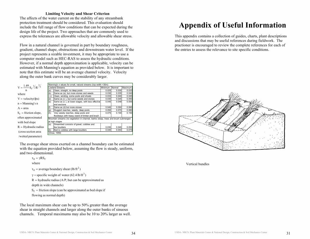
USDA- NRCS: Plant Materials Center & National Design, Construction & Soil Mechanics Center 34
Limiting Velocity and Shear Criterion The affects of the water current on the stability of any streambank protection treatment should be considered. This evaluation should include the full range of flow conditions that can be expected during the design life of the project. Two approaches that are commonly used to express the tolerances are allowable velocity and allowable shear stress. Flow in a natural channel is governed in part by boundary roughness, gradient, channel shape, obstructions and downstream water level. If the project represents a sizable investment, it may be appropriate to use a computer model such as HEC-RAS to assess the hydraulic conditions. However, if a normal depth approximation is applicable, velocity can be estimated with Manning's equation as provided below. It is important to note that this estimate will be an average channel velocity. Velocity along the outer bank curves may be considerably larger. The average shear stress exerted on a channel boundary can be estimated with the equation provided below, assuming the flow is steady, uniform, and two-dimensional.
The local maximum shear can be up to 50% greater than the average shear in straight channels and larger along the outer banks of sinuous channels. Temporal maximums may also be 10 to 20% larger as well.
depth) normal as flowing if slope bed as edapproximat be(can slopefriction S
channels) in widedepth as edapproximat becan but (A/P, radius hydraulicR
)lb/ft (62.4 water of weight specific γ
)(lb/ftshear boundary averageτ
whereγRSτ
f
3
20
f0
=
==
=
=
Manning's n values for small, natural streams (top width <30m)Lowland Streams Minimum Normal Maximum(a) Clean, straight, no deep pools 0.025 0.030 0.033(b) Same as (a), but more stones and weeds 0.030 0.035 0.040( c) Clean, winding, some pools and shoals 0.033 0.040 0.045(d) Same as (c ), but some weeds and stones 0.035 0.045 0.050(e) Same as (c ), at lower stages, with less effective 0.040 0.048 0.055
and sections(f) Same as (d) but more stones 0.045 0.050 0.060(g) Sluggish reaches, weedy, deep pools 0.050 0.070 0.080(h) Very weedy reaches, deep pools and 0.075 0.100 0.150
floodways with heavy stand of timber and brushMountain streams (no vegetation in channel, banks steep, trees and brush submerged at high stages(a) Streambed consists of gravel, cobbles and
few boulders 0.030 0.040 0.050(b) Bed is cobbles with large boulders 0.040 0.050 0.070(Chow, 1959)
parameter) /wetted areasection (cross
radius HydraulicRslope bedwith
edapproximatoften slope,friction S
areaAn sManning' n
ps)velocity(fVwhere
RSn
1.49V
f
32
21
f
=
====
=
USDA- NRCS: Plant Materials Center & National Design, Construction & Soil Mechanics Center 31
Appendix of Useful Information This appendix contains a collection of guides, charts, plant descriptions and discussions that may be useful references during fieldwork. The practioner is encouraged to review the complete references for each of the entries to assess the relevance to site specific conditions.
Vertical bundles
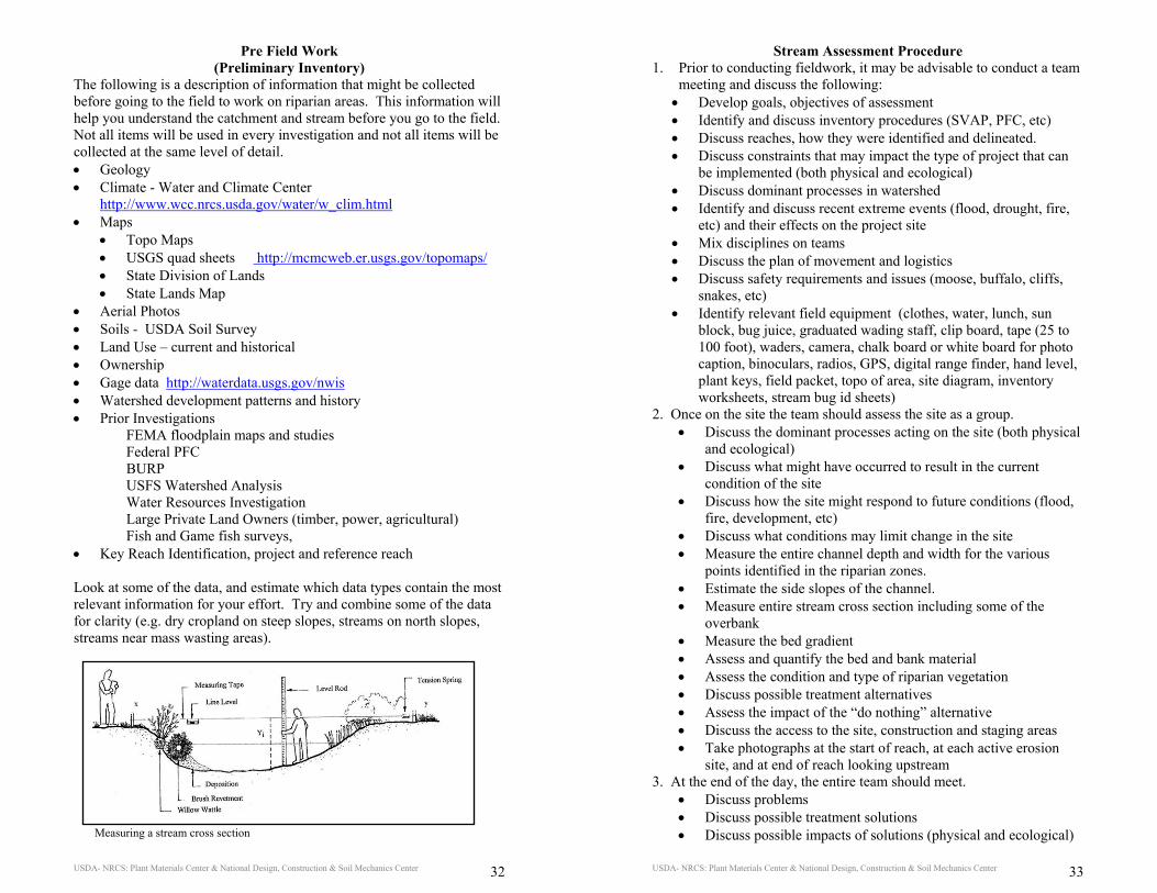
USDA- NRCS: Plant Materials Center & National Design, Construction & Soil Mechanics Center 32
Pre Field Work (Preliminary Inventory)
The following is a description of information that might be collected before going to the field to work on riparian areas. This information will help you understand the catchment and stream before you go to the field. Not all items will be used in every investigation and not all items will be collected at the same level of detail. • Geology • Climate - Water and Climate Center
http://www.wcc.nrcs.usda.gov/water/w_clim.html • Maps
• Topo Maps • USGS quad sheets http://mcmcweb.er.usgs.gov/topomaps/ • State Division of Lands • State Lands Map
• Aerial Photos • Soils - USDA Soil Survey • Land Use – current and historical • Ownership • Gage data http://waterdata.usgs.gov/nwis • Watershed development patterns and history • Prior Investigations FEMA floodplain maps and studies
Federal PFC BURP USFS Watershed Analysis Water Resources Investigation Large Private Land Owners (timber, power, agricultural) Fish and Game fish surveys, • Key Reach Identification, project and reference reach Look at some of the data, and estimate which data types contain the most relevant information for your effort. Try and combine some of the data for clarity (e.g. dry cropland on steep slopes, streams on north slopes, streams near mass wasting areas).
Measuring a stream cross section
USDA- NRCS: Plant Materials Center & National Design, Construction & Soil Mechanics Center 33
Stream Assessment Procedure 1. Prior to conducting fieldwork, it may be advisable to conduct a team
meeting and discuss the following: • Develop goals, objectives of assessment • Identify and discuss inventory procedures (SVAP, PFC, etc) • Discuss reaches, how they were identified and delineated. • Discuss constraints that may impact the type of project that can
be implemented (both physical and ecological) • Discuss dominant processes in watershed • Identify and discuss recent extreme events (flood, drought, fire,
etc) and their effects on the project site • Mix disciplines on teams • Discuss the plan of movement and logistics • Discuss safety requirements and issues (moose, buffalo, cliffs,
snakes, etc) • Identify relevant field equipment (clothes, water, lunch, sun
block, bug juice, graduated wading staff, clip board, tape (25 to 100 foot), waders, camera, chalk board or white board for photo caption, binoculars, radios, GPS, digital range finder, hand level, plant keys, field packet, topo of area, site diagram, inventory worksheets, stream bug id sheets)
2. Once on the site the team should assess the site as a group. • Discuss the dominant processes acting on the site (both physical
and ecological) • Discuss what might have occurred to result in the current
condition of the site • Discuss how the site might respond to future conditions (flood,
fire, development, etc) • Discuss what conditions may limit change in the site • Measure the entire channel depth and width for the various
points identified in the riparian zones. • Estimate the side slopes of the channel. • Measure entire stream cross section including some of the
overbank • Measure the bed gradient • Assess and quantify the bed and bank material • Assess the condition and type of riparian vegetation • Discuss possible treatment alternatives • Assess the impact of the “do nothing” alternative • Discuss the access to the site, construction and staging areas • Take photographs at the start of reach, at each active erosion
site, and at end of reach looking upstream 3. At the end of the day, the entire team should meet.
• Discuss problems • Discuss possible treatment solutions • Discuss possible impacts of solutions (physical and ecological)