Embed Size (px)
Citation preview

Southern Highlands Regional Shooting Complex
Soil and Water Management Plan Construction and Operational Phases
June 2016

Southern Highlands Regional Shooting Complex
Soil and Water Management Plan
Third Party Review June 2016 by: Environmental Strategies Pty Ltd Suite 15 - 201, Locomotive Workshop, 2 Locomotive St, Eveleigh, NSW 2015
Updated June 2016 by:
ErSed Environmental Pty Ltd PO Box 1124 Leichhardt NSW 2040
Updated November 2010 by: GHD Pty Ltd 133 Castlereagh Street Sydney NSW 2000
Issued September 2010 by: GHD Pty Ltd 133 Castlereagh Street Sydney NSW 2000
Southern Highlands Regional Shooting Complex
Soil and Water Management Plan
Contents 1 Introduction ............................................................................................................................ 1
1.1 General Purpose and Objective .................................................................................................... 1
1.2 SWMP Requirements.................................................................................................................... 1
1.3 Mitigation Measures .................................................................................................................... 2
2 SHRSC Description ................................................................................................................... 4
2.1 Site Location and Description ....................................................................................................... 4
2.2 Surrounding Land Uses and Sensitive Receptors ........................................................................... 6
2.3 Geology, Soils and Topography ..................................................................................................... 6
2.4 Hydrogeology ............................................................................................................................... 7
2.5 Hydrology ..................................................................................................................................... 7
2.6 Water Quality ............................................................................................................................... 8
3 Environmental Impact ............................................................................................................. 9
4 Mitigation and Control .......................................................................................................... 10
4.1 Stormwater Management ...........................................................................................................10
4.2 Post Development Runoff ............................................................................................................12
4.3 Wastewater Management System ...............................................................................................12
4.4 Permanent Erosion Control .........................................................................................................12
4.5 Application of Soil Amendments ..................................................................................................12
5 Monitoring Programs ............................................................................................................ 13
5.1 Operational Phase Monitoring .....................................................................................................13
5.2 Construction Monitoring Program ...............................................................................................13
Appendix A ................................................................................................................................... 17
Soil and Water Management Plan Drawings ............................................................................................17

Southern Highlands Regional Shooting Complex
Soil and Water Management Plan
Table Index
Table 1 Minister’s Requirements .............................................................................................................. 1
Table 2 BOM Daily Rainfall Data ................................................................................................................ 7
Table 3 Construction Surface Water Quality Program ..............................................................................14
Table 4 Construction Monitoring Program – Visual Inspections ................................................................15
Figure Index
Figure 1 Site Location ............................................................................................................................. 5
Figure 2 Water Catchment ..................................................................................................................... 8

Southern Highlands Regional Shooting Complex
Soil and Water Management Plan Page 1 of 17
1 Introduction
1.1 General Purpose and Objective The purpose of this Soil and Water Management Plan (SWMP) is to minimise the risk to human health or the environment during the construction and operational phases of the Southern Highlands Regional Shooting Complex (SHRSC, ‘the Site’) by reducing the potential for sediment, metal (and other) contamination to migrate to nearby sensitive receptors. The management plan includes details on:
• Aspects of range design associated with pollution control and minimisation; • Stormwater and wastewater management structures; • Erosion control measures; • The application of soil amendments to reduce the risk of metal mobilisation and
transport; and • The environmental monitoring program.
This plan is prepared in accordance with US EPA (June 2005) Best management practices for lead outdoor shooting ranges, EPA-902-B-01-001 and NSW Landcom’s Soils and Construction: Managing Urban Stormwater (2004) manual.
This plan should be read in conjunction with the Water Cycle Management Plan (WCMP) and Operational Environmental Management Plan (OEMP) also prepared for the SHRSC.
1.2 SWMP Requirements This management plan addresses particular issues contained within the Minister’s Determination for the SHRS, as listed in Table 1.
Table 1 Minister’s Requirements
Requirement Relevant Section
A Soil and Water Management Plan shall be prepared to meet the requirements outlined in Chapter 2 of the NSW Landcom’s Soils and Construction: Managing Urban Stormwater (2004) manual – the “Blue Book”. A copy of the Plan shall be submitted to the Department of Planning All
The design capacity of the amended soil wastewater treatment and disposal system for the proposed shooting complex, including upgrade or transfer of the wastewater system at the existing Hill Top rifle range, must be based on average and peak wastewater loads expected to be generated at the site.
Section 4.2.4 of the Water Cycle
Management Plan
The amended soil mound must be located at least 100 metres from the Rocky Waterholes Creek or any other perennial or intermittent creek or watercourse, and at least 40 metres from any drainage depression and dam.
Section 4.2.4 of the Water Cycle
Management Plan

Southern Highlands Regional Shooting Complex
Soil and Water Management Plan Page 2 of 17
Requirement Relevant Section
A detailed water cycle management plan (WCMP) for the operation of the complex prepared by a person with knowledge and experience in the preparation of such plans which is to incorporate the elements of Appendix E of the Environmental Assessment.
Water Cycle Management Plan
Plans and procedures for the remediation of any contaminated soils on the site.
Section 4.2.5 and 4.2.6 of the Water Cycle Management
Plan and OEMP
Construction monitoring plan, including monitoring of surface water and engineering controls.
Section 5 of this Soil and Water
Management Plan
1.3 Mitigation Measures The following mitigation measures (in general) would be implemented to combat the potential environmental impacts from the proposal to develop the SHRSC:
• The existing 800m range stopbutt at the SHRSC will be remediated in accordance with NSW EPA requirements so that it meets health and ecological investigation levels suitable for recreational open spaces. A Site Audit Statement prepared by a qualified site auditor to assess the existing stopbutt and confirm that it has been remediated and is suitable for its intended use;
• Engineering controls isolate areas routinely contaminated by bullet strike (primary and secondary impact) from the surrounding catchment.
• Future remediation of soils if monitoring indicates exceedance of relevant contamination assessment criteria based on the land use;
• Five (5) sediment control ponds with a combined storage volume of 5,400m3 established at the commencement of construction have been retained for operational use of the SHRSC. Future development of the site will include another sediment control pond with a storage volume of 1,230m3;
• New stopbutts and target mounds are designed to reduce erosion, including the construction of a 3(h):1(v) slope to improve stability, to promote low-velocity sheet flow, and to assist with vegetation establishment. Note the angle of the forward slope is specified by NSW Police range guidelines as being at least 30o but ideally 35o in relation to the range fairway;
• New stopbutts have been constructed from suitable clean site soils or imported clean fill and all rocks and other debris removed to minimise the potential for ricochet;
• New stopbutts are designed to minimise contact between water and projectiles to reduce the rate of projectile deterioration and metal leaching; and

Southern Highlands Regional Shooting Complex
Soil and Water Management Plan Page 3 of 17
• The SHRSC Operation Environmental Management Plan (OEMP) includes the following measures: o The usage of firing lanes at rifle and pistol ranges would be staggered to
minimise effects on stopbutt stability; o Surface Soils within Shot Fall zones (primary and secondary impacts) are
monitored and treated as required to maintain Soil pH within the range of 6.5-8.5 to reduce the leaching and mobility of metals.
o Grass cover is maintained over all areas other than primary impact zones as an erosion control. Vegetation cover also acts to mitigate movement of sediment in run off and migration of contaminants attached to sediments.
o Fertiliser application and soil ameliorants are used where required to promote the maintenance of the protective grass cover. Regular soil testing is used to inform and confirm correct fertiliser application and avoid potential excessive application and offsite impacts.
o Where feasible the use of less toxic projectiles (i.e. non lead) would be promoted by the Office of Sport; and
o An operational monitoring program for the SHRSC is in place to monitor possible metal accumulation and migration in and around the site. The monitoring program is outlined in Section 5 of the Water Cycle Management Plan.

Southern Highlands Regional Shooting Complex
Soil and Water Management Plan Page 4 of 17
2 SHRSC Description The SHRSC is a regional recreational shooting complex incorporating the existing 800 metre Hill Top Rifle Range (which continues to operate), and includes:
• A (500 metres by 100 metres) shooting range; • A (50 metres by 115 metres) shooting range; • Supporting facilities and infrastructure, including:
o Range control and Toilet facilities; o Access roads (designed for two-wheel drive vehicle access) connecting to
Wattle Ridge Road and between the ranges; o Diesel generator, solar panels, water supply tanks and septic system; o Informal parking for 160 cars; and o Ponds to contain water for water quality control purposes.
• Future facilities include: o A (200 metres by 85 metres) shooting range; o A shotgun range; o An indoor air range (21 metres by 17 metres by 6.5 metres); and o A Clubhouse
2.1 Site Location and Description The SHRSC is located in the Wingecarribee LGA on Wattle Ridge Road, approximately 5.5 km northwest of the centre of the village of Hill Top in the southern highlands of New South Wales, approximately 11 km north of Mittagong. Mittagong is located at the south-western end of the Sydney Basin between the upper reaches of the Nepean River and other rivers such as the Wollondilly, Nattai, Bargo and Wingecarribee. These rivers flow into the Nepean River further to the north. See Figure 1 – Site Location.
The Wingecarribee Local Environmental Plan 1989 (the LEP) applies to the site.
The site is currently the location of the Hill Top Rifle Range. The Southern Highlands Rifle Club licensed land on which the range is located, from the National Parks and Wildlife Service, on 3 June 1993. The existing Hilltop Rifle Range consists of a seven-target rifle range 800 m long, with firing mounds at 100 m intervals. A small clubhouse, toilet facilities and informal car parking are also located on site.
1,036 hectares (ha) of land has been excised from the Bargo State Conservation Area by means of the National Parks and Wildlife (Adjustment of Areas) Act 2006. The SHRSC occupies an area of approximately 16 ha within this land. The area occupied by the range and associated facilities was cleared as per the Conditions of Approval. The remainder of the land on the site (approximately 1,000 ha) has been retained in its existing condition as a vegetation buffer zone. This area acts as a safety zone for the SHRSC.

Southern Highlands Regional Shooting Complex
Soil and Water Management Plan Page 5 of 17
Figure 1 Site Location

Southern Highlands Regional Shooting Complex
Soil and Water Management Plan Page 6 of 17
2.2 Surrounding Land Uses and Sensitive Receptors The site is bounded by:
• Wattle Ridge – a grazing property/residence which adjoins the site to the northwest (located approximately 2.5 km north of the existing range);
• Bargo State Conservation Area to the southwest; • A 330 kV cleared electricity easement (Transgrid) to the southeast; and • Wattle Ridge Road to the northeast.
Bargo State Conservation Area is located further southwest, southeast and northeast. Nattai National Park is located further to the northwest, on the opposite site of the Wattle Ridge property. Nattai National Park is accessible from the end of Wattle Ridge Road approximately 3 km away.
Sensitive receptors include Rocky Waterholes Creek, located approximately 1.5 km south of the site. The creek is a tributary of the Nattai River. The Nattai River is located approximately 7.5 km west of the site.
2.3 Geology, Soils and Topography Topographically and geologically the area is transitional between the Cumberland Plain of the Sydney Basin, and the southern uplands.
The underlying geology of the site comprises the Hawkesbury Sandstone of the Mittagong Formation (Herbert and Helby, 1980). The site lies within an outcrop of the Narrabeen group, which comprises sandstone, claystone and siltstone. The Hawkesbury sandstone overlies a Triassic shale unit, the Wianamatta Group.
The site is characterised by relatively flat topography, being situated on a spurline that trends to the north from the Wattle Ridge Range. This spurline occupies a position between two tributaries of the Rocky Waterholes Creek. All watercourses are upper tributaries of the Nattai River.
The three main groups of soils that occur within the region are (NPWS, 2001):
• Sandstone tableland soils; • Valley soils (sandstone derived); and • Soils associated with nutrient rich shales and igneous rocks.
Land surfaces in the site do not appear to have been significantly transformed. These soil landscape types are unstable when disturbed. They are highly susceptible to mass movement, such as slides and rock falls, as well as wind and water erosion (Hazelton and Tille, 1990). A major cause of erosion in an area of this type is fire. After a fire in which the crowns are consumed, the loose sandy soils remain bare for a long period. If rain then shortly follows a fire, there is a resulting increase in surface run-off, causing increased erosion, and a reduction in plant propagation and animal habitats.
Southern Highlands Regional Shooting Complex
Soil and Water Management Plan Page 7 of 17
2.4 Hydrogeology The site is located within the Hawkesbury Sandstone – southeast groundwater flow system, which consists of a layered aquifer system with yields ranging from less than one to 50 ML/day. Basalt caps are expected to occur in some areas of the Mittagong Ranges, with groundwater from this horizon discharging into seeps, springs and rivers (Sydney Catchment Authority, 2006).
According to the Department of Natural Resources Groundwater Licence database, groundwater within the Hilltop area was found to be present at depths of approximately 20 metres in the sandstone aquifer. The depths to groundwater within the aquifers are expected to be dependent on rainfall and therefore are likely to vary seasonally. A borehole on site near the proposed clubhouse was terminated at 50 m depth with no water detection.
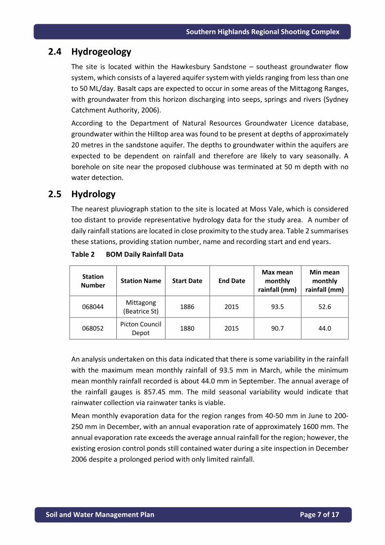
2.5 Hydrology The nearest pluviograph station to the site is located at Moss Vale, which is considered too distant to provide representative hydrology data for the study area. A number of daily rainfall stations are located in close proximity to the study area. Table 2 summarises these stations, providing station number, name and recording start and end years.
Table 2 BOM Daily Rainfall Data
Station Number Station Name Start Date End Date
Max mean monthly
rainfall (mm)
Min mean monthly
rainfall (mm)
068044 Mittagong (Beatrice St) 1886 2015 93.5 52.6
068052 Picton Council Depot 1880 2015 90.7 44.0
An analysis undertaken on this data indicated that there is some variability in the rainfall with the maximum mean monthly rainfall of 93.5 mm in March, while the minimum mean monthly rainfall recorded is about 44.0 mm in September. The annual average of the rainfall gauges is 857.45 mm. The mild seasonal variability would indicate that rainwater collection via rainwater tanks is viable.
Mean monthly evaporation data for the region ranges from 40-50 mm in June to 200-250 mm in December, with an annual evaporation rate of approximately 1600 mm. The annual evaporation rate exceeds the average annual rainfall for the region; however, the existing erosion control ponds still contained water during a site inspection in December 2006 despite a prolonged period with only limited rainfall.

Southern Highlands Regional Shooting Complex
Soil and Water Management Plan Page 8 of 17
2.5.1 Waterways Rocky Waterholes Creek, which is immediately south of the SHRSC drains directly to the Nattai River approximately 6 km to the west of the existing Hilltop Rifle Range. The Nattai River drains north to Lake Burragorang. The catchment of Rocky Waterholes Creek is approximately 23.5 square kilometres, while the catchment of the Nattai River upstream of the junction with Rocky Waterholes Creek is some 240 square kilometres. The total catchment area of the Nattai River upstream of Lake Burragorang is 480 square kilometres. Figure 2 below illustrates the major regional catchments within the vicinity of the site.
2.5.2 Onsite Creeks As the site sits on the top of a spurline that runs from north to south, the natural fall is from the centre of the spurline to the east and to the west into steep gullies. The gullies drop from the level of Rocky Waterholes Creek Road down to Rocky Waterholes Creek, a fall of approximately 100 metres over a distance of less than 1 km. As a result of the topography, the site is not subjected to flooding.
Figure 2 Water Catchment
2.6 Water Quality The Hawkesbury Nepean Catchment Management Authority has classified 98% of the Nattai River as being ‘Near Intact’. The Draft Hawkesbury Nepean Catchment Action Plan (2007) identifies a strategy for managing the entire catchment and sets out procedures for looking after the near intact systems such as the Nattai River.

Southern Highlands Regional Shooting Complex
Soil and Water Management Plan Page 9 of 17
3 Environmental Impact Potential environmental impacts resulting from the construction and operational phases of the project are likely to be associated with soil and erosion of the site. These impacts will be addressed by following the requirements within NSW Landcom’s Soils and Construction: Managing Urban Stormwater (2004) manual – the “Blue Book”, through the Mitigation and Control strategies detailed in Section 4 of this plan.

Southern Highlands Regional Shooting Complex
Soil and Water Management Plan Page 10 of 17
4 Mitigation and Control
4.1 Stormwater Management In the context of Water Sensitive Urban Design (WSUD), the planning and design sets out to minimise the hydrological impacts of development on the surrounding environment. The management of stormwater encompasses:
• Water quality management; • Flood management; • Flow management; and • Flow attenuation.
Key planning and design objectives are:
• Protect and enhance natural water systems following development; • Integrate stormwater treatment into the landscape by incorporating
multiple-use corridors, that maximise the visual and recreational amenity of the development;
• Protect water quality draining from development areas; • Reduce runoff and peak flows from developments by employing local
detention measures, minimising impervious areas and maximising re-use (for example through rain water tanks).
Stormwater management for the SHRSC is designed to prevent an increase in the amount of stormwater leaving the site, maintaining the water balance, and to slow the transmission of stormwater to receiving waters to match the existing predevelopment conditions.
Additionally, the stormwater management system prevents the transportation of gross and sediment-born pollutants as much as possible.
Specific strategies include:
• Provision of storm water infrastructure in a ‘treatment train’ approach which provides controls which successively reduces erosion and sediment transport, mitigates leaching and transport of contaminants and final basins to manage water quality.
• Promotion of sheet flow of runoff water over the range surface. Sheet flow lowers the water velocity, which will lower the water’s sediment load–carrying capacity. It avoids potential point source discharge issues and monitoring requirements that may occur with channeled flow. Promoting sheet flow is accomplished by regrading and flattening out the slope of the land surfaces and by creating broad, very shallow drainage pathways to replace ditches or deep, narrow channels;
• Prevention of storm water from impacting on berms or other engineering elements.

Southern Highlands Regional Shooting Complex
Soil and Water Management Plan Page 11 of 17
• Construction of sedimentation/water quality ponds which serve as a final containment measure for water leaving the ranges. The ponds are designed and sized properly to effectively slow the water and allow the suspended solids to settle out.
• The drainage area that the pond will serve is well defined, and the calculated volume of water the pond must handle is accurate; otherwise, the pond’s effectiveness will be minimal. It is proposed that when complete the SHRSC will have six ponds, three located at the 500 m / future 200 m range, one each at the future shotgun and 50 m pistol range and one at the future clubhouse. The ponds have been sized in accordance with the requirements of Landcom Soils and Construction Volume 1 (Landcom; 2004). The sizes of the ponds are as follows:
o Pond 1 at future 200 m range – 2,000 m3; o Pond 2 at 500 m range – 660 m3; o Pond 3 at 500 m range – 1,380 m3; o Pond 4 at 50 m range – 270 m3; o Pond 5 at future Shotgun range – 1,090 m3; and o Pond 6 at the future carpark and clubhouse (existing pond to be
retained to act as erosion control pond during construction) – 1,230 m3;
The capacity of the ponds to contain all runoff expected has been designed based on the 5-day 85th percentile storm depth and for type D/F soils.
The ponds will be utilised for the life of the SHRSC and the water quality monitored as set out in Section 5 – Monitoring Programs.
Dewatering of ponds can occur following sampling to confirm the water complies with the limits set in Table 3 by a National Association of Testing Authorities (NATA) Accredited Laboratory. The waters then may be discharged at the spillway or used for irrigation of range areas.
• Stopbutts and target mounds are designed to reduce erosion, including the construction of a 3(h):1(v) slope to improve stability, to promote low-velocity sheet flow, and to assist with vegetation establishment.
• In an effort to minimise impact to stopbutt stability usage of range firing lanes are staggered.
• Grass is maintained over the ranges and stopbutts for erosion control. • Stopbutt maintenance between lead recovery and recycling operations
involves: o Replacement of eroded areas, reseeding bare areas, maintaining
vegetation. o Placement of temporary erosion controls measures as required to
promote stabilization.

Southern Highlands Regional Shooting Complex
Soil and Water Management Plan Page 12 of 17
• The stopbutt is routinely inspected and filling undertaken to repair areas of concentrated impact points.
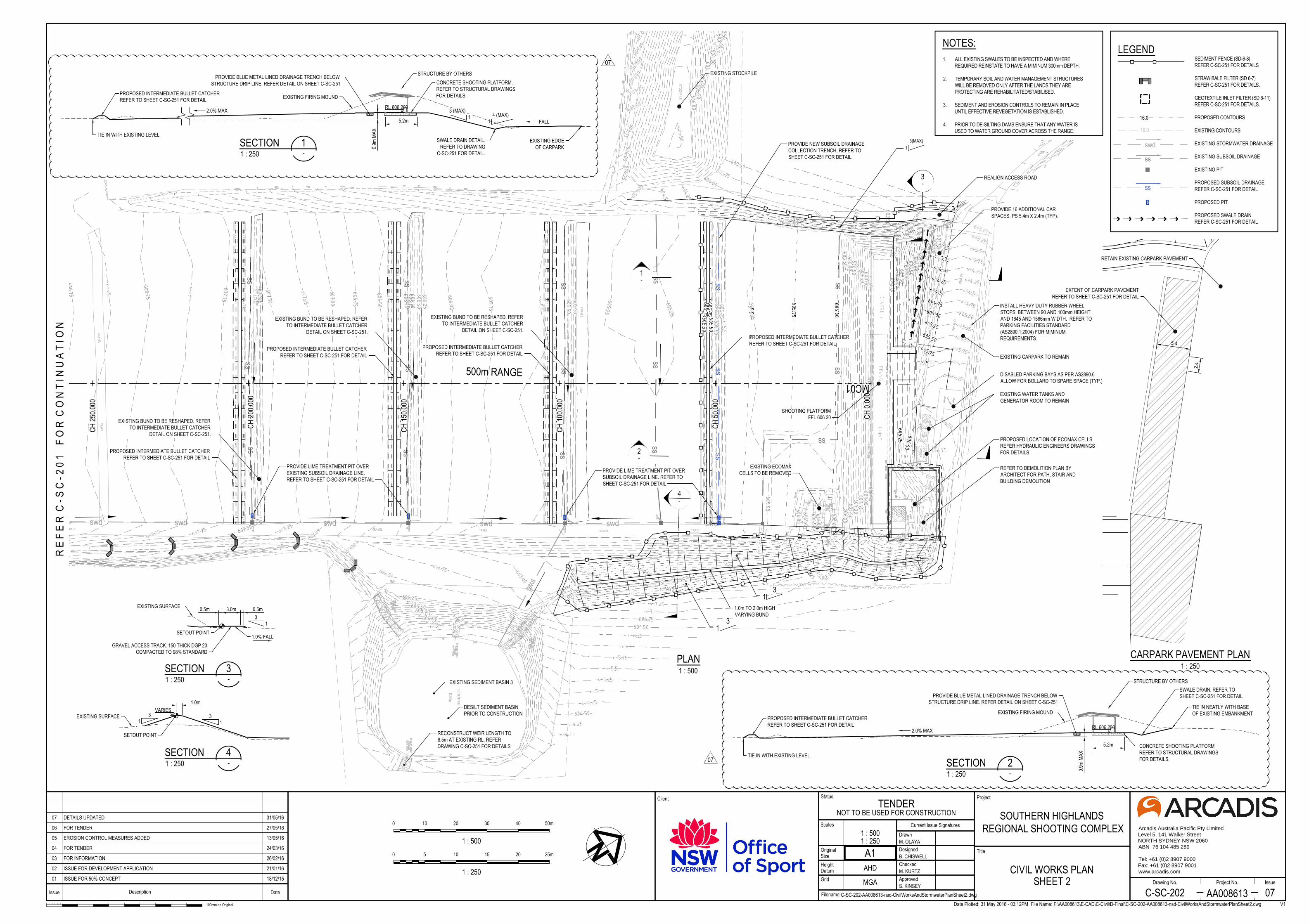
Sediment ponds and the inlet/outlet structures are shown in Appendix A.
4.2 Post Development Runoff Sedimentation ponds will remain following the construction phase. Refer WCMP.
4.3 Wastewater Management System Portable toilets will be brought to site for the duration of the construction period. Sewerage wastes will be removed from the portable toilets as required and the toilets will be removed from site at the end of construction.
As part of the construction works, a packaged wastewater treatment system will be constructed at both the 50m and 500m ranges. The amended soil mound must be located at least 100 metres from the Rocky Waterholes Creek or any other perennial or intermittent creek or watercourse, and at least 40 metres from any drainage depression and dam.
4.4 Permanent Erosion Control Stopbutts and target mounds are designed to reduce erosion, including the construction of a 3(h):1(v) slope to improve stability, to promote low-velocity sheet flow, and to assist with vegetation establishment.
In an effort to minimise impact to stopbutt stability usage of range firing lanes are staggered.
Grass is maintained over the ranges and stopbutts for erosion control.
Construction stage sediment ponds have been left in place.
Diversion and sediment control drains are shown in Appendix A.
4.5 Application of Soil Amendments Based on preliminary assessment, the risk of groundwater contamination from site use is considered likely to be minimal given the considerable depth to groundwater on the site, the shallow depth at which natural bedrock is encountered and the general elevation and topography of the site.
Migration of surface contamination may occur through dissolution of heavy metals via rainfall and transport through surface water runoff. To mitigate contaminant migration, fine agricultural grade lime would be applied to soils within the range, shot fall zones, stopbutts and collection trenches to reduce the mobility of metals by increasing soil pH to within the range of 6.5 to 8.5. The dose of lime required would be determined by laboratory testing and specifications provided for individual lime products.
Re-application of lime would be undertaken when the pH of soils is found to drop below pH 6.5.

Southern Highlands Regional Shooting Complex
Soil and Water Management Plan Page 13 of 17
5 Monitoring Programs
5.1 Operational Phase Monitoring Details of the Operational Phase Monitoring Program have been detailed in the Water Cycle Management Plan. The monitoring program has been initiated at the site to:
Monitor possible metal accumulation and migration from the site during operation. Monitoring includes:
• Soil monitoring; • Sediment monitoring; • Surface water monitoring;
Monitor the function of engineered structures as well as other factors relevant to erosion risk. Monitoring includes:
• Inspection of stop butts, shot fall zones and erosion control structures; and • Inspection of vegetation health and density.
Note: Preliminary sampling exercises have confirmed that routine sampling of Rocky Waterholes Creek is too remote from the facility to readily identify contamination issues or allow practical management response. Rocky Waterholes Creek and other nominated off site sample locations are unable to be routinely accessed in a practicable and safe manner.
5.2 Construction Monitoring Program A construction monitoring program will be implemented at the site to monitor the implemented controls. The monitoring program includes:
• Surface water monitoring; and • Inspection of engineering controls.
Descriptions and requirements for the monitoring program are summarised in Tables 3 and 4. The results of the monitoring are to be incorporated into an annual report to be prepared by Office of Sport and submitted to Water New South Wales.
The report will highlight any failed tests or issues that may have arisen during monitoring and will identify remedial actions or modified management practices to prevent recurrence of any failures.
5.2.1 Assessment Criteria Adopted The criteria used to assess levels of contamination within surface water retained by sediment basins include:
• ANZECC PFWS Protection of fresh water species - 95% trigger value (Australian and New Zealand Guidelines for Fresh and Marine Water Quality, Australian and New Zealand Environment and Conservation Council, 2000) (note the ANZECC PFWS guidelines adopt the NEPM GILs for Freshwater)

Southern Highlands Regional Shooting Complex
Soil and Water Management Plan Page 14 of 17
• ANZECC RWCG Recreational Water Quality Guidelines (Australian and New Zealand Guidelines for Fresh and Marine Water Quality, Australian and New Zealand Environment and Conservation Council, 2000)
• NEPM National Environment Protection (Assessment of Site Contamination) Measure (1999 Amended 2013) Ground Water Investigation Levels (GILs) for Freshwater. Note: As GILs for Antimony (Sb) are not available due to insufficient data, a Low Reliability Trigger Value is adopted from Australian and New Zealand Guidelines for Fresh and Marine Water Quality, Volume 2. Aquatic Ecosystems — Rationale and Background Information (Chapter 8) 2000.
Table 3 Construction Surface Water Quality Program
Construction Surface Water Quality Program
Analytes/Suite Criteria Locations Number of Samples
Frequency
pH
Turbidity /SS
pH 6.0-8.0
50mg/L
Or confirmed by Nephelometric Turbidity Units following laboratory Correlation
Car park (Basin 4) 1 Prior to Dewatering of Basin.
50m (Basin 5) 1
500m East (Basin 3)
500m West (Basin 2)
1
1
200m (Basin 1) 1
Creek waters off range (if available)
2
Notes
1. The pH of creek waters below the site have been shown to have pH just below 6.0 (5.8 & 5.9)
2. During the construction activities at the SHRSC the basins are to be used as sediment control structures. As such appropriate capacity is to be retained within the structure to accommodate runoff from the works areas during a nominated rain fall event.
Unless otherwise accepted by the Office of Sport the following rainfall data should be used in calculation of basin design capacity for erosion and sediment control;
• 5 day 85th percentile rain fall depth = 36.2mm (value for Mittagong from Managing Urban Stormwater Vol 1, 2004)
• Rainfall Erosivity Factor (R)=2500

Southern Highlands Regional Shooting Complex
Soil and Water Management Plan Page 15 of 17
Table 4 Construction Monitoring Program – Visual Inspections
Visual Inspections
Where Search for When
Water Quality Pond Outlets, inlets
and Surrounds
Evidence of scour/ failure of
structure Six monthly and after any severe storm events
Engineering controls including
berms, drains, channels, stopbutts, access tracks and culverts
Evidence of damage, erosion,
sediment outside controlled areas. Six Monthly and after any severe storm events
Range perimeter Evidence of loss and/or damage from stray projectiles
Annually

Southern Highlands Regional Shooting Complex
Soil and Water Management Plan Page 16 of 17
This page has been left blank to aid printing

Southern Highlands Regional Shooting Complex
Soil and Water Management Plan Page 17 of 17
Appendix A
Soil and Water Management Plan Drawings

SHEE
T 2
SHEE
T 1
SHEET 3
50m RANGE
STOP BUTT
EXISTING STOCKPILE
EXISTING SEDIMENT BASIN 5
EXISTING SEDIMENT BASIN 1
EXISTING SEDIMENT BASIN 2
EXISTING STOCKPILE
EXISTING SEDIMENT BASIN 3
STOP BUTT
EXISTING ACCESS TRACK
500m RANGE
SHOOTING PLATFORM
SHOOTING PLATFORM
INSERT A
Issue Description Date
100mm on Original
Project
Title
Client
Project No. IssueDrawing No.
Filename:
Status
Grid
OriginalSize
Scales
Checked
Designed
Drawn
Height
Current Issue Signatures
A1Datum
Approved
AA008613
SOUTHERN HIGHLANDSREGIONAL SHOOTING COMPLEX
Arcadis Australia Pacific Pty Limited
Level 5, 141 Walker Street
NORTH SYDNEY NSW 2060
ABN 76 104 485 289
Tel: +61 (0)2 8907 9000
Fax: +61 (0)2 8907 9001
www.arcadis.com
Date Plotted: 31 May 2016 - 03:11PM File Name: F:\AA008613\E-CAD\C-Civil\D-Final\C-SC-003-AA008613-nsd-GeneralArrangementPlan.dwgC-SC-003-AA008613-nsd-GeneralArrangementPlan.dwg C-SC-003 05
GENERAL ARRANGEMENTPLAN
TENDERNOT TO BE USED FOR CONSTRUCTION
M. OLAYA
B. CHISWELL
M. KURTZ
S. KINSEY
1 : 1500
AHD
MGA01 ISSUE FOR 50% CONCEPT 18/12/15
02 ISSUE FOR DEVELOPMENT APPLICATION 21/01/16
03 FOR INFORMATION 26/02/16
04 FOR TENDER 24/03/16
05 FOR TENDER 27/05/16 0
1 : 1500
30 60 90 120 150m

1-
CH 54
0.000
CH 25
0.000
CH 30
0.000
CH 40
0.000
CH 35
0.000
CH 50
0.000
CH 45
0.000
MC01
RESHAPE 500m RANGE STOP BUTT.REFER DETAIL ON SHEET C-SC-252
OFFSET CURRENT BASE OF STOP BUTTLOCATION TO ACHIEVE EARTHWORKS BALANCEAS PER SHEET C-SC-101
EXISTING SEDIMENT BASIN 2
EXISTING BUND TO BE RESHAPED. REFERTO INTERMEDIATE BULLET CATCHER
DETAIL ON SHEET C-SC-251.
PROPOSED INTERMEDIATE BULLET CATCHERREFER TO SHEET C-SC-251 FOR DETAIL
PROPOSED INTERMEDIATE BULLET CATCHERREFER TO SHEET C-SC-251 FOR DETAIL
500m RANGEEXISTING BUND TO BE RESHAPED. REFER
TO INTERMEDIATE BULLET CATCHERDETAIL ON SHEET C-SC-251.
EXISTING BUND TO BE RESHAPED. REFERTO INTERMEDIATE BULLET CATCHERDETAIL ON SHEET C-SC-251.
PROVIDE LIME TREATMENT PIT OVEREXISTING SUBSOIL DRAINAGE LINE.
REFER TO SHEET C-SC-252 FOR DETAIL.
PROVIDE LIME TREATMENT PIT OVEREXISTING SUBSOIL DRAINAGE LINE.REFER TO SHEET C-SC-252 FOR DETAIL.
swd swd swd
swd
swd
swd
swd swd
ssss
ss
ssss
ss
ssss
ss
CONSTRUCT BUND 200mm HIGH
DESILT SEDIMENT BASINPRIOR TO CONSTRUCTION
CLEAN OUT PIT AND PIPE PRIORTO PLACING STRAWBALE FILTER.
2
SECTION1 : 250
1-
5.0m
3.6m
CURRENT BASE OFSTOP BUTT LOCATION
EXISTING STOP BUTT
RL 619.0031
4.3m
MIN
1.41
1.0% FALL
SETOUT POINT
ss
LEGEND
16.0
16.0
swd
ss
EXISTING STORMWATER DRAINAGE
EXISTING SUBSOIL DRAINAGE
EXISTING PIT
PROPOSED SUBSOIL DRAINAGEREFER C-SC-251 FOR DETAIL
PROPOSED PIT
PROPOSED SWALE DRAINREFER C-SC-251 FOR DETAIL
NOTES:
ss
LEGEND
16.0
16.0
swd
ss
EXISTING STORMWATER DRAINAGE
EXISTING SUBSOIL DRAINAGE
EXISTING PIT
PROPOSED SUBSOIL DRAINAGEREFER C-SC-251 FOR DETAIL
PROPOSED PIT
PROPOSED SWALE DRAINREFER C-SC-251 FOR DETAIL
NOTES:
SECTION1 : 250
2-
41 3
11.4
1
EXISTING SUBSOIL
1.0m
14
R E
F E
R C
- S
C - 2
0 2
F O
R C
O N
T I N
U A
T I O
N
0
1 : 250
5 10 15 20 25m
0
1 : 500
10 20 30 40 50m
PLAN1 : 500
Issue Description Date
100mm on Original
Project
Title
Client
Project No. IssueDrawing No.
Filename:
Status
Grid
OriginalSize
Scales
Checked
Designed
Drawn
Height
Current Issue Signatures
A1Datum
Approved
AA008613
SOUTHERN HIGHLANDSREGIONAL SHOOTING COMPLEX
Arcadis Australia Pacific Pty Limited
Level 5, 141 Walker Street
NORTH SYDNEY NSW 2060
ABN 76 104 485 289
Tel: +61 (0)2 8907 9000
Fax: +61 (0)2 8907 9001
www.arcadis.com
TARGET RAIL SEEDETAIL ON SHEETC-SC-251
TARGET ON RAIL SEEDETAIL ON SHEETC-SC-251
Date Plotted: 31 May 2016 - 03:12PM File Name: F:\AA008613\E-CAD\C-Civil\D-Final\C-SC-201-AA008613-nsd-CivilWorksAndStormwaterPlanSheet1.dwgC-SC-201-AA008613-nsd-CivilWorksAndStormwaterPlanSheet1.dwg C-SC-201 08
V1
CIVIL WORKS PLANSHEET 1
TENDERNOT TO BE USED FOR CONSTRUCTION
M. OLAYA
B. CHISWELL
M. KURTZ
S. KINSEY
1 : 5001 : 250
AHD
MGA01 ISSUE FOR 50% CONCEPT 18/12/15
02 ISSUE FOR DEVELOPMENT APPLICATION 21/01/16
03 FOR INFORMATION 26/02/16
04 FOR TENDER 24/03/16
05 EROSION CONTROL MEASURES ADDED 13/05/16
06 EROSION CONTROL NOTE ADDED 16/05/16
07 FOR TENDER 27/05/16
08 DETAILS UPDATED 31/05/16
07
1-
swd swd swd swd swd swd
swd
ssss
ss
ss
ssss
ss
ssss
ss
ssss
ss
ssss
ss
4-
CH 0.
000
CH 10
0.000
CH 50
.000
CH 20
0.000
CH 15
0.000
CH 25
0.000
MC01
1.0m TO 2.0m HIGHVARYING BUND
EXISTING STOCKPILE
EXISTING BUND TO BE RESHAPED. REFERTO INTERMEDIATE BULLET CATCHER
DETAIL ON SHEET C-SC-251.
PROPOSED INTERMEDIATE BULLET CATCHERREFER TO SHEET C-SC-251 FOR DETAIL
EXISTING BUND TO BE RESHAPED. REFERTO INTERMEDIATE BULLET CATCHER
DETAIL ON SHEET C-SC-251.
PROPOSED INTERMEDIATE BULLET CATCHERREFER TO SHEET C-SC-251 FOR DETAIL
EXISTING BUND TO BE RESHAPED. REFERTO INTERMEDIATE BULLET CATCHER
DETAIL ON SHEET C-SC-251.
PLAN1 : 500
PROPOSED INTERMEDIATE BULLET CATCHERREFER TO SHEET C-SC-251 FOR DETAIL
PROPOSED INTERMEDIATE BULLET CATCHERREFER TO SHEET C-SC-251 FOR DETAIL
SHOOTING PLATFORMFFL 606.20
EXISTING CARPARK TO REMAIN
REALIGN ACCESS ROAD
EXISTING ECOMAXCELLS TO BE REMOVED
500m RANGE
PROVIDE 16 ADDITIONAL CARSPACES. PS 5.4m X 2.4m (TYP).
PROVIDE NEW SUBSOIL DRAINAGECOLLECTION TRENCH, REFER TOSHEET C-SC-251 FOR DETAIL.
INSTALL HEAVY DUTY RUBBER WHEELSTOPS. BETWEEN 90 AND 100mm HEIGHTAND 1645 AND 1566mm WIDTH. REFER TOPARKING FACILITIES STANDARD(AS2890.1:2004) FOR MIMINUMREQUIREMENTS.
PROPOSED LOCATION OF ECOMAX CELLSREFER HYDRAULIC ENGINEERS DRAWINGSFOR DETAILS
DISABLED PARKING BAYS AS PER AS2890.6ALLOW FOR BOLLARD TO SPARE SPACE (TYP.)
REFER TO DEMOLITION PLAN BYARCHITECT FOR PATH, STAIR ANDBUILDING DEMOLITION
3(MAX)1
EXISTING WATER TANKS ANDGENERATOR ROOM TO REMAIN
2-
3-
SECTION1 : 250
2-
EXISTING FIRING MOUND
TIE IN WITH EXISTING LEVEL
2.0% MAX
5.2m CONCRETE SHOOTING PLATFORMREFER TO STRUCTURAL DRAWINGSFOR DETAILS.
0.9m
MAX
PROPOSED INTERMEDIATE BULLET CATCHERREFER TO SHEET C-SC-251 FOR DETAIL
TIE IN NEATLY WITH BASEOF EXISTING EMBANKMENT
STRUCTURE BY OTHERS
PROVIDE BLUE METAL LINED DRAINAGE TRENCH BELOWSTRUCTURE DRIP LINE. REFER DETAIL ON SHEET C-SC-251
SWALE DRAIN. REFER TOSHEET C-SC-251 FOR DETAIL
RL 606.200
SECTION1 : 250
1-
EXISTING EDGEOF CARPARK
EXISTING FIRING MOUND
TIE IN WITH EXISTING LEVEL
2.0% MAX
5.2m
CONCRETE SHOOTING PLATFORM.REFER TO STRUCTURAL DRAWINGSFOR DETAILS.
0.9m
MAX
FALL
SWALE DRAIN DETAIL.REFER TO DRAWING
C-SC-251 FOR DETAIL.
3 (MAX)1
PROPOSED INTERMEDIATE BULLET CATCHERREFER TO SHEET C-SC-251 FOR DETAIL
PROVIDE BLUE METAL LINED DRAINAGE TRENCH BELOWSTRUCTURE DRIP LINE. REFER DETAIL ON SHEET C-SC-251
STRUCTURE BY OTHERS
4 (MAX)1
RL 606.200
SECTION1 : 250
4-
31
31
1.0mVARIES
EXISTING SURFACE
SETOUT POINT
ss
LEGEND
16.0
16.0
swd
ss
EXISTING STORMWATER DRAINAGE
EXISTING SUBSOIL DRAINAGE
EXISTING PIT
PROPOSED SUBSOIL DRAINAGEREFER C-SC-251 FOR DETAIL
PROPOSED PIT
PROPOSED SWALE DRAINREFER C-SC-251 FOR DETAIL
SECTION1 : 250
3-
3.0m3
1
0.5m0.5mEXISTING SURFACE
GRAVEL ACCESS TRACK. 150 THICK DGP 20COMPACTED TO 98% STANDARD
SETOUT POINT1.0% FALL
5.4
2.4
NOTES:
Issue Description Date
100mm on Original
Project
Title
Client
Project No. IssueDrawing No.
Filename:
Status
Grid
OriginalSize
Scales
Checked
Designed
Drawn
Height
Current Issue Signatures
A1Datum
Approved
AA008613
SOUTHERN HIGHLANDSREGIONAL SHOOTING COMPLEX
Arcadis Australia Pacific Pty Limited
Level 5, 141 Walker Street
NORTH SYDNEY NSW 2060
ABN 76 104 485 289
Tel: +61 (0)2 8907 9000
Fax: +61 (0)2 8907 9001
www.arcadis.com
R E
F E
R C
- S
C - 2
0 1
F O
R C
O N
T I N
U A
T I O
N
0
1 : 250
5 10 15 20 25m
0
1 : 500
10 20 30 40 50m
EXTENT OF CARPARK PAVEMENTREFER TO SHEET C-SC-251 FOR DETAIL
CARPARK PAVEMENT PLAN1 : 250
Date Plotted: 31 May 2016 - 03:12PM File Name: F:\AA008613\E-CAD\C-Civil\D-Final\C-SC-202-AA008613-nsd-CivilWorksAndStormwaterPlanSheet2.dwgC-SC-202-AA008613-nsd-CivilWorksAndStormwaterPlanSheet2.dwg C-SC-202 07
V1
CIVIL WORKS PLANSHEET 2
TENDERNOT TO BE USED FOR CONSTRUCTION
M. OLAYA
B. CHISWELL
M. KURTZ
S. KINSEY
1 : 5001 : 250
AHD
MGA01 ISSUE FOR 50% CONCEPT 18/12/15
02 ISSUE FOR DEVELOPMENT APPLICATION 21/01/16
03 FOR INFORMATION 26/02/16
04 FOR TENDER 24/03/16
05 EROSION CONTROL MEASURES ADDED 13/05/16
06 FOR TENDER 27/05/16
07 DETAILS UPDATED 31/05/16
RETAIN EXISTING CARPARK PAVEMENT
07
07

TURNING
BAY
WATER TANKS
ECOMAX
SEPTIC TANK
1 METRE HIGH EARTH MOUND
LATERAL TARGETS
1 METRE HIGH EARTH MOUND
ECOMAX CELL
RL 600.00
SERVICES BUILDING
2-
1-
CH 50.000
CH 100.000
CH 0.000MC02
ssssssssss
ss ss ss ss ss
ss ss ss ss ss
ss ss ss ss ss
RESHAPE 50m RANGE STOP BUTTREFER TO C-SC-252 FOR DETAILS
RESHAPE EXISTING BUND TOACHIEVE 1 IN 3 SLOPE
EXISTING ACCESS TRACK
SHOOTING PLATFORM FFL 600.45REFER TO STRUCTURALDRAWINGS FOR DETAILS
50m RANGE
EXISTING SEDIMENT BASIN 5
PLAN1 : 500
DISABLED PARKING BAYS AS PER AS2890.6ALLOW FOR BOLLARD TO SPARE SPACE (TYP)
CAP OFF UPSTREAMEND OF Ø150 PVC PIPE
RECONSTRUCT WEIR LENGHT TO5.5m AT EXISTING RL. REFER TO
SEDIMENT BASIN WEIR DETAILON SHEET C-SC-251 FOR DETAILS
DESILT SEDIMENT BASINPRIOR TO CONSTRUCTION
CONNECT TO EXISTINGUPVC PIPE RL. 597.42
LIME TREATMENT PIT.REFER TO DRAWINGC-SC-251 FOR DETAILS
Ø150 UPVC (MIN FALL 1%)
31
31
2.52.52.52.5
4-
3-
600x600 JUNCTION PIT. FOR DETAILSREFER TO WINGECARRIBEE SHIRECOUNCIL DRW NO. SD 113
PROPOSED Ø150 SUBSOILPIPES (MIN FALL 1%)
>>
SECTION1 : 250
1-
RL 604.600
1.41
4.3m
CURRENT BASE OFSTOP BUTT LOCATION
4.5m
EXISTING STOP BUTT
1.0% FALL
SETOUT POINT
SECTION1 : 250
2-
CURRENT BASE OFSTOCKPILE LOCATION
EXISTINGSTOCKPILE
RL 604.600
7.0mVARIES
31 SETOUT POINT
1:4 MAX
ss
LEGEND
16.0
16.0
swd
ss
EXISTING STORMWATER DRAINAGE
PROPOSED STORMWATERDRAINAGE
EXISTING SUBSOIL DRAINAGE
EXISTING PIT
PROPOSED SUBSOIL DRAINAGEREFER C-SC-251 FOR DETAIL
PROPOSED PIT
PROPOSED SWALE DRAINREFER C-SC-251 FOR DETAIL
PROPOSED BLOCK RETAINING WALL(REFER TO S-SC-213 FOR LEVELSAND SETOUT)
swd
NOTES:
TURNING
BAY
WATER TANKS
SEPTIC TANK
SERVICES BUILDING
2.52.52.52.5
12.5m 12.5m 12.5m 12.5m
0.310mm GRANULARFILL (TYP).
50.0m
0.15
MIN
19mm BLUE METAL FILL.
10mm GRANULARFILL (TYP).
0.2
19mm BLUE METAL FILL.
12.5m 12.5m 12.5m 12.5m
0.3
10mm GRANULARFILL (TYP).
50.0m
0.15
MIN
19mm BLUE METAL FILL.
10mm GRANULARFILL (TYP). 1.3
5
19mm BLUE METAL FILL.
SECTION1 : 50
4-
1% 1%
1% 1%
1% 1%
1% 1%
1% 1%
1% 1%
1% 1%
1% 1%
STOP
BUT
T
FIRI
NG P
OSIT
ION
STOP
BUT
T
FIRI
NG P
OSIT
ION
SECTION1 : 50
3-
RL 600.35
Issue Description Date
100mm on Original
Project
Title
Client
Project No. IssueDrawing No.
Filename:
Status
Grid
OriginalSize
Scales
Checked
Designed
Drawn
Height
Current Issue Signatures
A1Datum
Approved
AA008613
SOUTHERN HIGHLANDSREGIONAL SHOOTING COMPLEX
Arcadis Australia Pacific Pty Limited
Level 5, 141 Walker Street
NORTH SYDNEY NSW 2060
ABN 76 104 485 289
Tel: +61 (0)2 8907 9000
Fax: +61 (0)2 8907 9001
www.arcadis.com
0
1 : 250
5 10 15 20 25m
0
1 : 500
10 20 30 40 50m
CARPARK PAVEMENT PLAN1 : 250
EXTENT OF CARPARK PAVEMENTREFER TO SHEET C-SC-251 FOR DETAIL
6.05.4
5.4
Date Plotted: 31 May 2016 - 03:13PM File Name: F:\AA008613\E-CAD\C-Civil\D-Final\C-SC-203-AA008613-nsd-CivilWorksAndStormwaterPlanSheet3.dwgC-SC-203-AA008613-nsd-CivilWorksAndStormwaterPlanSheet3.dwg C-SC-203 08
V1
CIVIL WORKS PLANSHEET 3
TENDERNOT TO BE USED FOR CONSTRUCTION
C. MABER
B. CHISWELL
M. KURTZ
S. KINSEY
1 : 5001 : 250
AHD
MGA01 ISSUE FOR 50% CONCEPT 18/12/15
02 ISSUE FOR DEVELOPMENT APPLICATION 21/01/16
03 FOR INFORMATION 26/02/16
04 FOR TENDER 24/03/16
05 EROSION CONTROL MEASURES ADDED 13/05/16
06 DRAINAGE ADDED 26/05/16
07 FOR TENDER 27/05/16
08 DETAILS UPDATED 31/05/16

1000
1000
HRE
FER
TABL
E
EXISTING BUND TO BE RESHAPEDTO DIRECT TARGET RUNOFF TO
SUBSOIL DRAIN
31
1.41
TARGET RAIL REFER DETAIL
SETOUT POINT
INTERMEDIATE BULLET CATCHER DETAIL FOR50m, 100m, 150m, 200m, 300m & 385m TARGETS
1 : 20BULLET CATCHER BATTER FRONT ANGLE TO BE NO LESS THAN 30°
EXISTING SUBSOIL TO REMAIN
EXISTING SURFACE
200
BULLETCATCHER BUND300mm THICK LAYER TO
ZONE 1 SPECIFICATION
= =
LANE 1500 LANE 1500
CENTRE LINE FOR
50m100m150m200m300m385m500m
MIDDLE OF ANGLENOTE:1. SAMPLE TARGET RAIL TO BE SET UP IN WORKSHOP TO TEST DEFLECTION WHENLARGEST TARGET ARE MOUNTED. APPROVAL REQUIRED PRIOR TO PROCEEDING WITHMANUFACTURE.2. WORKSHOP DRAWINGS TO BE SUBMITTED FOR REVIEW AND APPROVAL PRIOR TOPROCEEDING WITH MANUFACTURE.3. ALL WELDS NOT GALVANISED ARE TO BE PAINTED WITH 2-COAT EPOXY GAL OREQUIVALENT.4. ALL TARGET POSTS TO BE HOT DIPPED GALVANISED.
1 : 20
POST FOR MOUNTINGTIMBER TARGET
2400
TARGET RAIL AND TIMBER TARGET MOUNTING DETAIL
CENT
RELIN
EOF
LANE
TARGET MOUNTSBEHIND AT 375mmCENTRES
600
300
200
200 mm TIMBER SLEEPERPROTECTION PIECE
FINISHED SURFACE (TYP)FILL
100mm DEEP AGGREGATEDRAINAGE BED
20MPa CONCRETE
DIRECTION OF FIRE
1 : 20TARGET RAIL MOUNTING DETAIL
150mm x 75mm X 6mmDURAGAL ANGLE WELDED
TO SHS POST
100mm x 100mm X 3mmDURAGAL SHS
100
TARGET MOUNT 50mm X 50mm X 2mmDURAGAL SHS POST AT 375mm CENTRES
CAP BASE OF POST WITHWEEP HOLE FOR DRAINAGE
TIMBER SLEEPER PROTECTION PIECE
100mm x 100mm x 3mmDURAGAL SHS POST
CENTRELINE
150mm x 75mm x 6mmDURAGAL ANGLE
5mm FILLET WELDS
PLAN VIEW OF TARGET RAILSCALE 1:5
150
1 : 20
PROPOSED SUBSOIL DRAINAGECOLLECTION TRENCH
400
600 M
IN.
IN S
OIL
300 M
IN.
IN R
OCK
100mm THICK SAND LAYER
LIME / GRAVEL MIX. TO BE DETERMINEDBASED ON LABORATORY TESTING ANDCERTIFIED BY CLIENT REPRESENTATIVE
Ø100mm SUBSOIL DRAINAGE PIPEWRAPPED IN GEOTEXTILE MATERIALWITH A MIN OF 0.5% FALL TOWARDSSEDIMENTATION BASIN / OUTLET
BLUE METAL LINED DRAINAGE TRENCHTO STRUCTURE DRIPLINE
1 : 20
500 500
CL LOCATION TO BE DETERMINED BY ONSITECONTRACTOR. CENTRED BENEATH DRIPLINE OF SHELTER STRUCTURE ABOVE
300
5-7mm BLUE METAL
100mm DGB20
150mm DGS40
CARPARK PAVEMENT DETAIL1 : 20
2 COAT FLUSH SEAL
CBR ≥ 3%
31(MAX)
5001600
400
EDGE OF CARPARKPAVEMENT / CONCRETE SLAB
SWALE DRAIN DETAIL1 : 50
41
21
21 EMERGENCY SPILLWAY
600
TOP OF EMBANKMENT ACCESS TRACK
REFER TO CIVIL WORK PLAN FOR DIMENSION 600
180mm THICK RENO MATTRESSWITH GEOTEXTILE UNDERLAY
CAP OFF EXISTING PVC PIPE
1 : 20SEDIMENT BASIN WEIR DETAIL
300
TARGET RAIL DETAIL1 : 20
20
180600.170
RL 600.350
350FOR DETAILS OF REINFORCEMENT
REFER TO STRUCTURALENGINEERING PLANS
Issue Description Date
100mm on Original
Project
Title
Client
Project No. IssueDrawing No.
Filename:
Status
Grid
OriginalSize
Scales
Checked
Designed
Drawn
Height
Current Issue Signatures
A1Datum
Approved
AA008613
SOUTHERN HIGHLANDSREGIONAL SHOOTING COMPLEX
Arcadis Australia Pacific Pty Limited
Level 5, 141 Walker Street
NORTH SYDNEY NSW 2060
ABN 76 104 485 289
Tel: +61 (0)2 8907 9000
Fax: +61 (0)2 8907 9001
www.arcadis.com
Date Plotted: 31 May 2016 - 03:14PM File Name: F:\AA008613\E-CAD\C-Civil\D-Final\C-SC-251-AA008613-nsd-SiteworksDetailsSheet1.dwgC-SC-251-AA008613-nsd-SiteworksDetailsSheet1.dwg C-SC-251 07
SITEWORKS DETAILSSHEET 1
TENDERNOT TO BE USED FOR CONSTRUCTION
M. OLAYA
B. CHISWELL
M. KURTZ
S. KINSEY
AS SHOWN
AHD
MGA01 ISSUE FOR 50% CONCEPT 18/12/15
02 ISSUE FOR DEVELOPMENT APPLICATION 21/01/16
03 FOR INFORMATION 26/02/16
04 FOR TENDER 24/03/16
05 EROSION CONTROL MEASURES ADDED 13/05/16
06 FOR TENDER 27/05/16
07 DETAILS UPDATED 31/05/16500 100 200 300
1 : 5
400 500mm 150010005000
1 : 20
2000mm
0
1 : 50
1 2 3 4 5m
500m RANGEBULLET CATCHER
HEIGHT (H)50m TARGET MOUND 500mm
100m TARGET MOUND 600mm
150m TARGET MOUND 740mm
200m TARGET MOUND 880mm
300m TARGET MOUND 600mm
385m TARGET MOUND 750mm
FILTERED WATER
GEOTEXTILE FILTER PIT SURROUNDNTS
GRATE AS SPECIFIED
STAR PICKETSGEOTEXTILEFILTER FABRIC
RUNOFF WATER WITHSEDIMENT
GEOTEXTILEFILTER FABRIC
STRAW BALE FILTER
NOT TO SCALE
DIRECTION OF
max.
0.2m
0.6m
FLOW
DISTURBED AREAFABRIC
UNDISTURBED AREA
GEOTEXTILE FILTER3m max.WIRE OR STEEL MESH
POSTS DRIVEN 0.6mINTO GROUNDDETAIL OF OVERLAP
SEDIMENT FENCENTS
NOTE: REFER TO 'MANAGING URBAN STORMWATERSOILS AND CONSTRUCTION' DETAIL SD 6-8
08