Embed Size (px)
Citation preview
mrlikon leybold vacuum
Sogevac® SV10-16 B Single-stage, oil-sealed rotary vane pump
Operating instructions GA02313 _002_02
Ref. : 960100 960101 960105 960106 960110 960114 960115 960160 960161 960165 960166 960170 960174 960175 and their variants
(505)872-0037idealvac.com
idealvac.com

Contents
Page
Important Safety Information 3
1 Description 5
1 .1 Principle of operation 5
1.2 Technical characteristics 6
1.3 Connection fittings 8
1.4 Spare parts 9 1.5 Lubricants 9
2 Transport and storing 10
2.1 Transport and packing 10
2.2 Mounting orientation 10
2.3 Storage 10
3 Installation 11
3.1 Setting-up 11
3.2 Inlet connection 11
3.3 Connection to exhaust side 11
3.4 Oil filling 11
3.5 Electrical connection 12
4 Operation 13
4.1 Operating advices 13
4.2 Shutdown 13
5 Maintenance 14
5.1 Safety Information 14
5.2 Maintenance Intervals 14
5.3 Oerlikon Leybold Vacuum Service 15
5.4 Maintenance Work 15
6 Troubleshooting 17
7 Spare parts 18
EC Conformance Declaration 24 Declaration of Contamination of Compressors, 25 Vacuum Pumps and Components
2 GA02313 _ 002 _ 02 - 04/2007 - © Oerlikon Leybold Vacuum

Safety Information
Important Safety Information
Indicates procedures that must be strictly observed to prevent hazards to persons.
Warning
Indicates procedures that must be strictly observed to prevent damage to, or Caution destruction of the product.
Emphasises additional application information and other useful information Note provided within these Operating Instructions.
The Oerlikon Leybold Vacuum Sogevac" SV10-16 B has been designed for safe and efficient operation when used properly and in accordance with these Operating Instructions. It is the responsibility of the user to carefully read and strictly observe all safety precautions described in this section and throughout the Operating Instructions. The Sogevac:R) SV1 0-16 B must only be operated in the proper condition and under the conditions described in the Operating Instructions. It must be operated and maintained by trained personnel only. Consult local, state, and national agencies regarding specific requirements and regulations. Address any further safety, operation and/or maintenance questions to our nearest office.
Failure to observe the following precautions could result in serious personal injury!
SOGEVAC' pumps are not designed: • for pumping of dusty, aggressive, corrosive, flammable or explosive gases or gases mixtures ; • for pumping of oxygen or other highly reactive gases with a greater concentration than atmospheric concentration (>20%) ; • for working in flammable, explosive or dusty environment.
For all these cases, special materials must be used. In case of doubt, please contact Oerlikon Leybold Vacuum.
See also the limits of use indicated in the CE declaration of conformity.
Never expose part of the body to the vacuum. There is a danger of injury. Never operate the pump with an open and thus accessible inlet. Vacuum connections as well as oil filling and oil draining openings must not be opened during operation of the pump.
When operating pump is hot and some surfaces could reach a temperature higher than 80°C (176°F). There is a risk of burn by touching.
Depending on the process involved, dangerous substances and oil may escape from the pump. Take the necessary safety precautions!
When working on the pump system always observe the Operating Instructions.
Warning
~
GA02313_002_02 - 04/2007 - © Oerlikon Leybold Vacuum 3
Safety Information
Warning
&~
Caution
Note
Disconnect the unit from the power supply before starting any work.
Take appropriate precautions to insure that the pump cannot start.
If the pump has pumped hazardous gases it will be absolutely necessary to determine the nature of the hazard involved and take the appropriate safety precautions.
Observe all safety regulations I
Take adequate safety precautions prior to opening the intake or exhaust port.
Failure to observe the following precautions could result in damage to the equipment!
Liquid and solid particles must not enter the pump. Install the adequate filters, separators and/or condensers. In case of doubt consult Oerlikon Leybold Vacuum.
The intake line of the pump must never be connected to a device with over atmospheric pressure. Design the exhaust line so that no pressure higher than 1,15 bar abs. (0,15 bar reI.) can occur.
Operating of the pump without oil or operating with incorrect direction of rotation can destroy the pump.
Never use discarded seals. Always assemble using new seals.
Respect the instructions concerning environment protection when discarding used oil or exhaust filters!
The pump must be packaged in such a way that it will not be damaged during shipping, and so that no harmful substances can escape from the package.
We reserve the right to alter the design or any data given in these Operating Instructions. The illustrations are not binding.
These installation and operating instructions are valid for the SOGEVAC~l pumps SV1 0-16 B in their standard version.
Special versions to these pumps are delivered with an additive document, which prevails over the standard instructions.
We would be happy to supply further information as required:
Available are:
• Technical description of the SOGEVAC') vacuum pumps
• Technical description of special oil types for SOGEVAC~ vacuum pumps
• Breakdown analysis
• Declaration of Contamination of Vacuum Equipment and Components.
4 GA02313_002_02 - 04/2007 - © Oerlikon Leybold Vacuum

1 Description SOGEVAC~ pumps are designed for pumping of inert gases in the range of rough vacuum, between atmospheric pressure and ultimate pressure of the pump.
When pumping condensable vapours, a gas ballast valve must be installed.
1.1 Principle of operation The SOGEVAC~) pumps SV1 0-16 8 are singlestage oil sealed rotary vane vacuum pumps.
The rotor, having three slots in which the vanes are sliding, is eccentrically installed in a pump cylinder (stator). The vanes separate the interior space into 3 chambers. The volume of these chambers varies with the rotation of the rotor. The gas sucked into the inlet chamber is compressed and then pushed out at the exhaust valve.
The oil injected in the inlet chamber guarantees the air-tightness, the lubrication and cooling of the pump. It is dragged off by the compressed gases and roughly separated by gravity when entering in the oil sump. A fine separation is then operated in the exhaust filter. The proportion of oil in the exhaust gas is thus reduced below the visibility threshold (over 99 % entrapment rate). The collected oil is flowing back to the generator through an internal transfer. A non·return valve is included in the oil return screw system to avoid an oil flow from the generator to the oil casing when the pump works at inlet pressures greater than 150 mbar. Therefore, continuous operation above 150 mbar is not recommended and can lead to oil spilling from the exhaust.
Depending on catalog numbers, the pumps are equipped with a gas ballast valve for pumping condensable vapours.
The anti suck back valve at the inlet flange avoids oil coming back into the inlet line when the pump is stopped.
Description
GA02313_002_02 - 04/2007 - © Oerlikon Leybold Vacuum 5

Description
1.2 Technical characteristics
SY10B
Technical data
Nominal pumping speed 1)
Pumping speed 1) (according to PNEUROP) m3/h
50 Hz 60 Hz
11 13 II' ~"<liI 1M n .. I
9,5 11,5 10:110l0I 1iI1.1.~ .. "_Ii! .111 .. 11'1 'P If" ____ Ii __ ~ ______________ _
:s 1,5 :s 1,5
:s 2,5 :s 2,5 lIn !II" 1 "'PI .. \lI\IIIIrf,:
~.It~~~~e total pressure with gas ballast n mbar
Water vapour tolerance 1) mbar 10 15 ---,-'"-------------Water vapour tolerable load 1) 3)
Noise level 2)
Motor power a
Motor rated rotational speed II "~!lS _ .... 1
Protection - Insolation
Weight with mineral oil
Intake connection
Exhaust connection
SY16 B
Technical data
Nominal pumping speed 1)
Pumping speed 1) (according to PNEUROP) I ___ ~~ III
Ultima~e partial pressu!e without gas ballast 1)
Ultimate total pressure with gas ballast 1) F
Water vapour tolerance 1)
Water vapour tolerable load 1) 3)
Oil capacity
Noise level 2)
Motor power
Motor rated rotational speed
Protection - Insolation
Weight with mineral oil
Intake connection
Exhaust connection
1) to DIN 28400 and following numbers
g.h-' 20 30 .-. lI,, __ ?I/JI ~II ... WllP.KII_
0,5 0,5 £11_ I HI",'
dB (A) 60 (3 q» 64 (3 q» 62 (1 q» 66 (1 q»
IIllnliiBU _WIilr'I
kW 0,55 0,65
min-1 3000 3600 aa §!~~ ill H 11'1'
IP 55 - F IP 55 - F
kg 20 20
G 3/4 + G1/2 G 3/4 +G1/2 •• 1111_ ... 1011 •• 101l1li ...
50 Hz 60 Hz
m3/h 16 19
m3/h 15 17
mbar :s 1 :s 1
mbar :s2 :s2
mbar 10 15
g.hl 30 50
0,5 0,5
dB (A) 60 (3 q» 64 (3 q» 62 (1 q» 66 (1 q»
kW 0,55 0,65
min-1 3000 3600
IP 55 - F IP 55 - F
kg 20 20
G 3/4 + G1/2 G 3/4 +G1/2
2) operated at the ultime pressure without gas-ballast. free-field measurement at a distance of 1 m 3) with room temperature 20 to 25 0 c Remark: pump technical data like e.g. ultimate pressure & noise level are only valid for standard pumps operating with the mentioned mineral oil. The use of other oils may have consequences on these values.
6 GA02313_002_02 - 04/2007 - © Oerlikon Leybold Vacuum

SV10-16 B
SPACE FOR EXHAUST FILTER ECHANGE
i L .. _ .. ~
MOUNTING 4 HOLES M6
CAPACITORS (I PH)
PLACE FOR THE MOTOR'S VENTILATION
OIL FILLING
DRAIN PLUG
OIL LEVEL GLASS
Description
fig. 1
GA02313_002_02 - 04/2007 - © Oerlikon Leybold Vacuum 7

Description
Pumping speeds SV10-16 B
at 50 Hz
Pressure
at 60 Hz InCheS.Hg
m',h" 29r=.91:.::8 __ ::.::29:;-=.9 __ ---=2:.:,:9.;.:530:.=....-_--.:2::.:cS:;.;.960=-__ --=;0
100 I'F=t==R::::r~1 ===;:=R=:=tri=1 ==:::;::::SFI ==+'R"RfI::::)
10' Pressure
_ wrthout gas ballast ---- with gas ballast
10' Pa
fig. 2
1.3 Connection fittings
~.e,.p:,,~~!~i!!~.~!!"~~ """"'~ "W'N.*,', ••.....•.......... Cat. Nr.
·_,,·.· ... • •• ···MN ....
Size
1*
2
3
4
5
6
7
8
9
10
11
12
13
14
15
REDUCTION + O-RING G 3/4 M - G 1/2 F 951 24 ~_"_.,,~,,_~.~~,,..=.u~_, ___ .,,~~"_· ... __ ~ ___ ~·~~~~
CONNECTING PIECE PIECES) G 1/2 MF 711 18020
SCREW IN NIPPLE G 1/2 M -16 KF 71118120
CENTERING RING ON 16 KF 18326
CLAMPING RING ON 16 KF 18341
HOSE CONNECTION
HOSE CONNECTION
PVC TUBING
T- PIECE
VACUUM CONTROL VALVE
VACUUM CONTROL VALVE WITH SHUT-OFF VALVE
BALL VALVE
SPRING VACUUM METER
ELBOW 90"
DUST FILTER PAPER DUST FILTER CHARCOAL DUST FILTER METAL. DUST FILTER POLYESTER
EXHAUST CONNECTION
DN16KF-25mm 71118300
G 1/2 M - 25 mm
25mm
G 1/2 M-F-F
G 1/2 M
G 1/2 M
G 1/2 M/F
G 1/2 M
G 1/2 M/F
G 1/2 M/F G 1/2 M/F G 1/2 M/F G 1/2 M/F
G 3/4 F
711 18011
711 18323
711 18250
95186
95187
711 30113
95192
71118210
95150 711 27092 711 27093 711 27094
971433140
* Delivered with the pump depending on pump cat no.
8 GA02313_002_02 - 04/2007 - © Oerlikon Leybold Vacuum

Description
9 10
025
15
"~'" ,G1I2 ~ "--l ,
"--J
14
1.4 Spare parts
Specification
SET OF SEALS
REPAIR KIT
SERVICE KIT
6 5
" I ''I---4 ~'
1 G3/4~
INLET FILTER ELEMENT FOR FILTER POS. (15) FILTER ELEMENT PAPER FILTER ELEMENT CHARCOAL FILTER ELEMENT METAL FILTER ELEMENT POLYESTER
1.5 Lubricants
Cat. Nr . . 71422220
71422230
971444430
71040762 71065713 71065813 71261280
The SOGEVAC'" SV10-16 B pumps should be run with mineral oils for vacuum pumps with low viscosity according to ISO category VG32. The Oerlikon Leybold Vacuum oil GS32 corresponds to these prescriptions.
GS32 Oil : Conditioning Reference
0,51 711 17 721
1 I 711 17772
21 9 711 17 723
51 71117724
20 I 711 17 725
You may use other special lubricants adapted to the applications. Please consult us.
fig. 3
GA02313_002_02 - 04/2007 . © Oerlikon Leybold Vacuum 9

Transport and Storing
2 Transport and storing
2.1 Transport and packing SOGEVACm vacuum pumps pass a rigorous operating test in our factory and are packed to avoid transport damage.
Please check packing on delivery for transport damage.
Packing materials should be disposed off according to environmental laws or re-used.
These operating instructions are part of the consignment. '"
The connection ports are blanked off by plastic protective caps or self-adhesives. Take these caps or self-adhesives away before turning on the pump.
The necessary GS32 oil is shipped in a separate can.
2.2 Mounting orientation See required space on chart in paragraph 1.2.
Pumps which have been filled with oil must only be moved in the upright position (horizontally). Otherwise oil may escape. The angle of slope may not be over 100 max. Avoid any other orientations while moving the pump.
2.3 Storage Before stocking the pump for a long time put it back in its original condition (blank off inlet and exhaust ports with the shipping seals, drain the oil sump) and store the pump in a dry place at room temperature.
If the pump has been shelved for over one year, standard maintenance must be run and the oil must be exchanged too before the pump is put in to service once more. We recommend that you contact the service from Oerlikon Leybold Vacuum.
10 GA02313_002_02 - 04/2007 - © Oerlikon Leybold Vacuum

3 Installation It is essential to observe the following instructions step by step to ensure safe start-up. Start-up may only be conducted by trained specialists.
Observe all safety regulations.
3.1 Setting·up The pump must be set up or mounted horizontally on a flat surface. Special mounting is not required.
The following ambient operating environment must be observed:
• Ambient temperature: 12 DC to 40°C (54 of to 104 OF)
• Ambient pressure: Atmospheric pressure. Max. altitude 1000 m absl.
In order to avoid over-heating of the pump, an undisturbed fresh airflow to the pump is necessary.
3.2 Inlet connection See safety information page 3.
The inlet flange can be connected with a vacuum-tight flexible hose and/or pipe.
The pipes should cause no stresses on the pump's flanges. If necessary, compensators must be installed.
Restriction of the pipes must be avoided in order not to decrease the pumping speed of the pump. The nominal diameter of the pipes has to be least the same as the diameter of pump's inlet flange.
When pumping condensable vapours, a gas ballast valve must be installed.
3.3 Connection to exhaust side No isolation or restricting devices should be installed in the exhaust line of the pump.
If an exhaust line is installed, it must at least have the same diameter as the exhaust flange. It should be installed in a manner so that no condensate can enter the pump (siphon, slope).
Warning: The maximum exhaust pressure must neither exceed 1.15 bar absolute (0.15 bar relative), nor fall under atmosphere pressure minus 15 mbar
3.4 Oil filling See safety information page 3.
The necessary GS32 oil is supplied in a can beside the pump. To fill in the oil, unscrew the oil fill plug and fill in until the oil level reaches the MAX~mark beside the oil sight glass.
Installation
Warning
Lb.
Caution
Note
Caution
GA02313~002~02 - 04/2007 - © Oerlikon Leybold Vacuum 11

Installation
Warning
&~ 3.5 Electrical connection See safety information page 3
The electrical installation may only be conducted by a specialist. IEC regulations have to be followed as well as local or country regulations.
• Voltage and frequency mentioned on the motor nameplate must agree with the supply voltage.
• The drive motor must be protected against overloads according to IEC 60204-1.
• To check the direction of rotation of pumps with thlee-phase motor, flick the ON/OFF switch for a short time at atmospheriC pressure. If the direction of rotation is not identical with the one indicated by the arrow sticking on the motor hood, then inverse any two of the electrical phases in the terminal box. Looking at the motor fan cover, the direction of rotation has to be counterclockwise.
12 GA02313_002_02 - 04/2007 - © Oerlikon Leybold Vacuum

4 Operation
4.1 Operating advices See safety information page 3.
When removing condensable vapours, a gas ballast valve must be installed.
The vacuum pump must be run for 30 minutes before operating with condensable vapours with the inlet connection closed, in order to reach the operating temperature of about 75°C. Only up from this operating temperature, condensable vapours can be pumped. After use, the pump has to be left running for an additional 30 minutes with the inlet connection closed, to clear the oil of condensate.
4.2 Shutdown The inlet flange of the SOGEVAC'ftJ pumps contains an anti-suck back valve. It closes the inlet flange when the pump is voluntarily or accidentally shut down, thus maintaining the vacuum in the connected system and preventing oil from being sucked back into the system.
Except the indications in chapter 4.1 (operating advices) there are no particular precautions for the shutdown of the pump.
If the pump must be stopped for a longer period, see chapter 2.3.
Operation
Caution
GA02313_002_02 - 04/2007 - © Oerlikon Leybold Vacuum 13

Maintenance
Warning
~ 5 Maintenance
5.1 Safety Information Observe all safety regulations.
The vacuum pump must be switched off and secured against accidental switch-on for all maintenance jobs.
All work must be done by siutably trained personnel. Maintenance or repairs carried out incorrectly will affect the life and performance of the pump and may cause problems when filing warranty claims.
Never mount used seals; always mount new seals''''''
5.2 Maintenance Intervals The intervals stated in the maintenance schedule are approximate values for normal pump operation. Unfavourable ambient conditions and/or aggressive media may significantly reduce the maintenance intervals.
Maintenance job Frequency Section
Oil level checking Daily A
1 st oil change After 150 h of operation B ~ w
Subsequent oil changes Every 2000 h or 6 months B (depending on application)
Exhaust filter If oil mist at ex-haust C replacement or annually
Checking the oil recovery system 0
Gas ballast valve Monthly checking E
Inlet flange sifter cleaning 6 months F
Anti-suck back valve checking 6 months G
Fan cover cleaning 6 months H _Ill.... IIlI ~"N'fII'!!
Electrical connection checking 6 months (only by a specialist) ,
In order to simplify the maintenance work we recommend to combine several jobs.
14 GA02313_002_02 - 04/2007 - © Oerlikon Leybold Vacuum

Maintenance 5.3 Oerlikon Leybold Vacuum Service Whenever you send us in equipment, indicate whether the equipment is contaminated or is free of substances which could pose a health hazard. If Contamination it is contaminated, specify exactly which substances are involved. You must use the form we have prepared for this purpose.
A copy of the form has been reproduced at the end of these Operating Form Instructions: "Declaration of Contamination for Compressors, Vacuum Pumps and Components". Another suitable form is available from www.oerlikon. com .. -)0 Oerlikon Leybold Vacuum Systems --)0 Documentation -> Download Documents.
Attach the form to the equipment or enclose it with the equipment.
This statement detailing the type of contamination is required to satisfy legal requirements and for the protection of our employees.
We must return to the sender any equipment which is not accompanied by a contamination statement.
The pump must be packaged in such a way that it will not be damaged during shipping, and so that no harmful substances can escape from the package.
When disposing of used oil, please observe the relevant environmental regulations.
5.4 Maintenance Work
A.Olllevel The oil level should be checked at least once a day. If the oil level is below the "MAX" mark, oil has to be added until the level reaches the mark. If the oil level is below the "MIN" mark, stop the pump and check it (see chapter 6).
B. Oil changing See safety information page 3.
Oil must be changed after the first 150 operating hours. Further oil changes, depending on operating conditions (products, vapours, ambient temperature ... ) must be done every 500 to 1500 operating hours or at least every 6 months.
If there is considerable pollution, it could be necessary to change the oil more frequently.
Oil changing must be done with a switched off and still warm pump.
Open the oil drain plug and let run out the used oil into an appropriate container. Refasten the oil drain plug when oil runs slower, start up the pump briefly (5 sec. max) and switch off immediately. Reopen the oil drain plug and drain the rest of the oil. Before refastening the oil drain plug, inspect the O-ring and if necessary replace it. Open the oil fill plug and pour in clean oil ; refasten the oil fill plug. The pump has to be rinsed out if there is considerable pollution. Therefore pour in clean oil up to the low edge of the oillevel glass, let the pump run briefly (for a few minutes) then drain the oil again.
Caution
Warning
~
GA02313_002_02 - 04/2007 - © Oerlikon Leybold Vacuum 15

Maintenance
Caution
Caution
Caution
Caution
Caution
C. Exhaust filters replacement See safety information page 3.
Oil mist escaping form the exhaust during operation indicates that the filter is probably choked up. Increased motor current could also be the result of a dirty exhaust filter. Open the exhaust hood, take out the filter and replace it. Also check the gasket of the exhaut flange and change it if necessary.
D. Checking the oil recovery system See safety information page 3.
During the exchange of the exhaust filter, check the"c1eanliness of the foam which protects the oil return compartment and the oil recovery system. Disassemble the oil return screw system from the end plate and check the cleanliness of the nozzle (without disassembling it from the unit). In case of heavy dirtiness, replace the whole oil recovery screw system.
E. Gas ballast valve cleaning See safety information page 3.
If the filter of the gas ballast valve is dirty, the gas ballast is no longer operative. The filter has to be replaced (see spare parts list).
F. Inlet flange sifter cleaning See safety information page 3.
To clean the inlet flange screen, disconnect the inlet flange and clean the screen with blast air or an appropriate solvent.
G. Anti-suck back valve checking See safety information page 3.
The anti suck-back valve should be checked at the same time as the inlet flange screen and if dirty, be cleaned with an appropriate solvent. Also check, if there is no damage on the sealing part of the valve.
H. Fan cover cleaning Dirt blockage of the fan cover may lead to overheating of the motor and the pump. Put off the cover and clean it with blast air. Before starting the pump again, be sure that the cover has been reassembled.
16 GA02313_002_02 - 04/2007 - © Oerlikon Leybold Vacuum

Troubleshooting
6 Troubleshooting If you have a breakdown, please contact the Oerlikon Leybold Vacuum service station and/or ask us, to send you the guide: "Problem Analysis".
GA02313_002_02 - 04/2007 - © Oerlikon Leybold Vacuum 17

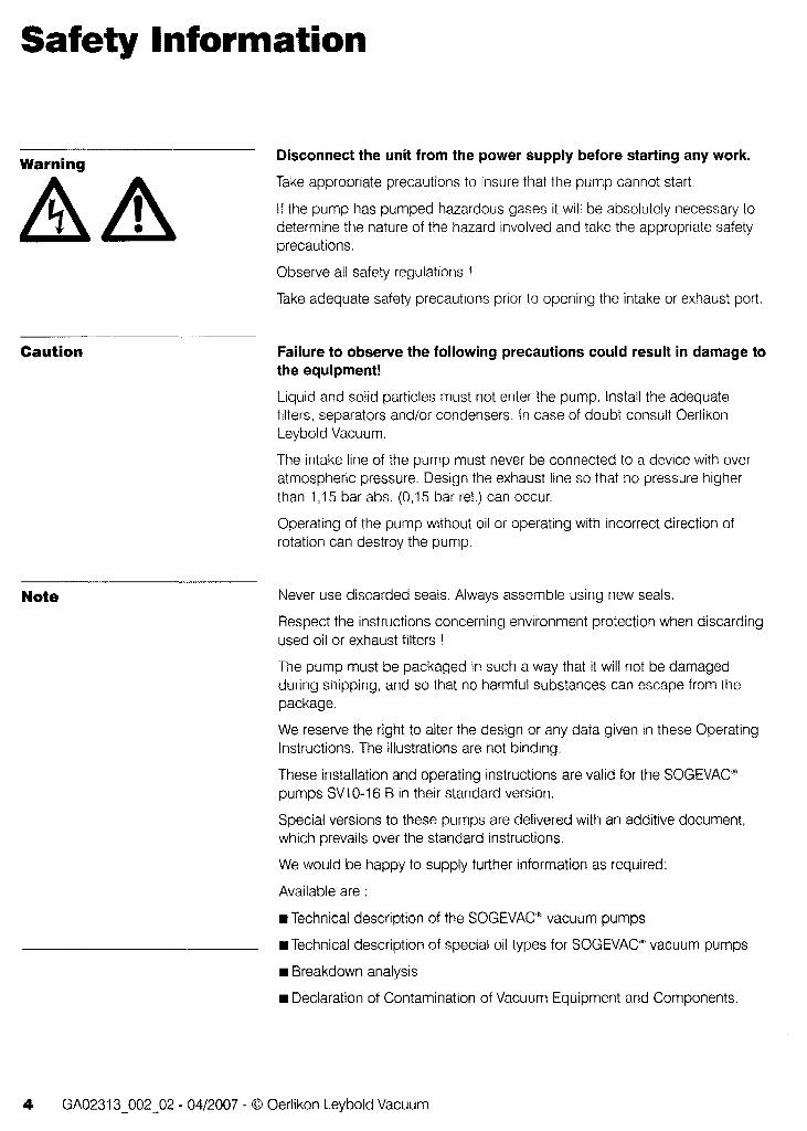
Spare parts
7 Spare parts To guarantee safe operation of the Oerlikon Leybold Vacuum vacuum pump, only original spare parts and accessories should be used. When ordering spare parts and accessories, always state pump type and serial number. You can find part numbers in the spare parts list.
Consummables and main spare parts kits for SOGEVAC~' pumps are usually available on stock at Oerlikon Leybold Vacuum's service centers. The list of these parts is given here after and in the spare parts table where the contents of each kits is detailed.
• Exhaust demisters 714 13 280
• Oil GS 32 (Special oils please refer to the specific notice of the pump or contact Oerlikon Leybold Vacuum).
• Service kit 9 71444430
• Set of seals 714 22 220
• Repair kit 714 22 230
We recommend to use these kits which have been defined to allow an optimal maintenance or repair. individual spare parts may need longer delivery time.
Repairs requiring the replacement of the stator or the rear end plate should be made by the Oerlikon Leybold Vacuum Service.
18 GA02313_002_02 - 04/2007 - © Oerlikon Leybold Vacuum

..." o G) e; I\)
w
.....
W
10
o I\
)
10
I\
)
o .j:>.
~
o -..I
@
o (1)
:::l
. §'
:::l ~
0- o 0: ~ c c :3
== cp ,.
... '--
... ' .. '
[SV1()
B =SV
16 S
] 199
19h
t
In
-a '" .. CD
-a
I» :I en

Spare parts
ERSA mEILLISTE f SPARES LIST f USTE DES PIECES DE RECHANGE SV10 B I SV16 B SIUck Abmessungen !mm), Werl<sloff Beslell-Nr
POS Oty BENENNUNG SPECIFICATION DESIGNATION Dimensions (mm), Material Ref. No. Remarques eM Dimensions (mm). matiere N'de Ref.
1 2 ROCKSICHERUNGSSCHRAUBE NON RETURN SCREW UNIT VIS ANTI·RETOUR ENS. 71416500 • 2 3 FLACHDICHTUNG FLAT GASKET JOINT PLAT 8,5X12Xl CU 71413460 • 3 1 GB LEITUNG EINHEIT G-B PIPE UNIT CANALISATION L-A ENS 71415000 4 1 FILTER VK31/2 FILTER VK 31/2 FILTRE VK31/2 71414970 •• 5 1 GB LEITUNG + FILTER G·B PIPE + FILTER CANALISATION L-A+FILTRE 71415330 Incl.l,2,3,4 6 1 SCHRAUBE SCREW VIS CHC MaXI 0 08,8 ZN 71417620 Incl.2 7 2 SCHRAUBE SCREW VIS CHC M6 X 25 08,8 ZC V3811415 8 1 SCHRAUBE SCREW VIS HM6X806,8 ZC V3802402 9 1 LAGERDECKEL FRONT END-PLATE FLASOUE AVANT 71418460 Incl.8 10 1 ANKER ROTOR ROTOR 71413100
11 1 SAIT 3 SCHIEBER SET 3 VANES ~EU DE 3 PALETTES 71413150 • 12 2 SCHRAUBE SCREW VIS CHC M8 X 85 08,8 V3810531 13 2 O·RING O·RING JOINT TOR 6,02 X 2,62 70SH FKM 71237600 • 14 2 O·RING O-RING ~OINT TOR 70 X 2,5 70SH NBR 71413470 • 15 1 PUMPENRING SV10 B PUMP CYLINDER SV10 B STATOR SV10 B 71418380 15 1 PUMPENRING SV16 B PUMP CYLINDER SVI 6 B STATOR SV16 B 71418450 16 1 VENTILPLA TTE VALVE PLATE LAME 71416370 • 17 1 VENTILANSCHLAG VALVE STOP CONTRE LAME 71416360 • 18 2 SCHRAUBE SCREW VIS CHC M6Xl0 08,8 V3811405 19 1 VOIR PAGE SUIVANTE I SEE NEXT PAGE I SEIHE ANDERE SEITE 20 1 PLATTE SUPPORTING PLATE TOLE SUPPORT 71415300 21 2 SCHRAUBE SCREW VIS HC M6 X 12 08.8 ZC 71418660 22 2 SCHEIBE WASHER RONDELLE W6 ZC V3600425 23 2 GUMMIFUSS RUBBER MOUNT AMORTISSEUR D20X15 F·F M8 71418670 24 6 SCHRAUBE SCREW VIS HM6X16Q6,8 ZC V3802411 25 2 GUMMIFUSS RUBBER MOUNT AMORTISSEUR D20X15 71414030 26 1 SAUGSTUTZEN FEDER INLET SPRING RESSORT ASPIRATION 71415640 27 1 ANSAUGVENTIL ANTI SUCKBACK VALVE K;LAPET ASPIRATION 71042990 • 2B 2 O-RING O-RING ~OINTTOR ;J4,52X3,53 70SH FKM 71417660 • 29 1 ANSAUGZWISCHENSTOCK INLET ADAPTER ENTRETOISE ASPIRATION 71413110 30 1 SAUGSTUTZEN FILTER DIRTTRAP FILTRE EMBOUTI ASPIRATION 71413440 31 1 ANSAUGFLANSCH INLET FLANGE BRIDE ASPIRATION 71413120 32 8 SCHEIBE WASHER RONDELLE M6 ZC V3600401 33 4 SCHRAUBE SCREW VIS HM6X3S06,8 V3B02419 34 2 MUTTER NUT ECROU HMS06 ZC VI500501 35 2 SCHEIBE WASHER RONDELLE WB ZC V36OO524 36 1 FLACHDICHTUNG FLAT GASKET ~OINT CARTER STATOR 71416430 • 37 1 BLECHSCHRAUBE SHEET METAL SCREW VISA TOLE CL N 10-19 TYPE P V3835710 38 1 SCHEIBE WASHER RONDELLE L5 ZC V3600305 39 1 AUSPUFFMEMBRANE EXHAUST MEMBRANE MEMBRANE D'ECHAPPEMENT 71413170 40 1 AUSPUFFfLANSCH FLANGE EXHAUST BRIDE REFOULEMENT 71413160 41 1 SCHRAUBE SCREW VIS C M4X16 05.6 CRY ZN V3827310 42 1 IAUSPUFF FILTER FEDERBLATT FRICTION SPRING CARTRIDGE LAME RESSORT CARTOUCHE ENS 71413270 •• 43 1 AUSPUFF-FILTER EXHAUST FILTER CARTOUCHE 71413280 •• 44 1 OLROCKFOHRUNGSFIL TER OIL RETURN FILTER FILTRE RECUPERATION 71416440 •• 45 1 FLACHDICHTUNG AUSLASS FLAT GASKET OUTLET JOINT REFOULEMENT 71413240 • • 46 2 STOPFEN+ O-RING PLUG + O-RING BOUCHON FENDU· G314 71256380 Incl.47 47 2 O-RING O-RING JOINTTOR 27 X 2,5 NBR 71036720 • • 48 1 OELSCHAUGLAS OIL SIGHT GLASS VOYANT D'HUILE G314 71212420 • 49 1 OELKASTEN OIL CASING CARTER D'HUILE 71416410 Incl.49a 49a 2 BOllEN LOCKING SCREW GOUJON M8-25115J~12 06,8 V2100425 50 1 O-RING O-RING JOINT TOR aX3 FKM 71217590 • 51 1 REDUZIERSTUCK + O-RING REDUCTION + O-RING REDUCTION + JOINT G 3/4-G 1/2 95124
-DICHTUNGSSATZ SET OF SEALS JEU DE JOINTS 71422220 Incl. • I-REPARATUR KIT REPAIR KIT KIT REPARATION 71422230 Inc!. WARTUNGSSATZ SERVICE KIT KIT DE MAINTENANCE 971444430 Incl.
GA02313~002~02 - 04/2007 - © Oerlikon Leybold Vacuum 21
II)
II)
G) » 0 I\.)
w
->
-
,w
0 0 ,I\.
)
0 I\.)
0 ~ ---I\
.)
0 0 ......
@
0 (1)
::::!.. ~
0 ::::J r (1)
'<
0-
0 0:: Of 0 c c 3
=
'!2 • r'
... ' ....
..... 13
14
5
51
/50
./,33
lit::
!~
~:
,;:
~~
,
1 sv
1-6 B-
~SV-
16-B
-]
15
14
19a
22
20
25
t
en " I»
.. CD " I» :s C
I)

pas
19
19a 19b 19c 19d 1ge 191
199 19h
19
1ge 191
199 19h
19
1ge 191 199 19h
19
1ge 191
199 19h 19i
19
1ge 191 199 19h 19i
19
1ge
191 199 19h 19i
19
1ge 19
199 19h 19i
StOck Oty BENENNUNG SPECIFICATION DESIGNATION O!e 1 MOTOA EUA 1 USA 3PH MOTOR EUR 1 USA 3PH MOTEUR EUR 1 USA 3PH
1 HINTEREN LAGERDECKEL END BEARING PLATE FLASQUE ARRIERE 1 RADIAL DICHTRING RADIAL SHAFT SEAL JOINT A LEVR E 1 KUGELLAGER BALL BEAR ING ROULEMENT 1 PASS·FEDER KEY CLAVETIE 1 KLEMMENKASTEN TERMINAL BOX BOlTE A BaRNES 1 KLEMMENBRETT TERMINAL BOARD BORNIER 1 LUEFTER FAN VENTILATEUR MOTEUR I LUEFTERHAUBE -AN COVER CAPOT MOTEUR 1 MOTOR JAPAN 3PH MOTOR JAPAN 3PH MOTEUR JAPaN 3PH
1 KLEMMENKASTEN TERMINAL BOX BOlTE A BORNES 1 KLEMMENBRETI TERMINAL BOARD BORNIER 1 LUEFTER FAN VENTILATEUR MOTEUR 1 LUEFTERHAUBE FAN COVER CAPOT MOTEUR 1 MOTOR EUR 1 USA 3PH CCC MOTOR EUR 1 USA 3PH CCC MOTEUR EUR I USA 3PH cec
1 KLEMMENKASTEN TERMINAL BOX BOlTE A BORNES 1 KLEMMENBRETI TERMINAL BOARD BORNIER 1 LUEFTER FAN VENTILATEUR MOTEUR 1 LUEFTERHAUBE FAN COVER CAPOT MOTEUR
1 ~TOREURIPH MOTOR EUR 1 PH MOTEUR EUR lPH
1 KLEMMENKASTEN ERMINAL BOX BOlTE A BaRNES 1 KLEMMENBRETI TERMINAL BOARD BORNIER 1 LUEFTER FAN VENTILATEUR MOTEUR 1 LUEFTERHAUBE FAN COVER CAPaT MOTEUR
KONDENSATOR CAPACITOR CONDENSATEUR 1 MOTOR USA lPH MOTOR USA lPH MOTEUR USA lPH
1 KLEMMENKASTEN TERMINAL BOX BOlTE A BORNES 1 KLEMMENBRETT TERMINAL BOARD BORNIER 1 LUEFTER FAN VENTILATEUR MOTEUR 1 LUEFTERHAUBE FAN COVER CAPOT MOTEUR
KONDENSATOR CAPACITOR CONDENSATEUR 1 MOTOR JAPAN 1 PH MOTOR JAPAN lPH MOTEUR JAPON 1 PH
1 KLEMMENKASTEN TERMINAL BOX BOlTE A BaRNES 1 KLEMMENBRETI TERMINAL BOARD BORNIER 1 LUEFTER FAN VENTILATEUR MOTEUR 1 LUEFTERHAUBE FAN COVER CAPOT MOTEUR
KONDENSATOR CAPACITOR CONDENSATEUR 1 ~OTOR EUR lPH CCC MOTOR EUR lPH CCC MOTEUR EUR 1 PH CCC
1 KLEMMENKASTEN [ERMINAL BOX BOlTE A BaRNES 1 KLEMMENBRETT ITERMINAL BOARD BORNIER 1 LUEFTER FAN VENTILATEUR MOTEUR 1 LUEFTERHAUBE FAN COVER CAPOT MOTEUR
KONDENSATOR CAPACITOR CONDENSATEUR
DICHTUNGSSATZ SET OF SEALS JEU DE JOINTS
* Immer das Kugellager wechseln, wenn der Wellendichtring ausgetauscht wird. * Always change the ball bearing when changing the shalt seal. * Remplacer obligatoirement Ie roulement IDrS du remplacement du joint a havre.
Spare parts
Abmessungen (mm), Werkstoff !lestell·Nr Dimensions (mm), Malerial Ref. No. Remarques Dimensions (mrn')", matiere Woo Ret.
0,55 kW it 50 Ht I 0,65 kW II 60 Hz 71415050 IncI.19a,b,c,d,e,f,g,h 220·2401380·415 V+·l0 %; 50 Hz 220·2661380·460 V+·l0 %; 60 Hz
71413490 DNI7X30X6 71421560 • • DN17X4OX12 71421550
5X5X30 71415200 971444340 71422210 71421530 71421540
0,55 kW il50 Hz 1 0,65 kW II 60 Hz 71415070 IncI.19a,b,c,d,e,f,g,h 200V+ 10 %·15%' 50 & 60 Hz
971444410 71422210 71421530 71421540
O,SS kW II 50 Hz I 0,65 kW II 60 Hz 971451240 Incl.19a,b,c,d,e,f,g,h 220·2401380·415 V+·l0 %; 50 Hz 220·2561380·460 V.· 10 %; 60 Hz
971444340 71422210 71421530 71421540
0,55 kW a so Hz 1 0,65 kW II 60 Hz 71413770 IncI.19a.b,c,d,e,l,g,h,i 230 V+· 10 %. 50 & 60 Hz
971444360 971444350 971444360 971444370
16 ~F 971444390 p,65 kW a 60 Hz 71413940 1nc1.19a,b,c,d,e,g,f,h,i 110 ·120 V+·l0%· 60 Hz
971444410 971444350 971444360 971444370
110 ~F 971444400 0,55 kW II 50 Hz 1 0,65 kW • 60 Hz 71415040 Incl.l9a,b,c,d,e,t,g,h,i l00V+ 10%·15%'50&60 Hz
971444410 971444350 971444360 971444370
110 ~F 971444400 O,SS kW II 50 Hz I 0,65 kW II 60 Hz 971451230 IncI.19a,b,c,d,e,l,g,h,i
30 V+·l0 %. 50 & 60 Hz 971444380 971444350 971444360 971444370
16 ~F E6500533
" 71422220 Incl.
GA02313~002~02 - 04/2007 - © Oerlikon Leybold Vacuum 23