Embed Size (px)
Citation preview
BULETIN ŞTIINŢIFIC, Seria C, Fascicola: Mecanică, Tribologie, Tehnologia Construcţiilor de Maşini SCIENTIFIC BULLETIN, Serie C, Fascicle: Mechanics, Tribology, Machine Manufacturing Technology, ISSN 1224-3264, Volume 2016 No.XXX
75
Software Tool Used in CAPP/CAM Systems for Rotational Parts
Gheorghe Oancea1*, Sever-Alexandru Haba2
Abstract: Nowadays the manufacturing technologies play an important role in production process. To manufacture in a short time, at the requested quality, with minimum resources is a target for any industrial company. A way to reach this objective is to use commercial software systems in combination with software tools developed for a specific application. In this direction, the integration of CAPP with CAD and CAM is a possibility to obtain the technological documentation in a short time. This paper presents a new software tool which allows to the user to obtain the manufacturing sequences, cutting data for each process from the manufacturing sequence and finally to assist at the simulation of each process. It is conceived by the authors in Visual LISP and for the interface OpenDCL is used. The tool is very useful in the integration process of CAPP with CAM system for rotational parts. Keywords: CAD/CAPP/CAM systems, Software tool, Machining sequences, Cutting process, Cutting parameters, Rotational surfaces 1 INTRODUCTION
It is well-known that the integration of CAD/CAPP/CAM systems is an objective for industrial companies because it has as final effect obtaining a short production cycle with financial benefits [11]. The CAPP is a bridge between CAD and CAM and its role is to interpret and process the information obtained from the design stage in terms of features, shape, tolerances, positions, relationship with other geometry and to determine the manufacturing operation instructions necessary to obtain technological information and transfer it in the CAM system [10]. The CAPP system has to transform the design specifications into manufacturing instructions [5]. Because of its importance sometimes it is considered a bottleneck of CAD/CAPP/CAM integration [1]. In a CAPP system after the process and manufacturing sequence selection based on the manufacturing features, the determination of optimum process parameters is very important because it influences the cost and quality of the finished part [5].
In practice there are two categories of CAPP systems: variant and generative [5]. The variant CAPP systems are based on group technology (GT) concept [5] and uses coding and classification to identify the manufacturing sequences for a particular part from the generalized part of the family [7]. Generative CAPP system has the capability to obtain the manufacturing process plan for the new part, analyzing the part geometry, the material and primary technological parameters that may influence the manufacturing decision [5].
An example of integration CAD, CAPP and CAM system is SIIRoD system [2, 3]. It is a software system that enables simultaneous and integrated approach of the design, process planning and manufacturing processes for parts of spur gears family. The CAPP system allows establishing for each simple or complex feature the machining sequence (optimum machining technological procedures) ever since CAD
phase, before the part to be completely defined from geometrically point of view.
For each machining method, the machining allowance, number of passes, cutting parameters, machining time and estimated cost, are calculated. This approach allows analysing the machining time and estimating the cost for different machining process, machine tools and cutting tools. Since CAD phase the best decisions regarding process planning and manufacturing, can be taken. After finishing the part from constructive point of view, can be, in a short time, obtained the final technological documentation by a simple reordering of technological sequences and then technological documentation (process plan and final CNC files) [2, 3].
Not in all the cases the machining process information obtained in the CAPP system can be directly interpreted and transferred in CAM systems [11] and later used in the manufacturing process simulation.
Fig.1. First friendly contact between the users and the
software tool
BULETIN ŞTIINŢIFIC, Seria C, Fascicola: Mecanică, Tribologie, Tehnologia Construcţiilor de Maşini SCIENTIFIC BULLETIN, Serie C, Fascicle: Mechanics, Tribology, Machine Manufacturing Technology, ISSN 1224-3264, Volume 2016 No.XXX
76
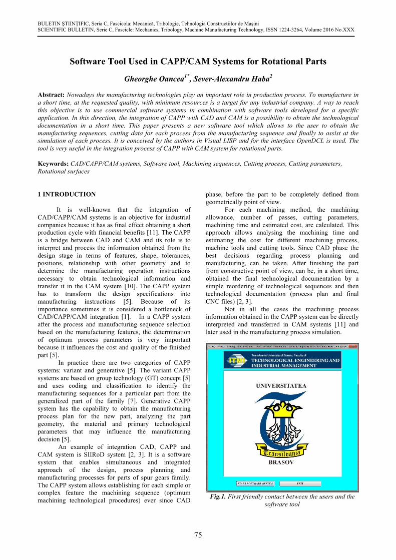
Fig.2. Example of dialog boxed used in the software
A possibility to make a unique connexion
between objects and the associated geometrical and non-geometrical properties is to integrate data in a common database, where constructive and manufacturing data can be easily handled [6].
The present paper describes a software tool which can be easy integrated in CAPP and CAM systems. It allows to the user, based on data inputted, to be determined the manufacturing sequences for specific surfaces, to compute the manufacturing parameters according to the selected machine tools and cutting tools, and to simulate the manufacturing processes.
Fig.3. Error message - user overwrite correct value in
the coloured area
2 SOFTWARE TOOL PRESENTATION
The software tool was written in Visual LISP programming environment [9] and uses the Open DCL facilities for the graphical user interface.
The dialog is a friendly one and it uses different types of dialog boxes from simple one (Fig. 1, Fig 2. and Fig. 3) to complex (Fig. 4 and Fig. 5). The errors are also handled by the software tool; the user is informed when an error appears and he can directly overwrite the correct value in the area with error (Fig. 3).
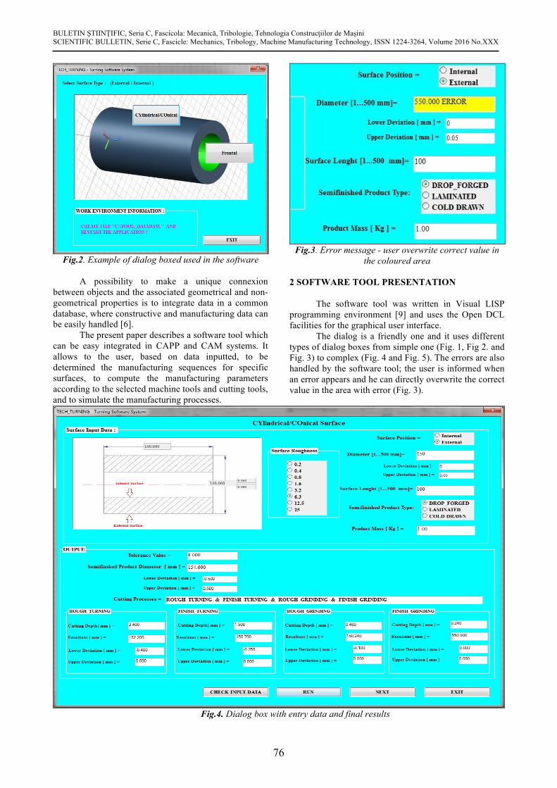
Fig.4. Dialog box with entry data and final results
BULETIN ŞTIINŢIFIC, Seria C, Fascicola: Mecanică, Tribologie, Tehnologia Construcţiilor de Maşini SCIENTIFIC BULLETIN, Serie C, Fascicle: Mechanics, Tribology, Machine Manufacturing Technology, ISSN 1224-3264, Volume 2016 No.XXX
77
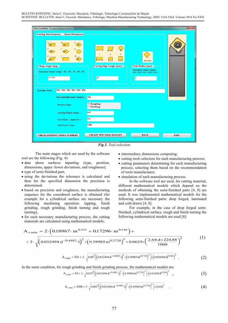
Fig.5. Tool selection
The main stages which are used by the software tool are the following (Fig. 4): • data about surfaces inputting (type, position,
dimensions, upper /lower deviations, and roughness); • type of semi-finished part; • using the deviations the tolerance is calculated and
then for the specified dimension the precision is determined;
• based on precision and roughness, the manufacturing sequence for the considered surface is obtained (for example for a cylindrical surface are necessary the following machining operation: lapping, finish grinding, rough grinding, finish turning and rough turning);
• for each necessary manufacturing process, the cutting materials are calculated using mathematical models;
• intermediary dimensions computing; • cutting tools selection for each manufacturing process; • cutting parameters determining for each manufacturing
process, selecting them based on the recommendation of tools manufacturer;
• simulation of each manufacturing process. In the software tool are used, for cutting material,
different mathematical models which depend on the methods of obtaining the semi-finished parts [4, 8] are used. It was implemented mathematical models for the following semi-finished parts: drop forged, laminated and cold drawn [4, 8].
For example, in the case of drop forged semi-finished, cylindrical surface, rough and finish turning the following mathematical models are used [8]:
( )( ) ( )
A m mc
d l m d
min. .
. .
. .
. . . . .
= × × + × +
æèç
öø÷+ × × × + × + +
× +-
2 010967 0172960 231 0146
0 4482 2 0 2728 22
2 0 032494 0 39985 0 0625 2 64 224 881000
(1)
( ) ( ) ( )A d m dc lmin. . .. . . . .= + × × × + ×
æèç
öø÷+ ×-0 4 2 0 062 0 032494 0 39985 0 0205680 4482 2 0 2728 2 0 366 2 . (2)
In the same condition, for rough grinding and finish grinding process, the mathematical models are:
( ) ( ) ( )A d m dc lmin. . .. . . . .= + × × × + ×
æèç
öø÷+ ×-01 2 0 0252 0 032494 0 39985 0 010280 4482 2 0 2728 2 0 366 2 , (3)
( ) ( ) ( )A d mc lmin. .. . . . .= + × × × + ×
æèç
öø÷+-0 06 2 0 0032 0 032494 0 39985 0 040 4482 2 0 2728 2 2 . (4)
BULETIN ŞTIINŢIFIC, Seria C, Fascicola: Mecanică, Tribologie, Tehnologia Construcţiilor de Maşini SCIENTIFIC BULLETIN, Serie C, Fascicle: Mechanics, Tribology, Machine Manufacturing Technology, ISSN 1224-3264, Volume 2016 No.XXX
78
In the relation (1), (2), (3) and (4) the symbols have the following meanings:
• Acmin is the minimum cutting material at the current cutting process;
• m is the mass of the part; • d is the cutting diameter; • l is the cutting length.
The nominal cutting material is determined by the relation [4]:
A A Tcnom c p= +min , (5) .where Tp is the machining tolerance previous operation.
The intermediary dimensions are calculated for each surface from the finished part which has to be machined.
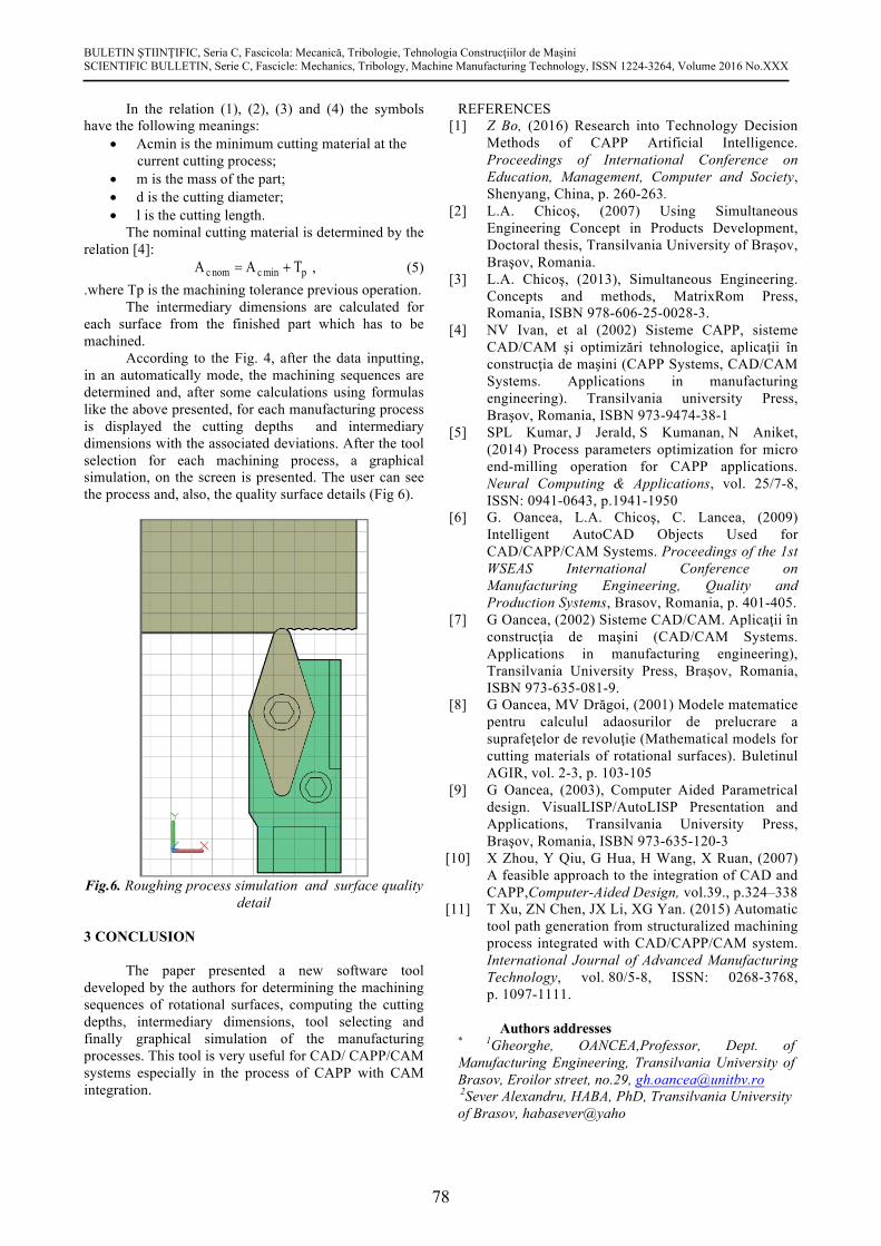
According to the Fig. 4, after the data inputting, in an automatically mode, the machining sequences are determined and, after some calculations using formulas like the above presented, for each manufacturing process is displayed the cutting depths and intermediary dimensions with the associated deviations. After the tool selection for each machining process, a graphical simulation, on the screen is presented. The user can see the process and, also, the quality surface details (Fig 6).
Fig.6. Roughing process simulation and surface quality
detail
3 CONCLUSION The paper presented a new software tool
developed by the authors for determining the machining sequences of rotational surfaces, computing the cutting depths, intermediary dimensions, tool selecting and finally graphical simulation of the manufacturing processes. This tool is very useful for CAD/ CAPP/CAM systems especially in the process of CAPP with CAM integration.
REFERENCES [1] Z Bo, (2016) Research into Technology Decision
Methods of CAPP Artificial Intelligence. Proceedings of International Conference on Education, Management, Computer and Society, Shenyang, China, p. 260-263.
[2] L.A. Chicoş, (2007) Using Simultaneous Engineering Concept in Products Development, Doctoral thesis, Transilvania University of Braşov, Braşov, Romania.
[3] L.A. Chicoş, (2013), Simultaneous Engineering. Concepts and methods, MatrixRom Press, Romania, ISBN 978-606-25-0028-3.
[4] NV Ivan, et al (2002) Sisteme CAPP, sisteme CAD/CAM şi optimizări tehnologice, aplicaţii în construcţia de maşini (CAPP Systems, CAD/CAM Systems. Applications in manufacturing engineering). Transilvania university Press, Braşov, Romania, ISBN 973-9474-38-1
[5] SPL Kumar, J Jerald, S Kumanan, N Aniket, (2014) Process parameters optimization for micro end-milling operation for CAPP applications. Neural Computing & Applications, vol. 25/7-8, ISSN: 0941-0643, p.1941-1950
[6] G. Oancea, L.A. Chicoş, C. Lancea, (2009) Intelligent AutoCAD Objects Used for CAD/CAPP/CAM Systems. Proceedings of the 1st WSEAS International Conference on Manufacturing Engineering, Quality and Production Systems, Brasov, Romania, p. 401-405.
[7] G Oancea, (2002) Sisteme CAD/CAM. Aplicaţii în construcţia de maşini (CAD/CAM Systems. Applications in manufacturing engineering), Transilvania University Press, Braşov, Romania, ISBN 973-635-081-9.
[8] G Oancea, MV Drăgoi, (2001) Modele matematice pentru calculul adaosurilor de prelucrare a suprafeţelor de revoluţie (Mathematical models for cutting materials of rotational surfaces). Buletinul AGIR, vol. 2-3, p. 103-105
[9] G Oancea, (2003), Computer Aided Parametrical design. VisualLISP/AutoLISP Presentation and Applications, Transilvania University Press, Braşov, Romania, ISBN 973-635-120-3
[10] X Zhou, Y Qiu, G Hua, H Wang, X Ruan, (2007) A feasible approach to the integration of CAD and CAPP,Computer-Aided Design, vol.39., p.324–338
[11] T Xu, ZN Chen, JX Li, XG Yan. (2015) Automatic tool path generation from structuralized machining process integrated with CAD/CAPP/CAM system. International Journal of Advanced Manufacturing Technology, vol. 80/5-8, ISSN: 0268-3768, p. 1097-1111.
Authors addresses
* 1Gheorghe, OANCEA,Professor, Dept. of Manufacturing Engineering, Transilvania University of Brasov, Eroilor street, no.29, [email protected] 2Sever Alexandru, HABA, PhD, Transilvania University of Brasov, habasever@yaho