Embed Size (px)
Citation preview
Software Testing and ReliabilityTesting Graphical User Interfaces
Aditya P. MathurPurdue UniversityMay 19-23, 2003
@ Guidant CorporationMinneapolis/St Paul, MN
Graduate Assistants: Ramkumar NatarajanBaskar Sridharan
Last update: April 17, 2003
Software Reliability © Aditya P. Mathur 2003 2
References
2. Generating test cases for GUI responsibilities using complete interaction sequences, Lee White and Husain Almezen, International Symposium on Software Reliability Engineering, San Jose, CA, pp. 110-121, October 2000.
3. User-based testing of GUI sequences and their interactions, Lee White,Husain Almezen, and Nasser Alzeidi
1. Regression Testing of GUI Event-Interactions, Lee White, Proc. of the International Conference on Software Maintenance, Washington DC, pp. 350-358, November 1996.
Material from 1. and 2. is used extensively in this presentation.
Software Reliability © Aditya P. Mathur 2003 3
References [contd.]
6. Orthogonal Latin Squares, Alexander Bogomolny, http://www.cut-the-knot.com/arithmetic/latin3.shtml
4. Hierarchical GUI test case generation using automated planning. Atif Memon, Martha E. Pollack, Mary Lou Soffa, IEEE Transactions on Software Engineering, V27, N 2, February 2001, pp144-155.
5. Coverage criteria for GUI testing, Atif Memon, Mary Lou Soffa, and Martha E. Pollack, , 8th European Conference and 9th ACM SIGSOFT Foundation of Software Engineering (FSE-9), Austria, September 10-14, 2001.
Software Reliability © Aditya P. Mathur 2003 4
References [contd.]
7. Model Checking Graphical User Interfaces Using Abstractions, Matthew B. Dwyer, Vicki Carr, Laura Hines, Proceedings of the Sixth European Software Engineering Conference (ESEC/FSE 97), September 1997.
8. The Black Art of GUI Testing, Lawrence Kepple, Dr. Dobb’s Journal, pp. 40-46, Feb. 1994.
Software Reliability © Aditya P. Mathur 2003 5
GUI Testing
Learning objectives-
1. GUI test tools: strengths and weaknesses
2. Modeling and test generation for GUI testing
3. Automated test oracles for GUI testing
4. Coverage Criteria for GUI testing
2. Why is GUI testing difficult?
Software Reliability © Aditya P. Mathur 2003 6
GUI Testing: Questions
What types of GUI test tools are available?
Are there formal techniques for testing GUIs? If so, then what are they and how well do they function?
What are the advantages and drawbacks of capture-replay techniques and ho can one do better?
What makes GUI testing difficult?

Software Reliability © Aditya P. Mathur 2003 7
Features of GUI Test Tools
Record and playback of physical events
Screen image capture and comparison
Shell scripts to control and execute test runs of the GUI
We focus on how to test interactions amongst GUI objects.
Software Reliability © Aditya P. Mathur 2003 8
GUI Testing: Techniques
Pair-wise testing of GUI interactions. [Due to Lee White.]
Testing GUIs using Complete Interaction Sequences corresponding to responsibilities. [Due to Lee White, and Husain Almezen.]
Software Reliability © Aditya P. Mathur 2003 9
GUI Interaction Testing
Testing for interactions amongst all GUI objects.
Problem: How to automatically and efficiently devise tests for testing pair wise interactions amongst GUI objects?
GUI interactions: Static, Dynamic, and a mix of the two.
Software Reliability © Aditya P. Mathur 2003 10
Sample GUI Options
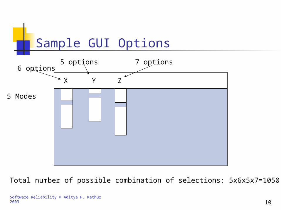
Total number of possible combination of selections: 5x6x5x7=1050
6 options5 options 7 options
5 Modes
X Y Z
Software Reliability © Aditya P. Mathur 2003 11
Testing Static Interactions
In the previous example, there is a total of 1050 pair wise interactions.
Can we reduce the number of pair wise tests and if so then how ?
Testing is considered static in this example because only a single screen is involved.
There are too many higher order interactions. At present we focus only on testing second order, or pair wise, interactions.
Software Reliability © Aditya P. Mathur 2003 12
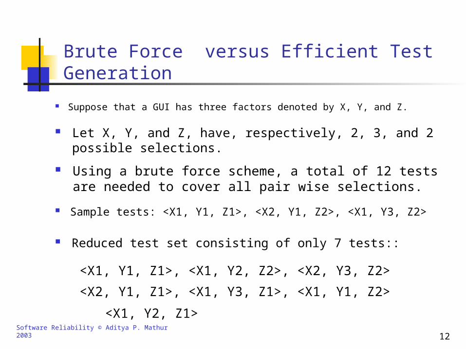
Brute Force versus Efficient Test Generation
Suppose that a GUI has three factors denoted by X, Y, and Z.
Let X, Y, and Z, have, respectively, 2, 3, and 2 possible selections.
Using a brute force scheme, a total of 12 tests are needed to cover all pair wise selections.
Sample tests: <X1, Y1, Z1>, <X2, Y1, Z2>, <X1, Y3, Z2>
Reduced test set consisting of only 7 tests::
<X1, Y1, Z1>, <X1, Y2, Z2>, <X2, Y3, Z2>
<X2, Y1, Z1>, <X1, Y3, Z1>, <X1, Y1, Z2>
<X1, Y2, Z1>
Software Reliability © Aditya P. Mathur 2003 13
Controlling the number of possible interactions
In both static and dynamic cases, the number of possible interactions could be very large.
In the dynamic case a selection might bring up a new screen where additional selections are made.
One method to tackle the combinatorial growth was proposed by Dalal [1994].
Software Reliability © Aditya P. Mathur 2003 14
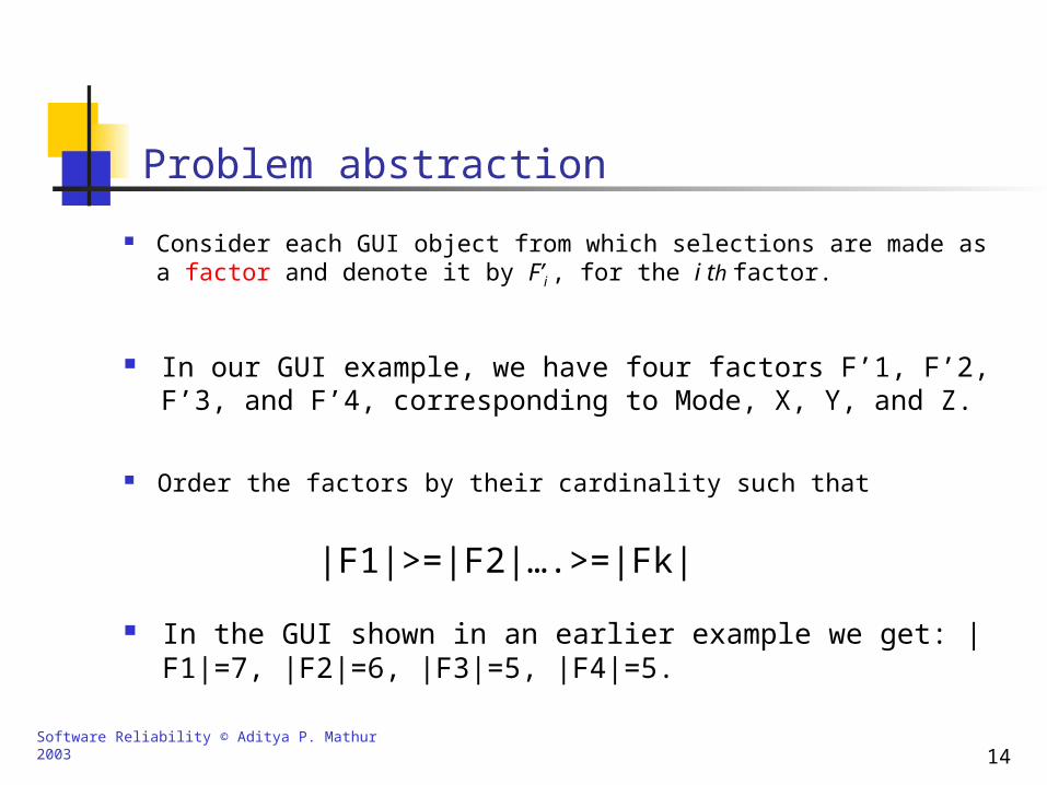
Problem abstraction
Consider each GUI object from which selections are made as a factor and denote it by F’i , for the i th factor.
In our GUI example, we have four factors F’1, F’2, F’3, and F’4, corresponding to Mode, X, Y, and Z.
Order the factors by their cardinality such that
In the GUI shown in an earlier example we get: |F1|=7, |F2|=6, |F3|=5, |F4|=5.
|F1|>=|F2|….>=|Fk|
Software Reliability © Aditya P. Mathur 2003 15
Problem Statement
Question: What is the lower bound on the number of tests?
The problem now is to select a set of tests each set consisting of one selection from each factor.
Software Reliability © Aditya P. Mathur 2003 16
Testing Dynamic Interactions
This involves making a selection from one or more menus, buttons, or any other GUI object on one screen.
Such a selection brings up a new screen where additional selections are made.
Assumption: Regardless of the selection made, the new screen is always dependent on the current screen and not on the entire past history.
Software Reliability © Aditya P. Mathur 2003 17
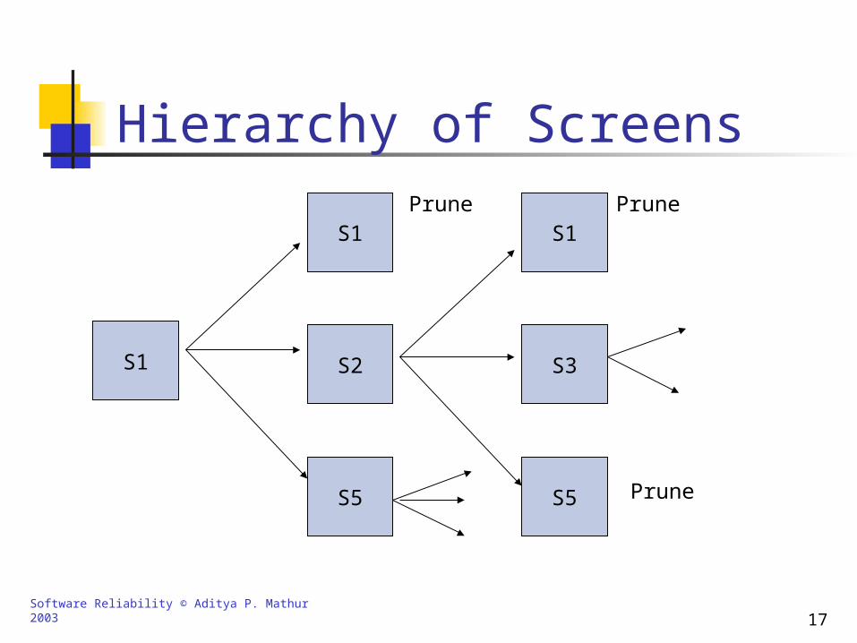
Hierarchy of Screens
S1
S1
S2
S5
S1
S3
S5
Prune Prune
Prune
Software Reliability © Aditya P. Mathur 2003 18
Pruning Paths Starting with the initial screen S1, generate a hierarchy where
each path of screen transitions ends at a pruned screen.
Select all paths from S1 to pruned screens but do not include the pruned screens.
With each selected path, associate only those GUI events which lead to the paths being selected.
Map these factors and selections onto the GUI Interaction test problem.
Software Reliability © Aditya P. Mathur 2003 19
Review: Selection of Test cases
The problem is to select a set of test cases, each test case consisting of one selection from each factor.
The lower bound on the number of tests is 7x6=42.
One can often get close to the lower bound.
Software Reliability © Aditya P. Mathur 2003 20
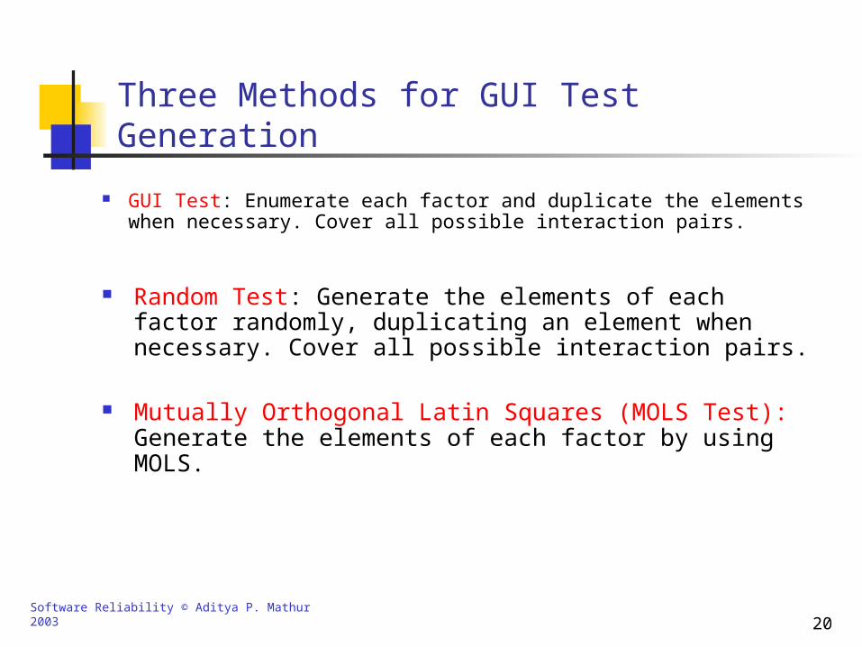
Three Methods for GUI Test Generation
GUI Test: Enumerate each factor and duplicate the elements when necessary. Cover all possible interaction pairs.
Random Test: Generate the elements of each factor randomly, duplicating an element when necessary. Cover all possible interaction pairs.
Mutually Orthogonal Latin Squares (MOLS Test): Generate the elements of each factor by using MOLS.
Software Reliability © Aditya P. Mathur 2003 21
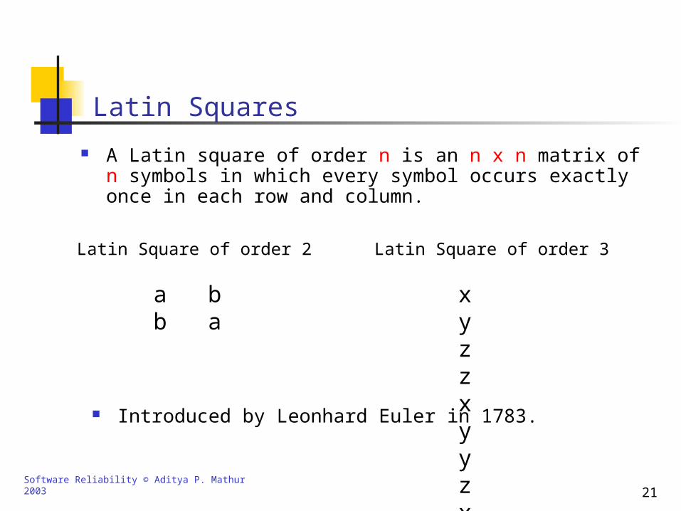
Latin Squares
A Latin square of order n is an n x n matrix of n symbols in which every symbol occurs exactly once in each row and column.
a bb a
Latin Square of order 2
x y zz x yy z x
Latin Square of order 3
Introduced by Leonhard Euler in 1783.
Software Reliability © Aditya P. Mathur 2003 22
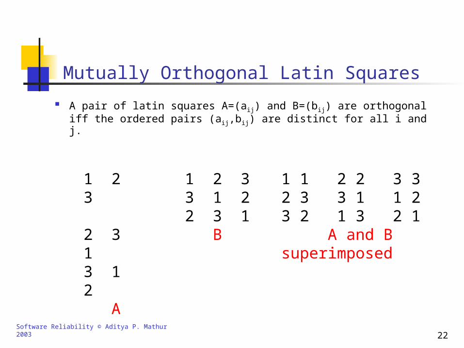
Mutually Orthogonal Latin Squares
A pair of latin squares A=(aij) and B=(bij) are orthogonal iff the ordered pairs (aij,bij) are distinct for all i and j.
1 2 3 2 3 1 3 1 2 A
1 2 33 1 22 3 1 B
1 1 2 2 3 32 3 3 1 1 23 2 1 3 2 1 A and Bsuperimposed
Software Reliability © Aditya P. Mathur 2003 23
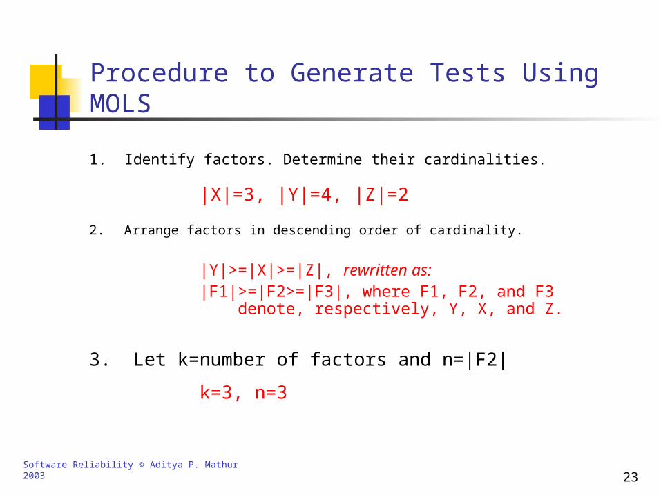
Procedure to Generate Tests Using MOLS
2. Arrange factors in descending order of cardinality.
|X|=3, |Y|=4, |Z|=2
1. Identify factors. Determine their cardinalities.
|Y|>=|X|>=|Z|, rewritten as:|F1|>=|F2>=|F3|, where F1, F2, and F3
denote, respectively, Y, X, and Z.
3. Let k=number of factors and n=|F2|
k=3, n=3

Software Reliability © Aditya P. Mathur 2003 24
Procedure to Generate Tests Using MOLS [Contd.]
4. Prepare a table containing k columns and k x n rows divided into |F1| blocks. Label columns as F1, F2, ..Fk.
F1 F2 F3
Block 1
Block 2
Block 3
Block 4
Software Reliability © Aditya P. Mathur 2003 25
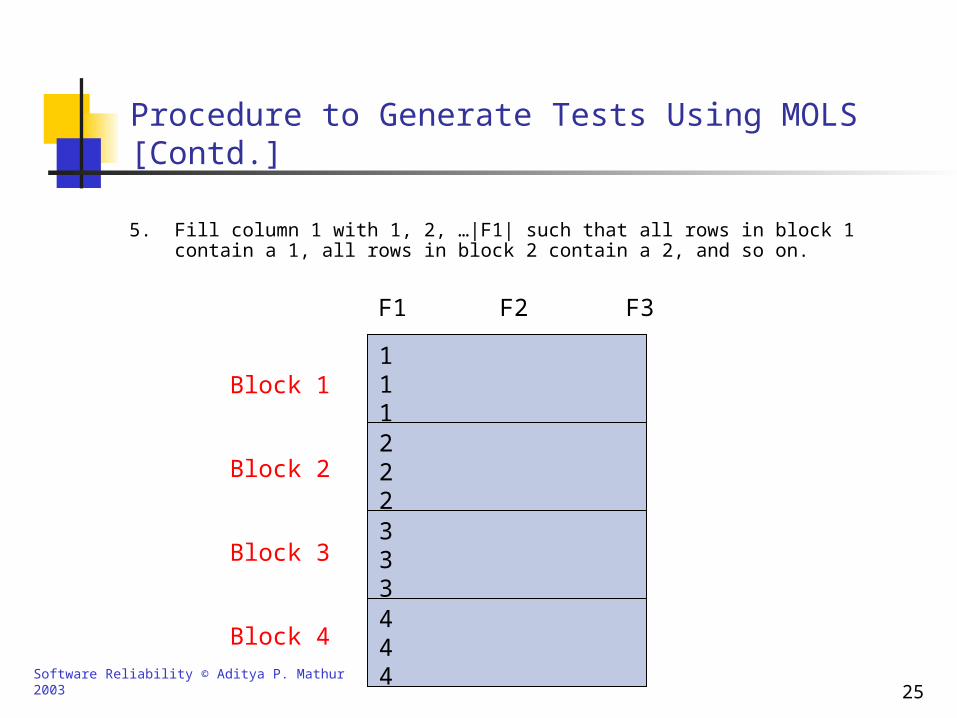
Procedure to Generate Tests Using MOLS [Contd.]
5. Fill column 1 with 1, 2, …|F1| such that all rows in block 1 contain a 1, all rows in block 2 contain a 2, and so on.
F1 F2 F3
444
111222333
Block 1
Block 2
Block 3
Block 4
Software Reliability © Aditya P. Mathur 2003 26
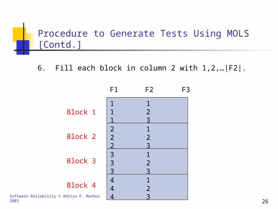
Procedure to Generate Tests Using MOLS [Contd.]
6. Fill each block in column 2 with 1,2,…|F2|.
F1 F2 F3
4
44
111222333
Block 1
Block 2
Block 3
Block 4
3
12
123123123
Software Reliability © Aditya P. Mathur 2003 27
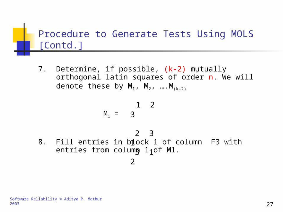
Procedure to Generate Tests Using MOLS [Contd.]
7. Determine, if possible, (k-2) mutually orthogonal latin squares of order n. We will denote these by M1, M2, ….M(k-2)
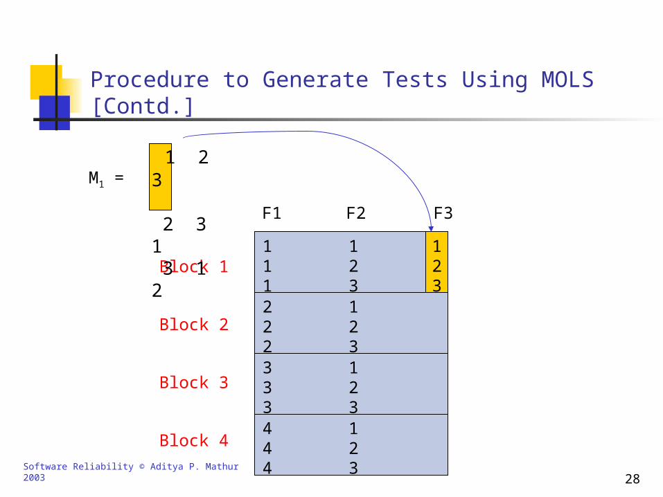
8. Fill entries in block 1 of column F3 with entries from column 1 of M1.
1 2 3 2 3 1 3 1 2
M1 =
Software Reliability © Aditya P. Mathur 2003 28
F1 F2 F3
4
44
111222333
Block 1
Block 2
Block 3
Block 4
3
12
123123123
Procedure to Generate Tests Using MOLS [Contd.]
1 2 3 2 3 1 3 1 2
M1 =
123
Software Reliability © Aditya P. Mathur 2003 29
Procedure to Generate Tests Using MOLS [Contd.]
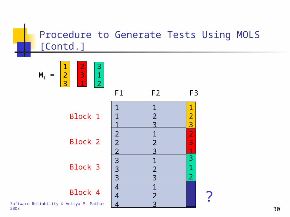
9. Fill entries in blocks 2 and 3 of column F3 with entries from columns 2 and 3 of M1.
Software Reliability © Aditya P. Mathur 2003 30
F1 F2 F3
4
44
111222333
Block 1
Block 2
Block 3
Block 4
3
12
123123123
Procedure to Generate Tests Using MOLS [Contd.]
M1 =123
231
312
123231312
?
Software Reliability © Aditya P. Mathur 2003 31
Procedure to Generate Tests Using MOLS [Contd.]
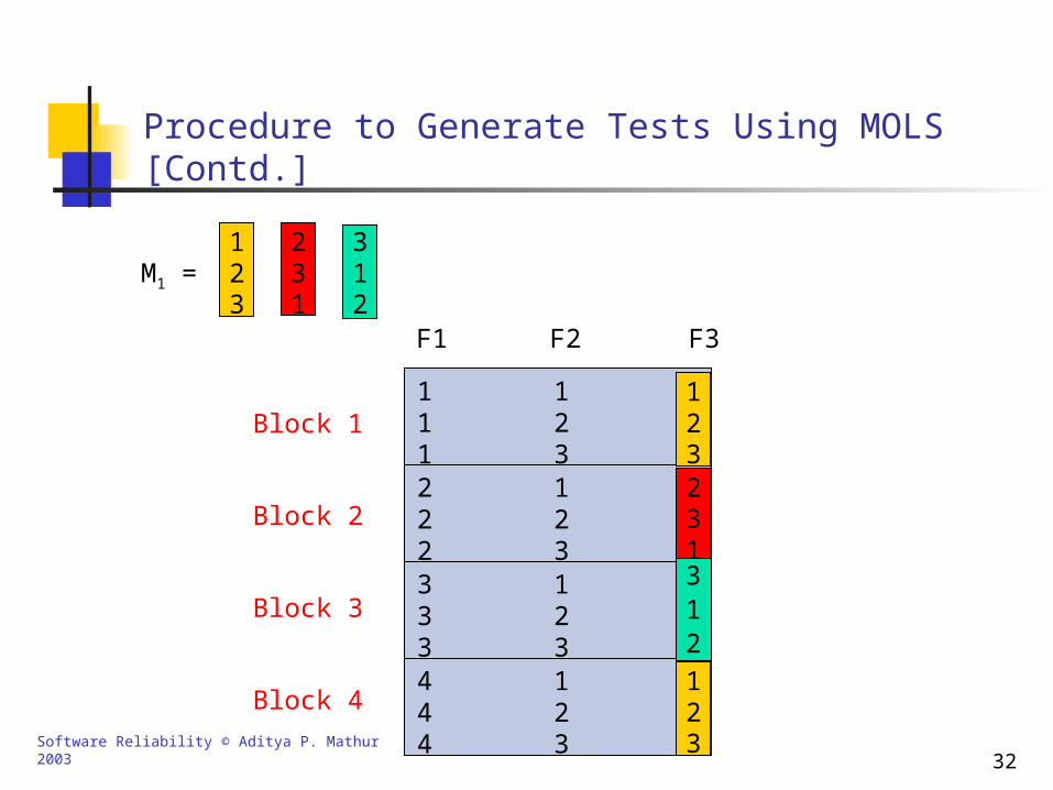
10. We have now exhausted all columns of M1. How do we fill block 4 of column F3?
Reuse columns of M1 starting with column 1.
Software Reliability © Aditya P. Mathur 2003 32
F1 F2 F3
4
44
111222333
Block 1
Block 2
Block 3
Block 4
3
12
123123123
Procedure to Generate Tests Using MOLS [Contd.]
M1 =123
231
312
123231312
123
Software Reliability © Aditya P. Mathur 2003 33
Procedure to Generate Tests Using MOLS [Contd.]
Therefore we remove all instances of 3 from column F3 of our table.
11. Note that F3 corresponds to factor Z which can assume only one of two values.

Software Reliability © Aditya P. Mathur 2003 34
F1 F2 F3
4
44
111222333
Block 1
Block 2
Block 3
Block 4
3
12
123123123
Procedure to Generate Tests Using MOLS [Contd.]
M1 =123
231
312
12
2
1
12
12
Y X Z
Software Reliability © Aditya P. Mathur 2003 35
Procedure to Generate Tests Using MOLS [Contd.]
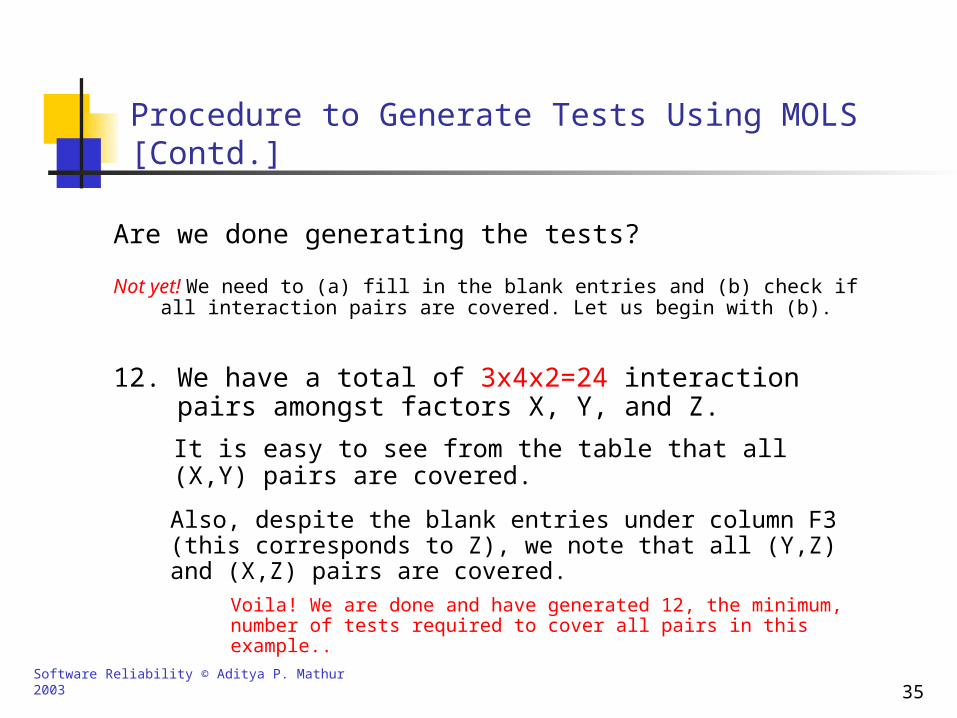
Not yet! We need to (a) fill in the blank entries and (b) check if all interaction pairs are covered. Let us begin with (b).
Are we done generating the tests?
12. We have a total of 3x4x2=24 interaction pairs amongst factors X, Y, and Z.
It is easy to see from the table that all (X,Y) pairs are covered.
Also, despite the blank entries under column F3 (this corresponds to Z), we note that all (Y,Z) and (X,Z) pairs are covered.
Voila! We are done and have generated 12, the minimum, number of tests required to cover all pairs in this example..
Software Reliability © Aditya P. Mathur 2003 36
Procedure to Generate Tests Using MOLS [Contd.]
F1 F2 F3
4
44
111222333
Block 1
Block 2
Block 3
Block 4
3
12
123123123
12
2
1
12
12
Y X Z
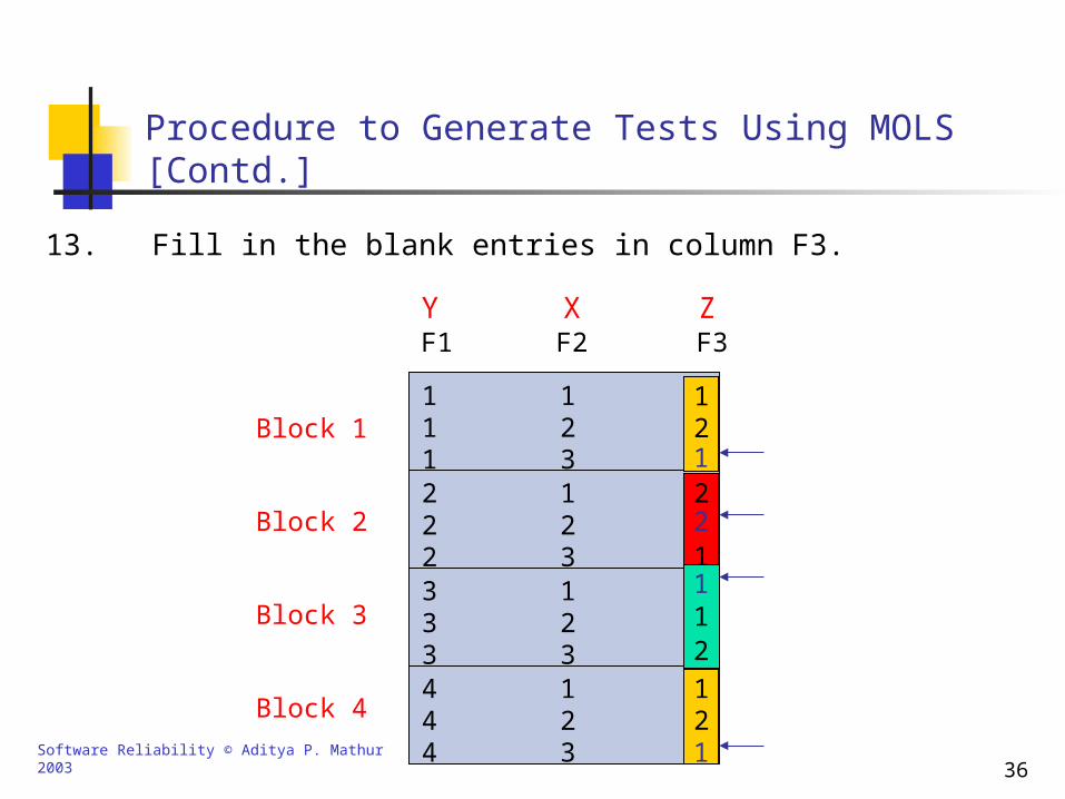
13. Fill in the blank entries in column F3.
1
2
1
1
Software Reliability © Aditya P. Mathur 2003 37
Procedure to Generate Tests Using MOLS [Contd.]
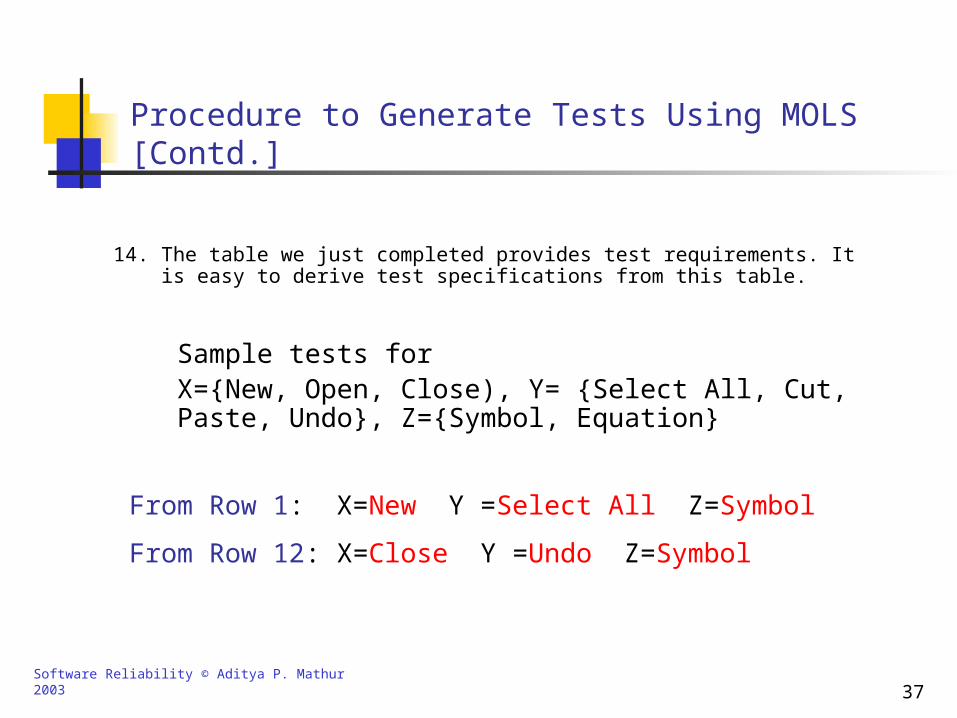
14. The table we just completed provides test requirements. It is easy to derive test specifications from this table.
Sample tests for X={New, Open, Close), Y= {Select All, Cut, Paste, Undo}, Z={Symbol, Equation}
From Row 1: X=New Y =Select All Z=Symbol
From Row 12: X=Close Y =Undo Z=Symbol
Software Reliability © Aditya P. Mathur 2003 38
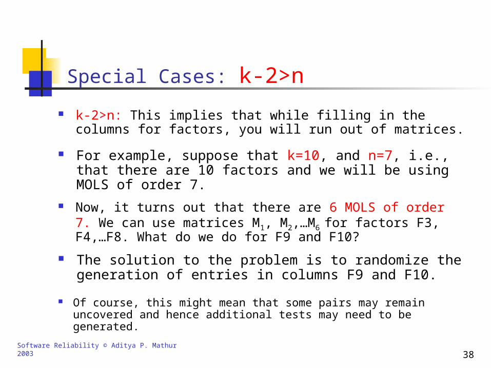
Special Cases: k-2>n
k-2>n: This implies that while filling in the columns for factors, you will run out of matrices.
For example, suppose that k=10, and n=7, i.e., that there are 10 factors and we will be using MOLS of order 7.
Now, it turns out that there are 6 MOLS of order 7. We can use matrices M1, M2,…M6 for factors F3, F4,…F8. What do we do for F9 and F10?
The solution to the problem is to randomize the generation of entries in columns F9 and F10.
Of course, this might mean that some pairs may remain uncovered and hence additional tests may need to be generated.
Software Reliability © Aditya P. Mathur 2003 39
Special Cases: |Fi|<n
|Fi|<n, i>2: This implies that factor Fi has a cardinality less than the order of the MOLS we are using. F3 in our earlier example is one such factor.
As illustrated earlier, this will lead to blank entries. These are known as “don’t care” entries and can be filled appropriately.
Software Reliability © Aditya P. Mathur 2003 40
Special Cases: MOLS of order n do not exist
This is true for n=2 and 6.
Think of the advantages and disadvantages of this approach.
In this case we are out of luck! However, one could always use MOLS of the next higher degree. This will lead to many don’t care entries that can be handled as described earlier.
Software Reliability © Aditya P. Mathur 2003 41
Special Cases: n<|F1|
When the order of MOLS is less than the cardinality of |F1|, we run out of matrix columns to use.
In this case we reuse the matrix columns.

Software Reliability © Aditya P. Mathur 2003 42
Experiments with three algorithms
Lee White conducted experiments to answer the above question.
Recall the three algorithms for generating GUI tests: GUITest, Random, and MOLS test. Which of these is the best?
Results follow..
Software Reliability © Aditya P. Mathur 2003 43
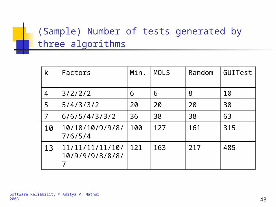
(Sample) Number of tests generated by three algorithms
k Factors Min. MOLS Random GUITest
4 3/2/2/2 6 6 8 10
5 5/4/3/3/2 20 20 20 30
7 6/6/5/4/3/3/2 36 38 38 63
10 10/10/10/9/9/8/7/6/5/4
100 127 161 315
13 11/11/11/11/10/10/9/9/9/8/8/8/7
121 163 217 485
Software Reliability © Aditya P. Mathur 2003 44
Conclusions from the Experiments
GUITest and Random perform comparably for small k but become worse as k increases.
MOLS achieves lower bound in most cases. Not in n=6 and 10 and when the randomization is to be done.
In all cases, MOLS performed better than Random and GUITest, and Random performed better than GUITest.
Software Reliability © Aditya P. Mathur 2003 45
Implications for GUI Maintenance: Addition of a Screen
The incremental changes to a GUI must be tested.
Development of GUIs is often incremental; screens are often developed one or a few at a time and full functionality of all GUI objects may not be provided..
How does the addition of a screen, or any change in the GUI, affect the set of tests already developed?
If the screen transitions depend only on the current screen, and not on the entire history, then the addition of a screen will mean the addition of GUI events to corresponding test sequences and not to all tests sequences.
Software Reliability © Aditya P. Mathur 2003 46
GUI Object Modification or Screen Deletion
In general, any screen transitions could be affected by a change and must be checked.
Similar effect on test sequences could occur when a GUI object is modified or a screen is deleted.
What is the effect on a given test sequence of adding a new GUI object?
Note that a new object corresponds to a new factor.
Software Reliability © Aditya P. Mathur 2003 47
Addition of a GUI Object
The remaining columns would not be affected unless the cardinality of the new factor is greater than that of F1 or F2.
If there exists an unused MOLS matrix then the test table can be easily modified by adding a column in the proper location corresponding to the new factor.
In this latter case the number of tests would increase and the entire table regenerated.
What is the effect on a given test sequence of deleting a GUI object, ie., deleting a factor?
Software Reliability © Aditya P. Mathur 2003 48
Deletion of a GUI Object
There will be no change in the number of tests if the factor deleted is not F1 or F2.
What is the effect on a given test sequence of adding a GUI screen that has new GUI objects?
What is the effect on a given test sequence of deleting a GUI screen and thereby deleting some GUI objects??
Software Reliability © Aditya P. Mathur 2003 49
Stability of Tests
If the GUI is modified slightly then MOLS is the most stable algorithm as long as there are more MOLS matrices available.
What is the impact on the test sequence of small changes in the GUI?
The Random algorithm is less stable but allows the reuse of previous tests.
The GUITest algorithm is the least stable and requires many more tests to be added.
Which of the three approaches would you recommend when the GUI is unpredictable both during design and maintenance?
Software Reliability © Aditya P. Mathur 2003 50
Using Don’t Care Entries: Prioritized List
Use these entries to test for additional interactions between modified GUI objects.
How best to use the don’t care entries generated when using the MOLS approach?
Use these entries to test for modified GUI elements and closely related GUI objects or screens; for example other unmodified GUI objects within the same screen, or within screens that immediately precede or follow a modified screen.
Use these entries to test for interactions between modified GUI objects and other arbitrary GUI objects in the test sequence.
Software Reliability © Aditya P. Mathur 2003 51
Using Don’t Care Entries: More Ideas!
Identify screens and GUI objects where failures contribute to a higher overall risk to the successful operation of the system.
Use these entries to test for interactions between higher and lower risk elements of the GUI.
Use these elements to utilize criteria such as boundary value testing.
Software Reliability © Aditya P. Mathur 2003 52
Questions
Are the tests generated using MOLS feasible?
How would you treat sub-menus?
How would you detect and handle infeasible tests?
Is pair wise testing sufficient?

Software Reliability © Aditya P. Mathur 2003 53
GUI Testing Using Responsibilities
A responsibility is an end-effect that the user of a GUI wants to achieve. We assume that the end-effect is observable in the surrounding environment that includes memory, peripheral device, application software, etc.
Open a file. Examples:
Copy a section of a file and paste it at another place within the same file.
Select a sequence of vertically placed objects, align them at their left edges, and evenly distribute them vertically.
Establish communication with a pacemaker, and download data recorded in its internal memory during the past 24 hours.
Software Reliability © Aditya P. Mathur 2003 54
Complete Interaction Sequences (CIS)
A CIS is sequence of objects and selections made by a user to produce a desired response (or to fulfill a desired responsibility).
[Show examples from Powerpoint.]
Examples:
A CIS might overlap with another, or be fully contained, or simply share GUI objects..
Software Reliability © Aditya P. Mathur 2003 55
Identification of Responsibilities and CISs
Responsibilities are identified using all available sources that include design documents.
A CIS is defined for each responsibility.
A finite state machine is constructed for each CIS.
Several transformations are applied to each FSM to reduce its complexity and thus tackle the state explosion problem. These transformations abstract two types of components:
Each reduced FSM is used to generate tests for the corresponding CIS.
Strongly connected component Structural symmetry component
Software Reliability © Aditya P. Mathur 2003 56
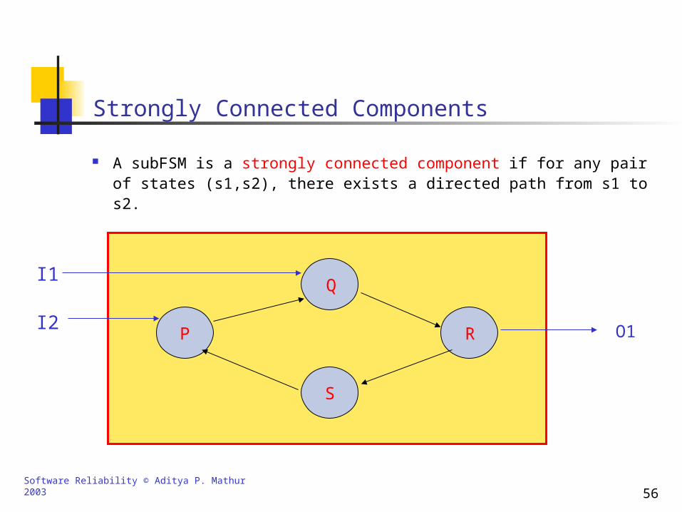
Strongly Connected Components
A subFSM is a strongly connected component if for any pair of states (s1,s2), there exists a directed path from s1 to s2.
P
Q
R
S
I1
I2 O1
Software Reliability © Aditya P. Mathur 2003 57
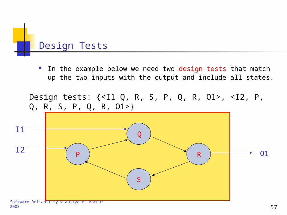
Design Tests
In the example below we need two design tests that match up the two inputs with the output and include all states.
P
Q
R
S
I1
I2 O1
Design tests: {<I1 Q, R, S, P, Q, R, O1>, <I2, P, Q, R, S, P, Q, R, O1>}
Software Reliability © Aditya P. Mathur 2003 58
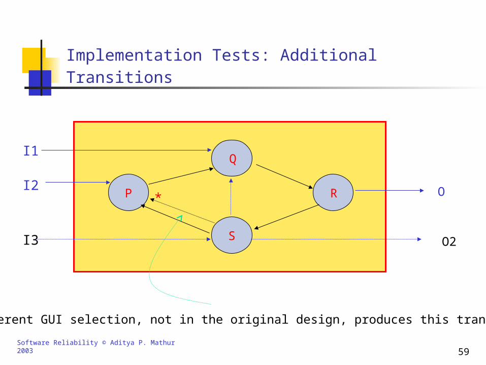
Implementation Tests
Implementation tests include all transitions that do not occur in the design but do occur in the implementation.
To obtain implementation tests determine all unused selections of each GUI object in the component under consideration.
If these selections correspond to transitions outside of this component to other states of the CIS, then they produce new outputs of the component.
Similarly, new inputs to a component are obtained by considering possible transitions to the states of a component.
Software Reliability © Aditya P. Mathur 2003 59
Implementation Tests: Additional Transitions
P
Q
R
S
I1
I2 O
I3 O2
A different GUI selection, not in the original design, produces this transition.
*
Software Reliability © Aditya P. Mathur 2003 60
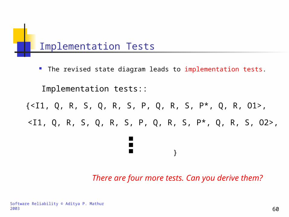
Implementation Tests
The revised state diagram leads to implementation tests.
Implementation tests::
{<I1, Q, R, S, Q, R, S, P, Q, R, S, P*, Q, R, O1>,
<I1, Q, R, S, Q, R, S, P, Q, R, S, P*, Q, R, S, O2>,
There are four more tests. Can you derive them?
}
Software Reliability © Aditya P. Mathur 2003 61
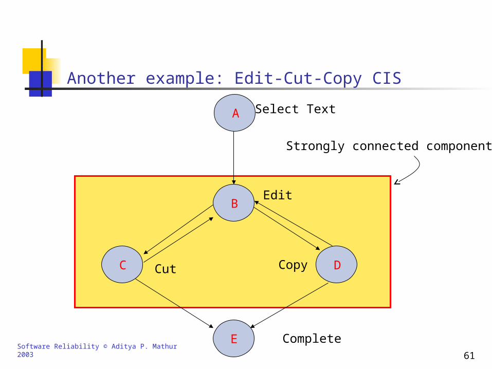
Strongly connected component
Another example: Edit-Cut-Copy CIS
A Select Text
E Complete
DCopyC Cut
BEdit
Software Reliability © Aditya P. Mathur 2003 62
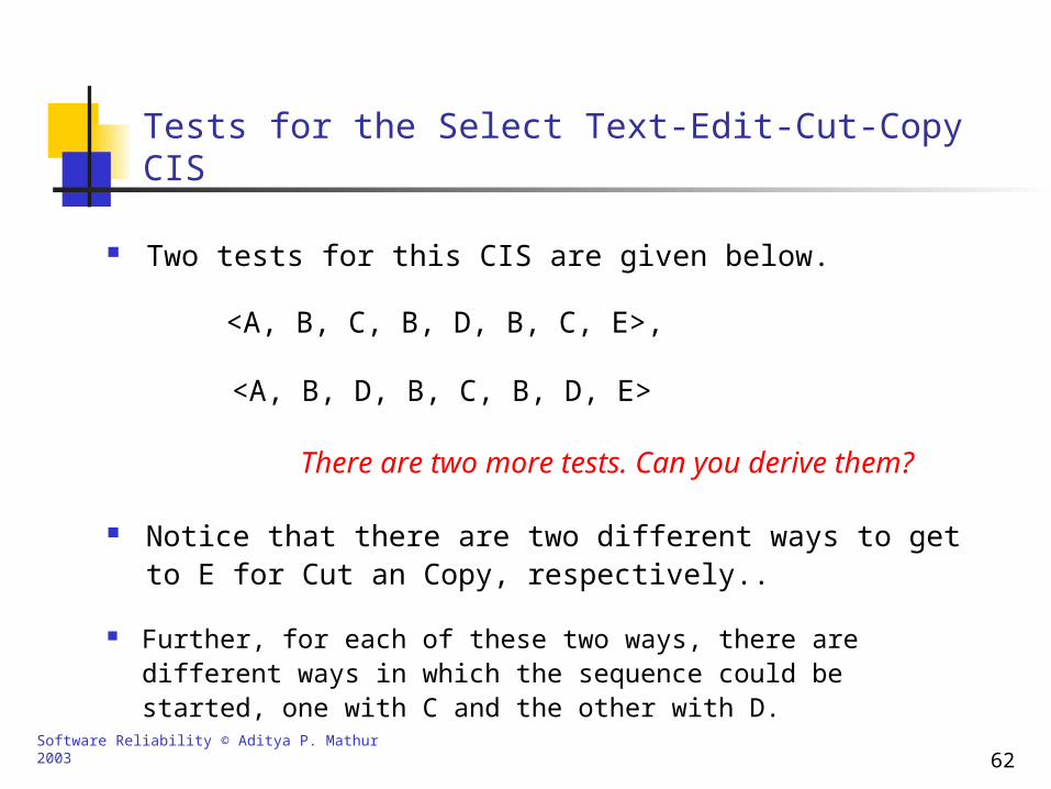
Tests for the Select Text-Edit-Cut-Copy CIS
Two tests for this CIS are given below.
<A, B, C, B, D, B, C, E>,
There are two more tests. Can you derive them?
<A, B, D, B, C, B, D, E>
Notice that there are two different ways to get to E for Cut an Copy, respectively..
Further, for each of these two ways, there are different ways in which the sequence could be started, one with C and the other with D.
Software Reliability © Aditya P. Mathur 2003 63
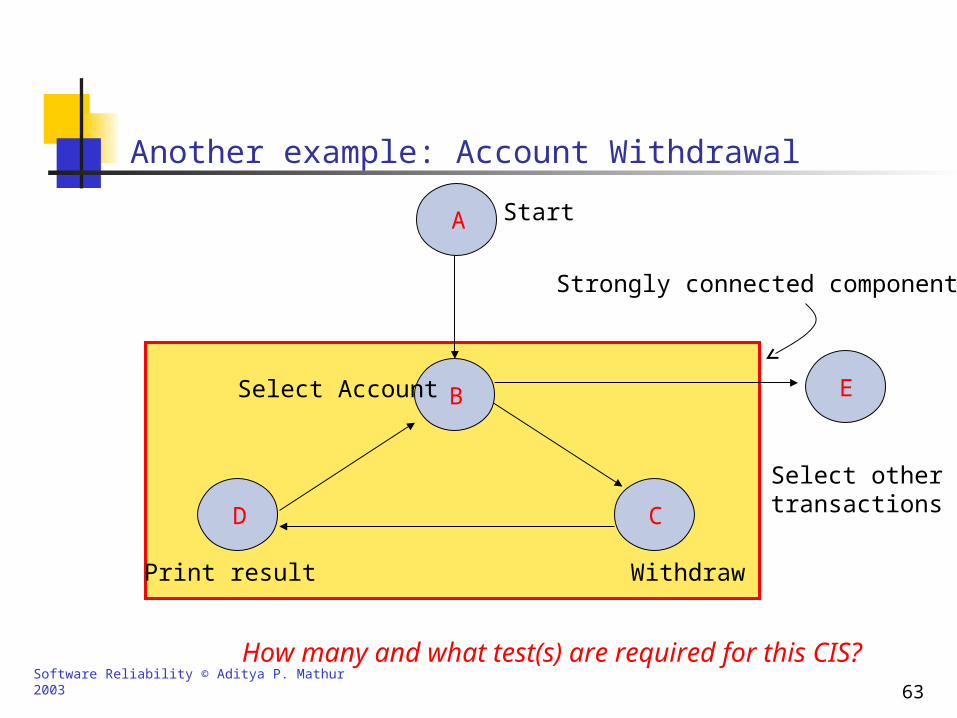
Strongly connected component
Another example: Account Withdrawal
A Start
E
Select othertransactionsC
Withdraw
D
Print result
BSelect Account
How many and what test(s) are required for this CIS?
Software Reliability © Aditya P. Mathur 2003 64
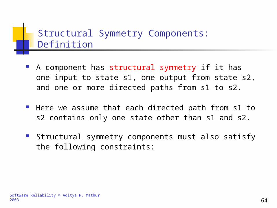
Structural Symmetry Components: Definition
A component has structural symmetry if it has one input to state s1, one output from state s2, and one or more directed paths from s1 to s2.
Here we assume that each directed path from s1 to s2 contains only one state other than s1 and s2.
Structural symmetry components must also satisfy the following constraints:
Software Reliability © Aditya P. Mathur 2003 65
Structural Symmetry Components: Constraints
The path followed to get to the input of the component has no effect on the internal paths and states of the component.
Any path traversed following the output of the component is independent of the path that was traversed within the component.
Software Reliability © Aditya P. Mathur 2003 66
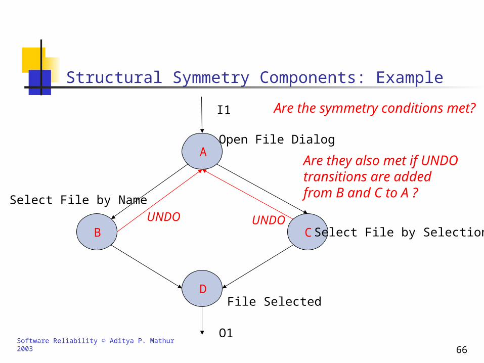
Structural Symmetry Components: Example
I1
AOpen File Dialog
C Select File by SelectionB
Select File by Name
D
O1
File Selected
Are the symmetry conditions met?
UNDO
Are they also met if UNDO transitions are addedfrom B and C to A ?
UNDO
Software Reliability © Aditya P. Mathur 2003 67
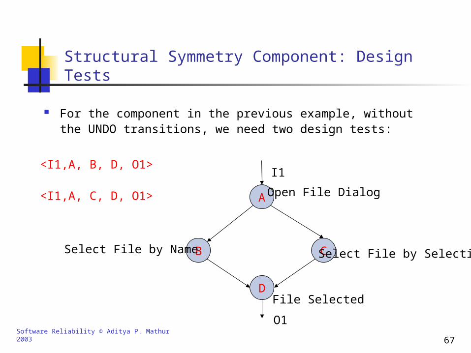
Structural Symmetry Component: Design Tests
<I1,A, B, D, O1>
<I1,A, C, D, O1>
For the component in the previous example, without the UNDO transitions, we need two design tests:
I1
A Open File Dialog
C Select File by SelectionBSelect File by Name
D
O1
File Selected
Software Reliability © Aditya P. Mathur 2003 68
Destruction of Structural Symmetry Component
For implementation testing we need to discover additional transitions.
The additional transitions will likely destroy the structural symmetry This will lead to an increase in the number of implementation tests.
However, the discovery and abstraction of components reduces the number of tests required to test a CIS FSM. Why?
This is because when testing the CIS FSM, we select only one of the several paths in each test of the FSM. Of course, we make sure that each path of the abstracted component is tested at least once.
Software Reliability © Aditya P. Mathur 2003 69
Testing the Reduced FSM: Design Tests
Each abstracted component in the CIS FSM is replaced by a superstate.
To conduct a design test, construct a sufficient test set as follows:
Each test case must correspond to a sequence of GUI actions that begin at the start node and ends at the terminating node.
The test set must cover all paths in the reduced FSM. each time a superstate is entered, an appropriate path of the corresponding component is selected.
All design tests for each abstracted component must be exercised in the complete test of the FSM.
Software Reliability © Aditya P. Mathur 2003 70
Testing the Reduced FSM: Implementation Tests
The reduced FSM for the implementation tests is likely to be larger in the its number of states than the one used in design test..
Some abstracted components might be invalidated and therefore replaced by their “complete” versions.
A sufficient set of implementation test cases must:
(b) include all the implementation tests for each abstracted component at least once.
(a) cause all paths in the modified FSM to be executed and
Software Reliability © Aditya P. Mathur 2003 71
Other Considerations
The FSM does not model the effects of the GUI and therefore the result of traversing each path must be examined carefully.
A cycle may need to be traversed different number of times at different points along a path.
All distinct paths must be generated from the start to the terminating state. However, we can exclude any path where a cycle is traversed more than once.
Note that this method is more exhaustive than simply covering each state and each transition once. Why?
Software Reliability © Aditya P. Mathur 2003 72
Example
This example shows how a CIS FSM can be reduced and tests derived from the reduced FSM.
The CIS considered is an Edit-Cut-paste-Copy-Paste sequence that involves opening two files.
We begin by developing the FSM for the given CIS.
Next, we identify the strongly connected and structural symmetry components.
All such components are replaced by a superstate.
We can now develop tests for the reduced FSM.
Software Reliability © Aditya P. Mathur 2003 73
C2
C1
C3
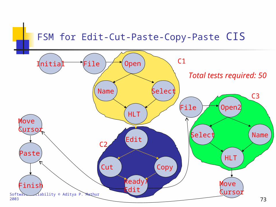
FSM for Edit-Cut-Paste-Copy-Paste CIS
Initial
Paste
Finish MoveCursor
File
Name
HLT
Select
Open
Cut
Ready/Edit
Copy
MoveCursor
Open2
Select Name
HLT
File
Edit
Total tests required: 50
Software Reliability © Aditya P. Mathur 2003 74
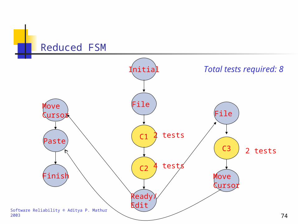
Reduced FSM
Initial
MoveCursor File
Paste
Finish MoveCursor
File
C1
Ready/Edit
C2
C3
2 tests
4 tests
2 tests
Total tests required: 8
Software Reliability © Aditya P. Mathur 2003 75
Evaluation of the CIS-based Technique
The GUIs of two applications, A and B, were subjected to CIS based testing technique.
The primary objectives of the experiment were to determine (a) how good is the technique in detecting defects in GUI implementation and (b) the reduction in the number tests achieved through the reduction of the FSM.
Defect: Serious departure from the specified behavior.
Surprise: User recognized departure from expected behavior.
Software Reliability © Aditya P. Mathur 2003 76
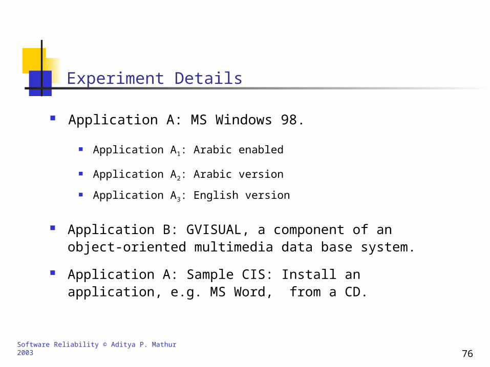
Experiment Details
Application A: MS Windows 98.
Application A1: Arabic enabled
Application A2: Arabic version
Application A3: English version
Application B: GVISUAL, a component of an object-oriented multimedia data base system.
Application A: Sample CIS: Install an application, e.g. MS Word, from a CD.
Software Reliability © Aditya P. Mathur 2003 77
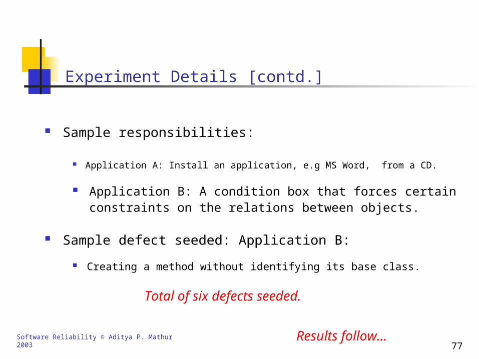
Experiment Details [contd.]
Results follow…
Sample responsibilities:
Application A: Install an application, e.g MS Word, from a CD.
Application B: A condition box that forces certain constraints on the relations between objects.
Sample defect seeded: Application B:
Creating a method without identifying its base class.
Total of six defects seeded.
Software Reliability © Aditya P. Mathur 2003 78
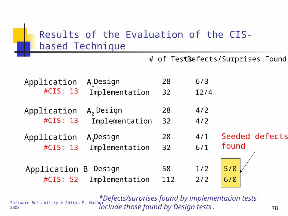
Results of the Evaluation of the CIS-based Technique# of Tests *Defects/Surprises Found
28
32
28
32
28
32
58
112
6/3
12/4
4/2
4/2
4/1
6/1
1/2
2/2
Application A1Design
Implementation#CIS: 13
Application A2Design
Implementation#CIS: 13
Application A3Design
Implementation#CIS: 13
Application B Design
Implementation#CIS: 52
5/0
6/0
Seeded defectsfound
*Defects/surprises found by implementation tests include those found by Design tests.
Software Reliability © Aditya P. Mathur 2003 79
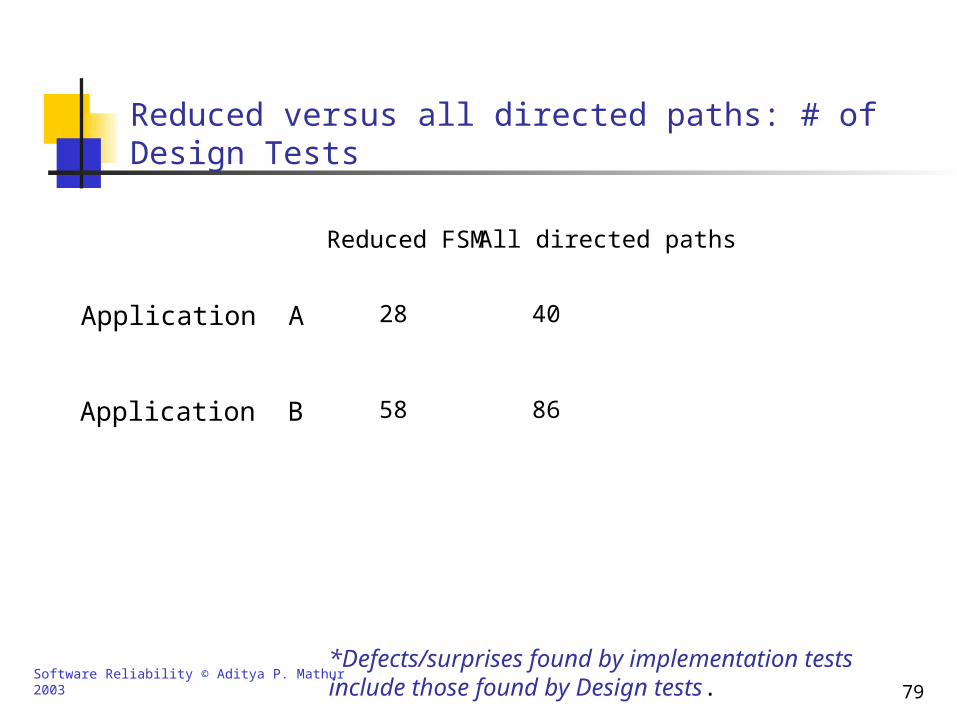
Reduced versus all directed paths: # of Design Tests
Reduced FSM All directed paths
28
58
40
86
Application A
Application B
*Defects/surprises found by implementation tests include those found by Design tests.
Software Reliability © Aditya P. Mathur 2003 80
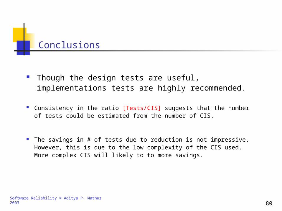
Conclusions
Though the design tests are useful, implementations tests are highly recommended.
The savings in # of tests due to reduction is not impressive. However, this is due to the low complexity of the CIS used. More complex CIS will likely to to more savings.
Consistency in the ratio [Tests/CIS] suggests that the number of tests could be estimated from the number of CIS.

![Chapter [4] Created By Manish Mathur. Testing : Definition Testing is the process of assessing Correctness, Completeness and Quality of system. Testing](https://img.pdfslide.us/doc/110x75/5517ade45503463e368b5e8a/chapter-4-created-by-manish-mathur-testing-definition-testing-is-the-process-of-assessing-correctness-completeness-and-quality-of-system-testing.jpg)