Embed Size (px)
DESCRIPTION
Software Requirements. Specifying system functionality and constraints Chapters 5 and 6 ++. Requirements engineering. Requirements engineering (or requirements analysis) is the process of establishing: the services that the customer requires from a system - PowerPoint PPT Presentation
Citation preview

1
Software Requirements
Specifying system functionality and constraints
Chapters 5 and 6 ++

2
Requirements engineering Requirements engineering (or requirements analysis)
is the process of establishing:• the services that the customer requires from a system• the constraints under which it operates and is developed
A requirement may range from a high-level abstract statement of a service or constraint to a detailed mathematical expression
Failure here is a major cause of software development failures.
3
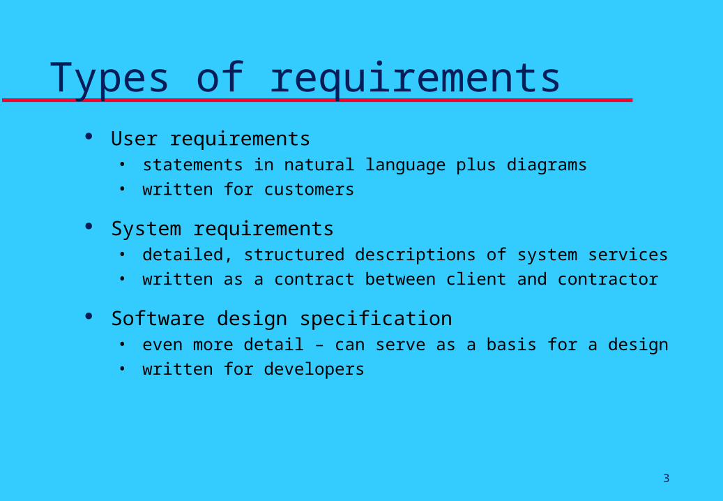
Types of requirements User requirements
• statements in natural language plus diagrams• written for customers
System requirements• detailed, structured descriptions of system services• written as a contract between client and contractor
Software design specification• even more detail – can serve as a basis for a design• written for developers

4
Requirement classification
Functional requirements• statements of services the system should provide• they describe how the system should react to particular
inputs and how it should behave in particular situations• might include user interface issues
Constraints• constraints on the services offered by the system• timing constraints, standards, development processes

5
Functional requirements examples The user shall be able to search either all of the initial set of
databases or select a subset from that set to search.
The system shall provide the viewers listed in Appendix B: Supported Viewer Software, for the user to read documents in the document store.
Every order shall be allocated a unique identifier which the user shall be able to copy to the account’s permanent storage area.

6
Process activities Domain understanding
Requirements discovery or elicitation
Analysis and conflict resolution
Classification, Prioritization
Specification
Verification

7
Requirements Discovery Involves technical staff working with customers to
find out about the application domain, the services that the system should provide and the system’s operational constraints
May involve various stakeholders: end-users, managers, engineers involved in maintenance, domain experts, trade unions, etc.

8
Why is it difficult? Client doesn’t know what they really want
Client underestimates importance
Client makes assumptions
Producer not familiar with application area
Different stakeholders may have conflicting requirements
Difficult client/producer chemistry
The requirements change during the analysis process

9
Be wary of runaway requirements Do not allow scope creep
Be aware of “kitchen sink” user approach
Elicit justification of requirements
Reject if not plausible or cost/benefit high

10
Methods of Discovery
Should use a well-defined methodical approach:
Introspection
Elicitation• Interviews
• Observation (Ethnography)
• Protocol Analysis
Viewpoint Oriented
Prototypes

11
The requirements document The requirements document is the official statement of
what is required of the system developers
It is read by a variety of stakeholders (people interested in the system and its development)
It is not a design document
As much as possible, it should specify what the system should do rather than how it should do it

12
IEEE requirements standard Defines a generic structure for a requirements
specification:• Introduction
• Purpose, Scope, Definitions, References, Overview
• General description• Perspective, Functions, User, Constraints
• Specific requirements
• Appendices
• Index

13
Specific Requirements (IEEE) Include functional, interface, performance, design
constraints, quality attributes, etc.
Each functional should include• overview
• inputs
• processing
• outputs
• exceptions

14
Alternatives to natural language Structured natural language
• standard templates
Program design language (PDL)• like a programming language, but more abstract
Graphical notation• diagrams with text annotations
Mathematical specification• formal and precise (ex: finite state machine)

15
Form-based specificationECLIPSE/Workstation/Tools/DE/FS/3.5.1
Function Add node
Description Adds a node to an existing design. The user selects the type of node, and its position.When added to the design, the node becomes the current selection. The user chooses the node position bymoving the cursor to the area where the node is added.
Inputs Node type, Node position, Design identifier.
Source Node type and Node position are input by the user, Design identifier from the database.
Outputs Design identifier.
Destination The design database. The design is committed to the database on completion of theoperation.
Requires Design graph rooted at input design identifier.
Pre-condition The design is open and displayed on the user's screen.
Post-condition The design is unchanged apart from the addition of a node of the specified typeat the given position.
Side-effects None
Definition: ECLIPSE/Workstation/Tools/DE/RD/3.5.1
16
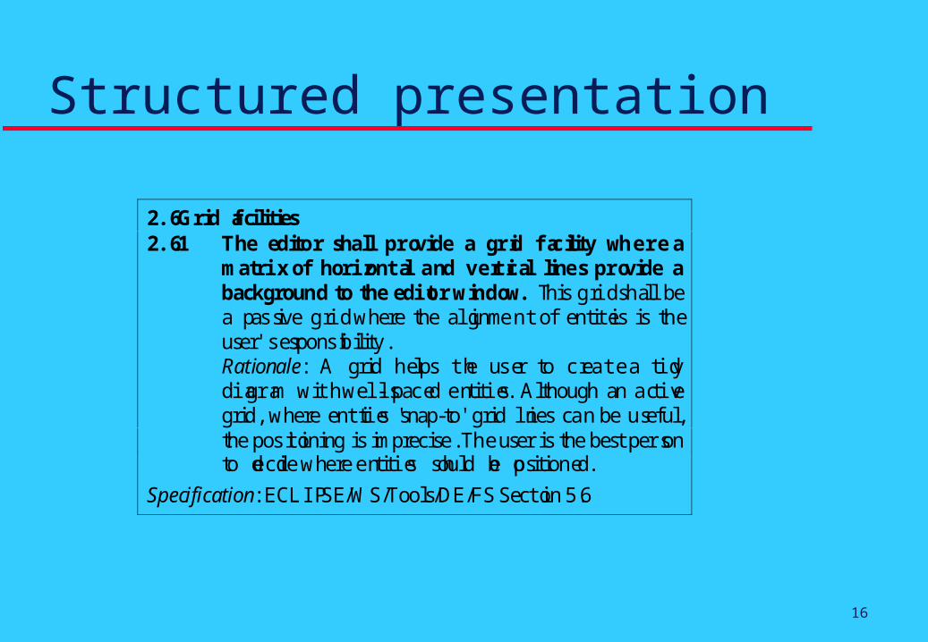
Structured presentation
2.6 Grid facilities2.6.1 The editor shall provide a grid facility where a
matrix of horizontal and vertical lines provide abackground to the editor window. T his grid shall bea p assive grid where the alignment of entities is theuser's responsibility.Rationale: A grid helps the user to create a tidydiagram with well-spaced entities. Although an activegrid, where entities 'snap-to' grid lines can be useful,the positioning is imprecise. The user is the best personto decide where entities should be positioned.
Specification: ECLIPSE/WS/Tools/DE/FS Section 5.6

17
The VORD process model Viewpoint identification
Viewpoint structuring
Viewpoint documentation
Viewpoint-system mapping

18
Scenarios Scenarios are descriptions of how a system is used in
practice
They are helpful in requirements elicitation as people can relate to these more readily than abstract statement of what they require from a system
Scenarios can be included in a user oriented requirements document.

19
Scenario descriptions The description of a scenario includes:
• System state at the beginning of the scenario
• Normal flow of events in the scenario
• What can go wrong and how this is handled
• Other concurrent activities
• System state on completion of the scenario

20
Use cases Use cases are a scenario-based technique in UML
which identify the actors in an interaction and which describe the interaction itself
A set of use cases should describe all possible interactions with the system
Sequence diagrams may be used to add detail to use cases by showing the sequence of event processing in the system

21
Catalog management
Bookshop:Supplier
Cataloguer:Library Staff
Item:Library Item
Books:Catalog
Acquire New
Catalog Item
Uncatalog Item
Dispose

22
Desirable Properties of the SRSand of requirements themselves
Usable
Complete and Consistent
Well structured
Traceable and Verifiable
Annotated in appropriate ways
Good technical writing used
23
Usable Correct!
Understandable
Achievable
Design Independent
At Right Level of Detail

24
Complete and Consistent
In principle requirements should be both complete and consistent
Complete – they should include descriptions of all facilities required
Consistent – there should be no conflicts or contradictions in the descriptions
In practice, for large systems, it is almost impossible to produce a complete and consistent requirements document

25
Well Structured Standard organization
Modifiable• Layout
• Limit Redundancy
Indexed (automated?)

26
Traceable
Traceability is concerned with the relationships between requirements, their sources and the design
Source traceability• Links from requirements to stakeholders who proposed these
requirements
Requirements traceability• Links between dependent requirements
Design traceability• Design Document can reference the requirements separately

27
Verifiable Goals can be fuzzy. Requirements should not be. There should
exist a finite, cost-effective way to check each one. A system goal
• The system should be easy to use by experienced controllers and should be organized in such a way that user errors are minimized.
A verifiable non-functional requirement• Experienced controllers shall be able to use all the system functions
after a total of two hours training. After this training, the average number of errors made shall not exceed two per day.
Defining verifiable requirements can be difficult.

28
Requirements measuresProperty MeasureSpeed Processed transactions/second
User/Event response timeScreen refresh time
Size K BytesNumber of RAM chips
Ease of use Training timeNumber of help frames
Reliability Mean time to failureProbability of unavailabilityRate of failure occurrenceAvailability
Robustness Time to restart after failurePercentage of events causing failureProbability of data corruption on failure
Portability Percentage of target dependent statementsNumber of target systems

29
Annotated Appropriately by relative importance
• must, should, could
by relative stability
by version

30
Use Good Technical Writing Unambiguous
Concise
and so on …..


![Software Requirements - The Process Groupprocessgroup.com/software-requirements-v10-full.pdf · What is a Software Requirement? ... [Based on K. Wiegers Software Requirements]](https://img.pdfslide.us/doc/110x75/5b7ba4ad7f8b9ab87f8e69be/software-requirements-the-process-what-is-a-software-requirement-based.jpg)