Embed Size (px)
Citation preview

© Copyright 1993, 1995 National Instruments Corporation.All Rights Reserved.
NI-488.2M™
Software Reference Manualfor OS/2
January 1995 Edition
Part Number 370950A-01

National Instruments Corporate Headquarters6504 Bridge Point ParkwayAustin, TX 78730-5039(512) 794-0100Technical support fax: (800) 328-2203
(512) 794-5678
Branch Offices:Australia (03) 879 9422, Austria (0662) 435986, Belgium 02/757.00.20,Canada (Ontario) (519) 622-9310, Canada (Québec) (514) 694-8521,Denmark 45 76 26 00, Finland (90) 527 2321, France (1) 48 14 24 24,Germany 089/741 31 30, Italy 02/48301892, Japan (03) 3788-1921,Mexico 95 800 010 0793, Netherlands 03480-33466, Norway 32-84 84 00,Singapore 2265886, Spain (91) 640 0085, Sweden 08-730 49 70,Switzerland 056/20 51 51, Taiwan 02 377 1200, U.K. 0635 523545

Limited Warranty
The media on which you receive National Instruments software arewarranted not to fail to execute programming instructions, due to defects inmaterials and workmanship, for a period of 90 days from date of shipment,as evidenced by receipts or other documentation. National Instruments will,at its option, repair or replace software media that do not executeprogramming instructions if National Instruments receives notice of suchdefects during the warranty period. National Instruments does not warrantthat the operation of the software shall be uninterrupted or error free.
A Return Material Authorization (RMA) number must be obtained from thefactory and clearly marked on the outside of the package before anyequipment will be accepted for warranty work. National Instruments willpay the shipping costs of returning to the owner parts which are covered bywarranty.
National Instruments believes that the information in this manual isaccurate. The document has been carefully reviewed for technical accuracy.In the event that technical or typographical errors exist, NationalInstruments reserves the right to make changes to subsequent editions ofthis document without prior notice to holders of this edition. The readershould consult National Instruments if errors are suspected. In no eventshall National Instruments be liable for any damages arising out of orrelated to this document or the information contained in it.
EXCEPT AS SPECIFIED HEREIN, NATIONAL INSTRUMENTS MAKES NOWARRANTIES, EXPRESS OR IMPLIED, AND SPECIFICALLY DISCLAIMSANY WARRANTY OF MERCHANTABILITY OR FITNESS FOR APARTICULAR PURPOSE. CUSTOMER'S RIGHT TO RECOVER DAMAGESCAUSED BY FAULT OR NEGLIGENCE ON THE PART OF NATIONALINSTRUMENTS SHALL BE LIMITED TO THE AMOUNT THERETOFOREPAID BY THE CUSTOMER. NATIONAL INSTRUMENTS WILL NOT BELIABLE FOR DAMAGES RESULTING FROM LOSS OF DATA, PROFITS,USE OF PRODUCTS, OR INCIDENTAL OR CONSEQUENTIAL DAMAGES,EVEN IF ADVISED OF THE POSSIBILITY THEREOF. This limitation of theliability of National Instruments will apply regardless of the form of action,whether in contract or tort, including negligence. Any action againstNational Instruments must be brought within one year after the cause ofaction accrues. National Instruments shall not be liable for any delay inperformance due to causes beyond its reasonable control. The warrantyprovided herein does not cover damages, defects, malfunctions, or servicefailures caused by owner's failure to follow the National Instruments

installation, operation, or maintenance instructions; owner's modification ofthe product; owner's abuse, misuse, or negligent acts; and power failure orsurges, fire, flood, accident, actions of third parties, or other events outsidereasonable control.
Copyright
Under the copyright laws, this publication may not be reproduced ortransmitted in any form, electronic or mechanical, including photocopying,recording, storing in an information retrieval system, or translating, inwhole or in part, without the prior written consent of National InstrumentsCorporation.
Trademarks
NI-488®, NI-488.2™, and NI-488.2M™ are trademarks of NationalInstruments Corporation.
Product and company names listed are trademarks or trade names of theirrespective companies.
Warning Regarding Medical and Clinical Useof National Instruments Products
National Instruments products are not designed with components and testingintended to ensure a level of reliability suitable for use in treatment anddiagnosis of humans. Applications of National Instruments productsinvolving medical or clinical treatment can create a potential for accidentalinjury caused by product failure, or by errors on the part of the user orapplication designer. Any use or application of National Instrumentsproducts for or involving medical or clinical treatment must be performed byproperly trained and qualified medical personnel, and all traditional medicalsafeguards, equipment, and procedures that are appropriate in the particularsituation to prevent serious injury or death should always continue to beused when National Instruments products are being used. NationalInstruments products are NOT intended to be a substitute for any form ofestablished process, procedure, or equipment used to monitor or safeguardhuman health and safety in medical or clinical treatment.

© National Instruments Corp. v NI-488.2M SRM for OS/2
Contents
About This Manual ..........................................................................xiOrganization of This Manual......................................................xiConventions Used in This Manual ............................................. xiiHow to Use This Manual Set......................................................xivRelated Documentation ..............................................................xvCustomer Communication ..........................................................xv
Chapter 1NI-488.2M Software Description................................................1-1
The NI-488.2M Software Package ............................................. 1-1NI-488.2M Driver and Driver Utilities ........................1-1Language Files ............................................................. 1-2Example Program Files ................................................1-2API-Related Files......................................................... 1-3
How the NI-488.2M Software Works with OS/2....................... 1-4GPIB Overview ..........................................................................1-5
The IEEE 488 Standard and GPIB............................... 1-5Talkers, Listeners, and Controllers ..............................1-5Controller-In-Charge and System Controller............... 1-6Sending Messages Across the GPIB ............................1-6
Data Lines ......................................................1-6Handshake Lines............................................1-6Interface Management Lines ......................... 1-7
Setting Up and Configuring Your System ................... 1-7Controlling More Than One Board ..............................1-9
Chapter 2Application Examples..................................................................... 2-1
Example 1: Basic Communication ............................................2-2Example 2: Clearing and Triggering Devices ........................... 2-4Example 3: Asynchronous I/O................................................... 2-6Example 4: End-of-String Mode ............................................... 2-8Example 5: Service Requests..................................................... 2-10Example 6: Basic Communication with IEEE 488.2
Compliant Devices................................................. 2-14Example 7: Serial Polls Using NI-488.2 Routines ....................2-16Example 8: Parallel Polls........................................................... 2-18Example 9: Non-Controller Example ........................................2-21

Contents
NI-488.2M SRM for OS/2 vi © National Instruments Corp.
Chapter 3Developing Your Application....................................................... 3-1
Choosing a Programming Method..............................................3-1Using the NI-488.2 Language Interface....................... 3-1
Using NI-488 Functions: One Device forEach Board..................................................... 3-2
NI-488 Device-Level Functions ......3-2NI-488 Board-Level Functions ....... 3-3
Using NI-488.2 Routines: Multiple Boardsand/or Multiple Devices................................. 3-3
Using the OS/2 API Interface....................................... 3-4Checking Status with Global Variables......................................3-4
Status Word—ibsta ......................................................3-4Error Variable—iberr ................................................... 3-6Count Variables—ibcnt and ibcntl............................... 3-6
Using ibic to Communicate with Devices ..................................3-7Writing Your NI-488 Application ..............................................3-7
Items to Include............................................................3-7NI-488 Program Shell ..................................................3-8General Program Steps and Examples ......................... 3-9
Writing Your NI-488.2 Application ........................................... 3-13Items to Include............................................................3-13NI-488.2 Program Shell ............................................... 3-14General Program Steps and Examples ......................... 3-15
Compiling and Linking Your Program....................................... 3-2032-Bit C Applications................................................... 3-2016-Bit C Applications................................................... 3-21
Running Your Application Program........................................... 3-21
Chapter 4Debugging Your Application ....................................................... 4-1
Running ibtest............................................................................. 4-1Presence Test of Driver ................................................4-1Presence Test of GPIB Board....................................... 4-2Incorrect Interrupt Level ..............................................4-2GPIB Cables Connected............................................... 4-2
Debugging with the Global Status Variables ............................. 4-3Debugging with ibic ................................................................... 4-3GPIB Error Codes....................................................................... 4-3Configuration Errors................................................................... 4-4
Reconfiguring the NI-488.2M Software ......................4-5Timing Errors ............................................................................. 4-5

Contents
© National Instruments Corp. vii NI-488.2M SRM for OS/2
Communication Errors ............................................................... 4-6Repeat Addressing ....................................................... 4-6Termination Method..................................................... 4-6
Chapter 5ibic—Interface Bus Interactive Control Utility ....................5-1
Overview..................................................................................... 5-1Starting ibic................................................................................. 5-1Exiting ibic ................................................................................. 5-2ibic Syntax ..................................................................................5-2Adding End-of-String Characters............................................... 5-9Status Word Return..................................................................... 5-9Error Codes Return..................................................................... 5-10Count Return............................................................................... 5-10Common NI-488.2 Routines in ibic ........................................... 5-11
Send..............................................................................5-11Receive......................................................................... 5-12
Common NI-488 Functions in ibic............................................. 5-13ibfind ............................................................................5-13ibdev............................................................................. 5-13ibwrt ............................................................................. 5-16ibrd ............................................................................... 5-17
Auxiliary Functions ....................................................................5-18Set (Select Device or Board)........................................5-19Help (Display Help Information) ................................. 5-20! (Repeat Previous Function) ....................................... 5-21- (Turn OFF Display) and + (Turn ON Display) ......... 5-21n* (Repeat Function n Times)......................................5-22$ (Execute Indirect File)............................................... 5-23Print (Display the ASCII String)..................................5-24
ibic Examples ............................................................................. 5-24NI-488.2 Routines Example......................................... 5-24NI-488 Device Functions Example ..............................5-28NI-488 Board Functions Example ............................... 5-31
Chapter 6GPIB Programming Techniques................................................6-1
Termination of Data Transfers ................................................... 6-1Waiting for GPIB Conditions..................................................... 6-2Device-Level Calls and Bus Management ................................. 6-2Serial Polling ..............................................................................6-3
Service Requests from IEEE 488 Devices................... 6-3Service Requests from IEEE 488.2 Devices ................6-4
Contents
NI-488.2M SRM for OS/2 viii © National Instruments Corp.
Automatic Serial Polling ..............................................6-4Autopolling and the Stuck SRQ State ........... 6-5Autopolling and Interrupts............................. 6-5
SRQ and Serial Polling with NI-488 DeviceFunctions ......................................................................6-6SRQ and Serial Polling with NI-488.2 Routines ......... 6-6
Example 1 ......................................................6-7Example 2 ......................................................6-8
Parallel Polling ........................................................................... 6-9Implementing a Parallel Poll ........................................6-9
Parallel Polling with NI-488.2 Routines........6-9Parallel Polling with NI-488 Functions ......... 6-10
Chapter 7ibconf—Interface Bus Configuration Utility ......................... 7-1
Overview..................................................................................... 7-1Starting ibconf ............................................................................7-1Levels of ibconf ..........................................................................7-2
Input Selection Level ................................................... 7-2Map Level ....................................................................7-4
Device Map of the Boards ............................. 7-5Help................................................................7-5Rename ..........................................................7-5(Dis)connect................................................... 7-6Edit................................................................. 7-6Exit................................................................. 7-6
Description Level ......................................................... 7-7Change Characteristics................................... 7-8Next Board/Device......................................... 7-8Help................................................................7-8Reset Value ....................................................7-8Return to Map ................................................7-8
Output Selection Level................................................. 7-9Board and Device Configuration Options ..................................7-9
Primary GPIB Address................................................. 7-10Secondary GPIB Address............................................. 7-10Timeout Setting ............................................................7-10Terminate Read on EOS............................................... 7-11Set EOI with EOS on Write ......................................... 7-11Type of Compare on EOS ............................................7-11EOS Byte......................................................................7-11Send EOI at End of Write ............................................7-12GPIB-Specific Errors ................................................... 7-12

Contents
© National Instruments Corp. ix NI-488.2M SRM for OS/2
System Controller......................................................... 7-12Assert REN when SC................................................... 7-12Enable Auto Serial Polling........................................... 7-13Enable CIC Protocol..................................................... 7-13Bus Timing................................................................... 7-13Parallel Poll Duration................................................... 7-13Use This GPIB Interface ..............................................7-14Base I/O Address ......................................................... 7-14DMA Channel ..............................................................7-14Interrupt Jumper Setting............................................... 7-15DMA Transfer Mode ................................................... 7-15Serial Poll Timeout....................................................... 7-15Enable Repeat Addressing ........................................... 7-15
Default Configurations in ibconf ................................................7-16Exiting ibconf ............................................................................. 7-17
Appendix AStatus Word Conditions................................................................. A-1
Appendix BError Codes and Solutions............................................................B-1
Appendix CCustomer Communication............................................................C-1
Glossary................................................................................................. G-1
Index....................................................................................................... I-1

Contents
NI-488.2M SRM for OS/2 x © National Instruments Corp.
Figures
Figure 1-1. How the NI-488.2M Software Works with OS/2 ............1-4Figure 1-2. Linear and Star System Configuration............................. 1-8Figure 1-3. Example of Multiboard System Setup............................. 1-9
Figure 2-1. Program Flowchart for Example 1................................... 2-3Figure 2-2. Program Flowchart for Example 2................................... 2-5Figure 2-3. Program Flowchart for Example 3................................... 2-7Figure 2-4. Program Flowchart for Example 4................................... 2-9Figure 2-5. Program Flowchart for Example 5................................... 2-12Figure 2-6. Program Flowchart for Example 6................................... 2-15Figure 2-7. Program Flowchart for Example 7................................... 2-17Figure 2-8. Program Flowchart for Example 8................................... 2-20Figure 2-9. Program Flowchart for Example 9................................... 2-22
Figure 3-1. General Program Shell Using NI-488 DeviceFunctions..........................................................................3-8
Figure 3-2. General Program Shell Using NI-488.2 Routines ........... 3-14
Figure 7-1. Input Selection Level of ibconf ....................................... 7-2Figure 7-2. Map Level of ibconf ........................................................7-4Figure 7-3. Description Level of ibconf ............................................. 7-7Figure 7-4. Output Selection Level of ibconf..................................... 7-9
Tables
Table 1-1. GPIB Handshake Lines....................................................1-6Table 1-2. GPIB Interface Management Lines ................................. 1-7
Table 3-1. Status Word (ibsta) Layout ..............................................3-5
Table 4-1. GPIB Error Codes............................................................4-4
Table 5-1. Syntax for NI-488 Functions in ibic ................................5-3Table 5-2. Syntax for NI-488.2 Routines in ibic............................... 5-5Table 5-3. Auxiliary Functions in ibic ..............................................5-18
Table A-1. Status Word (ibsta) Layout ..............................................A-1
Table B-1. GPIB Error Codes............................................................B-1

© National Instruments Corp. xi NI-488.2M SRM for OS/2
About This Manual
This manual describes the features and functions of the NI-488.2M software forOS/2. The NI-488.2M software package is meant to be used with OS/2 (IBMOperating System/2) version 2.0 or higher. This manual assumes that you arealready familiar with the OS/2 system.
Organization of This Manual
This manual is organized as follows:
• Chapter 1, NI-488.2M Software Description, describes the NI-488.2Msoftware package and explains how the software works with your OS/2system.
• Chapter 2, Application Examples, contains nine sample applications designedto illustrate specific GPIB concepts and techniques that can help you writeyour own applications. The description of each example includes theprogrammer’s task, a program flowchart, and numbered steps that correspondto the numbered blocks on the flowchart.
• Chapter 3, Developing Your Application, explains how to develop a GPIBapplication program using NI-488 functions and NI-488.2 routines.
• Chapter 4, Debugging Your Application, describes several ways to debugyour application program.
• Chapter 5, ibic—Interface Bus Interactive Control Utility, introduces you toibic , the interactive control program that you can use to communicatewith GPIB devices through functions you enter at your keyboard.
• Chapter 6, GPIB Programming Techniques, discusses the following GPIBtopics: data transfer termination methods, waiting for GPIB conditions,device-level calls and bus management, serial polling and SRQ servicing,and parallel polling.
• Chapter 7, ibconf—Interface Bus Configuration Utility, contains adescription of ibconf , the software configuration program you can use toconfigure the NI-488.2M software.
About This Manual
NI-488.2M SRM for OS/2 xii © National Instruments Corp.
• Appendix A, Status Word Conditions, gives a detailed description of theconditions reported in the status word, ibsta .
• Appendix B, Error Codes and Solutions, lists a description of each error,some conditions under which it might occur, and possible solutions.
• Appendix C, Customer Communication, contains forms you can use torequest help from National Instruments or to comment on our products andmanuals.
• The Glossary contains an alphabetical list and a description of terms,including abbreviations, acronyms, metric prefixes, mnemonics, andsymbols, that this manual uses.
• The Index contains an alphabetical list of key terms and topics in thismanual and it includes the page where you can find each term and topic.
Conventions Used in This Manual
The following conventions are used in this manual.
italic Italic text denotes emphasis, cross references, fieldnames, or an introduction to a key concept.
bold italic Bold italic text denotes a note, caution, or warning.
monospace Text in this font denotes text or characters that youenter from the keyboard. Sections of code,programming examples, and syntax examples alsoappear in this font. This font is also used for theproper name of disk drives, paths, directories, devicenames, variables, and for statements taken fromprogram code.
bold monospace Bold text in this font denotes the messages and responsesthat the computer automatically prints to the screen.

About This Manual
© National Instruments Corp. xiii NI-488.2M SRM for OS/2
italic monospace Italic lowercase text in this font denotes that you mustsupply the appropriate words or values in the place ofthese items.
<> Angle brackets enclose the name of a key on thekeyboard—for example, <PageDown>.
<Enter> Key names are capitalized.
- A hyphen between two or more key names enclosedin angle brackets denotes that you shouldsimultaneously press the named keys—for example,<Control-C>.
enter Enter is reserved to mean that the commandsimmediately succeeding the word must be typed intothe computer and then executed by pressing the<Return> key on the keyboard.
IEEE 488 and IEEE 488 and IEEE 488.2 refer to theIEEE 488.2 ANSI/IEEE Standard 488.1-1987 and the
ANSI/IEEE Standard 488.2-1987, respectively,which define the GPIB.
NI-488.2M software NI-488.2M software refers to the NI-488.2M softwarefor OS/2 unless otherwise noted.
Abbreviations, acronyms, metric prefixes, mnemonics, symbols, and terms arelisted in the Glossary.

About This Manual
NI-488.2M SRM for OS/2 xiv © National Instruments Corp.
How to Use This Manual Set
NI-488.2M Software Reference Manual
for OS/2
Application Development and Examples
Getting Started Manual
Novice Users
Installation and Configuration
NI-488.2M Function Reference Manual
for OS/2
Experienced Users
Function and Routine Descriptions
Use the getting-started manual to install and configure your GPIB hardware andNI-488.2M software for OS/2.
Use the software reference manual if you want to learn the basics of GPIB andhow to develop an application program. The software reference manual alsocontains debugging information and detailed examples.
Use the function reference manual for specific information about each NI-488function and NI-488.2 routine, such as format, parameters, and possible errors.

About This Manual
© National Instruments Corp. xv NI-488.2M SRM for OS/2
Related Documentation
The following documents contain information that you may find helpful as youread this manual:
• OS/2 Technical Library, Application Design Guide
• OS/2 Technical Library, Control Program Programming Reference
• OS/2 Technical Library, Programming Guide Volume I
• OS/2 Technical Library, Programming Guide Volume II
• OS/2 Technical Library, Programming Guide Volume III
• ANSI/IEEE Standard 488.1-1987, IEEE Standard Digital Interface forProgrammable Instrumentation.
• ANSI/IEEE Standard 488.2-1987, IEEE Standard Codes, Formats, Protocols,and Common Commands.
Customer Communication
National Instruments wants to receive your comments on our products andmanuals. We are interested in the applications you develop with our products,and we want to help if you have problems with them. To make it easy for you tocontact us, this manual contains comment and configuration forms for you tocomplete. These forms are in Appendix C, Customer Communication, at the endof this manual.

© National Instruments Corp. 1-1 NI-488.2M SRM for OS/2
Chapter 1NI-488.2M Software Description
This chapter describes the NI-488.2M software package and explains how thesoftware works with your OS/2 system.
The NI-488.2M Software Package
The following section highlights important elements of the NI-488.2M softwarefor OS/2 and describes the function of each element.
NI-488.2M Driver and Driver Utilities
The distribution disk contains the following driver and utility files.
• readme.doc is a documentation file that contains important informationabout the NI-488.2M software and a description of any new features.Before you use the software, read this file for the most recent information.
• install.cmd is an OS/2 command file that performs the softwareinstallation. It does not modify your config.sys file.
• gpib.sys is the software driver file that is loaded at system startup byOS/2.
• gpib.ddp is a device driver profile. This file is used by the OS/2command, ddinstal , to control the installation process.
• ibic.exe is an interactive control program that you use to communicatewith the GPIB devices interactively using NI-488.2 functions and routines.It helps you to learn the NI-488.2 routines and to program your instrumentor other GPIB devices.
• ibconf.exe is a software configuration program that changes theconfiguration parameters of the NI-488.2M software.
• ibtest.exe is the software installation test.

NI-488.2M Software Description Chapter 1
NI-488.2M SRM for OS/2 1-2 © National Instruments Corp.
Language Files
The distribution disk contains the following language-related files in theC subdirectory.
• readme.doc is a documentation file that contains information about thelanguage interfaces.
• ni488.dll is a 32-bit IBM C language interface Dynamic Link Library (DLL)file.
• nibor.dll is a 32-bit Borland C language interface DLL file.
• ni488_16.dll is a 16-bit Microsoft C language interface DLL file.
• ni488.lib is an import library for the 32-bit IBM C language interface that youmust link with your IBM C applications.
• nibor.lib is an import library for the 32-bit Borland C language interface thatyou must link with your Borland C applications.
• ni488_16.lib is an import library for the 16-bit Microsoft C languageinterface that you must link with your Microsoft C applications.
• decl.h is a 32-bit include file. It contains NI-488 functions and NI-488.2routine prototypes and various predefined constants.
• decl_16.h is a 16-bit include file. It contains NI-488 functions andNI-488.2 routine prototypes and various predefined constants.
Example Program Files
The distribution disk contains the following example program files.
• simple.c is a C program that illustrates basic communication between acomputer and a GPIB device.
• clr_trg.c is a C program that illustrates how to clear or trigger GPIB devices.
• asynch.c is a C program that illustrates how to perform asynchronous I/O.

Chapter 1 NI-488.2M Software Description
© National Instruments Corp. 1-3 NI-488.2M SRM for OS/2
• rqs.c is a C program that illustrates device requests using NI-488 functions.
• easy4882.c is a C program that illustrates basic communication withIEEE 488.2 compliant devices using NI-488.2 routines.
• eos.c is a C program that shows the use of the end-of-string character.
• rqs4882.c is a C program that illustrates serial polls using NI-488.2 routines.
• ppoll.c is a C program that illustrates parallel polls using NI-488.2 routines.
• non_cic.c is a C program that illustrates communication when the GPIB boardis not the Controller.
API-Related Files
The distribution disk contains the following API-related files in the APIsubdirectory.
• readme.api is a documentation file that contains information about theOS/2 API functions.
• nicode.h is a C language declaration file that contains definitions of NI-488.2M function codes and other NI-488.2M-related constant and structuredefinitions.
• nictl_32.h is a C language declaration file that contains a macrodefinition. You can use this definition in place of the DosDevIOCtldefinition for applications that use 32-bit compilers.
• nictl_16.h is a C language declaration file that contains a macrodefinition. You can use this definition in place of the DosDevIOCtldefinition for applications that use 16-bit compilers.
• dsamp_32.c is a 32-bit C sample program using API device-level calls.
• dsamp_16.c is a 16-bit C sample program using API device-level calls.
• bsamp_32.c is a 32-bit C sample program using API board-level calls.
• bsamp_16.c is a 16-bit C sample program using API board-level calls.
NI-488.2M Software Description Chapter 1
NI-488.2M SRM for OS/2 1-4 © National Instruments Corp.
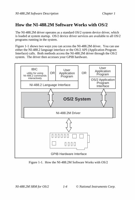
How the NI-488.2M Software Works with OS/2
The NI-488.2M driver operates as a standard OS/2 system device driver, whichis loaded at system startup. OS/2 device driver services are available to all OS/2programs running in the system.
Figure 1-1 shows two ways you can access the NI-488.2M driver. You can useeither the NI-488.2 language interface or the OS/2 API (Application ProgramInterface) calls. Both methods access the NI-488.2M driver through the OS/2system. The driver then accesses your GPIB hardware.
OS/2 System
NI-488.2M Driver
GPIB Hardware Interface
ORUser
Application Program
IBICutility for using
NI-488.2 commands interactively
NI-488.2 Language Interface
OR
User Application Program
OS/2 Application Program Interface
Figure 1-1. How the NI-488.2M Software Works with OS/2

Chapter 1 NI-488.2M Software Description
© National Instruments Corp. 1-5 NI-488.2M SRM for OS/2
The remainder of this chapter discusses the basics of GPIB and how to set upyour system. For application program examples, refer to Chapter 2, ApplicationExamples. For information about writing an application program, refer toChapter 3, Developing Your Application.
GPIB Overview
The following sections describe the elements of a GPIB system.
The IEEE 488 Standard and GPIB
The ANSI/IEEE Standard 488.1-1987, IEEE Standard Digital Interface forProgrammable Instrumentation, describes a standard interface forcommunication between instruments and controllers from various vendors. Itcontains information about electrical, mechanical, and functional specifications.The ANSI/IEEE Standard 488.2-1987, Codes, Formats, Protocols, andCommon Commands, defines a bus communication protocol, a common set ofdata codes and formats, and a generic set of common device commands.
The GPIB (General Purpose Interface Bus) is a digital, 8-bit parallelcommunications interface with data transfer rates of 1 Mbytes/s and above. Thebus supports one System Controller, usually a computer, and up to 14 additionalinstruments.
Talkers, Listeners, and Controllers
Devices on the GPIB can be Talkers, Listeners, or Controllers. A Talker sendsout data messages. Listeners receive data messages. The Controller, usually acomputer, manages the flow of information on the bus. It defines thecommunication links and sends GPIB commands to devices.
Some devices are capable of playing more than one role. A digital voltmeter,for example, can be a Talker and a Listener. If your personal computer has aGPIB interface board and GPIB software installed, it can function as a Talker,Listener, and Controller.

NI-488.2M Software Description Chapter 1
NI-488.2M SRM for OS/2 1-6 © National Instruments Corp.
Controller-In-Charge and System Controller
You can have multiple Controllers on the GPIB, but only one Controller at atime can be the active Controller, or Controller-In-Charge (CIC). When aController is not active, it is considered an idle Controller. Active control canpass from the current CIC to an idle Controller. The System Controller, usuallya GPIB interface board, is the only device on the bus that can make itself theCIC.
Sending Messages Across the GPIB
Devices on the bus communicate by sending messages. Signals and linestransfer these messages across the GPIB interface, which consists of 16 signallines and 8 ground return (shield drain) lines. The 16 signal lines are discussedin the following sections.
Data Lines
Eight data lines, DIO1 through DIO8, carry both data and command messages.
Handshake Lines
Three hardware handshake lines asynchronously control the transfer of messagebytes between devices. This process is a three-wire interlocked handshake, andit guarantees that devices send and receive message bytes on the data lineswithout transmission error. Table 1-1 summarizes the GPIB handshake lines.
Table 1-1. GPIB Handshake Lines
Line Description
NRFD (not ready for data) Listening device is ready/not ready toreceive a message byte.
NDAC (not data accepted) Listening device has/has not accepted amessage byte.
DAV (data valid) Talking device indicates signals on datalines are stable (valid) data.

Chapter 1 NI-488.2M Software Description
© National Instruments Corp. 1-7 NI-488.2M SRM for OS/2
Interface Management Lines
Five GPIB hardware lines manage the flow of information across the bus.Table 1-2 summarizes the GPIB interface management lines.
Table 1-2. GPIB Interface Management Lines
Line Description
ATN (attention) Controller drives ATN true when it sendscommands and false when it sends datamessages.
IFC (interface clear) System Controller drives the IFC line toinitialize the bus and make itself CIC.
REN (remote enable) System Controller drives the REN line toplace devices in remote or local programmode.
SRQ (service request) Any device can drive the SRQ line toasynchronously request service from theController.
EOI (end or identify) Talker uses the EOI line to mark the end ofa data message. Controller uses the EOIline when it conducts a parallel poll.
Setting Up and Configuring Your System
Devices are usually connected with a cable assembly consisting of a shielded24-conductor cable with both a plug and receptacle connector at each end. Withthis design, you can link devices in a linear configuration, a star configuration,or a combination of the two. Figure 1-2 shows the linear and starconfigurations.

NI-488.2M Software Description Chapter 1
NI-488.2M SRM for OS/2 1-8 © National Instruments Corp.
Device B
Device C
Device ALinear
Configuration
Device D
Device CDevice B
Device A
StarConfiguration
Figure 1-2. Linear and Star System Configuration

Chapter 1 NI-488.2M Software Description
© National Instruments Corp. 1-9 NI-488.2M SRM for OS/2
Controlling More Than One Board
Multiboard drivers, such as the NI-488.2M driver for OS/2, can control morethan one interface board. Figure 1-3 shows an example of a multiboard systemconfiguration.
Printer
Plotter
Digital Voltmeter
gpib0
gpib1
OneGPIB
AnotherGPIB
Figure 1-3. Example of Multiboard System Setup
gpib0 is the access board for the voltmeter, and gpib1 is the access board forthe plotter and printer. The control functions of the devices automatically accesstheir respective boards.

© National Instruments Corp. 2-1 NI-488.2M SRM for OS/2
Chapter 2Application Examples
This chapter contains nine sample applications designed to illustrate specificGPIB concepts and techniques that can help you write your own applications.The description of each example includes the programmer’s task, a programflowchart, and numbered steps that correspond to the numbered blocks on theflowchart.
Use this chapter along with your distribution disk, which contains theC source code for each of the nine examples. If you are new to GPIBprogramming, you might want to study the contents and concepts of thefirst sample, simple.c , before moving on to more complex examples.
• simple.c is the source code file for Example 1. It illustrates how you canestablish communication between a host computer and a GPIB device.
• clr_trg.c is the source code file for Example 2. It illustrates how youcan clear and trigger GPIB devices.
• asynch.c is the source code file for Example 3. It illustrates how you canperform non-GPIB tasks while data is being transferred over the GPIB.
• eos.c is the source code file for Example 4. It illustrates the concept of theend-of-string (EOS) character.
• rqs.c is the source code file for Example 5. It illustrates how you cancommunicate with GPIB devices that use the GPIB SRQ line to requestservice. This sample is written by using NI-488 functions.
• easy4882.c is the source code file for Example 6. It is an introduction toNI-488.2 routines.
• rqs4882.c is the source code file for Example 7. It uses NI-488.2routines to communicate with GPIB devices that use the GPIB SRQ line torequest service.
• ppoll.c is the source code file for Example 8. It uses NI-488.2 routines toconduct parallel polls.
• non_cic.c is the source code file for Example 9. It illustrates how youcan use the NI-488.2M driver in a non-Controller application.

Application Examples Chapter 2
NI-488.2M SRM for OS/2 2-2 © National Instruments Corp.
Example 1: Basic Communication
This example focuses on the basics of establishing communication between ahost computer and a GPIB device.
A technician needs to monitor voltage readings using a GPIB multimeter. Hiscomputer is equipped with an IEEE 488.2 interface board. The NI-488.2Msoftware is installed and a GPIB cable runs from the computer to the GPIB porton the multimeter.
The technician is familiar with the multimeter remote programming commandset. This list of commands is specific to his multimeter and is available from themultimeter manufacturer.
He sets up the computer to direct the multimeter to take measurements and recordeach measurement as it occurs. To do this, he has written an application that usessome simple high-level GPIB commands. The following steps correspond to theprogram flowchart in Figure 2-1.
1. The application initializes the GPIB by bringing the interface board in thecomputer online.
2. The application sends the multimeter an instruction, setting it up to takevoltage measurements in autorange mode.
3. The application sends the multimeter an instruction to take a voltagemeasurement.
4. The application tells the multimeter to transmit the data it has acquired to thecomputer.
The process of requesting a measurement and reading from the multimeter(Steps 3 and 4) is repeated as long as there are readings to be obtained.
5. As a cleanup step before exiting, the application returns the interface boardback to its original state by taking it offline.

Chapter 2 Application Examples
© National Instruments Corp. 2-3 NI-488.2M SRM for OS/2
Computer Multimeter
INIT
Read Measurement
from Multimeter
Finished Getting Measurements?
CLEAN UP
Yes
No
ibwrt
ibrd
"VOLTS?"Tell Multimeter to Take Measurement
"+ 5 volts"
1
2
3
5
Set Up Multimeter to Take Voltages
ibwrt
"VOLTS DC;AUTO"
4
GPIB Cable
Figure 2-1. Program Flowchart for Example 1

Application Examples Chapter 2
NI-488.2M SRM for OS/2 2-4 © National Instruments Corp.
Example 2: Clearing and Triggering Devices
This example illustrates how you can clear and trigger GPIB devices.
Two freshman physics lab partners are learning how to use a GPIB digitaloscilloscope. They have successfully loaded the NI-488.2M software on apersonal computer and connected their GPIB board to a GPIB digitaloscilloscope. Their current lab assignment is to write a small application topractice using the oscilloscope and its command set using high-level GPIBcommands. The following steps correspond to the program flowchart in Figure2-2.
1. The application initializes the GPIB by bringing the interface board in thecomputer online.
2. The application sends a GPIB clear command to the oscilloscope. Thiscommand clears the internal registers of the oscilloscope, reinitializing it todefault values and settings.
3. The application sends a command to the oscilloscope telling it to read awaveform each time it is triggered. Predefining the task in this waydecreases the execution time required. Each trigger of the oscilloscope isnow sufficient to get a new run.
4. The application sends a GPIB trigger command to the oscilloscope. TheGPIB trigger command causes the oscilloscope to acquire data.
5. The application queries the oscilloscope for the acquired data. Theoscilloscope sends the data.
6. The application reads the data from the oscilloscope.
7. The application calls an external graphics routine to display the acquiredwaveform.
Steps 4, 5, 6, and 7 are repeated until all the desired data has been acquiredby the oscilloscope and received by the computer.
8. As a cleanup step before exiting, the application returns the interface boardto its original state by taking it offline.

Chapter 2 Application Examples
© National Instruments Corp. 2-5 NI-488.2M SRM for OS/2
GPIB Cable
Computer Oscilloscope
INIT
Trigger Oscilloscope to
Get Reading
Finished Reading?
CLEAN UP
Yes
No
ibclr
ibtrg
Clear Command
Request Data from
Oscilloscope"CURV?"
Clear Oscilloscope
ibwrt
Define Task to Be Done When Oscilloscope is
Triggered
Trigger Command
1
2
3
4
5
6Read Data
from Oscilloscope
DisplayWaveform
Data
7
8
"WAV=TRIG"
ibwrt
ibrd
Figure 2-2. Program Flowchart for Example 2

Application Examples Chapter 2
NI-488.2M SRM for OS/2 2-6 © National Instruments Corp.
Example 3: Asynchronous I/O
This example illustrates how an application conducts data transfers with a GPIBdevice and immediately returns to perform other non-GPIB related tasks whileGPIB I/O is occurring in the background. This asynchronous mode of operationis particularly useful when the requested GPIB activity may take some time tocomplete.
In this example, a research biologist is trying to obtain accurate CAT scans of alab animal’s liver. She will print out a color copy of each scan as it is acquired.The entire operation is computer controlled. The CAT scan machine sends theimages it acquires to a computer connected to a GPIB color printer and fittedwith the NI-488.2M software package. The biologist is familiar with thecommand set of her color printer, as described in the user manual provided by themanufacturer. She acquires and prints images with the aid of an applicationprogram she wrote using high-level GPIB commands. The following stepscorrespond to the program flowchart in Figure 2-3.
1. The application initializes the GPIB by bringing the interface board in thecomputer online.
2. An image is scanned in.
3. The application sends the GPIB printer a command to print the new imageand immediately returns without waiting for the I/O operation to becompleted.
4. The application saves the image obtained to a file.
5. The application inquires as to whether the printing operation has completedby issuing a GPIB wait command. If the status reported by the waitcommand indicates completion (CMPL is in the status returned) and morescans need to be acquired, Steps 2 through 5 are repeated until the scans haveall been acquired. If the status reported by the wait command in Step 5 doesnot indicate that printing is finished, statistical computations are performedon the scan obtained and Step 5 is repeated.
6. As a cleanup step before exiting, the application returns the interface boardback to its original state by taking it offline.

Chapter 2 Application Examples
© National Instruments Corp. 2-7 NI-488.2M SRM for OS/2
Computer
INIT
Print Image Asynchronously
CLEAN UP
Non-GPIB Activity: Save
to Disk
Color Printer
Print Image
Image Scan
Non-GPIB Activity: Compute Statistics
More Images?
Yes
No
Yes
No
ibwrta
1
2
3
4
5
6
GPIB Cable
Is GPIB Printing Done?
ibwait
Figure 2-3. Program Flowchart for Example 3

Application Examples Chapter 2
NI-488.2M SRM for OS/2 2-8 © National Instruments Corp.
Example 4: End-of-String Mode
This example illustrates how to use the end-of-string modes to detect that theGPIB device has finished sending data.
A journalist is using a GPIB scanner to scan some pictures into his personalcomputer for a news story. A GPIB cable runs between the scanner and thecomputer. He is using an application written by an intern in the department whohas read the instruction manual provided by the scanner manufacturer and isfamiliar with its programming requirements. The following steps correspond tothe program flowchart in Figure 2-4.
1. The application initializes the GPIB by bringing the interface board in thecomputer online.
2. The application sends a GPIB clear message to the scanner, initializing it toits power-on defaults.
3. The scanner needs to see a delimiter indicating the end of a command. Inthis case, the scanner expects the commands to be terminated with<CR><LF> (carriage return, \r , and linefeed, \n ). The application sets itsend-of-string (EOS) byte to <LF>. The linefeed code indicates to thescanner that there is no more data coming, and is called the end-of-stringbyte. It flags an end-of-string condition for this particular GPIB scanner.The same effect could be accomplished by asserting the EOI line when thecommand is sent.
4. With the exception of the scan resolution, all the default settings areappropriate for the task at hand. The application changes the scan resolutionby writing the appropriate command to the scanner.
5. The scanner sends back information describing the status of the changeresolution command. This is a string of bytes terminated by theend-of-string character to tell the application it is done changing theresolution.
6. The application starts the scan by writing the scan command to the scanner.
7. The application reads the scan data into the computer.
8. As a cleanup step before exiting, the application returns the interface boardback to its original state by taking it offline.

Chapter 2 Application Examples
© National Instruments Corp. 2-9 NI-488.2M SRM for OS/2
Read Status
Computer Scanner
INIT
Set EOS Mode
CLEAN UP
ibclr
ibeos
Change Scan
Resolution
Reset Internal State
"RES:3 \ r \ n"
ibwrt
Read Data
ibwrt
ibrd
Start Scan
"OK"
"scan \ r \ n"
Scanned Data
ibrd
1
2
3
4
5
6
7
8
Clear Command
GPIB Cable
Figure 2-4. Program Flowchart for Example 4

Application Examples Chapter 2
NI-488.2M SRM for OS/2 2-10 © National Instruments Corp.
Example 5: Service Requests
This example illustrates how an application communicates with a GPIB devicethat uses the GPIB service request (SRQ) line to indicate that it needs attention.
A graphic arts designer is transferring digital images stored on her computer to aroll of color film by using a GPIB digital film recorder. A GPIB cable connectsthe GPIB port on the film recorder to the IEEE 488.2 interface board installed inher computer. She has installed the NI-488.2M software package on the hostcomputer and is familiar with the programming instructions for the film recorder,as described in the user manual provided by the manufacturer. She places a freshroll of film in the camera and launches a simple application she has written usinghigh-level GPIB commands. With the aid of the application, she records a fewimages on film. The following steps correspond to the program flowchart inFigure 2-5.
1. The application initializes the GPIB by bringing the interface board in thecomputer online.
2. The application brings the film recorder to a ready state by issuing a deviceclear instruction. The film recorder is now set up for operation using itsdefault values. (The graphic arts designer has previously established that thedefault values for the film recorder are appropriate for the type of film she isusing.)
3. The application advances the new roll of film into position so the first imagecan be exposed on the first frame of film. This is done by sending theappropriate instructions as specified in the film recorder programming guide.
4. The application, by waiting for RQS (request for service), waits for the filmrecorder to signify that it is done loading the film. The film recorder assertsthe GPIB SRQ line when it has finished loading the film.
5. As soon as the film recorder asserts the GPIB SRQ line, the application’swait for the RQS event completes. The application serial polls the device bysending a special command message to the film recorder that directs it toreturn a response in the form of a serial poll status byte. This byte containsinformation indicating what kind of service the film recorder is requesting orwhat condition it is flagging. In this example, it indicates the completion ofa command.

Chapter 2 Application Examples
© National Instruments Corp. 2-11 NI-488.2M SRM for OS/2
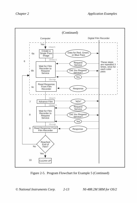
6. A color image transfers to the digital film recorder in three consecutivepasses—one pass each for the red, green and blue components of the image.Sub-steps a, b, and c are repeated for each of the passes:
a. The application sends a command to the film recorder, directing it toaccept data to create a single pass image. The film recorder asserts theSRQ line as soon as a pass is completed.
b. The application waits for RQS.
c. When the SRQ line is asserted, the application serial polls the filmrecorder to see whether it requested service, as in Step 5.
7. The application issues a command to the film recorder to advance the film byone frame. The advance occurs successfully unless the end of film isreached.
8. The application waits for RQS, which completes when the film recorderasserts the SRQ line to signal it is done advancing the film.
9. As soon as the application’s wait for RQS completes, the application serialpolls the film recorder to see whether it requested service, as in Step 5. Thereturned serial poll status byte indicates either of two conditions: the filmrecorder finished advancing the film, as requested, or the end of film wasreached and it can no longer advance. Steps 6 through 9 are repeated as longas film is in the camera and more images need to be recorded.
10. As a cleanup step before exiting, the application returns the interface boardback to its original state by taking it offline.

Application Examples Chapter 2
NI-488.2M SRM for OS/2 2-12 © National Instruments Corp.
GPIB Cable
Computer Digital Film Recorder
INIT
Wait for theFilm Recorder toRequest Service
Finished Loading
Film?
ibclr
ibwait
"FRM+"
Read Response from
the Film Recorder
Response
Advance Film
Clear Film Recorder Clear Command
ibrsp
1
2
4
3
5
No
ibwrt
YesExit Application and Repair
Film Recorder
Request Service
Did You Request Service ?
Yes
(continues)
Figure 2-5. Program Flowchart for Example 5
Chapter 2 Application Examples
© National Instruments Corp. 2-13 NI-488.2M SRM for OS/2
(Continued)
CLEAN UP
Yes
Wait for Film Recorder to
Request Service
Create a Single Pass
Image
Read Response From Film Recorder
ibrsp
Wait for Film Recorder to
Request Service
Advance Film
Read Response From Film Recorder
6
6a
6b
6c
7
8
9
10
Yes
ibwaitThese steps are repeated 3 times, once for each color pass
ibwrt
ibwait
Reached End of Film?No
Computer Digital Film Recorder
ibrsp
ibwrt
Data for Red, Green, or Blue Pass
Request Service
Did You Request Service?
Yes
Response
"ADV"
Request Service
Did You Request Service?
Yes
Response
Figure 2-5. Program Flowchart for Example 5 (Continued)

Application Examples Chapter 2
NI-488.2M SRM for OS/2 2-14 © National Instruments Corp.
Example 6: Basic Communication withIEEE 488.2 Compliant Devices
This example provides an introduction to communicating with IEEE 488.2compliant devices.
A test engineer in a metal factory is using IEEE 488.2 compliant tensile testers tofind out the strength of metal rods as they come out of production. There areseveral tensile testers and they are all connected to a central computer equippedwith an IEEE 488.2 interface board. These machines are fairly voluminous and itis difficult for the engineer to reach the address switches of each machine. Forthe purposes of his future work with these tensile testers, he needs to determinewhat GPIB addresses they have been set to. He can do so with the aid of a simpleapplication he has written. The following steps correspond to the programflowchart in Figure 2-6.
1. The application initializes the GPIB by bringing the interface board in thecomputer online.
2. The application issues a command to detect the presence of listening deviceson the GPIB and compiles a list of the addresses of all such devices.
3. The application sends an identification query (“*IDN?” ) to a devicedetected on the GPIB in Step 2.
4. The application reads the identification information returned by the device asit responds to the query in Step 3.
Steps 3 and 4 are repeated for each of the devices detected in Step 2.
5. As a cleanup step before exiting, the application returns the interface boardback to its original state by taking it offline.

Chapter 2 Application Examples
© National Instruments Corp. 2-15 NI-488.2M SRM for OS/2
Computer Tensile Tester 1
INIT
Tell Device to Identify Itself
CLEAN UP
FindLstn
Send
"*IDN?"
Receive
Tensile Tester 2 Tensile Tester 3
Who's Listening?
Get a List of Devices Present on
GPIB
Device 1 is Here
Device 2 is Here
Device 3 is Here
"MUTT 10426"
"MUTT 10528"
1
2
3
4
5
"MUTT 10383"
GPIB Cable GPIB Cable GPIB Cable
Receive
Receive
Read Response
from Device 2
Read Response
from Device 3
Tell Device 2 to Identify
Itself
Tell Device 3 to Identify
Itself
Send
Send
"*IDN?"
"*IDN?"
Read Response
from Device 1
3
4
3
4
Figure 2-6. Program Flowchart for Example 6

Application Examples Chapter 2
NI-488.2M SRM for OS/2 2-16 © National Instruments Corp.
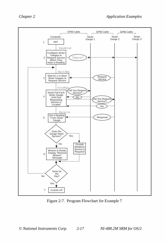
Example 7: Serial Polls Using NI-488.2 Routines
This example illustrates how you can take advantage of the NI-488.2 routines toreduce the complexity of performing serial polls of multiple devices.
A candy manufacturer is using GPIB strain gauges to measure the consistency ofthe syrup used to make candy. The plant has four big mixers containing syrup.The syrup has to reach a certain consistency to make good quality candy. Theconsistency is measured by strain gauges that monitor the amount of pressureused to move the mixer arms. When a certain consistency is reached, the mixtureis removed and a new batch of syrup is poured in the mixer. The GPIB straingauges are connected to a computer equipped with an IEEE 488.2 interface boardand fitted with the NI-488.2M software. The process is controlled by anapplication that uses NI-488.2 routines to communicate with the IEEE 488.2compliant strain gauges. The following steps correspond to the programflowchart inFigure 2-7.
1. The application initializes the GPIB by bringing the interface board in thecomputer online.
2. The application configures the strain gauges to request service when theyhave a significant pressure reading or a mechanical failure occurs. Theysignal their request for service by asserting the SRQ line.
3. The application waits for one or more of the strain gauges to indicate thatthey have a significant pressure reading. This wait event ends as soon as theSRQ line is asserted.
4. The application serial polls each strain gauge to see if it requested service.
5. Once the application has determined which strain gauge requires service, ittakes a reading from that strain gauge.
6. If the reading matches the desired consistency, a dialog window appears onthe computer screen and prompts the mixer operator to remove the mixtureand start a new batch. Otherwise, a dialog window prompts the operator toservice the mixer in some other way.
Steps 3 through 6 are repeated as long as the mixers are in operation.
7. After the last batch of syrup has been processed, the application returns theinterface board to its original state by taking it offline.
Chapter 2 Application Examples
© National Instruments Corp. 2-17 NI-488.2M SRM for OS/2
Computer Strain Gauge 1
INIT
CLEAN UP
SendList
WaitSRQ
FindRQS
Strain Gauge 2
Strain Gauge 3
Request Service
Receive
Done for the
Day?
1
7
GPIB Cable GPIB CableGPIB Cable
Yes
No
Wait for 1 or More Strain Gauges to Request Service
3
NoDid You Request
Service?
Did You Request Service?
Yes
Serial Poll Each Strain Gauge
Until One Requesting Service is Located
4
ResponseGet a Reading
From Strain Gauge
5
No
Yes
Provide Whatever Service is Required
Does the Gauge Need
Service?
6
Mixture is Ready.Display "Remove
Mixture" Message
"SRQ=HI"
Configure Strain Gauges to
Request Service When They
Have a Reading
2
Figure 2-7. Program Flowchart for Example 7

Application Examples Chapter 2
NI-488.2M SRM for OS/2 2-18 © National Instruments Corp.
Example 8: Parallel Polls
This example illustrates how you can use NI-488.2 routines to obtain informationfrom several IEEE 488.2 compliant devices at once by using a procedure calledparallel polling.
The process of manufacturing a particular alloy involves bringing three differentmetals to specific temperatures before mixing them to form the alloy. Three vatsare used, each containing a different metal. Each is monitored by a GPIB oremonitoring unit. The monitoring unit consists of a GPIB temperature transducerand a GPIB power supply. The temperature transducer is used to probe thetemperature of each metal. The power supply is used to start a motor to pour themetal into the mold when it reaches a predefined temperature. The threemonitoring units are connected to the IEEE 488.2 interface board of a computerfitted with the NI-488.2M software and operated by an application using NI-488.2 routines. The application obtains information from the multiple units byconducting a parallel poll, then determines when to pour the metals into themixture tank. The following steps correspond to the program flowchart in Figure2-8.
1. The application initializes the GPIB by bringing the interface board in thecomputer online.
2. The application configures the temperature transducer in the first monitoringunit by choosing which of the eight GPIB data lines the transducer uses torespond when a parallel poll is conducted. The application also sets thetemperature threshold. The transducer manufacturer has defined theindividual status (ist ) bit to be true when the temperature threshold isreached, and the configured status mode of the transducer is assert the dataline. When a parallel poll is conducted, the transducer asserts its data line ifthe temperature has exceeded the threshold.
3. The application configures the temperature transducer in the secondmonitoring unit for parallel polls.
4. The application configures the temperature transducer in the third monitoringunit for parallel polls.
5. The application conducts non-GPIB activity while the metals are heated.

Chapter 2 Application Examples
© National Instruments Corp. 2-19 NI-488.2M SRM for OS/2
6. The application conducts a parallel poll of all three temperature transducersto determine whether the metals have reached the appropriate temperature.Each transducer asserts its data line during the configuration step if itstemperature threshold has been reached.
7. If the response to the poll indicates that all three metals are at the appropriatetemperature, the application sends a command to each of the three powersupplies, directing them to power on. Then the motors start and the metalspour into the mold.
If only one or two of the metals is at the appropriate temperature,Steps 5 and 6 are repeated until the metals can be successfully mixed.
8. The application unconfigures all the transducers so that they no longerparticipate in parallel polls.
9. As a cleanup step before exiting, the application returns the interface boardback to its original state by taking it offline.

Application Examples Chapter 2
NI-488.2M SRM for OS/2 2-20 © National Instruments Corp.
Computer
INIT
CLEAN UP
PPollConfig
Configure Transducer 3
for Parallel Polls
Non-GPIB Activity
Parallel Poll Enable
Start Power Supplies
No
Temp Transducer
Yes
1
2
3
4
5
6
7
9
PPollConfig
PPollConfig
PPoll Unconfigure8
PPoll
"MIX ON"SendList
PPollUnconfig
Power Supply
Configure Transducer 2
for Parallel Polls
Configure Transducer 1 for
Parallel Polls
UNIT 1
GPIB CableGPIB Cable
GPIB Cable
GPIB Cable
GPIB Cable
GPIB Cable
Are All Metals Ready?
Yes
Temp Transducer
Power Supply
UNIT 2Temp
TransducerPower Supply
UNIT 3
Parallel Poll Enable
YesYes
Parallel Poll Enable
Parallel Poll
Parallel Poll Disable
Figure 2-8. Program Flowchart for Example 8

Chapter 2 Application Examples
© National Instruments Corp. 2-21 NI-488.2M SRM for OS/2
Example 9: Non-Controller Example
This example illustrates how you can use the NI-488.2M software to emulate aGPIB device that is not the GPIB Controller.
A software engineer has written firmware to emulate a GPIB device for aresearch project and is testing it by using an application that makes simple GPIBcalls. The following steps correspond to the program flowchart in Figure 2-9.
1. The application brings the device online.
2. The application waits for any of three events to occur: the device becomeslisten addressed, becomes talk addressed, or receives a GPIB clear message.
3. As soon as one of the events occurs, the application takes an action basedupon the event that occurred. If the device was cleared, the applicationresets the internal state of the device to default values. If the device is talkaddressed, it writes data back to the Controller. If the device is listenaddressed, it reads in new data from the Controller.

Application Examples Chapter 2
NI-488.2M SRM for OS/2 2-22 © National Instruments Corp.
Device Controller
INIT
Wait to be Talk Addressed,
Listen Addressed, or
Cleared
Write Out New Data
No
ibwait
fffffffffff
Is This the Clear Event?
Is This the Talk
Addressed Event?
Reset Internal State Yes
Yes
Data
No
Read In New Data
Data
ibwrt
ibrd
1
2
3
3
3
Figure 2-9. Program Flowchart for Example 9
© National Instruments Corp. 3-1 NI-488.2M SRM for OS/2
Chapter 3Developing Your Application
This chapter explains how to develop a GPIB application program using NI-488functions and NI-488.2 routines.
Choosing a Programming Method
Programs that need to communicate across the GPIB can access the NI-488.2Mdriver using either the NI-488.2 language interface or the OS/2 API calls.
Using the NI-488.2 Language Interface
One method of programming the NI-488.2M driver is with an NI-488.2language interface using functions defined by National Instruments. The NI-488functions and NI-488.2 routines are an industry standard and are portable acrossmany computer platforms and operating systems. In most cases, you should usethese functions and routines because they are designed to make GPIBprogramming easier. You also should use them if you are already using otherNational Instruments GPIB products, because the same format and syntax workregardless of the GPIB hardware product. You can make NI-488 or NI-488.2calls in the ibic interactive program or from your application program.
When using the NI-488.2 interface, your OS/2 application runs with both theAT-GPIB driver for OS/2 and MC-GPIB driver for OS/2 without modificationor recompiling. Also, multiple applications can share the same library. The NI-488.2M software for OS/2 includes language interface libraries for IBM CSet,Borland C/C++ for OS/2, and Microsoft C 6.0. If you are not programming withone of these languages, you should use the OS/2 API interface.
Your distribution disk contains two distinct sets of subroutines to meet yourapplication needs. Both of these sets, the NI-488 functions and the NI-488.2routines, are compatible across computer platforms and operating systems, soyou can port programs to other platforms with little or no source code

Developing Your Application Chapter 3
NI-488.2M SRM for OS/2 3-2 © National Instruments Corp.
modification. For most application programs, the NI-488 functions aresufficient. You should use the NI-488.2 routines if you have a complexconfiguration with one or more interface boards and multiple devices.Regardless of which option you choose, the driver automatically addresses andperforms other bus management operations necessary for device communication.
The following sections discuss some differences between NI-488 functions andNI-488.2 routines.
Using NI-488 Functions: One Device for Each Board
If your system has only one device attached to each board, the NI-488 functionsare probably sufficient for your programming needs. Some other factors thatmake the NI-488 functions more convenient include the following:
• With NI-488 asynchronous I/O functions (ibcmda , ibrda , and ibwrta ),you can initiate an I/O sequence while maintaining control over the CPU fornon-GPIB tasks.
• NI-488 functions include built-in file transfer functions (ibrdf andibwrtf ).
• The NI-488 function ibconfig dynamically changes the GPIB driverconfiguration without the need to run the ibconf utility.
• With NI-488 functions, you can control the bus in non-typical ways orcommunicate with noncompliant devices.
The NI-488 functions consist of high-level (or device) functions that hide muchof the GPIB management operations and low-level (or board) functions that offeryou more control over the GPIB than NI-488.2 routines. The following sectionsdescribe these different function types.
NI-488 Device-Level Functions
Device-level functions are high-level functions that automatically executecommands that handle bus management operations such as reading fromand writing to devices or polling them for status. If you use device-levelfunctions, you do not need to understand GPIB protocol or bus management.For information about device-level calls and how they manage the GPIB, refer toDevice-Level Calls and Bus Management, in Chapter 6, GPIB ProgrammingTechniques.

Chapter 3 Developing Your Application
© National Instruments Corp. 3-3 NI-488.2M SRM for OS/2
NI-488 Board-Level Functions
Board-level functions are low-level functions that perform rudimentary GPIBoperations. Board-level functions access the interface board directly and requireyou to handle the addressing and bus management protocol.In cases when the device-level functions might not meet your needs,board-level functions give you the flexibility and control to handle situationssuch as the following:
• Communicating with noncompliant (non-IEEE 488.2) devices
• Altering various low-level board configurations
• Managing the bus in non-typical ways
The NI-488 board-level functions are compatible with, and can be interspersedwithin, sequences of NI-488.2 routines. When you useboard-level functions within a sequence of NI-488.2 routines, you do not need aprior call to ibfind . You simply substitute the board index asthe first parameter of the board-level function call. With this flexibility, you canhandle non-standard or unusual situations that you cannot resolve usingNI-488.2M routines only.
Using NI-488.2 Routines: Multiple Boards and/or Multiple Devices
When your system includes a board that must access more than one device, usethe NI-488.2 routines. NI-488.2 routines can perform the following tasks with asingle call:
• Find all of the Listeners on the bus
• Configure the attached instruments
• Find a device requesting service
• Determine the state of the SRQ line
• Wait for SRQ to be asserted
• Address multiple devices

Developing Your Application Chapter 3
NI-488.2M SRM for OS/2 3-4 © National Instruments Corp.
• Specify board index, GPIB address, and termination parameters so that youdo not need to remember device names, unit descriptors, or terminationmodes separately
• Use routine names that are descriptive of their purpose
Using the OS/2 API Interface
If the NI-488.2 interface does not meet your requirements, you can access theNI-488.2M driver through the OS/2 API interface. This interface uses the OS/2standard device driver interface instead of a particular language interface.Because this interface is supported by all devices, you can use it with alldevelopment environments. Using the API interface, however, is not as easy asusing the NI-488.2 interface. Refer to Chapter 3, Application Program InterfaceFunction, in the NI-488.2M Function Reference Manual for OS/2, for moreinformation about the API functions.
Checking Status with Global Variables
Each NI-488 function and NI-488.2 routine updates the global variables to reflectthe status of the device or board that you are using. The status word (ibsta ),the error variable (iberr ), and the count variables (ibcnt and ibcntl )contain useful information about the performance of your application program.Your program should check these variables frequently. The following sectionsdescribe each of these global variables and how you can use them in yourapplication program.
Status Word—ibsta
All functions update a global status word, ibsta , which contains informationabout the state of the GPIB and the GPIB hardware. The value stored in ibstais the return value of all NI-488 functions except ibfind and ibdev . You cantest for the conditions reported in ibsta and use that information to makedecisions about continued processing. Also, if you check for possible errors aftereach call, debugging your application is much easier.
ibsta is a 16-bit value. A bit value of 1 indicates that a certain condition is ineffect. A bit value of 0 indicates that the condition is not in effect. Each bit inibsta can be set for device calls (dev), board calls (brd), or both (dev, brd).

Chapter 3 Developing Your Application
© National Instruments Corp. 3-5 NI-488.2M SRM for OS/2
Table 3-1 shows the condition that each bit position represents, the mnemonicrepresentation of each bit, and the type of calls for which the bit is set. For adetailed explanation of each of the status conditions, refer to Appendix A, StatusWord Conditions.
MnemonicBitPos.
HexValue Type Description
ERR 15 8000 dev, brd GPIB error
TIMO 14 4000 dev, brd Time limit exceeded
END 13 2000 dev, brd END or EOS detected
SRQI 12 1000 brd SRQ interrupt received
RQS 11 800 dev Device requesting service
CMPL 8 100 dev, brd I/O completed
LOK 7 80 brd Lockout State
REM 6 40 brd Remote State
CIC 5 20 brd Controller-In-Charge
ATN 4 10 brd Attention is asserted
TACS 3 8 brd Talker
LACS 2 4 brd Listener
DTAS 1 2 brd Device Trigger State
DCAS 0 1 brd Device Clear State
The language header files included on your distribution disk contain themnemonic constants for ibsta . You can check a bit position in ibsta byusing its numeric value or its mnemonic constant. For example, bit position 15(hex 8000) detects a GPIB error. The mnemonic for this bit is ERR. To checkfor a GPIB error, use either of the following statements after each NI-488function and NI-488.2 routine:
if (ibsta & ERR) gpiberr();
or
if (ibsta & 0x8000) gpiberr();
where gpiberr() is an error-handling routine that you have defined.
Table 3-1. Status Word (ibsta) Layout
Developing Your Application Chapter 3
NI-488.2M SRM for OS/2 3-6 © National Instruments Corp.
Error Variable—iberr
If the ERR bit is set in the status word (ibsta ), a GPIB error has occurred.When an error occurs, the error type is specified by the value in iberr .
Note: The value in iberr is meaningful as an error type only when theERR bit is set, indicating that an error has occurred.
For more information on error codes and solutions, refer to Chapter 4,Debugging Your Application, or Appendix B, Error Codes and Solutions.
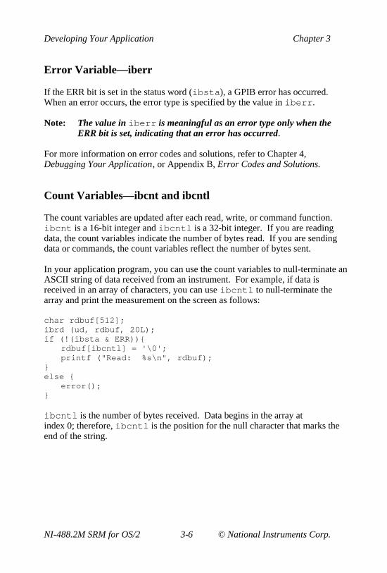
Count Variables—ibcnt and ibcntl
The count variables are updated after each read, write, or command function.ibcnt is a 16-bit integer and ibcntl is a 32-bit integer. If you are readingdata, the count variables indicate the number of bytes read. If you are sendingdata or commands, the count variables reflect the number of bytes sent.
In your application program, you can use the count variables to null-terminate anASCII string of data received from an instrument. For example, if data isreceived in an array of characters, you can use ibcntl to null-terminate thearray and print the measurement on the screen as follows:
char rdbuf[512];ibrd (ud, rdbuf, 20L);if (!(ibsta & ERR)){
rdbuf[ibcntl] = '\0';printf ("Read: %s\n", rdbuf);
}else {
error();}
ibcntl is the number of bytes received. Data begins in the array atindex 0; therefore, ibcntl is the position for the null character that marks theend of the string.

Chapter 3 Developing Your Application
© National Instruments Corp. 3-7 NI-488.2M SRM for OS/2
Using ibic to Communicate with DevicesBefore you begin writing your application program, you might want to use theibic utility. With ibic (Interface Bus Interactive Control), you communicatewith your instruments from the keyboard rather than from an applicationprogram. You can use ibic to learn to communicate with your instrumentsusing the NI-488 functions or NI-488.2 routines. For specific devicecommunication instructions, refer to the user manual that came with yourinstrument. For information about using ibic and for detailed examples, referto Chapter 5, ibic—Interface Bus Interactive Control Utility.
After you have learned how to communicate with your devices in ibic , you areready to begin writing your application program.
Writing Your NI-488 Application
This section discusses items you should include in your application program,general program steps, and examples.
Items to Include
• Include the GPIB header file. This file contains prototypes for theNI-488 functions and constants that you can use in your applicationprogram. Include the declaration file appropriate for your compiler asfollows:
#include "decl.h" /* 32-bit C compiler */
#include "decl_16.h" /* 16-bit C compiler */
• Check for errors after each NI-488 function call.
• Declare and define a function to handle GPIB errors. This function takes thedevice offline and closes the application. If the function is declared asfollows
void gpiberr (char *msg); /* function prototype */
your application invokes the function as follows
if (ibsta & ERR) {gpiberr("GPIB error");
}

Developing Your Application Chapter 3
NI-488.2M SRM for OS/2 3-8 © National Instruments Corp.
NI-488 Program Shell
Figure 3-1 is a flowchart of the steps to create your application program usingNI-488 functions. The flowchart is for device-level calls.
No
Yes
No
No
Closed All Boards/Devices?
Yes
START
orOpen Board/Device by Specifying Name (ibfind)
Open Device without Knowing Device Name (ibdev)
Are All Boards/Devices
Open?
Make a Device-Level Call• Send Data to Device• Receive Data from Device• Clear Device• Serial Poll Device and so on
(ibwrt)(ibrd)
(ibclr)(ibrsp)
Finished GPIB Programming?
Close Board or Device (ibonl)
END
Yes
Figure 3-1. General Program Shell Using NI-488 Device Functions

Chapter 3 Developing Your Application
© National Instruments Corp. 3-9 NI-488.2M SRM for OS/2
General Program Steps and Examples
The following steps demonstrate how to use the NI-488 device functions in yourprogram. This example configures a digital multimeter, reads 10 voltagemeasurements, and computes the average of these measurements.
Step 1. Open a Device
Your first NI-488 function call should be to ibfind or ibdev to open adevice.
ud = ibdev(0, 1, 0 , 12, 1, 0);
if (ibsta & ERR) { gpiberr("ibdev error");}
The input arguments of the ibdev function are as follows:
0 – Board index for gpib0
1 – Primary GPIB address of the device
0 – No secondary GPIB address for the device
12 – I/O timeout value (3 s)
1 – Send END message with the last byte when writing to the device
0 – Disable EOS detection mode
When you call ibdev , the driver automatically initializes the GPIB by sendingan Interface Clear (IFC) message and placing the device in the remoteprogramming state.
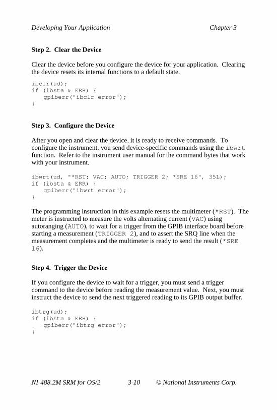
Developing Your Application Chapter 3
NI-488.2M SRM for OS/2 3-10 © National Instruments Corp.
Step 2. Clear the Device
Clear the device before you configure the device for your application. Clearingthe device resets its internal functions to a default state.
ibclr(ud);if (ibsta & ERR) {
gpiberr("ibclr error");}
Step 3. Configure the Device
After you open and clear the device, it is ready to receive commands. Toconfigure the instrument, you send device-specific commands using the ibwrtfunction. Refer to the instrument user manual for the command bytes that workwith your instrument.
ibwrt(ud, "*RST; VAC; AUTO; TRIGGER 2; *SRE 16", 35L);if (ibsta & ERR) {
gpiberr("ibwrt error");}
The programming instruction in this example resets the multimeter (*RST). Themeter is instructed to measure the volts alternating current (VAC) usingautoranging (AUTO), to wait for a trigger from the GPIB interface board beforestarting a measurement (TRIGGER 2), and to assert the SRQ line when themeasurement completes and the multimeter is ready to send the result (*SRE16).
Step 4. Trigger the Device
If you configure the device to wait for a trigger, you must send a triggercommand to the device before reading the measurement value. Next, you mustinstruct the device to send the next triggered reading to its GPIB output buffer.
ibtrg(ud);if (ibsta & ERR) {
gpiberr("ibtrg error");}

Chapter 3 Developing Your Application
© National Instruments Corp. 3-11 NI-488.2M SRM for OS/2
ibwrt(ud,"VAL1?", 5L);if (ibsta & ERR) {
gpiberr("ibwrt error");}
Step 5. Wait for the Measurement
After you trigger the device, the RQS bit is set when the device is ready to sendthe measurement. You can detect RQS by using the ibwait function. Thesecond parameter indicates what you are waiting for. Notice that the ibwaitfunction also returns when the I/O timeout value is exceeded.
printf("Waiting for RQS...\n");if (ibwait (ud, TIMO| RQS) & (ERR | TIMO)) {
gpiberr("ibwait error");}
When SRQ has been detected, serial poll the instrument to determine whether themeasured data is valid or whether a fault condition exists. For IEEE 488.2instruments, you can find out by checking the message available (MAV) bit,which is bit 4 in the status byte that you receive from the instrument.
ibrsp (ud, &StatusByte);if (ibsta & ERR) {
gpiberr("ibrsp error");}
if ( !(StatusByte & MAVbit)) {gpiberr("Improper Status Byte");printf(" Status Byte = 0x%x\n", StatusByte);
}

Developing Your Application Chapter 3
NI-488.2M SRM for OS/2 3-12 © National Instruments Corp.
Step 6. Read the Measurement
If the data is valid, read the measurement from the instrument.(AsciiToFloat is a function that takes a null-terminated string as input andoutputs the floating point number it represents.)
ibrd (ud, rdbuf, 10L);if (ibsta & ERR) {
gpiberr("ibrd error");}
rdbuf[ibcntl] = '\0';printf("Read: %s\n", rdbuf);
/* Output ==> Read: +10.98E-3 */
sum += AsciiToFloat(rdbuf);
Step 7. Process the Data
Repeat Steps 4 through 6 in a loop until 10 measurements have been read, thenprint the average of the readings as shown:
printf("The average of the 10 readings is %f\n", sum/10.0);
Step 8. Place the Device Offline
As a final step, take the device offline by using the ibonl function.
ibonl (ud, 0);

Chapter 3 Developing Your Application
© National Instruments Corp. 3-13 NI-488.2M SRM for OS/2
Writing Your NI-488.2 Application
This section discusses items you should include in an application program thatuses NI-488.2 routines, general program steps, and examples.
Items to Include
• Include the GPIB header file. This file contains prototypes for the NI-488.2routines and constants that you can use in your application program. Includethe declaration file appropriate for your compiler as follows:
#include "decl.h" /* 32-bit C compiler */
#include "decl_16.h"/* 16-bit C compiler */
• Check for errors after each NI-488.2 routine.
• Declare and define a function to handle GPIB errors. This function takes theboard offline and closes the application. If the function is declared asfollows
void gpiberr (char *msg); /* function prototype */
your application invokes the function as follows
if (ibsta & ERR) {gpiberr("GPIB error");
}

Developing Your Application Chapter 3
NI-488.2M SRM for OS/2 3-14 © National Instruments Corp.
NI-488.2 Program Shell
Figure 3-2 is a flowchart of the steps to create your application program usingNI-488.2 routines.
No
END
Make a High-Level CallMake a Low-Level Call
No
• Send Data to Device (Send)• Receive Data from Device (Receive )• Clear Device (DevClear )• Serial Poll Device (ReadStatusByte ) and so on
• Address Devices to Listen (SendSetup )• Send Data to Addressed Listener (SendDataBytes )• Address Device to Talk (ReceiveSetup )• Receive Data from Addressed Talker (RcvRespMsg) and so on
Low-Level High-Level
Yes
Close Board (ibonl )
Are All Boards Closed?
Finished GPIB Programming?
Making High-Level or
Low-Level Call?
Initialize Specified GPIB Interface (SendIFC )
START
Yes
Are All Boards Open?
Yes
No
Figure 3-2. General Program Shell Using NI-488.2 Routines

Chapter 3 Developing Your Application
© National Instruments Corp. 3-15 NI-488.2M SRM for OS/2
General Program Steps and Examples
The following steps demonstrate how to use the NI-488.2 routines in yourprogram. This example configures a digital multimeter, reads 10 voltagemeasurements, and computes the average of these measurements.
Step 1. Initialization
Use the SendIFC routine to initialize the bus and the GPIB interface board sothat the GPIB board is CIC. The only argument of SendIFC is the GPIBinterface board number.
SendIFC(0);if (ibsta & ERR) {
gpiberr("SendIFC error");}
Step 2. Find All Listeners
Create an array of all the instruments attached to the GPIB. Use the FindLstnroutine. The first argument is the interface board number, the second argumentis the list of instruments that was created, the third argument is a list ofinstrument addresses that the procedure actually found, and the last argument isthe maximum number of devices that the procedure may find (that is, it muststop if it reaches the limit). The end of the list of addresses must be marked withthe NOADDR constant, which is defined in the header file that you included at thebeginning of the program.
for (loop = 0; loop <=30; loop++){instruments[loop] = loop;
}instruments[31] = NOADDR;
printf("Finding all Listeners on the bus...\n");
Findlstn(0, instruments, result, 30);if (ibsta & ERR) {
gpiberr("FindLstn error");}

Developing Your Application Chapter 3
NI-488.2M SRM for OS/2 3-16 © National Instruments Corp.
Step 3. Identify the Instrument
Send an identification query to each device for identification. For this example,assume that all the instruments are IEEE 488.2 compatible and can accept theidentification query, *IDN? . In addition, assume that FindLstn found theGPIB interface board at primary address 0 (default) and, therefore, you can skipthe first entry in the result array.
for (loop = 1; loop <= num_Listeners; loop++) {Send(0, result[loop], "*IDN?", 5L, NLend);if (ibsta & ERR) {
gpiberr("Send error");}
Receive(0, result[loop], buffer, 10L, STOPend); if (ibsta & ERR) {
gpiberr("Receive error");}
buffer[ibcntl] = '\0';printf("The instrument at address %d is a %s\n",
result[loop], buffer);if (strncmp(buffer, "Fluke, 45", 9) == 0) {
fluke = result[loop];printf("**** Found the Fluke ****\n");break;
}}
if (loop > num_Listeners) {printf("Did not find the Fluke!\n");
}
The constant NLend signals that the new line character with EOI isautomatically appended to the data to be sent.
The constant STOPend indicates that the read is stopped when EOI is detected.

Chapter 3 Developing Your Application
© National Instruments Corp. 3-17 NI-488.2M SRM for OS/2
Step 4. Initialize the Instrument
After you find the multimeter, use the DevClear routine to clear it. The firstargument is the GPIB board number. The second argument is the GPIB addressof the multimeter. Next, send the IEEE 488.2 Reset command to the meter.
DevClear(0, fluke);if (ibsta & ERR) {
gpiberr("DevClear error")}
Send(0, fluke, "*RST", 4L, NLend);if (ibsta & ERR) {
gpiberr("Send *RST error");}
Step 5. Configure the Instrument
After initialization, the instrument is ready to receive instructions. To configurethe multimeter, use the Send routine to send device-specific commands. Thefirst argument is the number of the access board. The second argument is theGPIB address of the multimeter. The third argument is a string of bytes to sendto the multimeter.
The bytes in this example instruct the meter to measure volts alternating current(VAC) using autoranging (AUTO), to wait for a trigger from the Controllerbefore starting a measurement (TRIGGER 2), and to assert SRQ when themeasurement has been completed and the meter is ready to send the result(*SRE 16 ). The fourth argument represents the number of bytes to be sent.The last argument, NLend, is a constant defined in the header file that tellsSend to append a linefeed character with EOI asserted to the end of themessage sent to the multimeter.
Send (0, fluke, "VAC; AUTO; TRIGGER 2; *SRE 16", 29L, NLend);if (ibsta & ERR) {
gpiberr("Send setup error");}

Developing Your Application Chapter 3
NI-488.2M SRM for OS/2 3-18 © National Instruments Corp.
Step 6. Trigger the Instrument
In the previous step, the multimeter was instructed to wait for a trigger beforeconducting a measurement. Now send a trigger command to the multimeter.You could use the Trigger routine to accomplish this, but because the Fluke45 is IEEE 488.2 compatible, you can just send it the trigger command, *TRG.The VAL1? command instructs the meter to send the next triggered reading toits output buffer.
Send(0, fluke, "*TRG; VAL1?", 11L, NLend);if (ibsta & ERR) {
gpiberr("Send trigger error");}
Step 7. Wait for the Measurement
After the meter is triggered, it takes a measurement and displays it on its frontpanel, then asserts SRQ. You can detect the assertion of SRQ by using eitherthe TestSRQ or WaitSRQ routine. If you have a process that you want toexecute while you are waiting for the measurement, use TestSRQ. For thisexample, you can use the WaitSRQ routine. The first argument in WaitSRQ isthe GPIB board number. The second argument is a flag returned by WaitSRQ.This flag indicates whether SRQ is asserted.
WaitSRQ(0, &SRQasserted);if (!SRQasserted) {
gpiberr("WaitSRQ error");}
After you have detected SRQ, use the ReadStatusByte routine to poll themeter and determine its status. The first argument is the GPIB board number,the second argument is the GPIB address of the instrument, and the lastargument is a variable that ReadStatusByte uses to store the status byte ofthe instrument.
ReadStatusByte(0, fluke, &statusByte);if (ibsta & ERR) {
gpiberr("ReadStatusByte error");}

Chapter 3 Developing Your Application
© National Instruments Corp. 3-19 NI-488.2M SRM for OS/2
After you have obtained the status byte, you must check to see if the meter has amessage to send. You can do this by checking the message available (MAV)bit, bit 4, in the status byte.
if (!(statusByte & MAVbit) {gpiberr("Improper Status Byte");printf("Status Byte = 0x%x\n", statusByte);
}
Step 8. Read the Measurement
Use the Receive function to read the measurement over the GPIB. The firstargument is the GPIB interface board number, and the second argument is theGPIB address of the multimeter. The third argument is a string into which theReceive function places the data bytes from the multimeter. The fourthargument represents the number of bytes to be received. The last argumentindicates that the Receive message terminates upon receiving a byteaccompanied with the END message.
Receive(0, fluke, buffer, 10L, STOPend);if (ibsta & ERR) {
gpiberr("Receive error");}
buffer[ibcntl] = '\0';printf (Reading : %s\n", buffer);sum += AsciiToFloat(buffer);} /* end of loop started in Step 5 */
Step 9. Process the Data
Repeat Steps 5 through 8 in a loop until 10 measurements have been read, thenprint the average of the readings as shown:
printf (" The average of the 10 readings is : %f\n", sum/10);

Developing Your Application Chapter 3
NI-488.2M SRM for OS/2 3-20 © National Instruments Corp.
Step 10. Place the Board Offline
Before ending your application program, take the board offline by usingthe ibonl function.
ibonl(0,0);
Compiling and Linking Your Program
After you have written your application program, you need to compile yourprogram and link it with the language interface.
Make sure that the full pathname of the import library that you are using(ni488.lib , nibor.lib , or ni488_16.lib ) is included in the SET LIBconfiguration command in the config.sys file. For example, if the importlibrary is in a directory d:\at-gpib\c , the SET LIB configurationcommand may appear as follows:
SET LIB = d:\toolkt20\os2lib;d:\cset2\lib;d:\at-gpib\c
32-Bit C Applications
Before you compile your application program, make sure that the following lineis included at the beginning of your program:
#include "decl.h"
Compile your 32-bit IBM C program by using the following command:
icc /c cprog.c
then enter the following command to link your compiled program with the NI-488.2 32-bit IBM C language interface:
link386 /NOI cprog.obj,,,ni488.lib;

Chapter 3 Developing Your Application
© National Instruments Corp. 3-21 NI-488.2M SRM for OS/2
Compile your 32-bit Borland C program using the following command:
bcc /c cprog.c
then enter the following command to link your compiled program with the NI-488.2 32-bit Borland C language interface:
tlink /c /Toe c02.obj cprog.obj,,,os2.lib c2mti.libnibor.lib;
16-Bit C Applications
Before you compile your application program, make sure that the following lineis included at the beginning of the program:
#include "decl_16.h"
Compile your 16-bit program by using the following command:
cl /c cprog.c
then enter the following command to link your compiled program with the NI-488.2 16-bit C language interface:
link /NOI cprog.obj,,,ni488_16.lib;
Running Your Application Program
After you have compiled and linked your application program, you can beginusing it. Make sure that the full pathname of the DLL that you are using(ni488.dll , nibor.lib , or ni488_16.dll) is included in theLIBPATH statement in your config.sys file. For example, if the DLL is in adirectory d:\at-gpib\c , the LIBPATH configuration command may appearas follows:
LIBPATH=.;d:\os2\dll;d:\os2\mdos;d:\;d:\at-gpib\c;
If you discover errors when you execute the program, refer to Chapter 4,Debugging Your Application.

© National Instruments Corp. 4-1 NI-488.2M SRM for OS/2
Chapter 4Debugging Your Application
This chapter describes several ways to debug your application program.
Running ibtest
Presence Test of Driver
The following message appears in response to any of four situations:
<<< No driver present for GPIB x. >>>
• The ibtest program always tries to test the four AT-GPIB boards. Inmost cases, you have fewer than four boards installed in your computer.The above message appears when ibtest tries to test a board that does notexist. You can ignore this message when it applies to a nonexistent board.
• The GPIB driver might not be installed. To correct this situation, makecertain that the line device=y:\at-gpib\gpib.sys —where y refersto the letter of the drive where the NI-488.2M software is installed—is inyour config.sys file, then reboot.
• The Use this GPIB Interface field in ibconf might be set to nofor board GPIBx . If you want to use this board, you must set this field toyes .
Before you run your application program, you should run the softwarediagnostic test, ibtest , that came with your NI-488.2M software. Theibtest program is an NI-488.2M application that makes calls to the driver. Ifibtest passes, your GPIB hardware and NI-488.2M software are interactingcorrectly. The following paragraphs describe the messages you might receivewhile running ibtest and how to resolve each problem. The term GPIBxrefers to one of the boards GPIB0, GPIB1, GPIB2, and GPIB3.

Debugging Your Application Chapter 4
NI-488.2M SRM for OS/2 4-2 © National Instruments Corp.
• GPIBx might be configured to use the same interrupt level that is alreadyused by another device in the system. This situation would cause a conflictthat would prevent the driver from installing GPIBx . Try a differentinterrupt level and make certain that the hardware and software areconfigured to use the same level.
Presence Test of GPIB Board
The following error message appears if GPIBx is not installed or if it is notconfigured at the base I/O address that the driver expects:
<<< No board present for GPIB x. >>>
Check that the board is properly installed in your computer and run ibconf tomake certain that the driver is configured to use the same base I/O address as theboard.
Incorrect Interrupt Level
The ibtest program outputs dots, then hangs if the AT-GPIB board under testis installed but configured to use an incorrect interrupt level. Run ibconf toconfigure the driver to use the correct interrupt level.
GPIB Cables Connected
The following error message appears if a GPIB cable was connected to the boardwhen you ran ibtest :
Call(25) 'ibcmd “ “' failed, ibsta (0x134) not whatwas expected (0x8130)
Call(25) 'ibcmd “ “' failed, expected ibsta (0x100) tohave the ERR bit set.
Disconnect all GPIB cables before trying the test again.
Chapter 4 Debugging Your Application
© National Instruments Corp. 4-3 NI-488.2M SRM for OS/2
Debugging with the Global Status Variables
After each function call to your NI-488.2M driver, ibsta , iberr , and ibcntare updated before the call returns to your application. You should check for anerror after each GPIB call. Refer to Chapter 3, Developing Your Application,for more information about how to use these variables within your program toautomatically check for errors.
After you determine which GPIB call is failing and note the correspondingvalues of the global variables, refer to Appendix A, Status Word Conditions,and Appendix B, Error Codes and Solutions. These appendixes will help youinterpret the state of the driver.
Debugging with ibic
If your application does not automatically check for and display errors, you canlocate an error by using ibic . Simply issue the same functions or routines,one at a time, as they appear in your application program. Because ibicreturns the status values and error codes after each call, you should be able todetermine which GPIB call is failing. For more information about ibic , referto Chapter 5, ibic—Interface Bus Interactive Control Utility.
After you determine which GPIB call is failing and note the correspondingvalues of the global variables, refer to Appendix A, Status Word Conditions,and Appendix B, Error Codes and Solutions. These appendixes will help youinterpret the state of the driver.
GPIB Error Codes
Table 4-1 lists the GPIB error codes. Remember that the error variableis meaningful only when the ERR bit in the status variable is set. For a detaileddescription of each error and possible solutions, refer to Appendix B, ErrorCodes and Solutions.

Debugging Your Application Chapter 4
NI-488.2M SRM for OS/2 4-4 © National Instruments Corp.
Table 4-1. GPIB Error Codes
ErrorMnemonic
iberrValue Meaning
EDVR 0 OS/2 error
ECIC 1 Function requires GPIB board to be CIC
ENOL 2 No Listeners on the GPIB
EADR 3 GPIB board not addressed correctly
EARG 4 Invalid argument to function call
ESAC 5 GPIB board not System Controller asrequired
EABO 6 I/O operation aborted (timeout)
ENEB 7 Nonexistent GPIB board
EOIP 10 Asynchronous I/O in progress
ECAP 11 No capability for operation
EFSO 12 File system error
EBUS 14 GPIB bus error
ESTB 15 Serial poll status byte queue overflow
ESRQ 16 SRQ stuck in ON position
ETAB 20 Table problem
Configuration Errors
If your hardware and software settings do not match, one of the followingproblems might occur:
• Application hangs on input or output functions
• Data is corrupted
If these problems occur, make sure that the GPIB hardware settings match theNI-488.2M software settings for the interrupt request level and the DMAchannel. For information on hardware and software default settings, refer to thegetting-started manual that came with your kit. The next section discusses howto reconfigure your NI-488.2M software, if necessary.

Chapter 4 Debugging Your Application
© National Instruments Corp. 4-5 NI-488.2M SRM for OS/2
Reconfiguring the NI-488.2M Software
Several applications require customized configuration of the GPIB driver. Forexample, you might want to terminate reads on a special end-of-string character,or you might require secondary addressing. In these cases, you can use eitherthe ibconf utility to permanently reconfigure the driver, or you can use thedynamic configuration function call ibconfig to modify the driver whileyour application is running.
ibconfig does not permanently change the state of the driver. Usingdynamic configuration automatically configures the driver as necessary.
Note: To change settings other than base I/O address, interrupt level, orDMA channel, National Instruments recommends using ibconfiginstead of running the ibconf utility .
If your program uses dynamic configuration, it will always work regardless ofthe previous driver configuration. For more information, refer to the descriptionof ibconfig in the NI-488.2M Function Reference Manual for OS/2.
Timing Errors
If your application fails but the same calls issued in ibic are successful, yourprogram might be issuing the NI-488.2 calls too quickly for your device toprocess and respond to them. This problem can also result in corrupted orincomplete data.
A well-behaved IEEE 488 device should hold off handshaking and set theappropriate transfer rate. If your device is not well behaved, you can test forand resolve the timing error by single-stepping through your program andinserting finite delays between each GPIB call. One way to perform this actionis to have your device communicate its status whenever possible. Although thismethod is not possible with many devices, it is usually the best option. Yourdelays will be controlled by the device and your application can adjust itself andwork independently on any platform. Other delay mechanisms will probablycause varying delay times on different platforms.

Debugging Your Application Chapter 4
NI-488.2M SRM for OS/2 4-6 © National Instruments Corp.
Communication Errors
Repeat Addressing
Some devices require GPIB addressing before any GPIB activity. Devicesadhering to the IEEE 488.2 standard should remain in their current state untilspecific commands are sent across the GPIB to change their state. You mightneed to configure your NI-488.2M driver to perform repeat addressing if yourdevice does not remain in its currently addressed state. Refer to Chapter 7,ibconf—Interface Bus Configuration Utility, or to the description of ibconfigin the NI-488.2M Function Reference Manual for OS/2 for more informationabout reconfiguring your software.
Termination Method
You should be aware of the termination method that your device uses. Bydefault, your NI-488.2M software is configured to send EOI on writes andterminate reads on EOI or a specific byte count. If you send a command stringto your device and the device does not respond, it may not recognize the end ofthe command. You may need to send a termination message, such as <CR><LF>, after a write command, as follows:
ibwrt(dev,”COMMAND\x0A\x0D”,9);

© National Instruments Corp. 5-1 NI-488.2M SRM for OS/2
Chapter 5ibic—Interface Bus Interactive ControlUtility
This chapter introduces you to ibic , the interactive control program that youcan use to communicate with GPIB devices through functions you enter at yourkeyboard.
Overview
With the Interface Bus Interactive Control (ibic ) program, you communicatewith the GPIB devices through functions you enter at the keyboard. For specificcommunication instructions, refer to the manual that came with your instrument.You can use ibic to practice communication with the instrument, troubleshootproblems, and develop your application program.
One way ibic helps you to learn about your instrument and to troubleshootproblems is by displaying the following information on your computer screenwhenever you enter a command:
• The results of the status word (ibsta ) in hexadecimal.
• The mnemonic constant of each bit set in ibsta .
• The mnemonic value of the error variable (iberr ) if an error exists (theERR bit is set in ibsta ).
• The count value for each read, write, or command function.
• The data received from your instrument.

ibic—Interface Bus Interactive Control Utility Chapter 5
NI-488.2M SRM for OS/2 5-2 © National Instruments Corp.
Starting ibic
The ibic program is contained in ibic.exe , the executable file that wascopied from your distribution disk when you installed the NI-488.2M software.To run ibic , change to the appropriate subdirectory (AT-GPIB in the followingexample) and enter ibic at the prompt as shown:
C:/AT-GPIB>
National InstrumentsIEEE-488 Interface Bus Interactive Control Program (IBIC)Copyright (c) 1993 National Instruments Corp. Version 2.0Version Date: Apr 30 1993 Version Time: 09:42:25All Rights Reserved
Press 'help' for help or 'q' to quit.
ibic
Exiting ibic
Typing e or q terminates execution of the ibic program.
ibic Syntax
The syntax of functions in ibic differs from the syntax in a programminglanguage. The main difference is that in ibic , certain messages (ibwrt ,ibwrta , ibrd , ibrda , ibcmd , ibcmda , Send, SendList , andSendCmds) are entered as strings from the keyboard.
Another difference is that the board or device descriptor (ud) is not explicitlypart of ibic function syntax. Before using any device or board, first callibfind to open that unit. ibic uses the descriptor returned by the driver for

Chapter 5 ibic—Interface Bus Interactive Control Utility
© National Instruments Corp. 5-3 NI-488.2M SRM for OS/2
all subsequent calls to that unit. When the device or board is opened, thesymbolic name of that device or board is added to the prompt.
The ibic utility makes no distinction between uppercase and lowercase.
Tables 5-1 and 5-2 summarize the syntax of NI-488 functions and NI-488.2routines that are called from ibic . Syntax rules for the functions and routinesin ibic are explained in the table notes.
Table 5-1. Syntax for NI-488 Functions in ibic
Syntax Description Type Note
ibask mna Return configuration information dev, brd 16
ibbnabrdname
Change access board of device dev 1
ibcac [v] Become active Controller brd 2,3
ibclr Clear specified device dev
ibcmd string Send commands from string brd 4
ibcmdastring
Send commands asynch. from string brd 4
ibconfig mnv
Alter configurable parameters dev, brd 15,3
ibdev vvvvvv Open an unused device when thedevice name is unknown
dev 9
ibdma [v] Enable/disable DMA brd 2,3
ibeos v Change/disable EOS message dev, brd 3
ibeot [v] Enable/disable END message dev, brd 2,3
ibfindudname
Return unit descriptor dev, brd 5
ibgts [v] Go from active Controller to standby brd 2,3
ibist [v] Set/clear ist brd 2,3
iblines Read the state of all GPIB lines dev, brd
ibln v v Check for presence of device of bus dev, brd 10
ibloc Go to local dev, brd
(continues)

ibic—Interface Bus Interactive Control Utility Chapter 5
NI-488.2M SRM for OS/2 5-4 © National Instruments Corp.
Table 5-1. Syntax for NI-488 Functions in ibic (Continued)
Syntax Description Type Note
ibonl [v] Place device online or offline dev, brd 2,3
ibpad v Change primary address dev, brd 3
ibpct Pass control dev
ibppc v Parallel poll configure dev, brd 3
ibrd v Read data dev, brd 6
ibrda v Read data asynchronously dev, brd 6
ibrdf flname Read data to file dev, brd 7
ibrpp Conduct a parallel poll dev, brd
ibrsc [v] Request/release system control brd 2,3
ibrsp Return serial poll byte dev
ibrsv v Request service dev 3
ibsad v Change secondary address dev, brd 3
ibsic Send interface clear brd
ibsre [v] Set/clear remote enable line brd 2,3
ibstop Abort asynchronous operation dev, brd
ibtmo v Change/disable time limit dev, brd 3
ibtrg Trigger selected device dev
ibwait[mask]
Wait for selected event dev, brd 2,8
ibwrt string Write data brd 4
ibwrtastring
Write data asynchronously dev, brd 4
ibwrtfflname
Write data from a file dev, brd 7

Chapter 5 ibic—Interface Bus Interactive Control Utility
© National Instruments Corp. 5-5 NI-488.2M SRM for OS/2
Table 5-2. Syntax for NI-488.2 Routines in ibic
Routine Syntax Description Note
AllSpoll list Serial poll multiple devices 11
DevClear address Clear a device 13
DevClearList list Clear multiple devices 11
EnableLocal list Enable local control 11
EnableRemote list Enable remote control 11
FindLstn list v Find all Listeners 3,11
FindRQS list Find device asserting SRQ 11
PassControl address Pass control to a device 13
PPoll Parallel poll devices
PPollConfig addr . line sense Configure device forparallel poll
13,14
PPollUnconfig address Unconfigure device forparallel poll
13
RcvRespMsg address data mode Receive response message 4,12,13
ReadStatusByte address Serial poll a device 13
Receive address data mode Receive data from a device 4,12,13
ReceiveSetup address Receive setup 13
ResetSys list Reset multiple devices 11
Send address data mode Send data to a device 4,12,13
SendCmds data Send command bytes 4
SendDataBytes list data mode Send data bytes 4,11,12
SendIFC Send interface clear
SendList list data mode Send data to multipledevices
4,11,12
SendLLO Put devices in local lockout
(continues)

ibic—Interface Bus Interactive Control Utility Chapter 5
NI-488.2M SRM for OS/2 5-6 © National Instruments Corp.
Table 5-2. Syntax for NI-488.2 Routines in ibic (Continued)
Routine Syntax Description Note
SendSetup list Send setup 11
Set 488.2 v Enter into 488.2 mode forboard
SetRWLS list Put device in remote withlockout state
11
TestSys list Cause multiple devices toperform self tests
11
TestSRQ Test for service request
Trigger address Trigger a device 13
TriggerList list Trigger multiple devices 11
WaitSRQ Wait for service request

Chapter 5 ibic—Interface Bus Interactive Control Utility
© National Instruments Corp. 5-7 NI-488.2M SRM for OS/2
Notes for Tables 5-1 and 5-2
1. brdname is the symbolic name of the new board (for example, gpib1 ).
2. Values enclosed in square brackets ([] ) are optional. The default valueis 0 for ibwait and 1 for all other functions.
3. v is a hex, octal, or decimal integer. Hex numbers must be preceded by 0and x (for example, 0xD). Octal numbers must be preceded by 0 only(for example, 015). Other numbers are assumed to be decimal.
4. string consists of a list of ASCII characters, octal or hex bytes, orspecial symbols. You must enclose the entire sequence of characters inquotation marks. An octal byte consists of a backslash character followedby the octal value. For example, octal 40 is represented by \40 . A hexbyte consists of a backslash character and a character x followed by thehex value. For example, hex 40 is represented by \x40 . The two specialsymbols, \r for a carriage return character and \n for a linefeedcharacter, are a more convenient method for inserting the carriage returnand linefeed characters into the string, as shown in the followingexample: "F3R5T1\r\n" . Because the carriage return is representedequally well in hex, \xD and \r are equivalent strings.
5. udname is the symbolic name of the new device or board (for example,dev1 or gpib0 ).
6. v is the number of bytes to read.
7. flname is the path name of the file to be read or written (for example,\test\meter or printr.buf ).
8. mask is a hex, octal, or decimal integer (see note 3), or a mask bitmnemonic.
9. ibdev parameters are board id , pad , sad , tmo , eos , and eot .
10. ibln parameters are pad and sad .

ibic—Interface Bus Interactive Control Utility Chapter 5
NI-488.2M SRM for OS/2 5-8 © National Instruments Corp.
11. list is a comma-separated list of address integers, optionally enclosedin parentheses. An empty list can be expressed by empty parentheses.
12. mode is a termination mode mnemonic or integer. Mnemonics areNLend, DABend, and NULLend for send operations, and STOPend forreceive operations.
13. address is an integer representing a GPIB address. If only a primaryGPIB address is required, enter that integer. If a secondary address isalso required, create an integer with the primary address in the low-orderbyte, and the secondary address in the high-order byte; for example,pad 3 and sad 0x61 could be expressed as 0x6103.
14. line and sense are integers representing the data line to respond onand the sense of the response.
15. mn is a mnemonic for a configuration parameter or the equivalent integervalue. Refer to the description of ibconfig in the NI-488.2M FunctionReference Manual for OS/2 for the allowed mnemonics and their values.
16. mna is a mnemonic for a configuration parameter or the equivalentinteger value. Refer to the description of ibask in the NI-488.2MFunction Reference Manual for OS/2 for the allowed mnemonics andtheir values.

Chapter 5 ibic—Interface Bus Interactive Control Utility
© National Instruments Corp. 5-9 NI-488.2M SRM for OS/2
Adding End-of-String Characters
Some GPIB instruments require special termination characters or end-of-string(EOS) characters to indicate to the device that a transmission has ended. If yourdevice requires any EOS characters, you must add these to the end of the datastring sent out by the ibwrt statement. The following example illustrates theaddition of the two most commonly used EOS characters: the carriage returnand the linefeed.
dev1:[0100] (cmpl)count: 8
ibwrt "F3R5T1\r\n"
The \r and \n represent the carriage return and linefeed characters,respectively. Refer to Appendix A, Multiline Interface Messages, in theNI-488.2M Function Reference Manual for OS/2 for more information aboutnon-printable characters.
Status Word Return
In ibic , all NI-488 functions (except ibfind and ibdev ) and NI-488.2routines return the status word ibsta in two forms: a hex value in squarebrackets and a list of mnemonics in parentheses. In the following example, thestatus word shows that the device function write operation completedsuccessfully.
dev1:[0100] (cmpl)count: 5
dev1:
ibwrt "f2t3x"

ibic—Interface Bus Interactive Control Utility Chapter 5
NI-488.2M SRM for OS/2 5-10 © National Instruments Corp.
For more information about the status word, refer to Chapter 3, Developing YourApplication.
Error Codes Return
If an NI-488 function or NI-488.2 routine completes with an error, ibicdisplays the error mnemonic. The following example illustrates the result if anerror condition occurs in a data transfer.
dev1:[8100] (err cmpl)error: ENOLcount: 1
dev1:
ibwrt "f2t3x"
In this example, there are no Listeners, indicating that dev1 is powered off orthe GPIB cable is disconnected. For a detailed list of the error codes and theirmeanings, refer to Chapter 4, Debugging Your Application.
Count Return
When an I/O function completes, ibic displays the actual number of bytes sentor received, regardless of the existence of an error condition.
If one of the addresses in an address list of an NI-488.2 routine is invalid, ibicdisplays the index of the invalid address as the count.
The count return has a different meaning, depending on which NI-488 functionor NI-488.2 routine is called. Refer to the function descriptions in the NI-488.2M Function Reference Manual for OS/2 for the correct interpretation of thecount return.

Chapter 5 ibic—Interface Bus Interactive Control Utility
© National Instruments Corp. 5-11 NI-488.2M SRM for OS/2
Common NI-488.2 Routines in ibic
Use the auxiliary function set to select the NI-488.2 function mode. Thesyntax for this form of the set command is as follows:
set 488.2 [n]
where n represents an optional board number (for example, n = 1 for gpib1 ).The default value of n is 0 (gpib0 ).
After issuing this form of the set command, ibic uses the 488.2 prompt toindicate that you are in NI-488.2 mode on board n.
set 488.2 1
488.2 (1):
After issuing the set 488.2 command, you can use any of the NI-488.2routines.
Send
The Send routine sends data to a single GPIB device. You can use theSendList command to send data to multiple GPIB devices. For example,suppose you want to send the five-character string *IDN? followed by the newline character with EOI. You want to send the message from the computer tothe devices at primary address 2 and 17. To do this, enter the SendListcommand at the 488.2 (0): prompt.

ibic—Interface Bus Interactive Control Utility Chapter 5
NI-488.2M SRM for OS/2 5-12 © National Instruments Corp.
488.2 (0): SendList 2, 17 "*IDN?" NLend[0128] (cmpl cic tacs)count: 6
The returned status word [0128] indicates a successful I/O completion, whilethe byte count indicates that all six characters, including the added new line,were sent from the computer and received by both devices.
Receive
The Receive routine causes the GPIB board to receive data from anotherGPIB device. The following example illustrates the use of the Receiveroutine.
488.2 (0): Receive 5 10 STOPend[2124] (end cmpl cic lacs)count: 548 65 6c 6c 6f H e l l o
The command acquires data from the device at primary address 5. It stopsreceiving data when 10 characters have been received or when the ENDmessage is received. The acquired data is then displayed in hex format alongwith its ASCII equivalent. The ibic program also displays the status word andthe count of transferred bytes.

Chapter 5 ibic—Interface Bus Interactive Control Utility
© National Instruments Corp. 5-13 NI-488.2M SRM for OS/2
Common NI-488 Functions in ibic
ibfind
To execute any NI-488 function in ibic , you must first use ibfind to openthe device or board you want to communicate with. When the device or board isopened, the symbolic name of that device or board is added to the prompt. Theunit descriptor of a board or device is returned.
The following example shows ibfind opening dev1 .
:id = 32259
dev1:
ibfind dev1
The returned value is the unit descriptor of the board.
The name used with the ibfind function must be a valid symbolic nameknown by the driver. dev1 is the default name found in the driver. For moreinformation about valid names, refer to Chapter 7, ibconf—Interface BusConfiguration Utility.
ibdev
The ibdev command selects an unopened device, opens it, and initializes itsaccess board.

ibic—Interface Bus Interactive Control Utility Chapter 5
NI-488.2M SRM for OS/2 5-14 © National Instruments Corp.
With ibdev , you can input the values in the following fields:
• Access Board for the Device
• Primary Address
• Secondary Address
• Timeout Setting
• EOT mode
• EOS mode
The following example shows ibdev opening an available device andassigning it to access gpib0 (board = 0) with a primary address of 6 (pad =6), a secondary address of hex 67 (sad = 0x67), a timeout of 10 ms (tmo = 7),the END message enabled (eot = 1), and the EOS mode disabled (eos = 0).
: ibdev 0 6 0x67 7 1 0
id = 32259
ud0:

Chapter 5 ibic—Interface Bus Interactive Control Utility
© National Instruments Corp. 5-15 NI-488.2M SRM for OS/2
If you type ibdev at the prompt, ibic asks you for the input parameters, asshown in the following example.
: ibdev
ud0:
enter board index: 0enter primary address: 6enter secondary address: 0x67enter timeout: 7enter 'EOI on last byte' flag: 1enter end-of-string mode/byte: 0
id = 32259
Three distinct errors can occur with the ibdev call:
• EDVR – No device is available, the board index entered refers to anonexistent board—that is, not 0, 1, 2, or 3—or the board has no driverinstalled. The following example illustrates an EDVR error.
: ibdev 4 6 0x67 7 1 0
id = -1[8000] ( err )error: EDVR (2)
:
• ENEB – The board index entered refers to a known board (such as 0), butthe driver cannot find the board. In this case, run ibconf to verify that thebase address of the board is set correctly.
• EARG – One of the last five parameters is an illegal value. The ibdev callreturns with a new prompt and the EARG error (invalid function argument).If the ibdev call returns with an EARG error, you must identify whichparameter is incorrect and use the appropriate command to correct it. In thefollowing example, pad has an invalid value. You can correct it with anibpad call.

ibic—Interface Bus Interactive Control Utility Chapter 5
NI-488.2M SRM for OS/2 5-16 © National Instruments Corp.
: ibdev 0 66 0x67 7 1 0
[8100] ( err cmpl )error: EARG
ud0: ibpad 6previous value: 16
id=32261
ibwrt
The ibwrt command sends data from one GPIB device to another. Forexample, to send the six-character data string F3R5T1 from the computer to adevice called dev1 , you enter the following string at the dev1: prompt.
dev1: [0100] (cmpl)count: 6
ibwrt "F3R5T1"
The returned status word [0100] indicates a successful I/O completion, while thebyte count indicates that all six characters were sent from the computer andreceived by the device.

Chapter 5 ibic—Interface Bus Interactive Control Utility
© National Instruments Corp. 5-17 NI-488.2M SRM for OS/2
ibrd
The ibrd command causes a GPIB device to receive data from another GPIBdevice. The following example illustrates the use of the ibrd function.
dev1:[2100] (end cmpl)count: 184e 44 43 56 28 30 30 30 N D C V ( 0 0 02e 30 30 34 37 45 2b 30 . 0 0 4 7 E + 00d 0a • •
ibrd 20
This command acquires data from the device and displays it on the screen in hexformat and in its ASCII equivalent, along with information about the datatransfer, such as the status word and the byte count.

ibic—Interface Bus Interactive Control Utility Chapter 5
NI-488.2M SRM for OS/2 5-18 © National Instruments Corp.
Auxiliary Functions
Table 5-3 summarizes the auxiliary functions that you can use in ibic .
Table 5-3. Auxiliary Functions in ibic
Function Description Notes
set udname Select active device or board 1, 2
help [option] Display help information 3
! Repeat previous function
- Turn display off
+ Turn display on
n* function Execute function n times 4
n* ! Execute previous function n times
$ filename Execute indirect file 5
print string Display string on screen 6
buffer option Set the type of display used for buffers 7
e Exit or quit
q Exit or quit
Notes
1. udname is the symbolic name of the new device or board (for example,dev1 or gpib0 ).
2. Initially call ibfind to open each device or board.
3. If option is omitted, a menu of options appears.
4. Replace function with correct ibic function syntax.
5. filename is the path name of a file that contains ibic functions to beexecuted.

Chapter 5 ibic—Interface Bus Interactive Control Utility
© National Instruments Corp. 5-19 NI-488.2M SRM for OS/2
6. string consists of a list of ASCII characters, octal or hex bytes, or specialsymbols. You must enclose the entire sequence of characters in quotationmarks. An octal byte consists of a backslash character followed by the octalvalue. For example, octal 40 is represented by \040 . A hex byte consistsof a backslash character and a character x followed by the hex value. Forexample, hex 40 is represented by \x40 . The two special symbols, \r fora carriage return character and \n for a linefeed character, are a moreconvenient method for inserting the carriage return and linefeed charactersinto the string as shown in this example: "F3R5T1\r\n" . Because thecarriage return can be represented equally well in hex, \xD and \r areequivalent strings.
7. Valid options for buffer are 0, 1, 2, and 3, which denote off , ascii ,full , and brief , respectively.
Set (Select Device or Board)
Use the set command to change which device you are communicating with.
dev1:
plotter:
set plotter
This example assumes that you used ibconf to define the name plotter andthat you had already called ibfind plotter during an earlier ibic session.
The following example summarizes the use of ibfind and set in a typicalprogram.

ibic—Interface Bus Interactive Control Utility Chapter 5
NI-488.2M SRM for OS/2 5-20 © National Instruments Corp.
id=32260
dev1:id=32261
plotter:[0100] (cmpl)count: 6
plotter:
dev1:[0100] (cmpl)count: 7
dev1:
ibfind plotter
ibwrt "F3T7G0"
set dev1
ibwrt "X7Y39G0"
: ibfind dev1
When you open a device or board using ibfind , you can use the auxiliaryfunction set to select the opened device or board. set changes the prompt tothe new symbolic name. You can also use set to switch between NI-488 modeand NI-488.2 mode.
The argument udname represents any of the symbolic device or board namesrecognized by the driver. The default names are gpib0 , gpib1 , gpib2 , andgpib3 for boards, and dev1 through dev32 for devices (unless you havechanged the device names using ibconf ).
Help (Display Help Information)
The help function displays a menu of topics to choose from, where each topiclists relevant functions or codes. For example, the topic list1 lists all NI-488functions. The status topic lists all status word (ibsta) codes.
Help also gives information about the syntax of functions.

Chapter 5 ibic—Interface Bus Interactive Control Utility
© National Instruments Corp. 5-21 NI-488.2M SRM for OS/2
! (Repeat Previous Function)
The ! function repeats the most recent function executed. The followingexample issues an ibsic command, then repeats that same command asfollows.
ibsic gpib0:
[0130] (cmpl cic atn)
gpib0: !
(cmpl cic atn)[0130]
- (Turn OFF Display) and + (Turn ON Display)
The - function causes the bytes received not to be displayed on the screen. Thisfunction is useful when you want to repeat any I/O function quickly withoutwaiting for screen output to be displayed.
The + function causes the display to be restored.
The following example shows how the - and + functions are used. Twenty-fourconsecutive letters of the alphabet are read from a device using three ibrdcalls.

ibic—Interface Bus Interactive Control Utility Chapter 5
NI-488.2M SRM for OS/2 5-22 © National Instruments Corp.
dev1:[2100] (end cmpl)count: 861 62 63 64 65 66 67 68 a b c d e f g h
dev1: -
dev1:[2100] (end cmpl)count: 8buffer: (off)
dev1: +
dev1:[2100] (end cmpl)count: 871 72 73 74 75 76 77 78 q r s t u v w x
ibrd 8
ibrd 8
ibrd 8
n* (Repeat Function n Times)
The n* function repeats the execution of the specified function n times, where nis an integer. In the following example, the message Hello is sent to theprinter five times.
printer: 5*ibwrt "Hello"
In the following example, Hello is first sent 20 more times, then 10 moretimes.
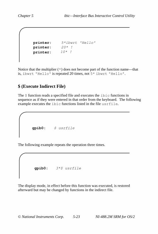
Chapter 5 ibic—Interface Bus Interactive Control Utility
© National Instruments Corp. 5-23 NI-488.2M SRM for OS/2
printer:printer: 20* !
10* !
5*ibwrt "Hello"
printer:
Notice that the multiplier (* ) does not become part of the function name—thatis, ibwrt "Hello" is repeated 20 times, not 5* ibwrt "Hello" .
$ (Execute Indirect File)
The $ function reads a specified file and executes the ibic functions insequence as if they were entered in that order from the keyboard. The followingexample executes the ibic functions listed in the file usrfile .
gpib0: $ usrfile
The following example repeats the operation three times.
gpib0: 3*$ usrfile
The display mode, in effect before this function was executed, is restoredafterward but may be changed by functions in the indirect file.
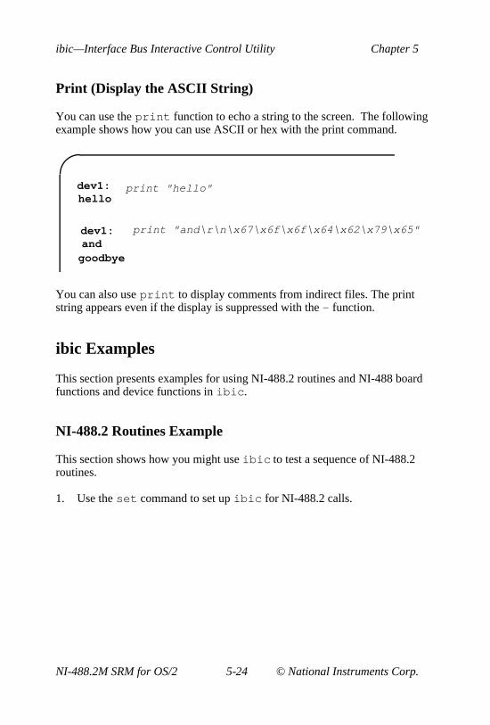
ibic—Interface Bus Interactive Control Utility Chapter 5
NI-488.2M SRM for OS/2 5-24 © National Instruments Corp.
Print (Display the ASCII String)
You can use the print function to echo a string to the screen. The followingexample shows how you can use ASCII or hex with the print command.
dev1:hello
dev1: and
goodbye
print "hello"
print "and\r\n\x67\x6f\x6f\x64\x62\x79\x65"
You can also use print to display comments from indirect files. The printstring appears even if the display is suppressed with the - function.
ibic Examples
This section presents examples for using NI-488.2 routines and NI-488 boardfunctions and device functions in ibic .
NI-488.2 Routines Example
This section shows how you might use ibic to test a sequence of NI-488.2routines.
1. Use the set command to set up ibic for NI-488.2 calls.

Chapter 5 ibic—Interface Bus Interactive Control Utility
© National Instruments Corp. 5-25 NI-488.2M SRM for OS/2
488.2 (0):
set 488.2:
2. Send the interface clear message (IFC) to all devices. IFC clears the bus.
488.2 (0):[0130] (cmpl cic atn)
SendIFC
3. Clear the device. The device is assumed to be on the GPIB bus at primaryaddress 2.
488.2 (0): DevClear 2[0138] (cmpl cic atn tacs)count: 4

ibic—Interface Bus Interactive Control Utility Chapter 5
NI-488.2M SRM for OS/2 5-26 © National Instruments Corp.
4. Write the routine, range, and trigger source information to a digitalvoltmeter.
488.2 (0): Send 2 "F3R7T3" DABend[0128] (cmpl cic tacs)count: 6
5. Trigger the device.
488.2 (0): Trigger 2[0138] (cmpl cic atn tacs)count: 4

Chapter 5 ibic—Interface Bus Interactive Control Utility
© National Instruments Corp. 5-27 NI-488.2M SRM for OS/2
6. Wait for the meter to request service (by asserting the SRQ bus line), thenread the status byte of the meter.
488.2 (0):[1138] (srqi cmpl cic atn tacs)SRQ line is asserted
488.2 (0):[0134] (cmpl cic atn lacs)Poll: 2 => 0x0040 (decimal : 64)
WaitSRQ
ReadStatusByte 2
7. Read the data from the meter.
Receive 2 20 STOPend488.2 (0):[2124] (end cmpl cic lacs)count: 200d 0a 4e 44 43 56 2d 30 • • N D C V - 030 30 2e 30 30 34 37 45 0 0 . 0 0 4 7 E2b 30 0d 0a + 0 • •
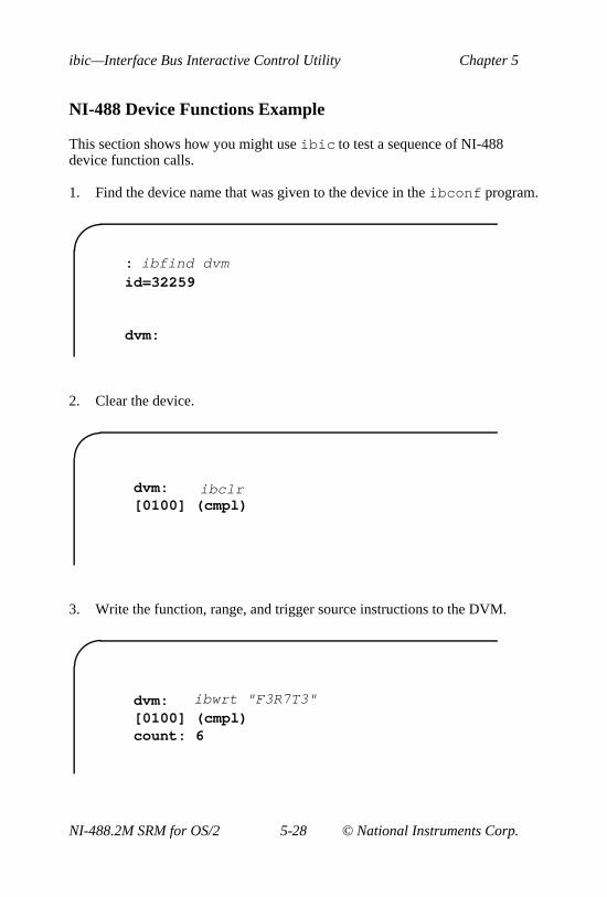
ibic—Interface Bus Interactive Control Utility Chapter 5
NI-488.2M SRM for OS/2 5-28 © National Instruments Corp.
NI-488 Device Functions Example
This section shows how you might use ibic to test a sequence of NI-488device function calls.
1. Find the device name that was given to the device in the ibconf program.
id=32259
dvm:
: ibfind dvm
2. Clear the device.
dvm:[0100] (cmpl)
ibclr
3. Write the function, range, and trigger source instructions to the DVM.
dvm:[0100] (cmpl)count: 6
ibwrt "F3R7T3"

Chapter 5 ibic—Interface Bus Interactive Control Utility
© National Instruments Corp. 5-29 NI-488.2M SRM for OS/2
4. Trigger the device.
dvm:[0100] (cmpl)
ibtrg
5. Wait for a timeout or for DVM to request service. If the current timeoutlimit is too short, use ibtmo to change it.
dvm:[0900] (rqs cmpl)
ibwait (TIMO RQS)
6. Read the serial poll status byte. This serial poll status byte varies,depending on the device used.
dvm:[0100] (cmpl)Poll: 0x40 (decimal : 64)
ibrsp

ibic—Interface Bus Interactive Control Utility Chapter 5
NI-488.2M SRM for OS/2 5-30 © National Instruments Corp.
7. Use the read command to display the data on the screen both in hex valuesand their ASCII equivalents.
dvm:[0100] (cmpl)count: 184e 44 43 56 20 30 30 30 N D C V 0 0 02e 30 30 34 37 45 2b 30 . 0 0 4 7 E + 00a 0a • •
ibrd 18
8. Terminate the ibic program.
dvm: e

Chapter 5 ibic—Interface Bus Interactive Control Utility
© National Instruments Corp. 5-31 NI-488.2M SRM for OS/2
NI-488 Board Functions Example
This section shows how you might use ibic to test a sequence of NI-488 boardfunction calls.
1. Begin by opening an interface board.
id=32006
gpib0:
: ibfind gpib0
2. Send IFC to all devices. IFC clears the bus and asserts attention (ATN) onthe bus.
gpib0:[0130] (cmpl cic atn)
ibsic
3. Turn on the remote enable signal (REN).
gpib0:[0130] (cmpl cic atn)previous value: 0
ibsre 1

ibic—Interface Bus Interactive Control Utility Chapter 5
NI-488.2M SRM for OS/2 5-32 © National Instruments Corp.
4. Set up the addressing for the device to listen and the computer to talk. Thequestion mark (?) and underscore (_) characters represent the unlisten(UNL) and untalk (UNT) commands, respectively. These are sent inibcmd to reset the bus addressing. The @ character represents the talkaddress of the GPIB board. The ! character represents the listen address ofthe device, which in this case is at GPIB primary address 1.
gpib0:[0138] (cmpl cic atn tacs)count: 4
ibcmd "?_@!"
5. Write the function, range, and trigger source instructions to the DVM. Besure an error has not occurred before proceeding.
gpib0:[0128] (cmpl cic tacs)count: 6
ibwrt "F3R7T3"

Chapter 5 ibic—Interface Bus Interactive Control Utility
© National Instruments Corp. 5-33 NI-488.2M SRM for OS/2
6. Send the group execute trigger message (GET) to trigger a measurementreading. The GET message is represented by the hex value 8.
gpib0:[0138] (cmpl cic atn tacs)count: 1
ibcmd "\x08"
7. Wait for the DVM to set SRQ or wait for a timeout. If the current timeoutlimit is too short, use ibtmo to change it.
gpib0:[1138] (srqi cmpl cic atn tacs)
ibwait (TIMO SRQI)
8. Set up the device for a serial poll. The question mark (?) and underscore( _ ) characters represent the unlisten (UNL) and untalk (UNT) characters,respectively, and reset the bus addressing. The underscore ( _ ) representsthe listen address of the Controller. The hex value 18 represents the serialpoll enable function, while A represents the talk address of the device.
gpib0:[1174] (srqi cmpl rem cic atn lacs)count: 5
ibcmd "?_ \x18A"
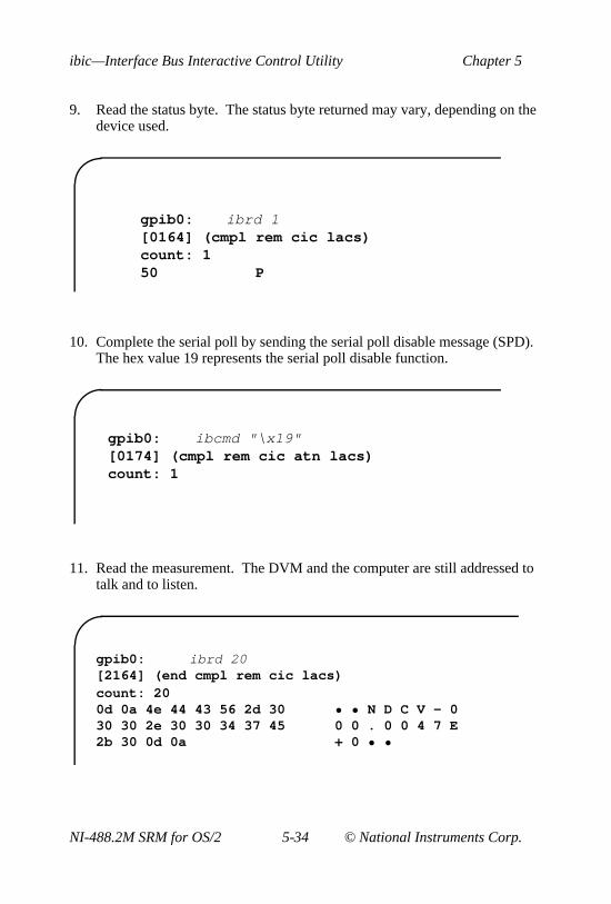
ibic—Interface Bus Interactive Control Utility Chapter 5
NI-488.2M SRM for OS/2 5-34 © National Instruments Corp.
9. Read the status byte. The status byte returned may vary, depending on thedevice used.
gpib0:[0164] (cmpl rem cic lacs)count: 150 P
ibrd 1
10. Complete the serial poll by sending the serial poll disable message (SPD).The hex value 19 represents the serial poll disable function.
gpib0:[0174] (cmpl rem cic atn lacs)count: 1
ibcmd "\x19"
11. Read the measurement. The DVM and the computer are still addressed totalk and to listen.
gpib0:[2164] (end cmpl rem cic lacs)count: 200d 0a 4e 44 43 56 2d 30 • • N D C V - 030 30 2e 30 30 34 37 45 0 0 . 0 0 4 7 E2b 30 0d 0a + 0 • •
ibrd 20

Chapter 5 ibic—Interface Bus Interactive Control Utility
© National Instruments Corp. 5-35 NI-488.2M SRM for OS/2
12. Terminate the ibic program.
gpib0: e

© National Instruments Corp. 6-1 NI-488.2M SRM for OS/2
Chapter 6GPIB Programming Techniques
This chapter discusses the following GPIB topics: data transfer terminationmethods, waiting for GPIB conditions, device-level calls and bus management,serial polling and SRQ servicing, and parallel polling.
Termination of Data Transfers
GPIB data transfers are terminated either when the GPIB EOI line is assertedwith the last byte of a transfer or when a preconfigured end-of-string (EOS)character is transmitted. By default, the NI-488.2M driver asserts EOI with thelast byte of writes and the EOS modes are disabled.
You can use the ibeot function to enable the end of transmission (EOT)mode. If EOT mode is enabled, the NI-488.2M driver asserts the GPIB EOIline when the last byte of a write is sent out on the GPIB. If it is disabled, theEOI line is not asserted with the last byte of a write.
You can use the ibeos function to enable/disable or configure the EOS modes.EOS mode configuration includes the following information:
• A 7-bit or 8-bit EOS byte.
• The EOS comparison method, which indicates whether the EOS byte has 7or 8 significant bits. For a 7-bit EOS byte, the high bit of the EOS byte isignored.
• The EOS write method. If the EOS write method is enabled, theNI-488.2M driver automatically asserts the GPIB EOI line when the EOSbyte is written to the GPIB. If the buffer passed into an ibwrt callcontains five occurrences of the EOS byte, the EOI line is asserted as eachof the five EOS bytes is written to the GPIB. If an ibwrt buffer does notcontain an occurrence of the EOS byte, the EOI line is not asserted (unlessthe EOT mode is enabled, in which case the EOI line is asserted with thelast byte of the write).

GPIB Programming Techniques Chapter 6
NI-488.2M SRM for OS/2 6-2 © National Instruments Corp.
• The EOS read method. If the EOS read method is enabled, theNI-488.2M driver terminates ibrd calls when the EOS byte is detected onthe GPIB or when the GPIB EOI line is asserted or when the specifiedcount has been reached. If the EOS read method is disabled, ibrd callsterminate only when the GPIB EOI line is asserted or the specified counthas been read.
You can use the ibconfig function to determine whether the GPIBEOI line was asserted when the EOS byte was read in. Use theIbcEndBitIsNormal option to configure the software to report onlythe END bit in ibsta when the GPIB EOI line is asserted. By default, the NI-488.2M driver reports END in ibsta when either the EOS byte is read in orthe EOI line is asserted during a read.
Waiting for GPIB Conditions
You can use the ibwait function to obtain the current ibsta value or tosuspend your application until a specified condition occurs on the GPIB. If youuse ibwait with a parameter of 0, it immediately updates ibsta and returns.If you want to use ibwait to wait for one or more events to occur, then pass await mask to the function. The wait mask should always include the TIMOevent; otherwise, your application is suspended indefinitely until one of thewait mask events occurs.
Device-Level Calls and Bus Management
The NI-488 device-level calls are designed to perform all of the GPIBmanagement for your application program. However, the NI-488.2M driver canhandle bus management only when the GPIB interface board is CIC. Only theCIC is able to send command bytes to the devices on the bus in order to performdevice addressing or other bus management activities. Use one of the followingmethods to make your GPIB board the CIC:
• If your GPIB board is configured as the System Controller (default), itautomatically makes itself the CIC by asserting the IFC line the first timeyou make a device-level call.

Chapter 6 GPIB Programming Techniques
© National Instruments Corp. 6-3 NI-488.2M SRM for OS/2
• If your setup includes more than one Controller or if your GPIB interfaceboard is not configured as the System Controller, use the CIC protocolmethod. To use the protocol, issue the ibconfig function or use theibconf configuration utility to activate the CIC protocol. If the interfaceboard is not CIC and you make a device-level call with the CIC protocolenabled, the following sequence occurs:
1. The GPIB interface board asserts the SRQ line.
2. The current CIC serial polls the board.
3. The interface board returns a response byte of hex 42.
4. The current CIC passes control to the GPIB board.
If the current CIC does not pass control, the NI-488.2M driver returns theECIC error code to your application. This error can occur if the current CICdoes not understand the CIC protocol. If this happens, you could send adevice-specific command requesting control for the GPIB board, then youcould use a board-level ibwait command to wait for CIC.
Serial Polling
You can use serial polling to obtain specific information from GPIB deviceswhen they request service. When the GPIB SRQ line is asserted, it signals theController that a service request is pending. The Controller must then determinewhich device asserted the SRQ line and respond accordingly. The most commonmethod for SRQ detection and servicing is the serial poll. This section describeshow you can set up your application to detect and respond to service requestsfrom GPIB devices.
Service Requests from IEEE 488 Devices
IEEE 488 devices request service from the GPIB Controller by asserting theGPIB SRQ line. When the Controller acknowledges the SRQ, it serial pollseach device on the bus in order to determine which device requested service.Any device requesting service returns a status byte with bit 6 set and thenunasserts the SRQ line. Devices not requesting service return a status byte withbit 6 cleared. Manufacturers of IEEE 488 devices use lower order bits tocommunicate the reason for the service request or to summarize the state of thedevice.

GPIB Programming Techniques Chapter 6
NI-488.2M SRM for OS/2 6-4 © National Instruments Corp.
Service Requests from IEEE 488.2 Devices
The IEEE 488.2 standard refined the bit assignments in the status byte. Inaddition to setting bit 6 when requesting service, IEEE 488.2 devices also usetwo other bits to specify their status. Bit 4, the Message Available bit (MAV),is set when the device is ready to send previously queried data.Bit 5, the Event Status bit (ESB), is set if one or more of the enabledIEEE 488.2 events occurs. These events include Power-On, User Request,Command Error, Execution Error, Device Dependent Error, Query Error,Request Control, and Operation Complete. The device can assert SRQ whenESB or MAV is set or when a manufacturer-defined condition occurs.
Automatic Serial Polling
You can enable automatic serial polling if you want your application to conducta serial poll automatically any time the SRQ line is asserted. The autopollingprocedure occurs as follows.
1. Use the configuration utility, ibconf , or the configuration function,ibconfig with option IbcAUTOPOLL. (Autopolling is enabled bydefault.)
2. When the SRQ line is asserted, the driver automatically serial polls thedevices.
3. Each positive serial poll response (bit 6 or hex 40 is set) is stored in a queueassociated with the device that sent it. If the poll has a positive response,the RQS bit of the device status word, ibsta , is set.
4. The polling continues until SRQ is unasserted or an error condition isdetected.
5. The RQS bit of the device status word remains set as long as the autopollresponse queue is not empty. The RQS bit is cleared when the autopollresponse queue becomes empty.
6. Use the ibrsp function to empty the queue. ibrsp returns the firstqueued response. Other responses are read in first-in-first-out (FIFO)fashion. If the RQS bit of the status word is not set when ibrsp is called,a serial poll is conducted and returns whatever response is received. Youshould empty the queue as soon as an automatic serial poll occurs, becauseautopolling may not continue if the queue is full.

Chapter 6 GPIB Programming Techniques
© National Instruments Corp. 6-5 NI-488.2M SRM for OS/2
7. If the RQS bit of the status word is still set after ibrsp is called, theresponse byte queue contains at least one more response byte. If thishappens, you should continue to call ibrsp until RQS is cleared.
If no device responds positively to the serial poll or if SRQ remains in effectbecause of a faulty instrument or cable, a GPIB system error occurs. In thiscase, the ESRQ error is reported to you if and when you issue an ibwait callwith the RQS bit included in the wait mask. Aside from the difficulty causedby ESRQ in waiting for RQS, the error has no detrimental effects on otherGPIB operations.
Autopolling and the Stuck SRQ State
If autopolling is enabled and the GPIB interface board detects an SRQ, all opendevices connected to that board are serial polled by the driver. The serial pollcontinues until either SRQ unasserts or all the devices have been polled.
If the driver serial polls all devices and the SRQ line is still asserted, a stuckSRQ state is in effect. If this happens during an ibwait for RQS, the driverreports the ESRQ error. If the stuck SRQ state happens, no further polls areattempted until either an ibwait for RQS or an ibrsp for the device whoseserial poll queue is full is made. When either ibwait or ibrsp for the devicewhose serial poll is full is issued, the stuck SRQ state is terminated and a newset of serial polls is attempted.
Autopolling and Interrupts
If autopolling and interrupts are both enabled, the NI-488.2M software canperform autopolling after any device-level NI-488 call as long as no GPIB iscurrently I/O in progress. This means that an automatic serial poll can occureven when your application is not making any calls to the NI-488.2M software.Autopolling can also occur when a device-level ibwait for RQS is inprogress. Autopolling is disallowed whenever an application makes a board-level NI-488 function or any NI-488.2 routine or when the stuck SRQ (ESRQ)condition occurs.
If autopolling is enabled and interrupts are disabled, you can use autopollingonly during a device-level ibwait for RQS or immediately after a device-levelNI-488 function is completed and before control is returned to the applicationprogram.

GPIB Programming Techniques Chapter 6
NI-488.2M SRM for OS/2 6-6 © National Instruments Corp.
SRQ and Serial Polling with NI-488 Device Functions
You can use the device-level NI-488 function ibrsp to conduct a serial poll.ibrsp conducts a single serial poll and returns the serial poll response byte tothe application program. If automatic serial polling is enabled, the applicationprogram can use ibwait to suspend program execution until RQS appears inthe status word, ibsta . The program can then call ibrsp to obtain the serialpoll response byte.
The following example illustrates the use of the ibwait and ibrsp functionsin a typical SRQ servicing situation when automatic serial polling is enabled.
#include “decl.h”
char GetSerialPollResponse ( int DeviceHandle ){
char SerialPollResponse = 0;
ibwait ( DeviceHandle, TIMO | RQS );
if ( ibsta & RQS ) {printf ( “Device asserted SRQ.\n” );/* Use ibrsp to retrieve the serial poll
response. */ibrsp ( DeviceHandle, &SerialPollResponse );
}return SerialPollResponse;
}
SRQ and Serial Polling with NI-488.2 Routines
The NI-488.2M software includes a set of NI-488.2 routines that you can use toconduct SRQ servicing and serial polling. Routines pertinent to SRQ servicingand serial polling are AllSpoll , FindRQS , ReadStatusByte , TestSRQ ,and WaitSRQ.
AllSpoll can serial poll multiple devices with a single call. It places thestatus bytes from each polled instrument into a predefined array, then you mustcheck the RQS bit of each status byte to determine whether that devicerequested service.

Chapter 6 GPIB Programming Techniques
© National Instruments Corp. 6-7 NI-488.2M SRM for OS/2
ReadStatusByte is similar to AllSpoll , except that it only serial polls asingle device. It is also analogous to the device-level NI-488 ibrsp function.
FindRQS serial polls a list of devices until it finds a device that is requestingservice or until it has polled all the devices on the list. The routine returns theindex and status byte value of the device requesting service.
TestSRQ determines whether the SRQ line is asserted or unasserted, and itreturns to the program immediately.
WaitSRQ is similar to TestSRQ, except that WaitSRQ suspends theapplication program until either SRQ is asserted or the timeout period isexceeded.
The following examples use NI-488.2 routines to detect SRQ, then determinewhich device requested service. In these examples, three devices are present onthe GPIB at addresses 3, 4, and 5, and the GPIB interface is designated as busindex 0. The first example uses FindRQS to determine which device isrequesting service, and the second example uses AllSpoll to serial poll allthree devices. Both examples use WaitSRQ to wait for the GPIB SRQ line tobe asserted.
Note: Automatic serial polling is not used in these examples because youcannot use it with NI-488.2 routines.
Example 1
This example illustrates the use of FindRQS to determine which device isrequesting service.
void GetASerialPollResponse ( char *DevicePad,char *DeviceResponse )
{char SerialPollResponse = 0;int WaitResult;Addr4882_t Addrlist[4] = {3,4,5,NOADDR};
WaitSRQ (0, &WaitResult);
if (WaitResult) {printf (“SRQ is asserted.\n”);

GPIB Programming Techniques Chapter 6
NI-488.2M SRM for OS/2 6-8 © National Instruments Corp.
/* Use FindRQS to find a device that requested service. */
FindRQS ( 0, AddrList, &SerialPollResponse );if (!(ibsta & ERR)) {
printf (“Device at pad %x returned byte %x.\n”, AddrList[ibcnt], (int)SerialPollResponse);
*DevicePad = AddrList[ibcnt];*DeviceResponse = SerialPollResponse;
}}
return;}
Example 2
This example illustrates the use of AllSpoll to serial poll three devices.
void GetAllSerialPollResponses ( Addr4882_t AddrList[],short ResponseList[] ){
int WaitResult;
WaitSRQ (0, &WaitResult);
if ( WaitResult ) {printf ( “SRQ is asserted.\n” );
/* Use Allspoll to serial poll all the devices at once.*/
AllSpoll ( 0, AddrList, ResponseList );if (!(ibsta & ERR)) {
for ( i = 0; AddrList[i] != NOADDR; i++ ) {printf(“Device at pad %x returned byte %x.\n”,
AddrList[i], ResponseList[i] );}
}}
return;}

Chapter 6 GPIB Programming Techniques
© National Instruments Corp. 6-9 NI-488.2M SRM for OS/2
Parallel Polling
Although parallel polling is not widely used, it is a useful method for obtainingthe status of more than one device at the same time. The advantage of parallelpolling is that a single parallel poll can easily check up to eight individualdevices at once. In comparison, eight separate serial polls would be required tocheck eight devices for their serial poll response bytes. The value of theindividual status bit (ist ) determines the parallel poll response.
Implementing a Parallel Poll
You can implement parallel polling with either NI-488 functions or NI-488.2Mroutines. If you use NI-488.2M routines to execute parallel polls, you do notneed extensive knowledge of the parallel polling messages. However, youshould use the NI-488.2M functions for parallel polling when the GPIB board isnot the Controller and must configure itself for a parallel poll and set its ownindividual status bit (ist ).
Parallel Polling with NI-488.2 Routines
Follow these steps to implement parallel polling using NI-488.2 routines. Eachstep contains example code.
1. Configure the device for parallel polling using the PPollConfigroutine, unless the device can configure itself for parallel polling. Thefollowing example configures a device at address 3 to assert data line 5(DIO5) when its ist value is 1.
#include "decl.h"char response;Addr4882_t AddressList[2];
/* The following command clears the GPIB. */
SendIFC(0);
/* The value of sense is compared with the ist bit ofthe device and determines whether the data line isto be asserted or unasserted. */
PPollConfig(0,3,5,1);

GPIB Programming Techniques Chapter 6
NI-488.2M SRM for OS/2 6-10 © National Instruments Corp.
2. Conduct the parallel poll using PPoll , store the response, and check theresponse for a certain value. In the following example, because DIO5 isasserted by the device if ist = 1, the program checks bit 4 (hex 10) in theresponse to determine the value of ist .
/* The second step performs the parallel poll and stores the response in response. */
PPoll(0, &response);
/* If response has bit 4 (hex 10) set, the ist bit of the device at that time is equal to 1. If it does not appear, the ist bit is equal to 0. Check the bit in the following statement. */
if (response & 0x10) {printf("The ist equals 1.\n");
}else {
printf("The ist equals 0.\n");}
3. Unconfigure the device for parallel polling using the PPollUnconfigroutine.
/* The third step disables parallel polling for device 3. Notice that the NOADDR constant must appear at the end of the array to signal the end of the address list. If NOADDR is the only value in the array, ALL devices are sent the parallel poll disable message. */
AddressList[0] = 3;AddressList[1] = NOADDR;PPollUnconfig(0, AddressList);
Parallel Polling with NI-488 Functions
Follow these steps to implement parallel polling using NI-488 functions. Eachstep contains example code.
1. Configure the device for parallel polling using the ibppc function, unlessthe device can configure itself for parallel polling.

Chapter 6 GPIB Programming Techniques
© National Instruments Corp. 6-11 NI-488.2M SRM for OS/2
ibppc requires an 8-bit value to designate the data line number, the istsense, and whether the function configures or unconfigures the device forthe parallel poll. The bit pattern is as follows:
0 1 1 E S D2 D1 D0
E is 1 to disable parallel polling and 0 to enable parallel polling for thatparticular device.
S is 1 if the device is to assert the assigned data line when ist = 1, and Sis 0 if the device is to assert the assigned data line whenist = 0.
D2 through D0 determine the number of the assigned data line. Thephysical line number is the binary line number plus one. For example,DIO3 has a binary bit pattern of 010.
The following example code configures a device for parallel polling usingNI-488 functions. The device asserts DIO7 if its ist = 0.
In this example, the ibdev command is used to open a generic device thathas the desired characteristics. The device has a primary address of 3, nosecondary address, a timeout of 3 s, EOS characters disabled, and assertsEOI with the last byte of a write operation.
#include "decl.h"char ppr;
dev = ibdev(0,3,0,T3s,1,0);
/* The following call configures the device torespond to the poll on DIO7 and to assert the linein the case when its ist is 0. Pass the binarybit pattern, 0110 0110 or hex 66, to ibppc.*/
ibppc(dev, 0x66);
If the GPIB interface board configures itself for a parallel poll, you shouldstill use the ibppc function. Pass the board index or a board unitdescriptor value as the first argument in ibppc . In addition, if theindividual status bit (ist ) of the board needs to be changed, use theibist function. In the following example, the GPIB board is to configureitself to participate in a parallel poll. It asserts DIO5 when ist = 1 if aparallel poll is conducted.
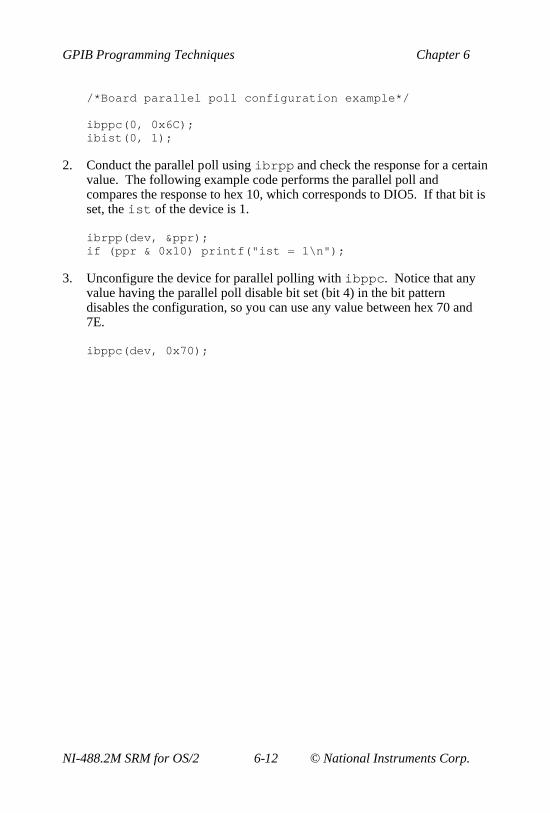
GPIB Programming Techniques Chapter 6
NI-488.2M SRM for OS/2 6-12 © National Instruments Corp.
/*Board parallel poll configuration example*/
ibppc(0, 0x6C);ibist(0, 1);
2. Conduct the parallel poll using ibrpp and check the response for a certainvalue. The following example code performs the parallel poll andcompares the response to hex 10, which corresponds to DIO5. If that bit isset, the ist of the device is 1.
ibrpp(dev, &ppr);if (ppr & 0x10) printf("ist = 1\n");
3. Unconfigure the device for parallel polling with ibppc . Notice that anyvalue having the parallel poll disable bit set (bit 4) in the bit patterndisables the configuration, so you can use any value between hex 70 and7E.
ibppc(dev, 0x70);

© National Instruments Corp. 7-1 NI-488.2M SRM for OS/2
Chapter 7ibconf—Interface Bus ConfigurationUtility
This chapter contains a description of ibconf , the software configurationprogram you can use to configure the NI-488.2M software.
Overview
The ibconf utility is a screen-oriented, interactive program you can use toview or modify the configuration parameters of your GPIB interface boards andthe GPIB devices connected to them.
The ibconf utility can read in and display configuration parameters for thedriver file on disk, the driver resident in memory, or the configuration data file,depending on which you select. You can then save the changes to any or all ofthese files.
Instead of using ibconf , you can configure your driver dynamically by usingthe ibconfig function to alter any board or device characteristic while yourprogram is running. If you use dynamic configuration, you do not need to runibconf before you start your application. Also, you can run your applicationon any computer with the appropriate NI-488.2M software regardless of itsconfiguration, because the application configures the driver as necessary.
Note: Dynamic configuration is the preferred method of GPIB applicationdevelopment.
Starting ibconf
The ibconf utility is included on the distribution disk with yourNI-488.2M software. After installation, ibconf resides in your GPIBdirectory. To run ibconf , change to your GPIB directory and enter thefollowing command:
ibconf [-h[elp]] [-c] [-m] [-e]

ibconf—Interface Bus Configuration Utility Chapter 7
NI-488.2M SRM for OS/2 7-2 © National Instruments Corp.
where -h or -help causes the command format to be printed to the screen; -cenables color support (default for color monitors); -m sets monochromeoverride; and -e enables expert mode, disabling ibconf warning messages.
Levels of ibconf
The ibconf utility operates at the following four levels:
• Input Selection level—determines which configuration file ibconf reads.
• Map level—depicts the device connections as defined in the driver.
• Description level—consists of screens describing the individual boards anddevices that make up the system.
• Output Selection level—determines which configuration files are to beupdated.
The four levels are described in detail in the following sections.
Input Selection Level
Figure 7-1 shows the screen of the input selection level in ibconf .
Figure 7-1. Input Selection Level of ibconf

Chapter 7 ibconf—Interface Bus Configuration Utility
© National Instruments Corp. 7-3 NI-488.2M SRM for OS/2
In the input selection level, you can select a source file that containsconfiguration data. When you select a source configuration file, ibconfobtains configuration settings from that source file. The settings are displayedand you can then edit them.
The three types of configuration files are the driver residing on your hard disk,the memory-resident driver, and the data file.
• Driver—an NI-488.2M driver file for OS/2, such as gpib.sys , that youcopy from the distribution disk to your hard disk. Changes to a driver filedo not affect your application until the system is restarted.
Caution: Do not modify the master copy of gpib.sys on thedistribution disk. Make sure your distribution disk is writeprotected.
• Memory-resident driver—the NI-488.2M driver for OS/2 that isloaded and resident in memory after system startup. Changes in thememory-resident driver take effect for a given board or device only after allcurrent processes have closed that board or device and a new open isperformed.
Note: You cannot change device names, board interrupt levels, or the Usethis GPIB Interface setting state in the memory-residentdriver. To change these settings, you must change them by usingibconf (in the driver residing on your hard disk), then reboot thesystem.
• Data file—a binary file that stores configuration data. To load a data file tothe driver or the memory-resident driver, run ibconf and select the datafile as the source.
After you select a source configuration file, continue to the next level, the maplevel. If you want to read a configuration from another source file, you must exitand restart ibconf .

ibconf—Interface Bus Configuration Utility Chapter 7
NI-488.2M SRM for OS/2 7-4 © National Instruments Corp.
Map Level
Figure 7-2 shows the map level of ibconf .
Figure 7-2. Map Level of ibconf
The map-level screen of ibconf displays the names of all devices controlled bythe driver. It also indicates which devices, if any, are accessed through eachinterface board. You can move around the map by using the cursor control keys.For your convenience, cursor control keys and function keys are defined at thebottom of your computer screen.
The following options are available at the map level:
• Device map of the boards
• Help
• Rename
• (Dis)connect
• Edit
• Exit
The following sections describe the options available in the map level ofibconf .

Chapter 7 ibconf—Interface Bus Configuration Utility
© National Instruments Corp. 7-5 NI-488.2M SRM for OS/2
Device Map of the Boards
Use <PageUp> or <PageDown> to toggle between the display maps for thedifferent GPIB interface boards. These boards are referred to as access boards.The maps show which devices are assigned to each board. By default, an equalnumber of devices are attached to each GPIB interface board.
Help
Use <F1> to access the comprehensive, online help feature of ibconf . Thehelp information describes the functions and common terms associated with themap level of ibconf .
Rename
Use <F4> to rename a device. Move to the device you want to rename by usingthe cursor control keys. Press <F4>, then enter the new name of the device. Youmay use up to seven letters to name your device, and you may use uppercase orlowercase letters. The following restrictions apply when naming a device:
• Extensions (.xxx) are not allowed.
• As specified by OS/2, the device name cannot have the following invalidcharacters (ASCII characters less than hex 21):
. " / \ [ ] :| < > + = ; ,
• Do not use the reserved names con or nul for your device.
• Do not give GPIB device names the same names as files, directories, orsubdirectories. If you name a device pltr and your file system containsthe file pltr.dat or a subdirectory pltr , a conflict results.
• You cannot rename the access boards gpib0 , gpib1 , gpib2 , and gpib3 .
If you have pressed <F4 > and have then decided not to rename the device, press<F4> again to abort the function.

ibconf—Interface Bus Configuration Utility Chapter 7
NI-488.2M SRM for OS/2 7-6 © National Instruments Corp.
(Dis)connect
Use <F5> to connect or disconnect a device to or from a particular access board.Move the cursor to the device that is to be connected or disconnected by usingthe cursor control keys and then pressing <F5>.
Edit
Use <F8> to edit or examine the characteristics of a particular board or device.Move to the board or device that you want to edit by using the cursor controlkeys and pressing <F8>. This places you in the description level of ibconf andlists all the characteristics for the particular board or device that you want to edit.To exit edit, use <F9> or <Esc>.
Exit
Use <F9> or <Esc> to exit ibconf . If you have made changes and havepressed <F9> to exit, ibconf displays Save configuration? . Type y(yes) to save the changes or n (no) to discard the changes. For moreinformation, refer to the Exiting ibconf section, which is located later in thischapter.
If you have pressed <F9> and have then decided not to exit, press <F9> again toabort the function.

Chapter 7 ibconf—Interface Bus Configuration Utility
© National Instruments Corp. 7-7 NI-488.2M SRM for OS/2
Description Level
The description-level screens of ibconf display current values, suchas addressing and timeout information, for device or board settings. See Figure7-3.
Figure 7-3. Description Level of ibconf
You can access the description-level screens from the map level of ibconf byselecting a board or device and pressing <F8>. You can use the <Up>, <Down>,<PageUp>, and <PageDown> cursor keys to select a characteristic. For yourconvenience, cursor control keys and function keys are defined at the bottom ofyour computer screen.
Selecting the configuration settings for each device and board customizes thecommunications and other options to be used with that board or device. Thesesettings are the characteristics used by the access board when device functionsare used to program the device or when board functions are used to program theboard.
The following options are available at the description level:
• Change Characteristics
• Next Board/Device

ibconf—Interface Bus Configuration Utility Chapter 7
NI-488.2M SRM for OS/2 7-8 © National Instruments Corp.
• Help
• Reset Value
• Return to Map
The following sections describe the options available in the description level ofibconf .
Change Characteristics
To change a specific characteristic of a device or a board, first move your cursorto the characteristic. If the double arrow symbol appears to the left of the inputfield, use the left/right arrow keys to select between different options. If ablinking cursor appears in the field, input the new value directly from thekeyboard. Instructions on the right half of the screen inform you about theoptions for the characteristic.
Next Board/Device
If you are viewing the characteristics of a board, use <Ctrl-PageUp> and <Ctrl-PageDown> to move to the characteristics screen for the previous or next board.If you are viewing the characteristics of a device, use <Ctrl-PageUp> and <Ctrl-PageDown> to move to the characteristics screen for the previous or next device.
Help
Use <F1> to access the comprehensive, online help feature of ibconf . Thehelp information describes the functions and common terms associated with thedescription level of ibconf .
Reset Value
Use <F6> to reset the current characteristic to the value it contained when it waslast modified.
Return to Map
Use <F9> or <Esc> at the description level to return to the map level ofibconf .

Chapter 7 ibconf—Interface Bus Configuration Utility
© National Instruments Corp. 7-9 NI-488.2M SRM for OS/2
Output Selection Level
Figure 7-4 shows the output selection level of ibconf.
Figure 7-4. Output Selection Level of ibconf
In the output selection level, you can select the configuration files that should beupdated by ibconf . To create or update a data file, respond yes to copychanges to the data file. The data file confil.cf (the default name) is thencreated or opened and the new configuration is stored into it.
If you select yes to copy changes to the memory resident driver, ibconfupdates the driver that is currently resident in memory. If you select yes tocopy changes to drivers on disk, ibconf updates the driver file on disk.
Board and Device Configuration Options
To view detailed information about each characteristic, position the cursor in thefield for that characteristic. For information on characteristics specific to a givendriver, check the getting-started manual that came with your interface board.The following paragraphs describe the options available in ibconf for the NI-488.2M software for OS/2.

ibconf—Interface Bus Configuration Utility Chapter 7
NI-488.2M SRM for OS/2 7-10 © National Instruments Corp.
Primary GPIB Address
All devices and boards must be assigned a unique primary address in the rangehex 00 to hex 1E (0 to 30 decimal). The default primary address of all GPIBboards is 0.
The GPIB primary address of any device is set within the device, either withhardware switches or a software program. The address set within the devicemust correspond to the address in the memory-resident driver. In the NI-488.2Mdriver for OS/2, the default primary addresses of dev1 through dev32 are 1through 32, respectively. Refer to the device documentation for instructionsabout setting the device address. GPIB boards do not have hardware switches toselect the GPIB address.
The primary GPIB address is used to compute the talk and listen addresses ofdevices and boards. The NI-488.2M driver automatically forms a listen addressby adding hex 20 to the primary address and a talk address by adding hex 40 tothe primary address. For example, a primary address of hex 10 has a listenaddress of hex 30 and a talk address of hex 50.
Secondary GPIB Address
Any device or board using extended addressing must be assigned a secondaryaddress in the range hex 60 to hex 7E (96 to 126 decimal), or the option NONEmay be selected to disable secondary addressing.
As with primary addressing, the secondary GPIB address of a device is set withinthat device, either with hardware switches or a software program. The addressset within the device must correspond to the address in the memory-residentdriver. Refer to the device documentation for instructions about secondaryaddressing. The default setting for this characteristic is NONE for all boards anddevices.
Timeout Setting
The timeout value is the approximate length of time that GPIB functions wait fordata to be transferred or commands to be sent. It is also the length of time thatthe ibwait function waits for an event before returning, if the TIMO bit is setin the event mask. For example, if the SRQI bit and TIMO bit in the event maskare passed to the ibwait function and no SRQ is detected, the functiontimeouts after the duration given by the timeout setting value. The default optionfor this characteristic is 10 s.

Chapter 7 ibconf—Interface Bus Configuration Utility
© National Instruments Corp. 7-11 NI-488.2M SRM for OS/2
Terminate Read on EOS
Some devices send an EOS byte signaling the last byte of a data message.A yes response in this field causes the GPIB board to terminate a read operationwhen it receives the EOS byte. The default option for this characteristic is no .
Set EOI with EOS on Writes
A yes response in this field causes the GPIB board to assert the EOI line whenthe EOS byte is detected on a write operation. The default option for thischaracteristic is no .
Type of Compare on EOS
This field specifies the type of comparison to be made with the EOS byte. Youmay state whether all eight bits are to be compared or just the seven leastsignificant bits (ASCII or ISO [International Standards Organization] format).The default option for this characteristic is 7-bit .
Note: This field is valid only if a yes response was given for either the SetEOI with EOS on Write field or the Terminate Read on EOS field.
EOS Byte
Some devices can be programmed to terminate a read operation when a selectedcharacter is detected. A linefeed character (hex 0A) is a common EOS byte.The default option for this characteristic is 00H.
Note: The driver does not automatically append an EOS byte to the end ofdata strings on write operations. You must explicitly include this bytein your data string. The EOS byte designation informs the driver ofits value so that I/O can terminate correctly.

ibconf—Interface Bus Configuration Utility Chapter 7
NI-488.2M SRM for OS/2 7-12 © National Instruments Corp.
Send EOI at End of Write
Some devices, as Listeners, require that the Talker terminate a data message byasserting the EOI line with the last byte. A yes response causes the GPIB boardto assert the EOI line on the last data byte. The default option for thischaracteristic is yes .
GPIB-Specific Errors
Boards and devices have a switch that specifies whether the NI-488.2M driverreturns OS/2 device errors or GPIB device errors when API IOCtl functions areused. A no response causes the OS/2 API functions (except the status queryfunction) to return OS/2 device errors. If this option is set to yes , GPIB-specificerrors are returned on all API IOCtl functions. The default option for thischaracteristic is yes.
System Controller (Board Characteristic Only)
This field appears on the board characteristics screen only. The SystemController in a GPIB system is the device that maintains ultimate control overthe bus. In some situations, such as a network of computers linked by the GPIB,another device may be System Controller and the GPIB board should bedesignated as not System Controller. A no response would designate notSystem Controller and a yes response would designate System Controllercapability. The GPIB board is usually designated as System Controller. Thedefault option for this characteristic is yes .
Note: You should not have more than one designated System Controller inany GPIB system.
Assert REN when SC (Board Characteristic Only)
A yes response to this field causes Remote Enable (REN) to be assertedautomatically whenever the board is placed online, if that the board has SystemController capability. If you give a no response, an explicit call to ibsre isrequired to assert REN. The default option for this characteristic is no.

Chapter 7 ibconf—Interface Bus Configuration Utility
© National Instruments Corp. 7-13 NI-488.2M SRM for OS/2
Enable Auto Serial Polling (Board Characteristic Only)
This option enables or disables automatic serial polls of devices when the GPIBService Request (SRQ) line is asserted. Positive poll responses are storedfollowing the polls and can be read with the ibrsp device function. Normally,this feature does not conflict with devices that conform to the IEEE 488 standard.If there is a conflict with a device, a no response for this field disables thisfeature. The default option for this characteristic is yes .
Enable CIC Protocol (Board Characteristic Only)
If a device-level NI-488 call is made after control has been passed to anotherdevice, enabling this protocol causes the board to assert SRQ with a Serial Pollstatus byte of hex 42. The current Controller must recognize that the boardwants to regain control. If the current Controller passes control back to theboard, the device call proceeds as intended. If control is not passed within thetimeout period, the ECIC error is returned. If the CIC protocol is disabled, ECICis returned immediately if a device call is made after control has been passed.The default option for this characteristic is no.
Bus Timing (Board Characteristic Only)
This field specifies the T1 delay of the source handshake capability for the board.This delay determines the minimum amount of time, after the data is placed onthe bus, that the board may assert DAV during a write or command operation. Ifthe total length of the GPIB cable length in the system is less than 15 m, thevalue of 350 ns is appropriate. Other factors might affect the choice of the T1delay, although they are unlikely to affect your system setup. Refer to the IEEE488.1 standard, Section 5.2, for more information about these other factors. Thedefault for this option is 500 ns.
Parallel Poll Duration (Board Characteristic Only)
This field specifies the length of time the driver waits when conducting a parallelpoll. For a normal bus configuration (the Controller and devices on the samebus), use the default duration of 2 µs. If you are using a GPIB bus extender intransparent parallel poll mode, you should increase the poll duration to 10 µs sothat the bus extender can operate transparently to your applications.

ibconf—Interface Bus Configuration Utility Chapter 7
NI-488.2M SRM for OS/2 7-14 © National Instruments Corp.
Use This GPIB Interface (Board Characteristic Only)
If you do not want the driver to try to access a board at the selected base address(because you do not have a board in the system), select no for this option. Whenthis field is set to no , the driver returns the EDVR error as soon as a programtries to access the board. By default, access board gpib0 is enabled, andgpib1 , gpib2 , and gpib3 are disabled.
Base I/O Address (Board Characteristic Only)
This field specifies the I/O address of the GPIB board. It must be set to the samevalue as the base I/O address setting for the GPIB board. Setting the base I/Oaddress level is explained in the getting-started manual that you received withyour GPIB interface board.
Note: On Micro Channel systems, this field is Read Only and you canchange the I/O address only by booting the reference diskette.
DMA Channel (Board Characteristic Only)
This field specifies the DMA channel used by the GPIB board. It must be set tothe same value as the DMA channel (arbitration level for Micro Channelsystems) setting for the GPIB board. Setting the DMA channel is explained inthe getting-started manual that you received with your GPIB interface board.
Note: On Micro Channel systems, you can change the DMA channel onlyby booting the reference diskette. However, you can enable or disablethe use of DMA with the ibconf utility .

Chapter 7 ibconf—Interface Bus Configuration Utility
© National Instruments Corp. 7-15 NI-488.2M SRM for OS/2
Interrupt Jumper Setting (Board Characteristic Only)
This field specifies the interrupt line used by the GPIB board. It must be set tothe same value as the interrupt level setting for the GPIB board. Setting theinterrupt level is explained in the getting-started manual that you received withyour GPIB board.
Note: On Micro Channel systems, you can change the interrupt level only bybooting the reference diskette. However, you can enable or disable theuse of interrupts with the ibconf utility.
DMA Transfer Mode (Board Characteristic Only)
This field specifies the DMA transfer mode of the GPIB board. Nearly all PC-compatible computers can use Demand Mode DMA, which is the fastest DMAmode. Certain newer machines, however, cannot use Demand Mode DMA;these machines should use Single Cycle DMA. The default option for thischaracteristic is Demand Mode DMA.
Note: This characteristic is not applicable to Micro Channel systems.
Serial Poll Timeout (Device Characteristic Only)
This timeout value controls the length of time the driver waits for a serial pollresponse from a device. The IEEE 488 standard does not specify the length oftime a Controller should wait for the response byte. The default value of 1 sshould work for most devices. If you have problems with serial polls, try using alonger timeout value.
Enable Repeat Addressing (Device Characteristic Only)
Normally, devices are not addressed each time a read or write operation isperformed. If no is selected, read or write operations do not readdress theselected device if the same operation was just performed with that device. Thissaves some time when you have several GPIB operations to perform after repeataddressing. But it might be a problem for some older IEEE 488 devices thatrequire their GPIB address to be sent with each I/O operation. Select yes toenable repeat addressing in such a situation. The default option for thischaracteristic is no .

ibconf—Interface Bus Configuration Utility Chapter 7
NI-488.2M SRM for OS/2 7-16 © National Instruments Corp.
Default Configurations in ibconf
This section lists the default configuration values of the NI-488.2M driver.
• Thirty-two devices with symbolic names dev1 through dev32 .
• Four access boards with symbolic names gpib0 , gpib1 , gpib2 , andgpib3 . You cannot change the access board names.
• Access board gpib0 is enabled. gpib1 , gpib2 , and gpib3 are disabled.
• The GPIB addresses of the first 16 devices are the same as the devicenumber. For example, dev1 is at address 1. These 16 devices are assignedto the access board gpib0 .
• The remaining 16 devices (that is, devices 17 through 32) are assigned to theaccess board gpib1 . Their GPIB addresses range from 1 through 16,respectively. For example, dev17 is at address 1.
• Each GPIB interface board is System Controller for its independent bus andhas a GPIB address of 0.
• The END message is sent with the last byte of each data message to adevice. No EOS character is recognized.
• The time limit on I/O and wait function calls is set for 10 s.
• Each GPIB board and device is set to perform I/O transfers using DMA.
• Automatic serial polling is enabled.
• Each GPIB board and device is set to return GPIB-specific errors whileexecuting API-style calls.
• At the end of each NI-488.2 routine, the NI-488.2M driver leaves the bus inits currently addressed state (IEEE 488.2 standard).
• The time limit for a serial poll is set for 1 s.

Chapter 7 ibconf—Interface Bus Configuration Utility
© National Instruments Corp. 7-17 NI-488.2M SRM for OS/2
Exiting ibconf
After you make any changes in ibconf , use <F9> or<Esc> to exit the program.If you have made changes to device/board characteristics, device names, ordevice connections, the program first displays the prompt Saveconfiguration? before exiting. Type a y (yes) to save changes or n (no) todelete changes.
Before exiting, if not in expert mode, ibconf automatically checks forsituations, such as the following, that can cause problems:
• GPIB addressing conflicts between a device and its access board.
• GPIB boards not present in the host machine at the specified address.
• Timeouts disabled on a device or board.
• Interrupt level of a board is the same as another board.
If ibconf detects any problems, it notifies you and gives you the option ofeither re-entering or exiting ibconf . To disable automatic checking, use expertmode by entering the following command when you start ibconf :
ibconf -e

© National Instruments Corp. A-1 NI-488.2M SRM for OS/2
Appendix AStatus Word Conditions
This appendix gives a detailed description of the conditions reported in the statusword, ibsta . For information about how to use ibsta in your applicationprogram, refer to Chapter 3, Developing Your Application.
If a function call returns an ENEB or EDVR error, all status word bits except theERR bit are cleared. These error codes indicate that it is not possible to obtainthe status of the GPIB board.
Each bit in ibsta can be set for device calls (dev), board calls (brd), or both(dev, brd).
The following table lists the status word bits.
MnemonicBitPos.
HexValue Type Description
ERR 15 8000 dev, brd GPIB error
TIMO 14 4000 dev, brd Time limit exceeded
END 13 2000 dev, brd END or EOS detected
SRQI 12 1000 brd SRQ interrupt received
RQS 11 800 dev Device requesting service
CMPL 8 100 dev, brd I/O completed
LOK 7 80 brd Lockout State
REM 6 40 brd Remote State
CIC 5 20 brd Controller-In-Charge
ATN 4 10 brd Attention is asserted
TACS 3 8 brd Talker
LACS 2 4 brd Listener
DTAS 1 2 brd Device Trigger State
DCAS 0 1 brd Device Clear State
Table A-1. Status Word (ibsta) Layout

Status Word Conditions Appendix A
NI-488.2M SRM for OS/2 A-2 © National Instruments Corp.
ERR (dev, brd)
ERR is set in the status word following any call that results in an error.You can determine the particular error by examining the error variable iberr .ERR is cleared following any call that does not result in an error. Appendix B,Error Codes and Solutions, describes both error codes that are recorded iniberr and possible solutions.
TIMO (dev, brd)
TIMO indicates that the timeout period has been exceeded. TIMO is set in thestatus word following an ibwait call if the TIMO bit of the ibwait maskparameter is set and the time limit expires. TIMO is also set following anysynchronous I/O functions (for example, ibrd , ibwrt , ibcmd , Send,Receive , and SendCmds) if a timeout occurs during one of these calls. TIMOis cleared in all other circumstances.
END (dev, brd)
END indicates that either the GPIB EOI line has been asserted or that the EOSbyte has been received if the software is configured to terminate a read on anEOS byte. If the GPIB board is performing a shadow handshake as a result ofthe ibgts function, any other function can return a status word with the ENDbit set if the END condition occurs before or during that call. END is clearedwhen any I/O operation is initiated.
Some applications may need to know the exact I/O read termination mode of aread operation: EOI by itself, the EOS character by itself, or EOI plus the EOScharacter. You can use the ibconfig function (optionIbcEndBitIsNormal ) to enable a mode in which the END bit is set onlywhen EOI is asserted. If the I/O operation completes because of the EOScharacter by itself, END is not set. The application should check the last byte ofthe received buffer to see if it is the EOS character.
SRQI (brd)
SRQI indicates that some GPIB device is requesting service. SRQI is setwhenever the GPIB board is CIC, the GPIB SRQ line is asserted, and theautomatic serial poll capability is disabled. SRQI is cleared when the GPIBboard ceases to be the CIC or when the GPIB SRQ line is unasserted.

Appendix A Status Word Conditions
© National Instruments Corp. A-3 NI-488.2M SRM for OS/2
RQS (dev)
RQS appears in the status word only after a device-level call. RQS indicates thatone or more automatic serial poll response bytes are waiting in the device’s serialpoll response queue. Automatic serial poll responses are not stored in theresponse queue unless they have bit 6 set.
An automatic serial poll occurs as a result of a call to ibwait , or it occursautomatically if automatic serial polling is enabled. If the serial poll responsequeue is not empty, ibrsp returns the oldest byte stored in the queue. Toempty the response queue, call ibrsp repeatedly until RQS is no longer set inthe device’s status word.
CMPL (dev, brd)
CMPL indicates the condition of I/O operations. It is set whenever an I/Ooperation is complete. CMPL is cleared while the I/O operation is in progress.
LOK (brd)
LOK indicates whether the board is in a lockout state. While LOK is set, theEnableLocal routine or ibloc function is inoperative for that board. LOKis set whenever the GPIB board detects the Local Lockout (LLO) message hasbeen sent either by the GPIB board or by another Controller. LOK is clearedwhen the System Controller unasserts the Remote Enable (REN) GPIB line.

Status Word Conditions Appendix A
NI-488.2M SRM for OS/2 A-4 © National Instruments Corp.
REM (brd)
REM indicates whether the board is in the remote state. REM is set wheneverthe Remote Enable (REN) GPIB line is asserted and the GPIB board detects thatits listen address has been sent either by the GPIB board or by anotherController. REM is cleared in the following situations:
• When REN becomes unasserted.
• When the GPIB board as a Listener detects that the Go to Local (GTL)command has been sent either by the GPIB board or by another Controller.
• When the ibloc function is called while the LOK bit is cleared in thestatus word.
CIC (brd)
CIC indicates whether the GPIB board is the Controller-In-Charge. CIC is setwhen the SendIFC routine or ibsic function is executed while the GPIBboard is System Controller or when another Controller passes control to theGPIB board. CIC is cleared whenever the GPIB board detects Interface Clear(IFC) from the System Controller or when the GPIB board passes control toanother device.
ATN (brd)
ATN indicates the state of the GPIB Attention (ATN) line. ATN is set wheneverthe GPIB ATN line is asserted and cleared when the ATN line is unasserted.
TACS (brd)
TACS indicates whether the GPIB board is addressed as a Talker. TACS is setwhenever the GPIB board detects its talk address (and secondary address, ifenabled) has been sent either by the GPIB board itself or by another Controller.TACS is cleared whenever the GPIB board detects the Untalk (UNT) command,its own listen address, a talk address other than its own talk address, or InterfaceClear (IFC).

Appendix A Status Word Conditions
© National Instruments Corp. A-5 NI-488.2M SRM for OS/2
LACS (brd)
LACS indicates whether the GPIB board is addressed as a Listener. LACS is setwhenever the GPIB board detects its listen address (and secondary address, ifenabled) has been sent either by the GPIB board itself or by another Controller.LACS is also set whenever the GPIB board shadow handshakes as a result of theibgts function. LACS is cleared whenever the GPIB board detects theUnlisten (UNL) command, its own talk address, Interface Clear (IFC), or ibgtsis called without shadow handshake.
DTAS (brd)
DTAS indicates whether the GPIB board has detected a device trigger command.DTAS is set whenever the GPIB board, as a Listener, detects the Group ExecuteTrigger (GET) command has been sent by another Controller. DTAS is clearedon any call immediately following an ibwait call if the DTAS bit is set in theibwait mask parameter.
DCAS (brd)
DCAS indicates whether the GPIB board has detected a device clear command.DCAS is set whenever the GPIB board detects the Device Clear (DCL)command has been sent by another Controller or whenever the GPIB board as aListener detects the Selected Device Clear (SDC) command has been sent byanother Controller. DCAS is cleared on any call immediately following anibwait call if the DCAS bit was set in the ibwait mask parameter, or on anycall immediately following a read or write.

© National Instruments Corp. B-1 NI-488.2M SRM for OS/2
Appendix BError Codes and Solutions
This appendix lists a description of each error, some conditions under whichit might occur, and possible solutions.
The following table lists the GPIB error codes.
Table B-1. GPIB Error Codes
ErrorMnemonic
iberrValue Meaning
EDVR 0 OS/2 error
ECIC 1 Function requires GPIB board to be CIC
ENOL 2 No Listeners on the GPIB
EADR 3 GPIB board not addressed correctly
EARG 4 Invalid argument to function call
ESAC 5 GPIB board not System Controller asrequired
EABO 6 I/O operation aborted (timeout)
ENEB 7 Nonexistent GPIB board
EOIP 10 Asynchronous I/O in progress
ECAP 11 No capability for operation
EFSO 12 File system error
EBUS 14 GPIB bus error
ESTB 15 Serial poll status byte queue overflow
ESRQ 16 SRQ stuck in ON position
ETAB 20 Table problem

Error Codes and Solutions Appendix B
NI-488.2M SRM for OS/2 B-2 © National Instruments Corp.
EDVR (0)
EDVR is returned when the device or board name passed in an ibfind callis not configured in the software. In this case, the variable ibcntlcontains the OS/2 error code 2, Device not found, or error code 110, Openfailed.
EDVR is also returned when an invalid unit descriptor is passed to anyfunction call. In this case, the variable ibcntl contains the OS/2 errorcode 6, Invalid handle.
EDVR is also returned when the driver (gpib.sys ) is not installed.
Solutions
1. Use only device or board names that are configured in the softwareutility ibconf as parameters in the ibfind function.
2. Use the unit descriptor returned from the ibfind function as the firstparameter in subsequent NI-488 functions. Examine the variable afterthe ibfind and before the failing function to make sure it was notcorrupted.
3. Make sure the NI-488.2M driver is installed by checking thegpibinst.inf file in the root directory.
4. Check the config.sys file in the root directory and make sure itcontains the following line:
DEVICE=dir \gpib.sys
where dir is the directory that contains the file gpib.sys .
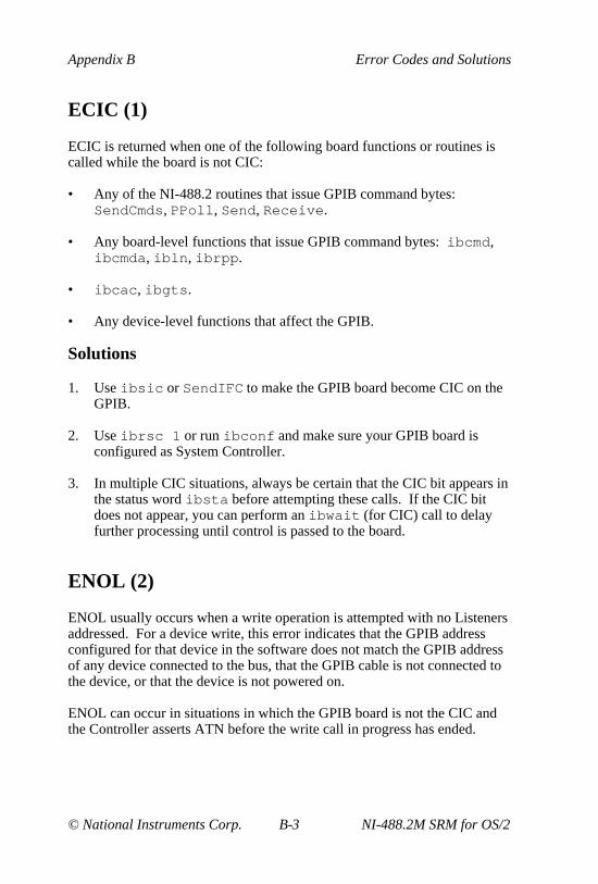
Appendix B Error Codes and Solutions
© National Instruments Corp. B-3 NI-488.2M SRM for OS/2
ECIC (1)
ECIC is returned when one of the following board functions or routines iscalled while the board is not CIC:
• Any of the NI-488.2 routines that issue GPIB command bytes:SendCmds, PPoll , Send, Receive .
• Any board-level functions that issue GPIB command bytes: ibcmd ,ibcmda , ibln , ibrpp .
• ibcac , ibgts .
• Any device-level functions that affect the GPIB.
Solutions
1. Use ibsic or SendIFC to make the GPIB board become CIC on theGPIB.
2. Use ibrsc 1 or run ibconf and make sure your GPIB board isconfigured as System Controller.
3. In multiple CIC situations, always be certain that the CIC bit appears inthe status word ibsta before attempting these calls. If the CIC bitdoes not appear, you can perform an ibwait (for CIC) call to delayfurther processing until control is passed to the board.
ENOL (2)
ENOL usually occurs when a write operation is attempted with no Listenersaddressed. For a device write, this error indicates that the GPIB addressconfigured for that device in the software does not match the GPIB addressof any device connected to the bus, that the GPIB cable is not connected tothe device, or that the device is not powered on.
ENOL can occur in situations in which the GPIB board is not the CIC andthe Controller asserts ATN before the write call in progress has ended.

Error Codes and Solutions Appendix B
NI-488.2M SRM for OS/2 B-4 © National Instruments Corp.
Solutions
1. Make sure that the GPIB address of your device matches the GPIBaddress of the device you want to write data to.
2. If you are using board-level functions, make sure that your device isproperly addressed to listen before writing to it by using ibcmd orsendsetup .
3. Use the appropriate hex code in ibcmd to address your device.
4. Check your cable connections and make sure at least two-thirds of yourdevices are powered on.
5. Call ibpad (or ibsad , if necessary) to match the configured addressto the device switch settings.
6. Reduce the write byte count to that which is expected by the Controller.
EADR (3)
EADR occurs when the GPIB board is CIC and is not properly addressingitself before read and write functions. This error is usually associated withboard-level functions.
EADR is also returned by the function ibgts when the shadow-handshakefeature is requested and the GPIB ATN line is already unasserted. In thiscase, the shadow handshake is not possible and the error is returned to notifyyou of that fact.
Solutions
1. Make sure that the GPIB board is addressed correctly before callingibrd or ibwrt .
2 Avoid calling ibgts except immediately after an ibcmd call (ibcmdcauses ATN to be asserted).

Appendix B Error Codes and Solutions
© National Instruments Corp. B-5 NI-488.2M SRM for OS/2
EARG (4)
EARG results when an invalid argument is passed to a function call. Thefollowing are some examples:
• ibtmo called with a value not in the range 0 through 17.
• ibeos called with meaningless bits set in the high byte of the secondparameter.
• ibpad or ibsad called with invalid addresses.
• ibppc called with invalid parallel poll configurations.
• A board-level function made with a valid device descriptor, or adevice-level function made with a board descriptor.
• An NI-488.2 routine called with an invalid address.
• PPollConfig called with an invalid data line or sense bit.
• Termination parameter in RcvRespMsg and Receive is neitherSTOPend or an 8-bit EOS character.
• eotmode parameter in Send, SendDataBytes , and SendList isnot DABend, NULLend, or NLend.
• In Send, SendDataBytes , or SendList routine, eotmode isDABend and datacnt is 0.
Solutions
1. Make sure that the parameters passed to the NI-488 function or NI-488.2routine are valid.
2. Do not use a device descriptor in a board function or vice versa.
ESAC (5)
ESAC results when ibsic , ibsre , SendIFC , or EnableRemote iscalled when the GPIB board does not have System Controller capability.
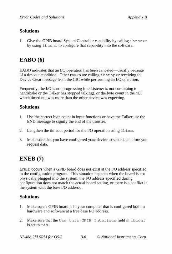
Error Codes and Solutions Appendix B
NI-488.2M SRM for OS/2 B-6 © National Instruments Corp.
Solutions
1. Give the GPIB board System Controller capability by calling ibrsc orby using ibconf to configure that capability into the software.
EABO (6)
EABO indicates that an I/O operation has been canceled—usually becauseof a timeout condition. Other causes are calling ibstop or receiving theDevice Clear message from the CIC while performing an I/O operation.
Frequently, the I/O is not progressing (the Listener is not continuing tohandshake or the Talker has stopped talking), or the byte count in the callwhich timed out was more than the other device was expecting.
Solutions
1. Use the correct byte count in input functions or have the Talker use theEND message to signify the end of the transfer.
2. Lengthen the timeout period for the I/O operation using ibtmo .
3. Make sure that you have configured your device to send data before yourequest data.
ENEB (7)
ENEB occurs when a GPIB board does not exist at the I/O address specifiedin the configuration program. This situation happens when the board is notphysically plugged into the system, the I/O address specified duringconfiguration does not match the actual board setting, or there is a conflict inthe system with the base I/O address.
Solutions
1. Make sure a GPIB board is in your computer that is configured both inhardware and software at a free base I/O address.
2. Make sure that the Use this GPIB Interface field in ibconfis set to Yes.

Appendix B Error Codes and Solutions
© National Instruments Corp. B-7 NI-488.2M SRM for OS/2
EOIP (10)
EOIP occurs when an asynchronous I/O operation has not finished beforesome other call is made. During asynchronous I/O, you can use onlyibstop , ibwait , and ibonl . If any other call is attempted, EOIP isreturned.
With the asynchronous I/O calls (ibcmda , ibrda , ibwrta ), yourapplication can perform additional non-GPIB operations while the I/O is inprogress. Once the asynchronous I/O has begun, further GPIB calls otherthan ibstop , ibwait , or ibonl are strictly limited. If a call interfereswith the I/O operation in progress, it causes the driver to return EOIP.
Solutions
1. Resynchronize the driver and the application before making anyfurther GPIB calls. Resynchronization is accomplished by using oneof the following three functions:
• ibwait If the returned ibsta contains CMPL, the driver and application are resynchronized.
• ibstop The I/O is canceled; the driver and application are resynchronized.
• ibonl The I/O is canceled and the interface is reset; the driverand application are resynchronized.
ECAP (11)
ECAP results when your GPIB board lacks the ability to carry out anoperation or when a particular capability has been disabled in the softwareand a call is made that requires the capability.
Solutions
1. Check the validity of the call, or make sure your GPIB interface boardand the driver both have the needed capability.

Error Codes and Solutions Appendix B
NI-488.2M SRM for OS/2 B-8 © National Instruments Corp.
EFSO (12)
EFSO results when an ibrdf or ibwrtf call encounters a problemperforming a file operation. Specifically, this error indicates that thefunction is unable to open, create, seek, write, or close the file beingaccessed.
Solutions
1. Make sure the filename, path, and drive that you specified are correct.
2. Make sure that the access mode of the file is correct.
3. Make sure there is enough room on the disk to hold the file.
EBUS (14)
EBUS results when certain GPIB bus errors occur during device functions.All device functions send command bytes to perform addressing and otherbus management. Devices are expected to accept these command byteswithin the time limit specified by the configuration program or by ibtmo .EBUS results if a timeout occurred during the sending of these commandbytes.
Solutions
1. Verify that the instrument is operating correctly.
2. Check for loose or faulty cabling or several powered off instrumentson the GPIB.
3. If the timeout period is too short for the driver to send command bytes,increase the timeout period.

Appendix B Error Codes and Solutions
© National Instruments Corp. B-9 NI-488.2M SRM for OS/2
ESTB (15)
ESTB occurs only during the ibrsp function. ESTB indicates that autopolling was not done for a device whose serial poll response queue was full.Several older status bytes are available; however, the oldest is beingreturned by the ibrsp call.
Solutions
1. Call ibrsp more frequently to empty the queue.
2. Disable autopolling with the ibconfig function or the ibconfutility.
ESRQ (16)
ESRQ occurs only during the WaitSRQ routine or ibwait function.ESRQ indicates that the GPIB SRQ line is stuck on. This situation can becaused by the following events:
• Usually, a device unknown to the software is asserting SRQ. Becausethe software does not know of this device, it can never serial poll thedevice and unassert SRQ.
• A GPIB bus tester or similar equipment might be forcing the SRQ lineto be asserted.
• A cable problem, involving the SRQ line, might exist.
• The serial poll response queue of a device that is asserting the SRQ lineis full.
Although the occurrence of ESRQ warns you of a definite GPIB problem, itdoes not affect GPIB operations, except that you cannot depend on the RQSbit while the condition lasts.
Solutions
1. Check to see whether other devices not used by your application areasserting SRQ. Disconnect them from the GPIB if necessary.
2. Call ibrsp for the device whose serial poll queue is full.

Error Codes and Solutions Appendix B
NI-488.2M SRM for OS/2 B-10 © National Instruments Corp.
ETAB (20)
ETAB occurs only during the FindLstn and FindRQS routines. ETABindicates that there was some problem with a table used by these functions.
• In the case of FindLstn , ETAB means that the given table did nothave enough room to hold all the addresses of the Listeners found.
• In the case of FindRQS, ETAB means that none of the devices in thegiven table were requesting service.
Solutions
1. Increase the size of result arrays for FindLstn and FindRQS.

© National Instruments Corp. C-1 NI-488.2M SRM for OS/2
Appendix CCustomer Communication
For your convenience, this appendix contains forms to help you gather theinformation necessary to help us solve technical problems you might haveas well as a form you can use to comment on the product documentation.Filling out a copy of the Technical Support Form before contactingNational Instruments helps us help you better and faster.
National Instruments provides comprehensive technical assistance aroundthe world. In the U.S. and Canada, applications engineers are availableMonday through Friday from 8:00 a.m. to 6:00 p.m. (central time). In othercountries, contact the nearest branch office. You may fax questions to us atany time.
Corporate Headquarters(512) 795-8248Technical support fax: (800) 328-2203
(512) 794-5678
Branch Offices Phone Number Fax NumberAustralia (03) 879 9422 (03) 879 9179Austria (0662) 435986 (0662) 437010-19Belgium 02/757.00.20 02/757.03.11Denmark 45 76 26 00 45 76 71 11Finland (90) 527 2321 (90) 502 2930France (1) 48 14 24 00 (1) 48 14 24 14Germany 089/741 31 30 089/714 60 35Italy 02/48301892 02/48301915Japan (03) 3788-1921 (03) 3788-1923Mexico 95 800 010 0793 95 800 010 0793Netherlands 03480-33466 03480-30673Norway 32-848400 32-848600Singapore 22658862265887Spain (91) 640 0085 (91) 640 0533Sweden 08-730 49 70 08-730 43 70Switzerland 056/20 51 51 056/20 51 55Taiwan 02 377 1200 02 737 4644U.K. 0635 523545 0635 523154

Technical Support Form
Technical support is available at any time by fax. Include the informationfrom the configuration form in your Getting Started Manual. Use additionalpages if necessary.
Name
Company
Address
Fax ( ) Phone ( )
Computer brand
Model Processor
Operating system
Speed MHz RAM MB
Display adapter
Mouse yes no
Other adapters installed
Hard disk capacity MB Brand
Instruments used
National Instruments hardware product model
Revision
Configuration
(continues)

National Instruments software product
Version
Configuration
The problem is
List any error messages
The following steps will reproduce the problem

Documentation Comment Form
National Instruments encourages you to comment on the documentationsupplied with our products. This information helps us provide qualityproducts to meet your needs.
Title: NI-488.2M™ Software Reference Manual for OS/2
Edition Date: January 1995
Part Number: 370950A-01
Please comment on the completeness, clarity, and organization of themanual.
(continues)

If you find errors in the manual, please record the page numbers anddescribe the errors.
Thank you for your help.
Name
Title
Company
Address
Phone ( )
Mail to: Technical PublicationsNational Instruments Corporation6504 Bridge Point Parkway, MS 53-02Austin, TX 78730-5039
Fax to: Technical PublicationsNational Instruments CorporationMS 53-02(512) 794-5678

© National Instruments Corp. G-1 NI-488.2M SRM for OS/2
Glossary
Prefix Meaning Value
n-µ-m-k-M-
nano-micro-milli-kilo-mega-
10-9
10-6
10-3
103
106
A
Acceptor Handshake A GPIB interface function that receives data orcommands. Listeners use this function to receivedata, and all devices use it to receive commands.See Source Handshake and Handshake.
Access Board The GPIB board that controls and communicateswith the devices on the bus that are attached to it.
ANSI American National Standards Institute
API Application Program Interface
ASCII American Standard Code for InformationInterchange
Asynchronous An action or event that occurs at anunpredictable time with respect to the executionof a program.
ATN (Attention) A GPIB line that distinguishes betweencommands and data messages. When ATN isasserted, bytes on the GPIB DIO lines arecommands.

Glossary
NI-488.2M SRM for OS/2 G-2 © National Instruments Corp.
Automatic Serial Polling A feature of the NI-488.2M software in which(Autopolling) serial polls are executed automatically by the
driver whenever a device asserts the GPIB SRQline.
B
Board Function A function that operates on or otherwise pertainsto one of the GPIB interface boards in thecomputer.
C
CIC See Controller-In-Charge.
config.sys An OS/2 file that contains the names of theloadable device driver or driver programs thatOS/2 loads when it is started up.
Controller-In-Charge The device that manages the GPIB by sending(CIC) interface messages to other devices.
D
DAV (Data Valid) One of the three GPIB handshake lines. SeeHandshake.
DCL Device Clear is the GPIB command used to resetthe device or internal functions of all devices.See SDC.
Declaration File A file containing definitions that must be placedat the beginning of an application program.decl.h is the declaration file for C programsusing the NI-488 functions and NI-488.2routines. See Language Interface.
Device Clear See DCL.

Glossary
© National Instruments Corp. G-3 NI-488.2M SRM for OS/2
Device Function A function that operates on or otherwise pertainsto a GPIB device rather than to the GPIBinterface board in the computer. See BoardFunction.
DIO1 through DIO8 The GPIB lines that are used to transmitcommand or data bytes from one device toanother.
DLL dynamic link library
DMA High-speed data transfer between the GPIB(direct memory access) board and memory that is not handled directly by
the CPU. Not available on some systems. SeeProgrammed I/O.
Driver Device driver software installed within theoperating system. Same as an OS/2-installeddevice driver.
DVM digital voltmeter
E
END or END Message A message that signals the end of a data string.END is sent by asserting the GPIB End orIdentify (EOI) line with the last data byte.
EOI A GPIB line that is used to signal either the lastbyte of a data message (END) or the parallel pollIdentify (IDY) message.
EOS or EOS Byte A 7- or 8-bit end-of-string character that is sentas the last byte of a data message.
EOT end of transmission

Glossary
NI-488.2M SRM for OS/2 G-4 © National Instruments Corp.
G
GET Group Execute Trigger is the GPIB commandused to trigger a device or internal function of anaddressed Listener.
Go To Local See GTL.
GPIB General Purpose Interface Bus is the commonname for the communications interface systemdefined in ANSI/IEEE Standard 488.1-1987 andANSI/IEEE Standard 488.2-1987.
GPIB Address The address of a device on the GPIB, composedof a primary address (MLA and MTA) andperhaps a secondary address (MSA). The GPIBboard has both a GPIB address and an I/Oaddress.
GPIB Board Refers to the National Instruments family ofGPIB interface boards.
gpib.sys The NI-488.2M driver file name.
Group Executed Trigger See GET.
GTL Go To Local is the GPIB command used to placean addressed Listener in local (front panel)control mode.
H
Handshake The mechanism used to transfer bytes from theSource Handshake function of one device to theAcceptor Handshake function of another device.The three GPIB lines, DAV, NRFD, and NDAC,are used in an interlocked fashion to signal thephases of the transfer, so that bytes can be sentasynchronously—for example, without a clock—at the speed of the slowest device.
hex hexadecimal

Glossary
© National Instruments Corp. G-5 NI-488.2M SRM for OS/2
High-Level Function A device function that combines severalrudimentary board operations into one functionso that the user does not have to be concernedwith bus management or other GPIB protocolmatters. See Low-Level Function.
Hz hertz
I
ibcnt After each NI-488.2M I/O function, this globalvariable contains the actual number of bytestransmitted.
ibconf The NI-488.2M driver configuration program.
iberr A global variable that contains the specific errorcode associated with a function call that failed.
ibic The Interface Bus Interactive Control program isused to communicate with GPIB devices,troubleshoot problems, and develop yourapplication.
ibsta At the end of each function call, this globalvariable (status word) contains statusinformation.
IFC or Interface Clear A GPIB line used by the System Controller toinitialize the bus. See DCL and SDC.
Interface Message A broadcast message sent from the Controller toall devices and used to manage the GPIB.
I/O (Input/Output) In the context of this manual, the transmission ofcommands or messages between the computervia the GPIB board and other devices on theGPIB.
Glossary
NI-488.2M SRM for OS/2 G-6 © National Instruments Corp.
I/O Address The address of the GPIB board from the point ofview of the CPU, as opposed to the GPIBaddress of the GPIB board. Also called portaddress or board address.
ist An Individual Status bit of the status byte used inthe Parallel Poll Configure function.
L
LAD or Listen Address See MLA.
Language Interface Code that enables an application program thatuses NI-488.2M functions or NI-488.2M routinesto access the driver.
Listen Address See MLA.
Listener A GPIB device that receives data messages froma Talker.
LLO Local Lockout is the GPIB command used to tellall devices that they may or should ignore remote(GPIB) data messages or local (front panel)controls, depending on whether the device is inlocal or remote program mode.
Low-Level Function A rudimentary board or device function thatperforms a single operation. See High-LevelFunction.
M
Make File Utility that compiles and links programs.
MB Megabytes of memory.
Memory-Resident Resident in RAM.
MLA A GPIB command used to address a device to be(My Listen Address) a Listener. There are 31 primary addresses.

Glossary
© National Instruments Corp. G-7 NI-488.2M SRM for OS/2
MSA My Secondary Address is the GPIB commandused to address a device to be a Listener or aTalker when extended (two byte) addressing isused. The complete address is an MLA or MTAaddress followed by an MSA address. There are31 secondary addresses for a total of 961 distinctlisten or talk addresses for devices.
MTA (My Talk Address) A GPIB command used to address a device to bea Talker. There are 31 primary addresses.
Multitasking The concurrent processing of more than oneprogram or task. OS/2 provides a multitaskingenvironment so that multiple applications canexecute at the same time.
N
NDAC One of the three GPIB handshake lines. See(Not Data Accepted) Handshake.
NRFD One of the three GPIB handshake lines. See(Not Ready For Data) Handshake.
O
Open Device or Board One that has been enabled or placed online by asystem or language open function.
P
Parallel Poll The process of polling all configured devices atonce and reading a composite poll response. SeeSerial Poll.
PIO See Programmed I/O.

Glossary
NI-488.2M SRM for OS/2 G-8 © National Instruments Corp.
PPC Parallel Poll Configure is the GPIB command(Parallel Poll Configure) used to configure an addressed Listener to
participate in polls.
PPD Parallel Poll Disable is the GPIB command used(Parallel Poll Disable) to disable a configured device from participating
in polls. There are 16 PPD commands.
PPE Parallel Poll Enable is the GPIB command used(Parallel Poll Enable) to enable a configured device to participate in
polls and to assign a DIO response line. Thereare 16 PPE commands.
PPU Parallel Poll Unconfigure is the GPIB command(Parallel Poll used to disable any device from participating inUnconfigure) polls.
Programmed I/O Low-speed data transfer between the GPIB boardand memory in which the CPU moves each databyte according to program instructions. SeeDMA.
R
RAM random-access memory
REN (Remote Enable) A GPIB line controlled by the System Controllerbut used by the CIC to place devices in remoteprogram mode.
RQS Request Service
S
s seconds
SDC Selected Device Clear is the GPIB commandused to reset internal or device functions of anaddressed Listener. See DCL and IFC.
Glossary
© National Instruments Corp. G-9 NI-488.2M SRM for OS/2
Serial Poll The process of polling and reading the statusbyte of one device at a time. See Parallel Poll.
Service Request See SRQ.
Source Handshake The GPIB interface function that transmits dataand commands. Talkers use this function to senddata, and the Controller uses it to sendcommands. See Acceptor Handshake andHandshake.
SPD Serial Poll Disable is the GPIB command used to(Serial Poll Disable) cancel an SPE command.
SPE Serial Poll Enable is the GPIB command used to(Serial Poll Enable) enable a specific device to be polled. That
device must also be addressed to talk. See SPD.
SRQ (Service Request) The GPIB line that a device asserts to notify theCIC that the device needs servicing.
Status Byte The data byte sent by a device when it is seriallypolled.
Status Word See ibsta.
Synchronous Refers to the relationship between theNI-488.2M driver functions and a process whenexecuting driver functions is predictable; theprocess is blocked until the OS/2 drivercompletes the function.
System Controller The single-designated Controller that can assertcontrol (become CIC of the GPIB) by sendingthe Interface Clear (IFC) message. Otherdevices can become CIC only by having controlpassed to them.

Glossary
NI-488.2M SRM for OS/2 G-10 © National Instruments Corp.
T
TAD (Talk Address) See MTA.
Talker A GPIB device that sends data messages toListeners.
TCT Take Control is the GPIB command used to passcontrol of the bus from the current Controller toan addressed Talker.
Timeout A feature of the NI-488.2M driver that preventsI/O functions from hanging indefinitely whenthere is a problem on the GPIB.
TLC An integrated circuit that implements most of theGPIB Talker, Listener, and Controller functionsin hardware.
U
ud (unit descriptor) A variable name and first argument of eachfunction call that contains the unit descriptor ofthe GPIB interface board or other GPIB devicethat is the object of the function.
UNL Unlisten is the GPIB command used tounaddress any active Listeners.
UNT Untalk is the GPIB command used to unaddressan active Talker.

© National Instruments Corp. I-1 NI-488.2M SRM for OS/2
Index
Numbers/Symbols
! (repeat previous function), ibicutility, 5-21
$ (execute indirect file) function,ibic utility, 5-23
+ (turn on display) function, ibicutility, 5-21 to 5-22
- (turn off display) function, ibicutility, 5-21 to 5-22
A
addressesbase I/O address, 7-14ENEB error code, B-6ENOL error code, B-3 to B-4primary GPIB address, 7-10secondary GPIB address, 7-10
addressingenable repeat addressing, 7-15repeat addressing, 4-6
AllSpoll function, 6-6, 6-7, 6-8ANSI/IEEE Standard
488.1-1987, 1-5ANSI/IEEE Standard
488.2-1987, 1-5API interface. See OS/2 API
interface.application examples
asynchronous I/O, 2-6 to 2-7basic communication, 2-2
to 2-3with IEEE 488.2 compliant
devices, 2-14 to 2-15clearing and triggering devices,
2-4 to 2-5end-of-string mode, 2-8 to 2-9files on distribution disk, 1-1 to
1-2, 2-1
non-controller, 2-21 to 2-22parallel polls, 2-18 to 2-20serial polls using NI-488.2
routines, 2-16 to 2-17service requests, 2-10 to 2-13
applications, debuggingchecking global variable
status, 4-3communication errors, 4-6configuration errors, 4-4GPIB error codes, 4-3 to 4-4ibic, 4-3ibtest, 4-1 to 4-2reconfiguring NI-488.2M
software, 4-5repeat addressing, 4-6termination method, 4-6timing errors, 4-5
applications, writing. See alsoapplication examples.
choosing programming method,3-1 to 3-4
compiling and linking programs16-bit C applications, 3-2132-bit C applications, 3-20
to 3-21ibic for communicating with
devices, 3-7NI-488 applications, 3-7 to 3-12
clearing devices, 3-10configuring devices, 3-10items to include, 3-7NI-488 program shell, 3-8opening devices, 3-9placing devices
offline, 3-12processing data, 3-12reading measurement, 3-12triggering devices, 3-10
to 3-11

Index
NI-488.2M SRM for OS/2 I-2 © National Instruments Corp.
waiting formeasurement, 3-11
NI-488.2 applications, 3-13to 3-20
configuringinstruments, 3-17
finding all listeners, 3-15identifying
instruments, 3-16initialization, 3-15initializing
instruments, 3-17items to include, 3-13NI-488.2 program
shell, 3-14placing board offline, 3-20processing data, 3-19reading measurement, 3-19triggering
instruments, 3-18waiting for measurement,
3-18 to 3-19NI-488.2 language interface,
3-1 to 3-4advantages, 3-1 to 3-2NI-488 functions, 3-2
to 3-3NI-488.2 routines, 3-3
to 3-4OS/2 API interface, 3-4running applications, 3-21status checking using global
variables, 3-4 to 3-6ibcnt and ibcntl (count
variables), 3-6iberr (error variable), 3-6ibsta (status word), 3-4
to 3-5asynchronous I/O
EOIP error code, B-7example, 2-6 to 2-7
AT-GPIB boards, ibtest checking of,4-1 to 4-2
ATN (attention) line (table), 1-7
ATN status, A-4automatic serial polling
enabling, 7-13interrupts and, 6-5procedure for, 6-4 to 6-5stuck SRQ state and, 6-5
auxiliary functions, ibic. See ibicutility.
B
base I/O address, 7-14board configuration. See ibconf
utility.board functions. See NI-488
functions.boards
disabling access to, 7-14ibtest checking of
AT-GPIB boards, 4-1to 4-2
GPIB boards, 4-2bus management, 6-2 to 6-3bus timing, configuring, 7-13
C
cables, ibtest checking of, 4-2CIC. See Controller-in-Charge.CIC status, A-4clearing and triggering devices
(example), 2-4 to 2-5CMPL status, A-3communication errors
repeat addressing, 4-6termination method, 4-6
communication examplesbasic communication with IEEE
488.2 compliant devices, 2-14to 2-15

Index
© National Instruments Corp. I-3 NI-488.2M SRM for OS/2
communication between hostand GPIB device, 2-2 to 2-3
compiling applications16-bit C applications, 3-2132-bit C applications, 3-20
to 3-21configuration errors, 4-4configuration of GPIB systems, 1-7
to 1-9. See also ibconf utility.Controller-in-Charge
activating CIC protocol,6-3, 7-13
CIC status, A-4configuring GPIB board as, 6-2
to 6-3definition, 1-6EADR error code, B-4ECIC error code, B-3
Controllers. See also SystemController.
definition, 1-5non-controller (example), 2-21
to 2-22controlling more than one board, 1-9count return, by ibic, 5-10count variables. See ibcnt and ibcntl
(count variables).customer communication, xv, C-1
D
data lines, GPIB, 1-6data transfer termination methods, 6-
1 to 6-2DAV (data valid) handshake line
(table), 1-6DCAS status, A-5debugging applications. See
applications, debugging.default configurations in
ibconf, 7-16
description level of ibconf utility.See ibconf utility.
DevClear routine, 3-17developing applications. See
applications, writing.device configuration. See ibconf
utility.device functions. See NI-488
functions.device-level calls, 6-2 to 6-3devices
clearing, 3-10configuring, 3-10DCAS status, A-5DTAS status, A-5opening, 3-9, 5-13 to 5-16placing offline, 3-12triggering, 3-10 to 3-11
DMA channel, configuring, 7-14documentation
conventions used in manual, xii-xiii
organization of manual, xi-xiirelated documentation, xvusing the manual set, xiv
driver utilities, 1-1DTAS status, A-5
E
EABO error code, B-6EADR error code, B-4EARG error code, 5-15, B-5EBUS error code, B-8ECAP error code, B-7ECIC error code, 6-3, B-3EDVR error code, 5-15, B-2EFSO error code, B-8end of string (EOS)
adding characters in ibic, 5-9end-of-string mode (example),
2-8 to 2-9

Index
NI-488.2M SRM for OS/2 I-4 © National Instruments Corp.
END status, A-2EOS byte, 7-11EOS mode configuration, 6-1
to 6-2terminate read on EOS, 7-11type of compare on EOS, 7-11
end of transmission (EOT)mode, 6-1
end or identify (EOI) line. See EOI(end or identify) line.
END status, A-2ENEB error code, 5-15, B-6ENOL error code, B-3 to B-4EOI (end or identify) line
description (table), 1-7END status, A-2send EOI at end of write, 7-12set EOI with EOS on
writes, 7-11terminating data transfers, 6-1
EOIP error code, B-7EOS. See end of string (EOS).EOS byte, 7-11EOT mode, 6-1ERR status, A-2error codes. See also ibsta (status
word).EABO, B-6EADR, 5-15, B-4EARG, B-5EBUS, B-8ECAP, B-7ECIC, 6-3, B-3EDVR, 5-15, B-2EFSO, B-8ENEB, 5-15, B-6ENOL, B-3 to B-4EOIP, B-7ESAC, B-5 to B-6ESRQ, B-9ESTB, B-9ETAB, B-10GPIB, 4-3 to 4-4returned by ibic, 5-10
summary (table), B-1error variable (iberr). See iberr
(error variable).errors
communication errors, 4-6repeat addressing, 4-6termination method, 4-6
configuration errors, 4-4GPIB-specific errors,
selecting, 7-12timing errors, 4-5
ESAC error code, B-5 to B-6ESB (Event Status) bit, 6-4ESRQ error code, 6-5, B-9ESTB error code, B-9ETAB error code, B-10Event Status bit (ESB), 6-4examples. See application
examples.execute indirect file ($) function,
ibic utility, 5-23
F
files for NI-488.2M software. SeeNI-488.2M software.
FindLstn routine, 3-15FindRQS function, 6-7, 6-8functions. See NI-488 functions.
G
General Purpose Interface Bus(GPIB). See GPIB operation;GPIB programming.
global variableschecking status, 3-4 to 3-6debugging applications, 4-3ibcnt and ibcntl (count
variables), 3-6, 4-3iberr (error variable), 3-6, 4-3

Index
© National Instruments Corp. I-5 NI-488.2M SRM for OS/2
ibsta (status word), 3-4 to 3-5,4-3, A-1 to A-5
GPIB boards, ibtest checking of, 4-2GPIB cables, ibtest checking of, 4-2GPIB operation, 1-5 to 1-9
controlling more than oneboard, 1-9
data lines, 1-6handshake lines, 1-6IEEE 488 standard, 1-5interface management lines, 1-7sending messages, 1-6 to 1-7setting up and configuring, 1-7
to 1-9talkers, listeners, and
controllers, 1-5GPIB programming
bus management, 6-2 to 6-3device-level calls, 6-2 to 6-3parallel polling
implementation of, 6-9to 6-12
with NI-488 functions,6-10 to 6-12
with NI-488.2 routines, 6-9to 6-10
serial pollingautomatic, 6-4 to 6-5service requests
from IEEE 488devices, 6-3
from IEEE 488.2devices, 6-4
SRQ and serial pollingwith NI-488 device
functions, 6-6with NI-488.2 routines,
6-6 to 6-8termination of data transfers,
6-1 to 6-2waiting for GPIB
conditions, 6-2
H
handshake linesDAV (table), 1-6NDAC (table), 1-6NRFD (table), 1-6overview, 1-6
Help function, ibic utility** caps ?? **, 5-20
I
ibclr function, 3-10ibcnt and ibcntl (count variables)
debugging applications, 4-3description, 3-6
ibconf utilityactivating CIC protocol, 6-3board and device configuration
optionsassert REN when SC, 7-12base I/O address, 7-14bus timing, 7-13DMA channel, 7-14enable auto serial
polling, 7-13enable CIC protocol, 7-13enable repeat
addressing, 7-15EOS byte, 7-11GPIB-specific errors, 7-12interrupt jumper
setting, 7-15parallel poll duration, 7-13primary GPIB
address, 7-10secondary GPIB
address, 7-10send EOI at end of
write, 7-12serial poll timeout, 7-15

Index
NI-488.2M SRM for OS/2 I-6 © National Instruments Corp.
set EOI with EOS onwrites, 7-11
System Controller, 7-12terminate read on
EOS, 7-11timeout setting, 7-10type of compare on
EOS, 7-11use this GPIB
interface, 7-14default configurations, 7-16description level
change characteristicsoption, 7-8
help option, 7-8illustration, 7-7next board/device
option, 7-8overview, 7-7reset value option, 7-8return to map option, 7-8
exiting, 7-17input selection level, 7-2 to 7-3map level
device map of boardsoption, 7-5
(dis)connect option, 7-6edit option, 7-6exit option, 7-6help option, 7-5illustration, 7-4purpose, 7-4rename option, 7-5
output selection level, 7-9overview, 7-1starting, 7-1
ibconfig functionactivating CIC protocol, 6-3autopolling, 6-4determining EOI line
assertion, 6-2dynamic configuration of
drivers, 7-1
reconfiguring NI-488.2Msoftware, 4-5
ibdev functionEARG error, 5-15EDVR error, 5-15ENEB error, 5-15ibic utility, 5-13 to 5-16opening devices, 3-9parallel polling, 6-11
ibeos function, 6-1ibeot function, 6-1iberr (error variable)
debugging applications, 4-3description, 3-6
ibfind functionibic utility, 5-13opening devices, 3-9
ibic utilityauxiliary functions, 5-18
to 5-24! (repeat previous
function), 5-21$ (execute indirect
file), 5-23+ (turn on display), 5-21
to 5-22- (turn off display), 5-21
to 5-22Help, 5-20n* (repeat function n
times), 5-22 to 5-23print (display ASCII
string), 5-24Set, 5-11, 5-19 to 5-20summary (table), 5-18
to 5-19communicating with
devices, 3-7count return, 5-10debugging applications, 4-3end-of-string characters, 5-9error codes return, 5-10examples

Index
© National Instruments Corp. I-7 NI-488.2M SRM for OS/2
NI-488 board functions,5-31 to 5-35
NI-488 device functions,5-28 to 5-30
NI-488.2 routines, 5-24to 5-27
exiting, 5-2NI-488 functions
common functions, 5-13to 5-17
ibdev, 5-13 to 5-16ibfind, 5-13ibrd, 5-17ibwrt, 5-16syntax, 5-3 to 5-4
NI-488.2 routinescommon routines, 5-11
to 5-12Receive, 5-12Send, 5-11 to 5-12syntax, 5-5 to 5-6
overview, 5-1starting, 5-1 to 5-2status word return, 5-9syntax, 5-2 to 5-8
NI-488 functions, 5-3to 5-4
NI-488.2 routines, 5-5to 5-6
notes, 5-7 to 5-8ibist function, 6-11ibonl function, 3-12, 3-20ibppc function, 6-10 to 6-12ibrd function
ibic utility, 5-17reading measurements, 3-12
ibrpp function, 6-12ibrsp function
autopolling, 6-4 to 6-5serial polling, 6-6
ibsta (status word)ATN status, A-4CIC status, A-4CMPL status, A-3
DCAS status, A-5debugging applications, 4-3description, 3-4 to 3-5DTAS status, A-5END status, A-2ERR status, A-2LACS status, A-5layout (table), 3-5LOK status, A-3REM status, A-4returned by ibic, 5-9RQS status, A-3SRQI status, A-2summary (table), A-1TACS status, A-4TIMO status, A-2
ibtest, 4-1 to 4-2GPIB cables connected, 4-2incorrect interrupt level, 4-2presence test
of driver, 4-1 to 4-2of GPIB board, 4-1 to 4-2
ibtrg function, 3-10ibwait function
clearing stuck SRQcondition, 6-5
purpose and use, 6-2serial polling, 6-6waiting for measurements, 3-11
ibwrt functionconfiguring devices, 3-10ibic utility, 5-16
IEEE 488 standards, 1-5IFC (interface clear) interface
management line (table), 1-7input selection level of ibconf
utility. See ibconf utility.instruments
configuring, 3-17identifying, 3-16initializing, 3-17triggering, 3-18
Interface Bus Interactive Controlutility. See ibic utility.

Index
NI-488.2M SRM for OS/2 I-8 © National Instruments Corp.
interface management lines (table)ATN, 1-7EOI, 1-7IFC, 1-7REN, 1-7SRQ, 1-7
interruptsautopolling and, 6-5checking for incorrect level
with ibtest, 4-2jumper settings, 7-15
L
LACS status, A-5language-related files, 1-2linking applications
16-bit C applications, 3-2132-bit C applications, 3-20
to 3-21Listeners
definition, 1-5finding all listeners, 3-15LACS status, A-5
LOK status, A-3
M
manual. See documentation.map level of ibconf utility. See
ibconf utility.MAV (Message Available) bit, 6-4measurements
readingibrd function, 3-12Receive function, 3-19
waiting foribwait function, 3-11WaitSRQ routine, 3-18
Message Available bit (MAV), 6-4messages, sending across GPIB, 1-6
to 1-7
N
n* (repeat function n times)function, ibic utility, 5-22 to 5-23
NDAC (not data accepted)handshake line (table), 1-6
NI-488 applications, writing. Seeapplications, writing.
NI-488 functions, 3-2 to 3-3. Seealso specific functions.
advantages, 3-2board functions
description, 3-3ibic utility examples, 5-31
to 5-35device functions
description, 3-2ibic utility examples, 5-28
to 5-30ibic utility
common functions, 5-13to 5-17
ibdev, 5-13 to 5-16ibfind, 5-13ibrd, 5-17ibwrt, 5-16syntax, 5-3 to 5-4
parallel polling, 6-10 to 6-12when to use, 3-2
NI-488.2 applications, writing. Seeapplications, writing.
NI-488.2 language interface, 3-1to 3-4
advantages, 3-1 to 3-2NI-488 functions, 3-2 to 3-3NI-488.2 routines, 3-3 to 3-4
NI-488.2 routines. See also specificroutines.

Index
© National Instruments Corp. I-9 NI-488.2M SRM for OS/2
ibic utilitycommon routines, 5-11
to 5-12examples, 5-24 to 5-27Receive, 5-12Send, 5-11 to 5-12syntax, 5-5 to 5-6
parallel polling, 6-9 to 6-10when to use, 3-3writing applications, 3-3 to 3-4
NI-488.2M driver, 1-1, 1-4NI-488.2M software
API-related files, 1-3driver utilities, 1-1example program files, 1-2
to 1-3files on distribution disk, 1-1language-related files, 1-2NI-488.2M driver, 1-1OS/2 operation, 1-4 to 1-5reconfiguring, 4-5
non-controller (example), 2-21to 2-22
NRFD (not ready for data)handshake line (table), 1-6
O
OS/2 API interfaceAPI-related files, 1-3using the OS/2 API
interface, 3-4OS/2 operating system, 1-4 to 1-5output selection level of ibconf
utility. See ibconf utility.
P
parallel pollingexample, 2-18 to 2-20implementation of, 6-9 to 6-12
with NI-488 functions, 6-10to 6-12
with NI-488.2 routines, 6-9to 6-10
setting duration of, 7-13paths, including in LIBPATH
statement, 3-21PPoll routine, 6-10PPollUnconfig routine, 6-10primary GPIB address, 7-10print (display ASCII string)
function, ibic utility, 5-24program shells
NI-488, 3-8NI-488.2, 3-14
programming. See applications,writing; GPIB programming.
programming examples. Seeapplication examples.
R
ReadStatusByte routine, 3-18, 6-7Receive function, 3-19Receive routine
ibic utility, 5-12identifying instruments, 3-16
reconfiguring NI-488.2Msoftware, 4-5
REM status, A-4REN (remote enable) line
configuring assertion of, 7-12description (table), 1-7
repeat function n times (n*)function, ibic utility, 5-22 to 5-23
repeat previous function (!), ibicutility, 5-21
routines. See NI-488.2 routines.RQS status, A-3

Index
NI-488.2M SRM for OS/2 I-10 © National Instruments Corp.
S
secondary GPIB address, 7-10Send routine
configuring instruments, 3-17ibic utility, 5-11 to 5-12
SendIFC routine, 3-15serial polling
automatic, 6-4 to 6-5enabling, 7-13interrupts and, 6-5procedure for, 6-4 to 6-5stuck SRQ state and, 6-5
service requestsfrom IEEE 488
devices, 6-4from IEEE 488.2
devices, 6-4SRQ and serial polling
with NI-488 devicefunctions, 6-6
with NI-488.2 routines, 6-6to 6-8
timeout value, setting, 7-15using NI-488.2 routines
(example), 2-16 to 2-17service requests
automatic serial polling, 6-4to 6-5
example, 2-10 to 2-13RQS status, A-3serial polling
IEEE 488 devicefunctions, 6-6
IEEE 488.2 routines, 6-6to 6-8
SRQI status, A-2Set function
description, 5-19 to 5-20selecting NI-488.2 function
mode, 5-11SRQ (service request) line
application example, 2-10to 2-13
description (table), 1-7ESRQ error code, B-9requesting service, 6-3serial polling
with NI-488 devicefunctions, 6-6
with NI-488.2 routines, 6-6to 6-8
stuck SRQ state, 6-5SRQI status, A-2standards
ANSI/IEEE Standard488.1-1987, 1-5
ANSI/IEEE Standard488.2-1987, 1-5
status variables. See globalvariables.
status word variable. See ibsta(status word).
stuck SRQ condition, 6-5System Controller
configuring, 7-12definition, 1-6
T
TACS status, A-4Talkers
definition, 1-5TACS status, A-4
technical support, C-1terminate read on EOS, 7-11termination methods
data transfer termination, 6-1to 6-2
device termination methods, 4-6TestSRQ routine, 3-18, 6-7timeout setting
configuring, 7-10serial polls, 7-15

Index
© National Instruments Corp. I-11 NI-488.2M SRM for OS/2
timing errors, 4-5TIMO status, A-2*TRG command, 3-18Trigger routine, 3-18triggering GPIB devices (example),
2-4 to 2-5turn off display (-) function, ibic
utility, 5-21 to 5-22turn on display (+) function, ibic
utility, 5-21 to 5-22
WWaitSRQ routine, 3-18, 6-7, 6-8writing applications. See
applications, writing.