Embed Size (px)
Citation preview

Software Manual
KuDA View

Software Manual
KuDA View
Copyright © 1997 Kaman Instrumentation Corporation PART NO: 860117-002 1500 Garden of the Gods Road Rev. B1 Colorado Springs, CO 80907

Kaman Instrumentation
1500 Garden of the Gods Road Colorado Springs, CO 80907
(719) 599-1919
PROPRIETARY INFORMATION KuDA View© and KuDASoft© contain information PROPRIETARY to Kaman Instrumentation Corporation, a
Kaman Company. Any reproduction, disclosure or other use of this information is expressly prohibited except as Kaman Instrumentation may otherwise agree to by writing
KuDA Soft© and KuDA View© are Trademarks of Kaman Instrumentation Microsoft is a registered trademark and Microsoft Excel, Microsoft Windows and Microsoft Windows 95 are trademarks of Microsoft Corporation IBM is a registered trademark

KAMAN INSTRUMENTATION CORPORATION PLEASE READ CAREFULLY - DO NOT DISCARD
THIS IS A LEGAL AGREEMENT.
BY USING THIS SOFTWARE OR BREAKING THE SEAL ON THIS DISKETTE PACKAGE YOU ACCEPT THIS LICENSE AGREEMENT AND WARRANTY AND YOU AGREE TO THESE TERMS AND CONDITIONS.
LICENSE. This is a license agreement between you and Kaman Instrumentation Corporation ("Kaman"). Kaman grants you the non-exclusive right to use the enclosed Kaman software program ("SOFTWARE") on the original single computer terminal provided with the SOFTWARE in stand-alone operation, or with the original computer interfacing with Kaman's computer network and any related documentation. You do not have the right to install or use the SOFTWARE on any other computer. COPYRIGHT AND BACKUP. The SOFTWARE is owned by Kaman or its suppliers and is protected by United States copyright laws and international treaty provisions. You may make one copy of the SOFTWARE solely for backup or archival purposes, as long as the copyright and proprietary notices in this license are included in the copy. You may not reverse engineer, decompile, disassemble, or create derivative works from the software. TERMINATION OF LICENSE. You may terminate this license by destroying the SOFTWARE together with any backup copy. This license will also terminate if you fail to comply with any term or condition of this Agreement. You agree upon such termination to destroy the SOFTWARE together with any backup copy of the SOFTWARE. OTHER RESTRICTIONS. As the original purchaser of the Kaman Hardware System and SOFTWARE, you are the registered licensee. You may not sell, lease, or otherwise transfer your rights to the Hardware or license rights to the SOFTWARE without the express written consent of Kaman. If this software package contains both 3 1/2" and 5 1/4" disks, then you may use only the disks configured for your single user computer. You may not use the other disks on any other computer or computer network. All such SOFTWARE is subject to all the provisions of this agreement. LIMITED WARRANTY. Kaman does not warrant that the SOFTWARE will meet your requirements, that operation of the SOFTWARE will be uninterrupted or error-free, or that all SOFTWARE errors will be corrected. Kaman is not responsible for problems caused by changes in the operating characteristics of computer hardware or computer operating systems which are made after the release of the SOFTWARE nor for problems in the interaction of the SOFTWARE with non-Kaman software. Kaman will have no responsibility to replace or refund the license fee of media damaged by accident, abuse, or misapplication. THE ABOVE WARRANTIES ARE EXCLUSIVE AND IN LIEU OF ALL OTHER WARRANTIES, EXPRESS OR IMPLIED, INCLUDING WARRANTIES OF MERCHANTABILITY, FITNESS FOR A PARTICULAR PURPOSE AND NON-INFRINGEMENT. NO ORAL OR WRITTEN INFORMATION OR ADVICE GIVEN BY KAMAN, ITS EMPLOYEES, DISTRIBUTORS, OR AGENTS SHALL INCREASE THE SCOPE OF THE ABOVE WARRANTIES OR CREATE ANY NEW WARRANTIES. SOME STATES DO NOT ALLOW THE EXCLUSION OF IMPLIED WARRANTIES, SO THE ABOVE EXCLUSION MAY NOT APPLY TO YOU. IN THAT EVENT, ANY IMPLIED WARRANTIES ARE LIMITED IN DURATION TO THIRTY (30) DAYS FROM THE DATE OF SHIPMENT OF THE SOFTWARE. LIMITATION OF REMEDIES. IN NO EVENT WILL KAMAN BE LIABLE TO YOU FOR ANY SPECIAL, CONSEQUENTIAL, INDIRECT OR SIMILAR DAMAGES, INCLUDING ANY LOST PROFITS OR LOST DATA ARISING OUT OF THE USE OR INABILITY TO USE THE SOFTWARE OR ANY DATA SUPPLIED THEREWITH EVEN IF KAMAN OR ANYONE ELSE HAS BEEN ADVISED OF THE POSSIBILITY OF SUCH DAMAGES OR FOR ANY CLAIM BY ANY OTHER PARTY. IN NO CASE SHALL KAMAN'S LIABILITY EXCEED THE PURCHASE PRICE FOR THE SOFTWARE. GOVERNMENT LICENSEE. If you are acquiring the SOFTWARE on behalf of any unit or agency of the United States Government, the following provisions apply: The Government acknowledges Kaman's representation that the SOFTWARE and its documentation were developed at private expense and no part thereof is in the public domain. The Government acknowledges Kaman representation that the SOFTWARE is "Restricted Computer Software" as that term is defined in Clause 52.227-19 of the Federal Acquisition Regulations (FAR) and is "Commercial Computer Software" as that term is defined in Subpart 227.471 of the Department of Defense Federal Acquisition Supplement (DFARS). The Government agrees that: (i) if the SOFTWARE is supplied to the Department of Defense (DOD), the SOFTWARE is classified as "Commercial Computer Software" and the Government is acquiring only "restricted rights" in the SOFTWARE and its documentation as that term is defined in Clause 252.227-7013(c)(1) of the DFARS and (ii) if the SOFTWARE is supplied to any unit or agency of the United States Government other than DOD, the Government's rights in the SOFTWARE and its documentation will be as defined in Clause 52.227-19(c)(2) of the FAR. EXPORT LAW ASSURANCES. You acknowledge and agree that the SOFTWARE is subject to restrictions and controls imposed by the United States Export Administration Act (the "Act") and the regulations thereunder. You agree and certify that neither the SOFTWARE nor any direct product thereof is being or will be acquired, shipped, transferred or reexported, directly or indirectly, into any country prohibited by the Act and the regulations thereunder or will be used for any purposes prohibited by the same. GENERAL. This agreement will be governed by the laws of the State of Colorado. Should you have any questions concerning this agreement, or if you desire to contact Kaman for any reason, please write: Kaman Instrumentation Corporation, Customer Service, P. O. Box 7463, Colorado Springs, CO 80933.

KuDA View© Software Manual Contents • v
Contents
Getting Started 1 Introduction................................................................................................................................1 Overview....................................................................................................................................1
System Components ....................................................................................................1 System Requirements ..................................................................................................1 Installing KuDAView..................................................................................................2 Starting KuDAView ....................................................................................................2
KuDA Commands 5 Overview....................................................................................................................................5 File Menu...................................................................................................................................5
Connect to KuDA ........................................................................................................5 Close KuDA ................................................................................................................5 Find KuDA's................................................................................................................5 Save KuDA View Setup .............................................................................................6 Load KuDA View Setup.............................................................................................7 Save KuDA Configuration ..........................................................................................7 Load KuDA Configuration..........................................................................................8 Start All........................................................................................................................8 Stop All........................................................................................................................8 Download ....................................................................................................................8
Edit Menu ................................................................................................................................11 Configuration.............................................................................................................11 Initialize KuDA .........................................................................................................12 Password....................................................................................................................12 AutoSetup ..................................................................................................................13 Thickness Setup.........................................................................................................14 Calibration Tables......................................................................................................15 Other Parameters .......................................................................................................16 Sensor Ranges............................................................................................................18 KuDA Limits .............................................................................................................19
View Menu ..............................................................................................................................22 Toolbar ......................................................................................................................22 Status Bar...................................................................................................................23 Configuration.............................................................................................................23 Terminal.....................................................................................................................23 KuDA Status..............................................................................................................24
Calibrate...................................................................................................................................24 Temp Comp Sensor 1 ................................................................................................24 Temp Comp Sensor 2 ................................................................................................26 Distance Sensor 1 ......................................................................................................26 Distance Sensor 2 ......................................................................................................27
Window....................................................................................................................................27 New Chart..................................................................................................................27

vi • Contents KuDA View© Software Manual
Cascade ......................................................................................................................27 Tile.............................................................................................................................27 Arrange Icons.............................................................................................................27
Help..........................................................................................................................................28 Index ..........................................................................................................................28 About KuDAView.....................................................................................................28
The KuDA Window 29 Overview..................................................................................................................................29 Data Displays ...........................................................................................................................29
Function .....................................................................................................................29 Sensor 1 Output .........................................................................................................30 Sensor 2 Output .........................................................................................................30
Control Buttons ........................................................................................................................31 Zero............................................................................................................................31 Run/Stop ....................................................................................................................31 StripChart...................................................................................................................31 Close ..........................................................................................................................31 Configure ...................................................................................................................31 Calibrate.....................................................................................................................31
Display Labels..........................................................................................................................32 Scroll Bars................................................................................................................................32
Chart Commands 33 Overview..................................................................................................................................33 Chart.........................................................................................................................................33
Configure ...................................................................................................................33 Rescale .....................................................................................................................................36 Erase.........................................................................................................................................36 Close ........................................................................................................................................36 Window....................................................................................................................................36
Cascade ......................................................................................................................36 Tile.............................................................................................................................36 Arrange Icons.............................................................................................................36
Help..........................................................................................................................................36
The Chart Window 37 Overview..................................................................................................................................37
Chart ..........................................................................................................................37 Legend .......................................................................................................................37 Log Button .................................................................................................................38 Log Display ...............................................................................................................38 Axis Limits ................................................................................................................38 Re-scale Button..........................................................................................................38 Right Mouse Button...................................................................................................38
Communication Viewer 39 Overview..................................................................................................................................39
Menu..........................................................................................................................39
Log File Format 41 Description ...............................................................................................................................41

KuDA View© Software Manual Contents • vii
Example 1 ..................................................................................................................41 Example 2 ..................................................................................................................41 Example 3 ..................................................................................................................42
Editing KuDAView.INI 43 Description...............................................................................................................................43
LastSetupFile .............................................................................................................44 Parameters .................................................................................................................44 InitStrings ..................................................................................................................44 Settings ......................................................................................................................44 Setup Files .................................................................................................................45
Communicating with KuDA Soft 47 Caution:....................................................................................................................................47 Conventions: ............................................................................................................................47 The KuDA Address: ................................................................................................................47 The KuDA Soft Prompt: ..........................................................................................................47 Communication Modes: ...........................................................................................................48 Command Strings: ...................................................................................................................48 The Checksum: ........................................................................................................................48 Commonly Used Commands: ..................................................................................................49
Mode 0 Commands:...................................................................................................49 Mode 1 Commands:...................................................................................................50 Mode 2 Commands:...................................................................................................50 Mode 4 Commands:...................................................................................................51 Mode 5 Commands:...................................................................................................53 Mode 6 Commands:...................................................................................................54 Mode 7 Commands:...................................................................................................55 Mode 9 Commands:...................................................................................................57
Error Messages 63 Error Code Descriptions ..........................................................................................................63
Glossary of Terms 65
Index 68


KuDA View© Software Manual Getting Started • 1
Getting Started
Introduction KuDA View is a Microsoft Windows compatible application used to set up, control and view data from one or more KuDA Position Sensing Systems. The software supports the RS-232 communication modes and allows data from all KuDA’s to be gathered and displayed simultaneously. For more information on the hardware setup of the system, refer to the KuDA Hardware Manual. This guide should be handy for reference while reading the KuDA View Software Manual or viewing the KuDA View Help File.
Overview
System Components A Position Sensing System can consist of the following components: KuDA System: A KuDA system consists of a KuDA electronics with integral display package and one or more sensors. It is important to note that each KuDA can be run without the use of the controller (below). System Controller: The System Controller is an IBM compatible computer running Windows 3.1 or Windows 95 and the Kaman KuDA View Software. For more on the computer requirements, see System Requirements. Interface Converter: If the system is operated in RS-485 mode, an RS-232 to RS-485 Interface Converter is required to be connected to the serial port to convert the RS-232 compatible signals to RS-485 compatible signals. If the system will be operated in RS-232 mode, only a standard RS-232 cable will be needed. KuDA Interconnection: The interconnection between KuDA's is typically a twisted shielded pair for RS-485 mode. If only one KuDA is being used, RS-232 (three wire) mode or RS-485 mode can be used.
System Requirements To run KuDAView, you will need an IBM compatible computer running Windows 3.1 or Windows 95. Any computer capable of running Windows will probably be sufficient to run KuDA View . The computer must also have at least two serial ports. One serial port will be used for the mouse (very helpful for Windows). The other serial port will be used for communicating with the KuDA(s). Note: If your computer has a bus mouse, you will only need one serial port for serial communications.

2 • Getting Started KuDA View© Software Manual
Installing KuDAView Windows 95:
From the Control Panel, double click on Add/Remove Programs, then click on the Install button. Insert the KuDA View distribution diskette into the floppy drive and click next. Windows will look through your floppy drives and find the setup program. Click Finish to begin the setup process. NOTE: During the setup process you will be asked to enter the name of an installation folder. This folder name cannot contain more than 8 characters or contain spaces.
Windows 3.x: Insert the KuDA View distribution diskette into the floppy drive. From Program Manager select File|Run. Type <drive>:\setup, where <drive> is the letter of the floppy drive in which you inserted the distribution diskette. The setup program will start.
After starting the setup program from either Windows 95 or Windows 3.x, follow the instructions, answering the questions when required. It is recommended that you accept the names of the default directories, program groups and shortcuts. When the setup program is finished there will be a new program group containing the KuDA View logo.
Starting KuDAView Once KuDA View is installed, double click on the KuDA View icon to start the program. KuDA View does the following on startup: Searches for available COM ports. For a COM port to be available, the COM port must be physically installed and have no other software using it. Fax, modem, mouse driver and PLC communication programs are all examples of software that might be using a COM port. If KuDA View starts with the message "Could not find any available COM ports", make sure all programs that could be using the COM ports have been stopped. You may want to run a diagnostic (such as MSD) to verify that you physically have an available port. If the message "No KuDA's found on available COM ports" is displayed, this means that KuDA View found a COM port to use but could not find a KuDA on that(those) port(s). Check the power to the KuDA and the interconnecting cables. Also, make sure that the cable is connected to a serial port. One way to troubleshoot this problem is to run a serial diagnostic program and use a loopback connector to verify that the port and cable are functioning properly.
Incompatible Revisions Because it is important that KuDA View and KuDA Soft be compatible, KuDA Soft checks the revision of KuDA View when KuDA View "finds" KuDA's (see "Find KuDA's" on page 5). If you have recently installed a newer version of KuDA View, it most likely will be incompatible with the version of KuDA Soft in the KuDA. The first indication of this condition is the dialog box shown below:

KuDA View© Software Manual Getting Started • 3
If you are operating in RS-232 mode, after clicking OK the following dialog will be shown:
NOTE: In RS-485 mode you will have to update your KuDA manually.
Automatic Updating At this time you may either choose to manually download a new version of KuDA Soft into the KuDA, or let KuDA View do it for you automatically. If you click Update Now, KuDA View will perform the following steps:
1. KuDA View will first upload the parameters in the KuDA that is connected to the PC. This file is saved as KUDADEF.KFG and is located in the computer's Windows directory.
2. The new version of KuDA Soft will be downloaded into the KuDA. 3. The parameters that were saved above will be loaded into the KuDA. 4. The KuDA will be restarted and if all went well, KuDA View will
announce that a compatible KuDA has been found.
Manual Updating Manual updating consists of saving the current KuDA configuration, downloading the new version of KuDA Soft to the KuDA, and then loading the saved configuration back into the KuDA. You must be in RS-232 mode in order to manually update your KuDA. If you choose to manually update the KuDA, follow the steps below:
1. Upload the KuDA configuration manually (see "Save KuDA Configuration" on page 7).
2. Download the new version of KuDA Soft (see "Download" on page 8).

4 • Getting Started KuDA View© Software Manual
3. Load the configuration you saved above ( see "Load KuDA Configuration" on page 8).
NOTE: Downloading can only be done in RS-232 mode.

KuDA View© Software Manual KuDA Commands • 5
KuDA Commands
Overview When a KuDA window is the Active window, KuDA View displays the KuDA menu. This section describes the commands available from the KuDA menu.
File Menu
Connect to KuDA The Connect to KuDA function allows you to display a KuDA window. When KuDA View starts initially, it automatically looks for all KuDA's that are connected to the computer and connects to them. Use this command to connect to a KuDA that has previously been closed. If you are operating in RS-232 mode, you will only be able to connect to one KuDA. When you select Connect to Kuda, the KuDA window will be immediately displayed. If you are operating in RS-485 mode, when you select Connect to KuDA, the dialog box shown below will open and allow you to select the KuDA Address of the KuDA to which to connect. Only KuDA's that are not currently displayed will be available in this dialog box.
If this menu option is grayed, all KuDA's have been connected.
Close KuDA The Close KuDA command removes the KuDA window from view and removes the connection to the KuDA. When a KuDA is closed, no data can be viewed or logged from that KuDA. To connect to a KuDA that has been closed, use the Connect to KuDA command above.
Find KuDA's The Find KuDA's command looks for all KuDA's that are connected to the system. It searches for KuDA's in the following order:

6 • KuDA Commands KuDA View© Software Manual
First, KuDA View looks for KuDA's that have been started in the Loader Mode. Downloading is only supported in RS-232 mode. If KuDA View finds a KuDA in Loader Mode, it immediately displays the Download Dialog. See "Download" on page 8 for more information on downloading. KuDA View stops searching at this point. Next, KuDA View searches for a KuDA in RS-232 mode. If one is found, the search is stopped, and the KuDA that is found is connected and displayed on the screen. If no KuDA's are found in RS-232 mode, KuDA View looks for KuDA's in RS-485 mode. If any KuDA's are found in RS-485 mode, they are connected and displayed on the screen. While KuDA View can communicate with multiple KuDA's in RS-485 mode, it only supports one KuDA in RS-232 mode. If no KuDA's are found during any of the above searches, the user is notified, and an empty KuDA View window is displayed. The user can then use the Communications Viewer to help troubleshoot the problem.
Compatibility In order to ensure that the version of KuDA View that is running on the PC is compatible with the version of KuDA Soft that is running in the KuDA itself, KuDA View does compatibility checking during the process of finding KuDA's. Only KuDA's that have compatible software will be recognized. If you are operating in RS-232 mode and an incompatible version is reported, simply cycle the power to the KuDA with the Cal/Run switch depressed and re-start KuDA View. If you are operating in RS-485 mode and an incompatible version of KuDA Soft is reported, you must connect the KuDA with the incompatible revision to the PC in RS-232 mode and download the new version of KuDA Soft. See "Download" on page 8 for more information on downloading.
Save KuDA View Setup
In order to simplify the process of connecting to, configuring, positioning and sizing KuDA's and charts to individual user preferences, the complete system configuration can be saved to disk at any time by using the Save System Setup command. The information saved includes KuDA Configuration information, window number, position and size and names of log and event files. When this command is issued, a File Dialog is displayed allowing you to either select an existing file or create a new file. To overwrite an existing setup file, simply

KuDA View© Software Manual KuDA Commands • 7
select it in the files list box and press OK. To create a new file, type the name in the edit field and press OK. All setup files must have the file extension of .SET. This method lets setup files be easily identified at a later time. If no file extension is specified, KuDA View will add it for you. If a different file extension is specified, KuDA View will change it to .SET.
Load KuDA View Setup
Setup files that have been saved previously may be loaded at any time by using the Load System Setup command. When the command is issued, a File Dialog is displayed that will let you select the Setup File to load. Only files with the extension .SET will be displayed as these are the only valid setup files. If you type a filename that does not have a .SET extension, KuDA View will replace the typed extension with the .SET extension before looking for the file to be loaded. To load the setup file, simply click on the desired filename and then click OK. The setup file will then be loaded. If, for some reason, there is an error loading the setup file, a message box will be displayed notifying you of the problem.
Setup File Loading Process When a setup file is loaded, certain checks are made to ensure the integrity of the setup. First, KuDA View first checks to see if the setup file saved is for the same revision that is being used. Setup files that were created under previous versions of KuDA View cannot be loaded into newer revisions. Then KuDA View checks to see if the number of KuDA's saved is equal to the number of KuDA's in the current system. If these two numbers do not agree, the setup file is not loaded and a default configuration is loaded instead. If the number of KuDA's in the system agrees with the number of KuDA's saved in the file, then each KuDA's address in the current system is compared to each KuDA's address saved in the setup file. These addresses must match exactly. If they do not, the setup file is not loaded and a default configuration is loaded instead.
Save KuDA Configuration The Save KuDA Configuration menu selection allows you to upload the parameters from the Active KuDA and save them to a file on the PC. These parameters may then be loaded into the same or another KuDA with the Load KuDA Configuration (see "Load KuDA Configuration" on page 8) command. The configuration is saved into a file with the .KFG file extension.

8 • KuDA Commands KuDA View© Software Manual
For example, a KuDA could be calibrated with one set of sensors for one measuring application. Then the configuration could be saved and the KuDA could be re-calibrated with a different size of sensor or with a different measuring range for another application. This configuration could be saved to a different disk file. Then, using the Load KuDA Configuration command, the configurations could be loaded depending on which application was being used. The number of configuration files is limited only by disk space. This command is different from the Save KuDA View Setup in that it saves the configuration of the KuDA while Save KuDA View Setup saves the state of the KuDA View windows, log files, charts, etc.
Load KuDA Configuration Using the Load KuDA Configuration command, previously saved KuDA configurations can be loaded into the same or different KuDA's (see "Save KuDA Configuration" on page 7 for more information). Choosing this command from the File menu causes File Open dialog to be displayed from which the desired file can be selected. Only files with the .KFG file extension are shown for easier viewing. To load the configuration file, simply click on the desired filename and then click OK. The setup file will then be loaded. This process may take as long as several minutes. If any errors are encountered, the error condition will be displayed. For ease of use, a number of factory configuration files are installed, by default, in the C:\KUDAVIEW\KFG directory. These files may be used as a starting point for various sensor configurations.
Start All The Start All command is equivalent to clicking on the Run button on each and every KuDA.
Stop All The Stop All command is equivalent to clicking the Stop button on each and every KuDA.
Download The download option is only available if all KuDA Windows have been closed (See "Close KuDA" on page 5). It is used to download a new version of KuDASoft into the non-volatile memory in the KuDA itself. Downloading is supported only in RS-232 mode.

KuDA View© Software Manual KuDA Commands • 9
File|Select The File|Select menu pick allows you to select a file for downloading. When the Download Utility is first displayed, the File to Download edit box will contain either; the path to the KUDA.DWN file that was installed in the installation directory you specified in the setup program or the path to the last successfully downloaded file. (see "DefaultFile" on page 44) If, however, you need to download a different file (only at the direction of Kaman Technical Support), you can use this option to open a File Select dialog where the desired file can be selected. NOTE: Downloading the wrong file into KuDA could cause the system to become unusable and require its return to Kaman for repair.
File|Options The File|Options menu pick is used to specify erasure options for the download. As the dialog reminds you, if you are not sure what you are doing do not change any of the selections in this dialog. Erasing the wrong part of the KuDA's flash memory could cause the unit to become inoperable and require its return to Kaman Instrumentation for repair. The Flash Erase options default to the setting that will usually be needed for downloading. Do not change the Flash Erase options unless directed to do so by Kaman Technical Support.
Downloading Procedure To download a new version of KuDASoft into the KuDA, follow the steps below:
1. Turn the power off on the KuDA and exit KuDAView. 2. While depressing the Calibrate/Run Switch on the front panel of the
KuDA, apply power to the KuDA. 3. Now, start KuDA View by double clicking on its icon (See "Starting
KuDAView" on page 2). 4. When KuDA View starts, it will detect that the KuDA is ready for
download. If the "No KuDA's found on either comm port" error is displayed, this means that some other device is using the comm port(s). If "Timeout Waiting for Loader Response" is displayed this means that

10 • KuDA Commands KuDA View© Software Manual
a free comm port was found but no response was received from the KuDA. See "Starting KuDAView" on page 2 for more troubleshooting information.
5. Select the file to download (if necessary) and click the download button. After a few seconds, the progress indicator will begin to move and the Records Sent display will begin incrementing. The correct version of KuDA Soft to download will be installed in the folder that KuDA View was installed in. The pathname in the dialog box will default to this file.
6. If an error message is displayed, restart the download from Step 1 above. If all goes well, the Download Complete message will be displayed. Click OK and if you have selected the Restart after Download option, the KuDA will restart automatically.
7. If you did not select Restart after Download, click OK to the Download Complete and cycle power to the KuDA. In a few seconds you will be able to connect to it ( See "Find KuDA's" on page 5).

KuDA View© Software Manual KuDA Commands • 11
Edit Menu
Configuration
The KuDA Configuration command displays the KuDA Configuration Dialog box to change the operating parameters of the KuDA: KuDA Name: By editing this field you can change the name of the KuDA to identify the position or function of the KuDA. For example, if three KuDA's were in the system, they might be named Right, Left and Center. KuDA View does not use this edit field for any calculations; it is included only for operator convenience. Color: The color button displays a Color Selection Dialog to let you change the color of the KuDA window background. Each KuDA can have a different color. If the physical KuDA's are color coded, this allows easy identification and correlation between the on-screen KuDA's and the physical KuDA's. Display 1: This is the label that is displayed over the uppermost data display in the KuDA window. Display 2: This is the label that is displayed over the middle data display in the KuDA window. Display 3: This is the label that is displayed over the lower data display in the KuDA window. Units 1: This text is displayed underneath the uppermost data display in the KuDA window. Units 2: This text is displayed underneath the middle data display in the KuDA window.

12 • KuDA Commands KuDA View© Software Manual
Units 3: This text is displayed underneath the lower data display in the KuDA window. Log Events: This checkbox allows you to specify whether events will be logged. Select File: This button opens the Select File dialog box allowing you to specify the filename of the event file. Event files have the file extension .evt. Events: KuDA View allows you to specify a file in which to log system events. There are two events that are logged: Sensor 1 Calibration: When sensor 1 is calibrated, a Sensor 1 Calibration Event is logged. Sensor 2 Calibration: When sensor 2 is calibrated, a Sensor 2 Calibration Event is logged. By examining the Event Log file, you can track calibration history and relate it to any performance problems you might be having.
Initialize KuDA Selecting this menu item causes KuDA View to send pre-defined initialization strings to the KuDA system. The user can configure these strings to initialize the KuDA to a desired configuration. For more information see "Editing KuDAView.INI" on page 43.
Password
The Password command allows you to change the password level at which KuDA View operates. There are two levels of password: ADVANCED and USER. The Advanced password will allow access to all of the features of KuDA View . The user password level restricts access to features that do not change configurations or operating parameters. For example, KuDA View can be configured under the advanced password and then be run under the user password so that no changes to the setups can be performed.
Entering Passwords When the Password command is issued, the Enter Password Dialog box is displayed. If you are currently in Advanced level, the Change and User Level buttons will be enabled. The buttons in the dialog have the following functions:
Cancel Exits the Password command without making any changes.
OK Causes the password that is entered to be checked for validity. If the password is valid, the password level will be changed from User to Advanced. If you are already in Advanced level, no change is made.

KuDA View© Software Manual KuDA Commands • 13
Change See Change Password.
User Level This button, if enabled, changes the password level from Advanced to User.
Change Password If you are currently in Advanced password level, pressing the change button will allow you to change the password. The title bar will change to say “Changing Password”. Type the new password into the edit field and press OK. The password that you typed is now the new password. If you press the Cancel button, the action is aborted without change.
AutoSetup The AutoSetup feature lets you assign function keys to different previously saved Setup Files. For example, if the KuDA View system was used for measuring web thickness, separate setup files could be used for each web thickness that is run or for different web widths, web types, etc. Then, when a different run is setup, the appropriate setup file could be loaded with the proper configuration for that run.
Specifying Setup Files Before a Setup File can be assigned to a function key, it must exist. See “Save KuDA View Setup” on page 6 for more information on creating setup files.
To assign an existing setup file to a function key, first position the blinking cursor in the edit field corresponding to the desired function key. Then click on the “Browse” button. This will cause a File Dialog to open. When the File Dialog is displayed, only files with the file extension .SET will be shown. This is the extension assigned to a Setup File when it is created. Select the desired file and click on OK. The selected file should appear in the correct edit field.

14 • KuDA Commands KuDA View© Software Manual
Automatic Setup File Loading When you want to load one of the setup files that has been saved, simply press the function key assigned to the setup file while simultaneously holding down the Control and Alt keys. This will cause the desired setup file to be loaded. See “Load KuDA View Setup” on page 7 for more information.
Thickness Setup NOTE: When this option is selected, KuDA View first polls the KuDA to retrieve the current operating parameters for display and editing. These parameters are saved in the KuDA itself and not in KuDAView. If you are using the KuDA for measuring thickness, you can set up the parameters from this screen. From here you can scale the voltage output, set the thickness of the calibration standard you are using and enable or disable the thickness output. It is important to remember that all numbers entered in this window must be expressed in the same units. For example, if you want 0 to 10 volts output to equal 30 to 40 thousandths of an inch (mil) then the value that you enter for the Calibration Standard must be expressed in mils also. When the User Function 1 button on the KuDA display is pressed, KuDA will adjust its calibration to output the value of the Calibration Standard. This adjustment will also take place when the Update button is pressed with the Enable Thickness Output box checked.
Thickness of Cal Standard Enter the thickness of the calibration standard that will be used to calibrate the KuDA. This must be expressed in the same units as the Thickness Output Scale.
Thickness Output Scale This displays and allows you to edit the range over which the thickness output (V3 OUT) will operate. For example, the above settings will cause the output to be at zero volts when the thickness is 30 units and ten volts when the measured thickness is 40 units. The voltage range is displayed for reference only and cannot be changed. See "Other Parameters" on page 16 for information on how to change the voltage output.

KuDA View© Software Manual KuDA Commands • 15
Enable Thickness Output This checkbox is used to enable or disable the thickness voltage output. If this box is checked when the Update button is clicked, the voltage output will be enabled. However, before enabling the voltage output, KuDASoft will validate the data that has been entered. If any errors are detected, the FN_INVALID error message will be sent from KuDA. See "" on page 57 for more information.
Update Clicking on the Update button will cause the currently displayed parameters to be sent to the KuDA and saved. This may take a few seconds to complete. If no errors occur you will be returned to the main KuDA View window.
Cancel This button discards all changes and returns to the main KuDA View window. No changes are made to the operating parameters of the KuDA.
Calibration Tables NOTE: When this option is selected, KuDA View first polls the KuDA to retrieve the current operating parameters for display and editing. These parameters are saved in the KuDA itself and not in KuDAView. The KuDA system uses various tables to linearize the individual sensor outputs. These tables can be viewed and edited using the Calibration Tables menu. Selecting this menu item opens up a sub-menu that allows you to select either Sensor 1 or Sensor 2. Be careful when viewing or editing this screen as any changes made to these numbers can destroy the KuDA's calibration.

16 • KuDA Commands KuDA View© Software Manual
Sensor Number This field displays the sensor number for which the data applies.
Calibration Type This field displays the type of calibration for this sensor. If the calibration type is 3 Point, then only points 1, 11 and 21 can be edited. If the calibration type is 21 point, all points are available for editing.
Point The point column refers to the calibration point. For twenty-one point calibrations each point will have an entry in the Value and Counts columns. For three point calibrations only points 1, 11 and 21 are used.
Value This column lists the scaled units over which the calibration was performed. For three point calibrations the units are scaled in percentage (i.e. 0 - 100%) by default. The scaling on a three point calibration can be changed after the calibration if desired. See "Sensor Ranges" on page 18 for more information. For twenty-one point calibrations each field will contain a data value that represents the scaled value at which that point was calibrated. See "Distance Sensor 1" on page 26 for more information on twenty-one point calibrations.
Counts The counts column displays the actual counts read by the A/D converter when the point was calibrated. For three point calibrations, only points 1, 11 and 21 are used.
Update Clicking on the Update button will cause the currently displayed parameters to be sent to the KuDA and saved. This may take a few seconds to complete. If no errors occur, you will be returned to the main KuDA View window.
Cancel This button discards all changes and returns to the main KuDA View window. No changes are made to the operating parameters of the KuDA.
Other Parameters NOTE: When this option is selected, KuDA View first polls the KuDA to retrieve the current operating parameters for display and editing. These parameters are saved in the KuDA itself and not in KuDAView. The Other Parameters screen allows you to edit other important KuDA configuration settings:

KuDA View© Software Manual KuDA Commands • 17
High Reference This represents the maximum output voltage on all three analog outputs. All outputs have the same voltage range. This number must always be greater than or equal to zero.
Low Reference This represents the minimum output voltage on all three analog outputs. All outputs have the voltage range. This number must always be negative or zero.
Sensor 1 Frequency This sets the frequency of operation for sensor 1. Do not change this number as it will invalidate any calibration that has been done previously.
Sensor 2 Frequency This sets the frequency of operation for sensor 2. Do not change this number as it will invalidate any calibration that has been done previously.
Sample Rate The sample rate is the rate at which KuDA samples data. If one measuring channel is in the system then this number is the actual sample rate of the sensor. If two measuring channels are installed then the actual sensor sampling frequency is one-half the sample rate. If two channels are installed and the thickness output is enabled then the actual sensor sampling frequency is one-third the sampling frequency.
Filter Mode KuDA has a first order digital filter that can be enabled and configured by using the Filter Mode. Lower settings provide less filtering and faster step response while higher settings provide more filtering but slower step response. The digital filter can be used to "smooth" out noisy signals.
Temp Samples to Average When Temperature Compensation is enabled, the KuDA must read the temperature of the sensor in order to compensate for changes in temperature. This setting allows you to specify how many individual samples to average before compensating the sensor ouput. The higher this number is, the slower the response time for Temperature Compensation. See "Temp Comp Sensor 1" on page 24 for more information.

18 • KuDA Commands KuDA View© Software Manual
Keys Off Enabling the Keys Off mode causes the front panel of KuDA to disregard any key presses. In use, the KuDA would be setup and calibrated and then placed in the Keys Off mode of operation to prevent tampering with or making inadvertant changes to the existing setup. Enabling Keys Off will cause the Keys Off indicator on the front panel to illuminate.
Update Clicking on the Update button will cause the currently displayed parameters to be sent to the KuDA and saved. This may take a few seconds to complete. If no errors occur you will be returned to the main KuDA View window.
Cancel This button discards all changes and returns to the main KuDA View window. No changes are made to the operating parameters of the KuDA.
Sensor Ranges NOTE: When this option is selected, KuDA View first polls the KuDA to retrieve the current operating parameters for display and editing. These parameters are saved in the KuDA itself and not in KuDAView. When a sensor is calibrated using a three point calibration, KuDA defaults the engineering unit scaling to 0 to 100 percent. As this is not convenient for most applications, this dialog box is used to change the scaling to application specific units. For example, suppose a three point calibration was done with a minimum calibration point of 10 mm and a maximum calibration point of 75mm. The Edit Sensor Ranges dialog can be used to change the scaling from the default 0 to 100 percent to 10 mm to 75 mm. Then, all data read from the KuDA and displayed in the KuDA window will be in the proper units for the application. This dialog box is used to view and edit the engineering unit scaling on each measuring channel.

KuDA View© Software Manual KuDA Commands • 19
Calibration Type This field is for reference only and displays the type of calibration that currently exists for the sensor. You may only edit channels that currently have a three point calibration.
Min Cal Point This field displays the engineering unit value for the minimum calibration point.
Max Cal Point This field displays the engineering unit value for the maximum calibration point.
Update Clicking on the Update button will cause the currently displayed parameters to be sent to the KuDA and saved. This may take a few seconds to complete. If no errors occur you will be returned to the main KuDA View window.
Cancel This button discards all changes and returns to the main KuDA View window. No changes are made to the operating parameters of the KuDA.
KuDA Limits NOTE: When this option is selected, KuDA View first polls the KuDA to retrieve the current operating parameters for display and editing. These parameters are saved in the KuDA itself and not in KuDAView. The KuDA Limits dialog is used to view and edit the KuDA limit configuration. The KuDA system has four discrete outputs called D1 OUT to D4 OUT. Each discrete output can be individually configured to specify the limit source or input, mode, limit settings and polarity. It is important to note that these settings reside in the KuDA itself and are not used by KuDA View in any way.
Input This specifies the data that will be used for comparison when determining if a limit should be activated. For example, if Sensor 1 is selected, then the data from Sensor

20 • KuDA Commands KuDA View© Software Manual
1 will be compared to the High and Low Setting to determine if the limit needs to be activated.

KuDA View© Software Manual KuDA Commands • 21
Level Mode There are two limit modes: Level and Window. The diagram below describes the level mode of operation.
Sensor 1 outputHigh Setting
Limit Output
Low Setting
As the Sensor 1 output increases the limit output stays inactive until the output is greater than the high setting. Then, the limit goes to its active state while the sensor output is above the High Setting. As the Sensor 1 Output returns to its normal state the limit goes to its inactive state when the sensor output is less than the Low Setting. The difference between the High Setting and the Low Setting is sometimes called the hysteresis. If the Low Setting is equal to, or greater than the High Setting, this has the same effect as if there was no hysteresis -- the High Setting will be used. Also note that the diagram above is shown for the Active High selection.
High Setting This is value over which the limit output will change from inactive to active.
Low Setting This is value under which the limit output will change from active to inactive.
Active This determines what happens to the limit output when the limit goes to the active state. If the active state is defined as High, when the limit goes active, the output will go high. If the active state is defined as Low, the output will go low when the limit goes active.
Enabled If the Enabled field is Yes, then KuDA will control the limit output based on the settings. If the Enabled field is No, then KuDA will not control the output.

22 • KuDA Commands KuDA View© Software Manual
Update Clicking on the Update button will cause the currently displayed parameters to be sent to the KuDA and saved. This may take a few seconds to complete. If no errors occur you will be returned to the main KuDA View window.
Cancel This button discards all changes and returns to the main KuDA View window. No changes are made to the operating parameters of the KuDA.
Window Mode: The diagram below illustrates the manner in which the Window Mode operates.
Sensor 1 outputHigh Setting
Low Setting
Limit output
As the Sensor 1 output increases, the limit output stays inactive until the output is greater than the Low Setting. Then, the limit goes to its active state while the sensor output is between the High Setting and the Low Setting. When the sensor output exceeds the value of the High Setting the limit output returns to the inactive state. If the Low Setting is equal to, or greater than the High Setting, the output will never assume the active state. Also note that the diagram above is shown for the Active High selection.
View Menu
Toolbar The Toolbar is a series of buttons directly below the menu bar. These buttons let you perform frequently used functions without having to go through the menu commands. You can display or hide the toolbar by using this command. If the command is given while the toolbar is displayed, the Toolbar will be hidden. If the command is issued while the Toolbar is hidden, the Toolbar will be displayed. The Toolbar buttons are:

KuDA View© Software Manual KuDA Commands • 23
Connect to KuDA
Performs the same function as the Connect to KuDA Command. This button will be grayed if no KuDA's have been found. See "Find KuDA's" on page 5 for more information.
Save System Setup
Performs the same function as the Save System Setup Menu Command. See “Save KuDA View Setup” on page 6 for more information.
About
Performs the same function as the Help | About command. See "About KuDAView" on page 28 for more information.
Status Bar The Status Bar is a section at the bottom of the KuDA View Main Window that displays the status of KuDAView. Also displayed in the Status Bar is help about the currently selected command. To view the action of a menu command, hold the mouse over the menu command and view the action of the command on the status bar.
Configuration
The View Configuration command displays the configuration of the Active KuDA. The configuration cannot be changed, only viewed. For more information on the hardware setup of the system, refer to the KuDA Hardware Manual.
Terminal This command either displays or minimizes the Communications Viewer. For more information on the Communications Viewer, see “Communication Viewer” on page 39.

24 • KuDA Commands KuDA View© Software Manual
KuDA Status
Comm Errors: The KuDA Status window displays the number of communication errors that have occurred since KuDA View was started. If this status box shows a lot of errors or the error rate seems to be increasing, it may be an indication of interconnect cable or other hardware problems.
Total Polls: This number indicates the total number times that the KuDA has been polled since it was connected.
Calibrate
Temp Comp Sensor 1 NOTE: When this option is selected, KuDA View first polls the KuDA to retrieve the current operating parameters for display and editing. These parameters are saved in the KuDA itself and not in KuDAView. One of the characteristics of eddy current sensors is their output change with respect to temperature. Temperature Compensation allows the user to correct for changes in sensor temperature to increase linearity over an operating temperature range. In order to have the best temp comp performance, the temperatures used for calibration should be representative of those that will be encountered during operation. To temp comp a sensor use these steps:
1. Determine the absolute minimum and maximum distances over which the sensor will be operating. Enter these values as Min Cal Distance and Max Cal Distance respectively.
2. Using a micrometer, or better yet, the actual sensor mounting fixture, position the sensor at the Min Cal Distance and adjust the operating temperature for the minimum expected temperature. Let the system stabilize and then click the D1T1 (Distance 1 Temperature 1) button.
3. Now, without changing the temperature, position the sensor at the Max Cal Distance and click the D2T1 button.
4. Adjust the temperature to the maximum expected temperature and position the sensor to the Max Cal Distance. Allow the temperature to stabilize. Then click the D2T2 button.
5. Maintaining the same temperature, move the sensor to the Min Cal Distance and click the D1T2 button.
6. Finally, click the Enable Temp Comp box (if not already checked) and click Done. This sends the information to KuDA.
If for some reason you want to stop the calibration after it has been started, you may click on the Cancel button and KuDA will reload the previous temperature compensation settings.
KuDA View© Software Manual KuDA Commands • 25
If you enable the temperature compensation and then click done, KuDA will validate the data that has just been sent. If an error occurs, KuDA will send the TC_BADCAL error. See "Error Code Descriptions" on page 63 for more information.
Sensor This field shows the sensor for which the temperature compensation is being done.
Delta from Calibration Temp This displays the change in sensor temperature (Celsius) from where the sensor was originally calibrated. For example, if the sensor was calibrated at 25 degrees C and is currently at 55 degrees C, the display would read 30.
Enable Temp Comp Checking this box will cause the temperature compensation to be enabled when the Done button is clicked. This will also cause KuDA to validate the temperature compensation values just sent. If this box is not checked, no validation will be done. Checking this box during sensor 1 compensation will also enable temperature compensation for sensor 2. In other words, you cannot have only one sensor temperature compensated. Either both sensors are enabled or neither are enabled.
Min Cal Distance This is the actual minimum calibration distance at which the calibration steps are performed.
Max Cal Distance This is the actual maximum calibration distance at which the calibration steps are performed.

26 • KuDA Commands KuDA View© Software Manual
Alpha When the Temperature Compensation dialog is entered, KuDA View polls KuDA to get current operating parameters. The alpha field is for reference only and cannot be edited.
Beta When the Temperature Compensation dialog is entered, KuDA View polls KuDA to get current operating parameters. The beta field is for reference only and cannot be edited.
Update Clicking on the Update button will cause the currently displayed parameters to be sent to the KuDA and saved. This may take a few seconds to complete. If no errors occur you will be returned to the main KuDA View window.
Cancel This button discards all changes and returns to the main KuDA View window. No changes are made to the operating parameters of the KuDA.
Temp Comp Sensor 2 Please see Temp Comp Sensor 1.
Distance Sensor 1 NOTE: KuDA linearity performance is directly related to the precision at which the user positions the target in relation to the position value calculated by KuDA. There are two ways to calibrate KuDA. One is the three point calibration, the other is a twenty-one point calibration. Only the twenty-one point calibration can be done from KuDAView. Follow the steps below to perform a twenty-one point calibration.
1. Position the sensor in fixturing that allows accurate positioning of the sensor from the target.
2. Enter the Minimum Distance over which the calibration will be performed. Then, enter the Maximum Distance over which the calibration will be performed.
3. Click on the Start Cal button. After a short pause the MOVE TO CALIBRATION POINT 1 message will appear in the Instructions box.
4. KuDA View calculates the distance from the target based on the calibration point and the Maximum and Minimum distances and displays it in the Target Distance box.
5. Move the sensor (or target) to the Target Distance and press the Cal Point button. If it is not possible to move exactly to the distance in the Target Distance box, you may enter the actual distance in the Target Distance box before pressing the Cal Point button.
6. KuDA View will calibrate that point, calculate the Target Distance for the next calibration point and instruct you to move to the next point.
7. Continue calibrating points. 8. After you have calibrated point 21, you will be able to save the cal.
Press the Save Cal button and the calibration will be saved. When the Save Cal button is pressed, KuDA View will instruct KuDA to end the calibration. KuDA will then validate the data that has been entered. If there are any errors in the data, KuDA will send back the BAD_CAL error message. See "" on page 57.

KuDA View© Software Manual KuDA Commands • 27
At any time during the calibration, you may press the Abort Cal button to end the calibration sequence. This will cause the original calibration (if valid) to be reloaded.
Distance Sensor 2 Please see Distance Sensor 1.
Window
New Chart The New Chart command creates and opens a new stripchart for the Active KuDA. Once a chart is opened, it may be configured by using its menu commands. See “StripChart” on page 31 for more information.
Cascade This command re-arranges all of KuDAView’s open windows so that each title bar is visible to the user. Starting from the upper left-hand corner of KuDAView’s Main Window, the KuDA windows and charts are offset toward the lower right-hand corner.
Tile The Tile command arranges the KuDA and chart windows like tiles so that all are visible and are not overlapped. The KuDA windows are re-sized to fit better on the screen.
Arrange Icons When the user minimizes KuDA's or charts, they appear at the bottom of the KuDA View main window as icons. The Arrange Icons command lines the icons up in straight lines.

28 • KuDA Commands KuDA View© Software Manual
Help Through the use of the Help System, you can find information that will guide you through KuDAView’s use.
Index Starts the Windows Help System and displays the KuDA View Help Index.
About KuDAView Issuing this command displays a window with revision and other information on the KuDA View program.
KuDA View© Software Manual The KuDA Window • 29
The KuDA Window
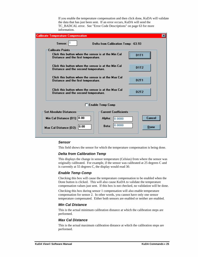
Overview Each KuDA in the system can be viewed through the KuDA Window. The KuDA Window contains data displays, control buttons and scroll bars.
Data Displays There are three data displays on the KuDA. These are: Function, Sensor 1 Output, Sensor 2 Output. The labels shown over each display can be changed for the specific application. For more on this see "Configuration" on page 11.
Function The user may specify an internal KuDA function whose output is displayed in the upper display on the KuDA Window. NOTE: This functionality will be included in a future release of KuDAView.

30 • The KuDA Window KuDA View© Software Manual
Sensor 1 Output The Engineering Unit output from Sensor 1 is output in the middle display of the KuDA Window. If using the three point Calibration, the sensor output will be displayed as a percent of full scale unless the sensor range has been changed. See "Sensor Ranges" on page 18 for information on changing the sensor range.
Sensor 2 Output The Engineering Unit output from Sensor 2 is output in the lower display of the KuDA Window. If using the three point Calibration, the sensor output will be displayed as a percent of full scale unless the sensor range has been changed. See "Sensor Ranges" on page 18 for information on changing the sensor range.

KuDA View© Software Manual The KuDA Window • 31
Control Buttons There are six buttons on the KuDA
Zero When the Zero button is clicked, the sensor readings are changed to zero. NOTE: Not supported in this Version.
Run/Stop This button performs two functions: When the button is in the Stop Mode, the button displays Run. Clicking on the button puts the KuDA in Run Mode. In Run Mode KuDA View continuously polls the KuDA for data. When the KuDA is in the Run Mode, the button displays Stop. Clicking on the button then stops KuDA View from polling the KuDA for data.
StripChart Clicking on the StripChart button causes a new chart to be created and displayed. The chart is initialized with default values which can be changed by using the chart’s menu. For more information on configuring charts see “Chart Commands” on page 33.
Close Clicking on the Close button causes the KuDA window to close. When the KuDA closes, KuDA View closes all charts associated with the KuDA. To open the KuDA again and view its data, you must either find it or connect to it. See "Find KuDA's" on page 5 and "Connect to KuDA" on page 5 for more information on re-opening KuDA's.
Configure This button performs the same function as the Configure menu command. See "Configuration" on page 11.
Calibrate This button performs the same function as the Calibrate menu command. The calibrate function is not supported in this version of KuDAView.

32 • The KuDA Window KuDA View© Software Manual
Display Labels Above and below each of the Data Displays are user configurable labels. The label above each display is intended to be used for indicting the function or parameter that is being measured (e.g. Rotor Distance). The label below each display is intended to be used to display the units of measurement (e.g. millimeters). KuDA View uses this text for display only and you can use these labels for other purposes as is appropriate. See "Configuration" on page 11 for more information.
Scroll Bars On the right and bottom sides of the KuDA Window are scroll bars that allow you to adjust the position of the KuDA inside the window. To change the position of the KuDA in the window, position the pointer over the slider and drag in the desired direction. To change the size of the KuDA window, position the pointer over the thick border that is around the KuDA window and drag to the desired size. If the KuDA is re-sized large enough, the scroll bars will disappear indicating that all of the KuDA window is visible.

KuDA View© Software Manual Chart Commands • 33
Chart Commands
Overview When a stripchart window is the Active window, KuDA View displays a different command menu, the Chart Menu. Each chart is capable of displaying three traces at once. For each trace, the data input to the trace can be selected as well as any analysis that is done to the data. The color of the trace can also be selected. This section describes the commands available from the Chart Menu.
Chart
Configure The Configure menu item opens a property dialog from which chart configuration settings can be edited or viewed. The dialog has five separate property sheets from which different settings can be configured.
Traces: Each chart has three traces which can be configured. Each trace tab is identical and displays information for the specific trace. You may configure the input data to the trace, the color, the type of data analysis performed and if the trace is to be shown.

34 • Chart Commands KuDA View© Software Manual
Trace Input This list box allows you to select which data the trace will display. Each trace can display a different input or each trace could be configured to display the same input, but with a different Data Analysis function. Also, if you only want to display one trace on the chart, two traces can be disabled.
Select Color This button will open a dialog box to let you select the color for the trace.
Show Trace The Show Trace check box controls display of the trace. If the box is checked the trace will be displayed on the chart. If it is not checked, this trace will not be displayed. In this way only one or two traces can be shown on a chart, if desired. When viewing the Cart Window, only traces that are displayed will have a legend shown.
Data Analysis Data Analysis provides a way to do statistical functions on the displayed data. For each sample set (see "General" on page 35), a peak, valley, average or standard deviation can be calculated and then displayed on the chart. Peak: Selects the greatest value of the sample set to be displayed. Valley: Selects the smallest value of the sample set to be displayed. Average: The samples in the value set are averaged and the result is displayed. Std. Dev.: The standard deviation of the sample set is displayed
Logging The Logging tab lets you specify the filename of the log file and if logging is enabled. If Data Analysis is selected, only the final data point will be written to the log file. For the log file fomat see "Log File Format" on page 41.

KuDA View© Software Manual Chart Commands • 35
Select File This control causes the Select File dialog box to be displayed from which the desired data log file can be selected. Data files, by default, have the .dat extension. Each chart can log data to only one file. If you need to have two separate log files, you can open another chart and log data from that chart also. If an existing file is selected, KuDA View will append the new data to that file. If another file is selected, open another chart and enable data logging for that chart also.
Log Data Checking this box enables data logging for this chart. This function is also provided on the Chart Window. See "Log Button" on page 38 for more information.
General The General tab allows changes to settings that effect all traces. This includes the number of samples in a sample set and whether data analysis is enabled.
Samples If Data Analysis is desired, the number of samples in the sample set is set here. For example, if 20 is entered here, each trace will accumulate 20 samples before performing the selected analysis function and plotting the result on the chart. Then, 20 more samples will be accumulated and so on. If analysis is desired, all shown traces on the chart will have analysis done to them before display. If some data is to be shown without analysis, open another chart to view that data in real time.
Enable Analysis In order for the analysis functions to be enabled, this box must be checked. If this box is not checked, then each sample will be displayed on the chart.
OK Clicking on the OK button will cause the currently displayed parameters to be saved.

36 • Chart Commands KuDA View© Software Manual
Cancel This button discards all changes and returns to the main KuDA View window.
Rescale The Rescale option causes the chart to be re-drawn using the current chart limits. This does the same thing as the Rescale button on the chart itself. See "Re-scale Button" on page 38 for more information.
Erase Choosing this menu option causes the active chart to be erased.
Close The Close menu option closes the active chart.
Window
Cascade This command re-arranges all of KuDAView’s open windows so that each title bar is visible to the user. Starting from the upper left-hand corner of KuDAView’s Main Window, the KuDA's and charts are offset toward the lower right-hand corner.
Tile The Tile command arranges the KuDA and chart windows like tiles so that all are visible and are not overlapped. The KuDA windows are re-sized to fit better on the screen.
Arrange Icons When the user minimizes KuDA's or charts they appear at the bottom of KuDA View main window as icons. The Arrange Icons command lines the icons up in straight lines.
Help Displays the Table of Contents for the Help System.
KuDA View© Software Manual The Chart Window • 37
The Chart Window
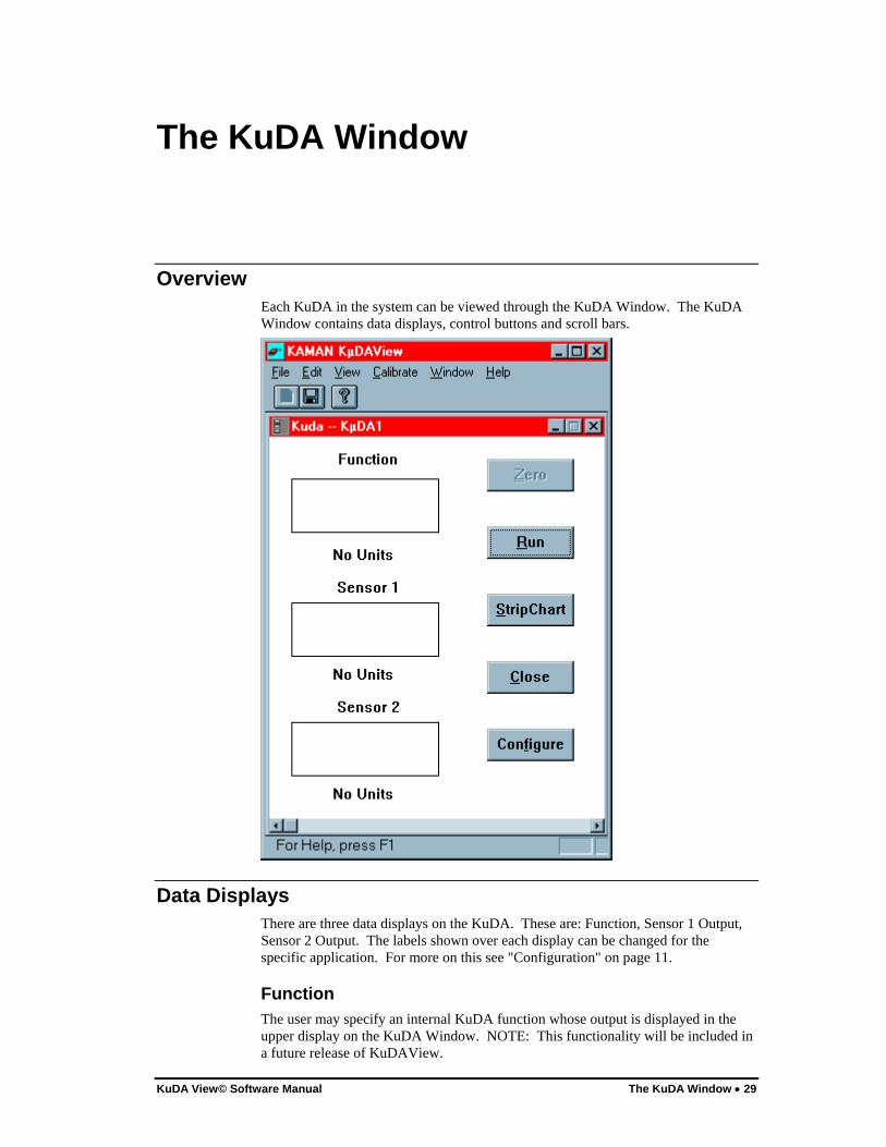
Overview The Chart Window contains a graphical representation of a stripchart. In addition, a legend, log button and display, re-scale button and axis limit edit boxes are visible in the window.
Chart The chart is where the data from the KuDA are displayed. Each chart can display up to three traces simultaneously.
Legend The Legend is shown to the left of the Chart. For each enabled trace, the name of the trace and the color of the trace are shown. The trace names cannot be edited here but can be changed through the KuDA Configuration Dialog box. See Configuration" on page 11 for more information. If Data Analysis has been enabled for this chart, the data analysis function will be indicated within the colored box in the legend. The codes are: A Average is displayed P Peak value is displayed V Valley is displayed S Standard Deviation is displayed If no letter is in the colored box, then the chart is displaying instantaneous data.

38 • The Chart Window KuDA View© Software Manual
Log Button The Log Button is the button with the "L" on it. It provides a way to turn logging on and off directly from the chart window. It performs the same function as the Log Data checkbox in the chart configuration dialog. Before logging data you must select a log file. See "Log Data" on page 35 for more information. Before each data value is written to the log file, the file is opened, the data value is written and the file is closed. In this way if a power outage causes a system crash, the last data gathered will still be in the log file. If an error occurs during data logging, make sure that another application does not have the file open or that (if logging to a floppy drive) the disk has not been removed.
Log Display The log display simply indicates to the user if logging is enabled or disabled.
Axis Limits The Axis Limits are the edit boxes at the corners of the chart. They enable you to scale the chart to meet your needs. To edit, first click on the desired limit and then use the editing keys to enter the desired value. If Enter is pressed, the chart will automatically be re-scaled to reflect the change. The minimum Y-axis value must be less than the maximum Y-axis value. The same is true for the X-axis values. Depending on the KuDA View sampling interval, some keystrokes in the Chart Window will be missed. To eliminate this problem, Stop the KuDA before making chart scaling changes and then re-start. See "Run/Stop" on page 31.
Re-scale Button The Re-scale Button is the button with the ''R" on it. After editing an axis limit, press the Re-scale Button to re-draw the chart with the new limits.
Right Mouse Button If the right mouse button is clicked while the arrow is over the chart window, the Chart menu will be displayed at that point. This provides a convenient way to enter the configuration dialog. See "Chart" on page 33 for more information.

KuDA View© Software Manual Communication Viewer • 39
Communication Viewer
Overview The Communications Viewer is a separate window through which communication between KuDA View and the KuDA(s) can be viewed. The Communications Viewer can be used as a dumb terminal in both RS-232 and RS-485 modes. In RS-485 mode you must add the address string to the front of the command. During normal operation this window does not need to be used and can be minimized to free screen space for other windows. Although the Communications Viewer has the standard windows buttons and system menu, the window cannot be closed, only minimized.
Menu File|Copy The Copy command is used to copy text to the clipboard for pasting into other applications. To copy text, first select the text by clicking and dragging. Then select File|Copy. The selected text is now in the clipboard for pasting.
Help Displays the KuDA View About box.


KuDA View© Software Manual Log File Format • 41
Log File Format
Description When data logging (see "Logging" on page 34) has been enabled a data file will be written to a specified directory. This data file can be imported into a spreadsheet using comma delimited format. The spreadsheet can then be used to chart and otherwise analyze the data.
Example 1 This shows a few lines from a log file. When the data was logged the chart had the following settings: Trace 1 Function Average Trace 2 Sensor 1 Average Trace 3 Sensor 2 Average Note the header written at the top of the data. Each time logging is turned off and then turned back on, KuDA View writes a new header line in case sampling conditions have changed. The 10 at the end of the header line was the size of the sample set. Date,Time,Function-Average,Sensor 1-Average,Sensor 2-Average,10 02/14/97,17:39:34,36.742500,51.414001,48.569000 02/14/97,17:39:52,36.737000,51.412998,48.580502 02/14/97,17:40:10,36.720501,51.414501,48.583000 02/14/97,17:40:28,36.713501,51.418499,48.590000
Example 2 In this log file the chart had the following settings: Trace 1 Function Average Trace 2 Function Peak Trace 3 Function Valley Note the second header line when logging was turned off and then back on. Also note that the name of the function was changed from function to Widgets (see on page 11). Date,Time,Function-Average,Function-Peak,Function-Valley,20 02/19/97,10:09:53,29.667999,29.680000,29.660000 02/19/97,10:09:59,36.131001,40.349998,29.299999 02/19/97,10:10:06,36.299999,40.700001,29.170000 02/19/97,10:10:12,38.000000,41.000000,29.110001 02/19/97,10:10:18,36.958000,40.840000,29.320000 02/19/97,10:10:24,31.788000,40.709999,29.160000 02/19/97,10:10:30,40.070999,41.000000,38.759998

42 • Log File Format KuDA View© Software Manual
02/19/97,10:10:36,36.537998,40.869999,29.110001 Date,Time,Widgets-Average,Widgets-Peak,Widgets-Valley 02/19/97,10:10:57,40.821999,40.900002,40.299999 02/19/97,10:11:03,40.500000,40.910000,40.160000 02/19/97,10:11:09,38.386002,40.930000,29.100000
Example 3 In this log file the chart had the following settings: Trace 1 Function Average Trace 2 Disabled Trace 3 Sensor 2 Average Date,Time,Function-Average,Sensor 2-Average,20 02/19/97,11:13:03,29.53,34.35 02/19/97,11:13:42,29.52,34.36

KuDA View© Software Manual Editing KuDAView.INI • 43
Editing KuDAView.INI
Description When KuDA View first loads, it reads an initialization file named KUDAVIEW.INI that resides in the Windows subdirectory. This file contains system settings that KuDA View uses to configure itself. This section describes the settings and possible entries for each. After editing KUDAVIEW.INI KuDA View must be restarted in order for the changes to take effect. Do not attempt to edit this file unless directed by Kaman Technical Support to do so or you really know what you are doing. A typical .INI file is shown below: [LastSetupFile] SetupFile=G:\STAN\8500\WIDE.SET [Parameters] CalPoints=21 ExtSearch=0 Profile=TIMCAN Interval=750 User=Authorized User Company=Kaman Instrumentation [InitStrings] DefStr1=M1C0 DefStr2= DefStr3= DefStr4= DefStr5= DefStr6= DefStr7= DefStr8= [Settings] DefaultFile=c:\kudainst\kuda.dwn EnableMenus=0 EnableCS=1

44 • Editing KuDAView.INI KuDA View© Software Manual
[Setup Files] SetupFile1=G:\SETUP\1001.SET SetupFile2=G:\SETUP\5206.SET SetupFile3= SetupFile4= SetupFile5= SetupFile6=
LastSetupFile This section contains the complete path to the last setup file used. This file will be loaded on startup.
Parameters CalPoints The number of calibration points used for a cal. Don't change this value.
ExtSearch Determines the maximum number of addresses to search.
Profile Proprietary
Interval The time in milli-seconds between polls. Because a new poll cannot be started until the last one has finished, there is a minimum pratical interval setting. In most siturations an interval of 700 to 1000 milliseconds will work.
User The User Name entered during setup.
Company The Company Name entered during setup.
InitStrings These are the strings that are sent with the initialize KuDA command. See "Initialize KuDA" on page 12 for more information.
Settings DefaultFile The default file for downloading to Kuda.
EnableMenus Not used
EnableCS A value of 1 means that a check sum will be added to the end of all communications with the KuDA. A zero disables the checksum feature.
KuDA View© Software Manual Editing KuDAView.INI • 45
Setup Files These are the files configured by the AutoSetup function. See "AutoSetup" on page 13 for more information.


KuDA View© Software Manual Communicating with KuDA Soft • 47
Communicating with KuDA Soft
Caution: The improper use of these commands could lead to the corruption of the KuDA's operating parameters and require that the KuDA be sent to the factory for recalibration or temperature compensation. Other commands (besides the ones explained here) are present in the KuDA Soft command set and are reserved for the exclusive use of factory personnel. Thus, the sending of random character sequences could inadvertantly invoke one of these commands causing unintended results. The checksum should always be used to increase data integrity and minimize the chance of misinterpreted command sequences.
Conventions:
<CR> stands for the Carriage Return character, ASCII 0x0D. <space> stands for the space character, ASCII 0x20. <addr> stands for the KuDA's address.
The KuDA Address:
Each KuDA has a unique address. If communicating in RS-232 mode, no address needs to be sent. If communicating in RS-485 mode the command is preceded by a $ (ASCII 0x24) and <addr>. For ease of use, the KuDA's should be numbered sequentially starting at 1.
The KuDA Soft Prompt:
The prompt is sent at the end of every response that the KuDA makes and is not followed by a <CR>. This does not have to be entered as part of the command string. The prompt contains the current Command Mode followed by the > character (ASCII 0x3E). For example, if the current command mode is Mode 1 the prompt would appear as: 1> To change the Command Mode, enter M<mode> where <mode> is the desired mode. For example, if you want to change from Mode 0 to Mode 1:
0> M1<CR>

48 • Communicating with KuDA Soft KuDA View© Software Manual
1>
In the command string descriptions that follow, the KuDA Soft prompt is printed in bold: 0>
Communication Modes:
You can communicate with the KuDA in either RS-485 or RS-232 mode. For information on how to connect the KuDA in these modes, see the KuDA Hardware Manual.
Command Strings:
RS-232: When communicating in RS-232 mode, only the command string (and checksum if desired) needs to be sent. For example:
0> M0D3<CR> RS-485: When communicating in RS-485 mode, the command (and checksum if desired) is preceded by the address. For example, if communicating to address 1:
0> $1M0D3<CR>
The Checksum:
To enhance data integrity, KuDA Soft has a checksum feature. If KuDA Soft receives a command string that has a checksum appended to it, then it will validate the checksum that was sent and return a checksum appended to the data requested. If KuDA Soft receives a command that has no checksum, then it will not send one. If KuDA Soft receives a command string that has an incorrect checksum, it sends a ?BAD_CHKSUM error message. KuDA Soft is then ready to receive the next command string. The checksum is the modulo 256 sum of the ASCII values of the characters in the command string. It iss appended to the command string separated by a # character (ASCII 0x24). If in RS-485 mode, the $<addr> is not used in computing the checksum. For example the checksum for the command string M0D3 would be calculated as follows:
RS-232 mode:
Character ASCII Value
M 0x4D
0 0x30
D 0x44
3 0x33

KuDA View© Software Manual Communicating with KuDA Soft • 49
Checksum 0xF4
The full string sent to KuDA Soft would be M0D3#F4<CR>. RS-485 mode <addr>=1:
Character ASCII Value
$ 0x00
1 0x00
M 0x4D
0 0x30
D 0x44
3 0x33
Checksum 0xF4
The full string sent to KuDA Soft would be $1M0D3#F4<CR>. Note that the $1 was not used in the checksum calculation. In both modes, after receiving the command string, KuDA Soft will respond with the desired data, appending a checksum in the same manner as the checksum that was sent. For example: 53.01 47.26 10.00#27<CR> 0> Note that there is no checksum sent after the prompt. All characters in the response are used to calculate the checksum, including spaces, commas and decimal points.
Commonly Used Commands: Note: All commands are terminated with a <CR>. The commands below assume that the KuDA is in RS-232 mode. Use the information above to convert to a RS-485 command string.
Mode 0 Commands:
Get Data Outputs the scaled data for the desired sensor or function. Syntax: 0> D<data> <data>: 0 Sensor 1

50 • Communicating with KuDA Soft KuDA View© Software Manual
1 Sensor 2 2 Reserved 3 Sensor 1, 2 and Function Output Format: D0: XX.XX<CR> D1: XX.XX<CR> D3: XX.XX<space>XX.XX<space>XX.XX<CR>
Mode 1 Commands: For more on addresses see "KuDA Address" on page 66 or "Connect to KuDA" on page 5.
Get RS485 Address
Syntax: 1> A Prints out the current RS485 Address
Set RS485 Address
Syntax: 1> S<address> <address>:
value of address
Mode 2 Commands: For more information on scaling see "Sensor Ranges" on page 18.
Scale Engineering Units
Syntax: 2> S<chan>,<lolim>,<hilim> <chan>:
Sensor number (0 or 1)

KuDA View© Software Manual Communicating with KuDA Soft • 51
<lolim>:
floating point value representing the offset value at which the sensor was calibrated.
<hilim>:
floating point value representing the full scale value plus the offset value at which the sensor was calibrated
Mode 4 Commands: For more information on limits see "KuDA Limits" on page 19.
Input Setting
Indicates which input source the limit will use as its input Syntax: 4> I<lim>,<source> <lim>: Limit number to be configured 1-4 <source>: The data source to be used for this limit Sensor 1 0 Sensor 2 1 Thickness 4 Reserved 2, 3, 5-254 No Source 255
Limit Direction
Sets the direction of the limit in the Active state Syntax: 4> D<lim>,<direction> <lim>: Limit number to be configured 1-4 <direction>: Active High 1

52 • Communicating with KuDA Soft KuDA View© Software Manual
Active Low 0
Limit Enable
Enables or Disables limit outputs Syntax: 4> E<lim>,<state> <lim>:
Limit number to be configured 1-4 <state>: Limit Enabled 1 Limit Disabled 0
Limit Setting
Syntax: 4> S<lim>,<high limit>,<low limit> <lim>:
Limit number to be configured 1-4 <high limit>:
The upper trip value in calibration units. <low limit>:
The lower trip value in calibration units.
Set Limit Type
Sets the type of limit Syntax: 4> T<lim>,<type> <lim>: Limit number to be configured 1-4

KuDA View© Software Manual Communicating with KuDA Soft • 53
<type>: Hi/Low w/Hysterisis 1 Window 0
Mode 5 Commands: For more information on Output Voltage see "Other Parameters" on page 16.
The voltage outputs are calibrated by using the following procedure:
1. Attach a voltmeter to the output to be calibrated. 2. Use the C command to cause the KuDA to go its high and low
reference values. Record these values. 3. Use the S command to enter the values read in the previous step. 4. Verify the output range by using the D command.
Output Calibration Syntax: 5> C<chan>
DAC <chan>
A 0 B 1 C 2
Causes the Voltage outputs to first go to the current minus reference and then to the current high reference. These values are recorded by the user and entered in the "S" command below.
Output Calibration View
Syntax:
5> D<chan>
DAC <chan> A 0 B 1 C 2

54 • Communicating with KuDA Soft KuDA View© Software Manual
Causes the two calibration values to be sent to the DAC. The DAC outputs should go exactly to the desired minus reference and plus reference.
Set Output Scaling
Syntax:
5> S<chan>,<minusref>,<plusref>
DAC <chan> Vout1 0 Vout2 1 Vout3 2 <minusref>:
floating point value recorded using the "C" command above
<plusref>: floating point value recorded using the "C" command above
This command causes two calibration values to be calculated. These values are the actual output values to cause the outputs to go exactly to the vref limits. They can be checked by using the "D" command above.
Mode 6 Commands: For more information on Thickness Setup see "Thickness Setup" on page 14.
Calibrate
Syntax: 6> S To use this command, first place the calibration standard thickness between the two sensors. When this command is issued, KµDA will adjust its output to read the thickness entered with the C command above. This command does the same thing as pressing the User Function 1 button.
Enable Thickness Output
Syntax: 6> E<state>
<state>:

KuDA View© Software Manual Communicating with KuDA Soft • 55
Enable Thickness Output 1 Disable Thickness Output 0
When this command is issued, the system will check to make sure that the two sensors have been scaled the same and that valid calibrations exist on both sensors. Error 23, FN_INVALID will be displayed if there is a problem. Note: This command must be issued after any change in the thickness setup in order for the changes to take effect.
Calibration Standard
Syntax: 6> C<thickness> <thickness>:
floating point thickness of the object used for calibration. This should be in the same units to which the sensors were scaled.
Set Output Range
Syntax: 6> R<low>,<high> <low>:
floating point low voltage. When the thickness is at this value the voltage output will be at the low voltage reference set in Mode 9. This should be in the same units to which the sensors were scaled.
<high>:
floating point high voltage. When the thickness is at this value the voltage output will be at the high voltage reference set in Mode 9. This should be in the same units to which the sensors were scaled.
Mode 7 Commands: For more information on Temperature Compensation see "Temp Comp Sensor 1" on page 24.
Done
Syntax: 7> D<chan>

56 • Communicating with KuDA Soft KuDA View© Software Manual
<chan>: Sensor 1 0 Sensor 2 1
This command is issued after the points and absolute distances have been set. It calculates coefficients and saves the parameters in flash. Use the Mode 9 "U" command to enable temp comp.
Set Absolute Distances
Syntax: 7> C<chan>,<dist 1>,<dist 2> <chan>: Sensor 1 0 Sensor 2 1 <dist 1>: Absolute distance for Temperature Calibration Point 1 <dist 2>: Absolute distance for Temperature Calibration Point 2
Set Point
Syntax: 7> P<chan>,<point> <chan>: Sensor 1 0 Sensor 2 1 <point>: Min distance, Min temperature 1 Min distance, Max temperature 2 Max distance, Min temperature 3 Max distance, Max temperature 4
Set Raw Temp Comp Data
Syntax:
7> R<chan>,<d1t1>,<d1t2>,<d2t1>,<d2t2>,<t1d1>,<t1d2>,<t2d1><t2d2> <chan>: Sensor 1 0 Sensor 2 1 <xxxx>:
Raw temp comp values by the same name

KuDA View© Software Manual Communicating with KuDA Soft • 57
Mode 9 Commands:
Burn Flash Stores the current setup parameters into non-volatile memory
Syntax: 9> B
Counter Commands
Divide 18 MHz by the number entered here to obtain the oscillator frequency for the given sensor. Syntax: 9> N<chan>,<counts> <chan>: Sensor 1 0 Sensor 2 1 <counts>: number between 0 and 255
DAC Scaling Commands
Sets the DAC max and min value. Syntax: 9> V<Vminus>,<Vplus> <Vminus>: Floating point number between 0 and 10 (do not include "-" sign) <Vplus>: Floating point number between 0 and 10
Filter Setting Sets the alpha parameter in the filtering equation: Output = (1-alpha)(Last Output) + alpha(New Reading) Syntax: 9> E<mode>

58 • Communicating with KuDA Soft KuDA View© Software Manual
<mode>: alpha = 1 / 2^<mode> mode = 0 turns filtering off
High Speed A/D Commands Displays the most recent data from the High Speed A/D
Syntax: 9> H<chan>
<chan>: Data Sensor 1 0 Data Sensor 2 1 Output: A/D Reading, <raw>,<linear> where <raw> is the raw counts from the High Speed A/D and where <linear> is the linearized output to D/A
High Speed A/D Statistics
Displays statistics about High Speed A/D reading. Make sure that the Debug output has been enabled. See the M9Z command. Syntax:
9> G<chan>,<numpts> <chan>:
Sensor 1 no dump w/stats 0 Sensor 2 no dump w/stats 1 Sensor 1 dump w/o stats 2 Sensor 2 dump w/o stats 3 <numpts>: number of points for analysis Output: <raw mean> ,<raw std> ,<raw peak>,<raw valley>,<lin mean> ,<lin std> ,<lin peak>,<lin valley>
where <raw mean> is the mean of the raw samples <raw std> is the raw standard deviation <raw peak> is the highest value in the raw sample set
<raw valley> is the lowest value in the raw sample set <lin mean> is the mean of the linear samples <lin std> is the linear standard deviation <lin peak> is the highest value in the linear sample set
<lin valley> is the lowest value in the linear sample set

KuDA View© Software Manual Communicating with KuDA Soft • 59
Keys Off
Syntax: 9> K<state> <state>: Keys Off 1 Keys On 0
List Command
Lists System Parameters Syntax: 9> ?
Low Speed A/D Commands
Ouputs the scaled value and raw counts for the low speed A/D channels Syntax: 9> A<A/D chan> <A/D chan>: Factory Cal 1 Sensor 1 0 Factory Cal 2 low Sensor 1 1 Factory Cal 1 high Sensor 2 2 Factory Cal 2 low Sensor 2 3 Board Temperature 4 General Power Status 5 None 6 None 7 Minus 12 Supply 8 Ramdac Test A 9 Ramdac Test B 10 None 11 DAC1 Current 12 DAC2 Current 13 DAC3 Current 14 Five Volt Supply 15 Note: If <A/D chan> is greater than 15 then all channels will be output.
Repeat Last Command
Repeats the last command entered. Syntax:

60 • Communicating with KuDA Soft KuDA View© Software Manual
9> ^
Sampling Frequency Syntax: 9> F<freq> <freq>: Sampling Frequency in Hz
Sensor Temperature Displays relative sensor temperature
Syntax: 9> T<chan>
<chan>:
Sensor 1 0 Sensor 2 1
TempComp Enable Enables or disables temperature compensation
Syntax: 9> U<state> <state>: TC Disabled 0 TC Enabled 1
Toggle Debug Mode Toggles the debug output ON or OFF
Syntax: 9> Z
Warm-up Test Syntax: 9> W<channel> <channel>: Sensor 1 0

KuDA View© Software Manual Communicating with KuDA Soft • 61
Sensor 2 1 Output: <Raw Counts>,<Lin Counts>,<Board Temp>,<Delta Sensor Temp>


KuDA View© Software Manual Error Messages • 63
Error Messages
Error Code Descriptions In the event of an error being displayed, the table below can be used to find and possibly correct the error. Many of the errors below are hardware problems within the KuDA itself. Call Kaman Technical Support if you are unsure as to the remedy to the problem. Note: Some errors are displayed through the serial port only. The format of the error is, ?<ERROR STRING>:<PARAMETER>
ERROR STRING DISPLAYED ON KEYPAD
PARAMETER DESCRIPTION
N0_PROMPT N/A N/A The KuDA did not respond to the command. Check to make sure that the serial cable is firmly plugged in.
SB_SERIAL 0 Always zero Error communicating with Measuring Channel Boards. This indicates a hardware failure.
SB_CP 1 Always zero Error configuring internal components. SB_CS 2 Always zero Error configuring internal components. SER_OV 3 Always zero Serial Communications Buffer Overflow. This error is
generated when the command sent to the Kuda exceeds 32 characters.
CMD_BAD 4 Always zero Illegal Command. The command string that was sent to KuDA contained a command which was not recognized. This can also happen if the serial cable is loose or intermittent.
KP_SWITCH 5 Keypad switch state
Error reading keypad.
BAD_CAL 6 Always zero Bad calibration. When a calibration is finished, KuDA checks to see if the values sent were valid. If KuDA detects an error, BAD_CAL is sent.
RAMDACA_VLT 7 A/D reading Error Reading Ramdac A Voltage. RAMDACB_VLT 10 A/D reading Error Reading Ramdac B Voltage. FX_WRTERR 11 Error writing Flash Memory. SB_NONE 12 Always zero No sensor boards detected. CAL_INPROGRESS 13 Always zero Cal is in Progress. Quit the current calibration and start
over. CAL_OR 14 Point or sensor
number Error in Calibration.
CAL_BADCHANNEL 15 Channel Number Illegal channel entered during cal. LS_CALTO1 16 Always zero Low Speed A/D time-out. SB_NOSEN1 17 Always zero No Sensor Detected on Channel 1. Connect a sensor to
this channel to eliminate the error message. QSPI_TO 20 Always zero QSPI Time-out. SB_NOSEN2 21 Always zero No Sensor Detected on Channel 2. Connect a sensor to
this channel to eliminate the error message. TC_BADCAL 22 Sensor number Bad Temperature Calibration. Make sure the two
temperatures are not the same and that the values of D1

64 • Error Messages KuDA View© Software Manual
and D2 are different. FN_INVALID 23 Always zero Error During Function Initialization. For thickness, the
Cal standard must be between the high and low output limits and cannot be negative. Also the sensors must be calibrated over the same range to enable thickness outputs. See "Sensor Ranges" on page 18 for more information.
RD_A_MEM 24 Error location and value
Error Writing to Internal Memory.
RD_B_MEM 25 Error location and value
Error Writing to Internal Memory.
NOMEM 26 Number of bytes
System Error Allocating Memory.
NOT_COMPAT 27 Always zero The KuDA has detected that a non-compatible version of KuDA View is being used. Download KUDA.DWN from the installation directory.
BAD_CHKSUM 30 Always zero A bad checksum was detected FLSH_F2R 31 Memory
address Error transferring flash memory to RAM
FLSH_R2F 32 Memory address
Error transferring RAM contents to flash memory
LS_CALTO2 33 Always zero Error during low speed A/D full calibration LS_CALTO3 34 Always zero Error during low speed Auto Zero PWRSTATUS 35 A/D reading Error during power status check PWRMINUS12 36 A/D reading Error during -12V power check PWRPLUS5 37 A/D reading Error during +5V power check PWRREF5 40 A/D reading Error during +5V reference check FX_VALID 41 Addr of Bad
Flag Error validating data before burn
SB_TOFF1 42 A/D reading Internal Error

KuDA View© Software Manual Glossary of Terms • 65
Glossary of Terms
Active KuDA The KuDA that is displayed in the Active Window.
Active Window The window that is currently receiving input. The Active Window will have a dark title bar while all other windows will have a lighter title bar.
Calibration The process of making KuDA read correctly throughout a measurement range.
Click The process of depressing the left mouse button and then releasing it.
Close Window: Making a window so that it is not visible and has no functionality
Communications Viewer A KuDA View window that can be used to interactively communicate with a KuDA in either RS-232 or RS-485 mode. It can be opened using the View|Comm Viewer menu command.
Counts An integer output by an A/D converter that represents the voltage present on its input.
Dialog A dialog or dialog box is a window which lets the user enter, change or view information about the system. Dialogs are typically temporary and disappear after they are not needed.
Download The process of transferring a new version of KuDASoft from a file on the PC's disk to the non-volatile memory in the KuDA itself.
Drag The process of pressing the left mouse button and moving the mouse at the same time. Usually used to move objects on the screen.

66 • Glossary of Terms KuDA View© Software Manual
Dumb Terminal A window through which a user can communicate interactively with a KuDA by typing commands that the KuDA understands and receiving information from the KuDA.
Edit Field A box into which text is typed and edited.
Enabled, button When a button is enabled the text on the button is dark. If it is not enabled, the text will appear gray. Only enabled buttons can be pressed.
File Extension The part of the filename that is to the right of the period. Only three characters are allowed for a file extension.
Filter A low-pass filter removes noise and high frequency components from a signal producing a more stable and repeatable reading.
Function Keys The "F" keys at the top of a typical IBM compatible keyboard.
Grayed An item that is shown in grayed text is disabled an cannot be selected. This is done to prevent certain functions from being used in some situations.
Icon A picture that is used to represent a program or window. KuDA View uses an icon to represent a minimized window.
KuDA Address Each KuDA in the thickness measuring system has a unique address that KuDA View uses to communicate with it.
KuDA Window A window that displays the data and controls for a thickness KuDA. You can have one and only one KuDA window for every KuDA in the system.
KuDASoft The embedded software program which is resident inside the KuDA itself. The user communicates with KuDASoft by using the functions in KuDA View.
KuDAView A computer program used to communicate with a KuDA measuring system.
Linearity The measure of how closely a measurement system performs over its measurement range

KuDA View© Software Manual Glossary of Terms • 67
Loader Mode A mode of KuDA operation in which the KuDA is ready to accept a new revision of software. The Loader Mode can be entered by depressing the Calibrate/Run switch on the front panel and cycling power.
Log The act of saving data read from the KuDA into a file on the PC's hard disk.
Minimized A window that has been reduced to its iconic state.
RS-232 A method of full-duplex data communication that typically is used to link only two devices. KuDA View only supports one KuDA in RS-232 mode.
RS-485 A method of data communication that uses two wires and allows the communication devices to be connected in parallel.
Serial Port A connector on the back of a computer through which RS-232 communications can take place.
Setup Files A file, stored on hard disk, that saves a snapshot of KuDAView’s configuration at the time it was saved. Information about window size and position, color and other configuration is stored in this file.
StripChart Window A window that contains a stripchart which is used for viewing data trends. The stripchart has its own unique menu.
Temp Comp The act of compensating the sensor output for changes in temperature.
Title Bar The section at the top of a window that displays the window's title or name.
Toolbar The Toolbar is a series of buttons directly below the menu bar. These buttons let you perform frequently used functions without having to go through the menu commands.
68 • Index KuDA View© Software Manual
Index
—A—
About, 23, 28, 39, 58 Advanced, 12–13 AutoSetup, 13, 45
—C—
Cal Standard, 14, 64 Cascade, 27, 36–38 counts, 16, 57–59, 61
—D—
data analysis, 33–35, 37 data logging, 35, 38, 41 dialog, 2, 5–13, 18–19, 26, 33–
35, 37–38 Display Labels, 32 download, 3–4, 8–9, 6, 8–9, 8–
9, 8–9, 64 Dumb Terminal, 39
—E—
Enable Temp Comp, 25, 56 Enabled, 12–13, 15, 17, 21, 25,
34–35, 37–38, 41, 52, 58, 60
Error Messages, 63
—F—
Filter Mode, 17 Flash Erase, 9
—H—
help, 1, 6, 23, 28, 36, 39 High Reference, 17, 53 High Setting, 21–22
—I—
Initialize, 12, 44 Install, 2 Interface Converter, 1
—K—
Keys Off, 18, 59
KuDA Window, 5, 11, 18, 29–32
KuDASoft, 8–9, 15
—L—
Limits, 19, 36, 38, 51, 54, 64 Low Reference, 17, 53 Low Setting, 20–22
—M—
manually update, 3 Max Cal Distance, 24, 26 Min Cal Distance, 24, 26
—P—
Password, 12–13
—S—
Sample Rate, 17 Sensor 1 Frequency, 17 setup, 1–2, 6–9, 13–14, 6–9, 18,
23, 6–9, 44–45, 54–55, 57 setup program, 2, 9 Starting KuDAView, 2, 9, 10 startup, 2, 44 Status Bar, 23
—T—
Temperature Compensation, 17, 24–26, 47, 56, 60
Thickness Setup, 14, 54–55, 54 three point calibration, 16, 18–
19, 26, 30 Tile, 28, 36 Toolbar, 22 twenty-one point, 16, 26
—V—
V3 OUT, 14 value, 14, 16, 19, 21–22, 26, 34,
37–38, 44–45, 48, 50–52, 54–55, 57, 59, 64
View Menu, 22

KuDA View© Software Manual Index • 69