Embed Size (px)
Citation preview

Software Logistics
Planning Handbook
October 1995
MR. JOSEPH J. POTOCZNIAKDSN 992-1380
COM’L (908) 532-1380FAX (908) 532-4960
e-mail: [email protected]

2

SOFTWARE
LOGISTICS
PLANNING
HANDBOOK
OCTOBER 1995

i
SOFTWARE LOGISTICS PLANNING HANDBOOK TABLE OF CONTENTS
SECTION TITLE PAGE CHAPTER 1. INTRODUCTION 1 1.1. INTRODUCTION 1 1.1.1 Objective 1 1.1.2 Applicability 1 1.1.3 Responsibilities 1 1.1.4 References 2 1.2 PRE-PROGRAM INITIATION PERIOD 2 1.3 CONCEPT EXPLORATION AND DEFINITION PHASE 3 1.3.1 CED Phase Computer Resource Support Activities 4 1.3.2 CED Phase Documentation 4 1.4 CONCEPT DEMONSTRATION AND VALIDATION PHASE 5 1.4.1 CDV Phase Computer Resource Support Activities 5 1.4.2 CDV Phase Documentation 5 1.5 ENGINEERING AND MANUFACTURING PHASE 6 1.5.1 EMD Phase Computer Resources Support Activities 6 1.5.2 EMD Phase Documentation 7 1.6 PRODUCTION AND DEPLOYMENT PHASE 7 1.6.1 PD Phase Computer Support Activities 7 1.6.2 PD Phase Documentation 8 1.7 OPERATIONS AND SUPPORT PHASE 8 1.7.1 OS Phase Computer Resources Support Activities 8 1.7.2 Problem Resolution 9 1.7.3 OS Phase Documentation 9 CHAPTER 2. MODEL COMPUTER RESOURCES SUPPORT SECTION of the INTEGRATED LOGISTIC SUPPORT PLAN 31 2.0 GENERAL 31 2.0.1 Integrated Logistic Support Plan 31 2.0.2 Computer Resources Support Section of the ILSP 31 2.0.3 Computer Resources Life-Cycle Management Plan 32

ii
SECTION TITLE PAGE 2.1 COMPUTER RESOURCES SUPPORT (2.6.8) 32 2.1.1 Scope (2.6.8.1) 32 2.1.1.1 Computer Resources 32 2.1.2 Computer Resources Acquisition Methodology (2.6.8.2) 33 2.1.3 Computer Resources Support Concept (2.6.8.3) 33 2.1.3.1 The Pre-deployment Computer Resources Software Support Concept 35 2.1.3.2 Transitional Computer Resources Software Support 36 2.1.3.3 Post Deployment Software Support Concept 37 2.1.4 Computer Resources Support Strategy (2.6.8.4) 37 2.1.4.1 CRSS - Concept Exploration/Definition Phase 37 2.1.4.2 CRSS - Concept Demonstration/Validation Phase 39 2.1.4.3 CRSS - Engineering and Manufacturing Development Phase 40 2.1.4.4 CRSS - Production and Deployment Phase 42 2.1.4.5 CRSS - Operation and Support Phase 43 2.1.5 Computer Resources Support Policies, Procedures and Practices (2.6.8.5) 43 2.1.6 Computer Resources Support Program (2.6.8.6) 44 2.1.6.1 Concepts Exploration/Definition Phase 44 2.1.6.2 Concept Demonstration and Validation Phase 45 2.1.6.3 Engineering and Manufacturing Development Phase 46 2.1.6.4 Production and Deployment Phase 46 2.1.7 Organizations with ILS Responsibilities for Computer Resources Support (2.6.8.7) 46 2.1.7.1 Combat Developer 47 2.1.7.2 Materiel Developer 47 2.1.7.3 Readiness Command 47 2.1.7.4 Software Engineering Directorate 48 2.1.7.5 Software Support Activity 49 2.1.7.6 Computer Resources Working Group 49 2.1.8 Computer Resources Integrated Logistic Support Requirements (2.6.8.8) 49 2.1.8.1 Operational Requirements 50 2.1.8.2 Maintenance Requirements 51 2.1.8.3 Computer Resources Limitations 52 2.1.8.4 Security Requirements and Controls 53 2.1.9 Software Documentation (2.6.8.9) 53 2.1.10 Software Support Environments (2.6.8.10) 54 CHAPTER 3. MODEL LIFE CYCLE SUPPORT SECTION of the COMPUTER RESOURCES LIFE-CYCLE MANAGEMENT PLAN 57

iii
3.0 INTRODUCTION 57 SECTION TITLE PAGE 3.0.1 Computer Resources Life-Cycle Management Plan 57 3.0.2 Applicability 57 3.0.3 Organization of the Computer resources Life-Cycle Management Plan 57 3.1 GENERAL (SECTION I) 57 3.1.1 Introduction (I.A) 58 3.1.2 System CRLCMP Maintenance (I.B) 58 3.1.3 Applicable Documents (I.C) 58 3.1.4 Definitions (I.D) 58 3.1.5 Acronyms and Abbreviations (I.E) 58 3.1.6 System Description (I.F) 58 3.1.7 Computer Resources Issues (I.G) 58 3.1.8 Participating Organizations and Working Groups (I.H) 58 3.1.8.1 Software Engineering Directorate 58 3.1.8.1.1 SED Management Support 58 3.1.8.1.2 SED Technical Support 59 3.1.8.1.3 SED Post Deployment Support 59 3.2 ACQUISITION AND DEVELOPMENT (SECTION II) 60 3.2.1 Computer Resources Acquisition Strategy (II.A) 60 3.2.2 Program Schedules and Funding (II.B) 60 3.2.3 Computer Resources (II.C) 60 3.2.3.1 Target Computer System(s) (II.C.1) 61 3.2.3.2 Elements of the Developmental Software Support Environment (II.C.2) 61 3.2.3.3 Life Cycle Software Support Environment (II.C.3) 61 3.2.4 Standardization and Commonality and Reusability (II.D) 61 3.2.5 Software Metrics (II.E) 61 3.2.6 Risk Management (II.F) 61 3.2.7 Design Methodology (II.G) 62 3.2.8 Throughput and Reserve Margins (II.H) 62 3.2.9 Risk Identification (II.I) 62 3.2.10 Security and Virus Protection (II.J) 62 3.3 ASSESSMENT (SECTION III) 62 3.3.1 Test Requirements (III.A) 62 3.3.2 Total Quality Management (III.B) 62 3.4 LIFE CYCLE SUPPORT (SECTION IV) 62 3.4.1 Participating Organizations (IV.A) 63 3.4.2 Software Configuration Management (IV.B) 63 3.4.3 Management Responsibility Transfer (IV.C) 63 3.4.4 Documentation (IV.D) 63

iv
SECTION TITLE PAGE 3.4.5 Special Support Resources Required (IV.E) 63 CHAPTER 4. MODEL SOFTWARE TRANSITION PLAN 65 4.0 OVERVIEW 65 4.0.1 Software Transition Plan 65 4.0.2 Organization of the Software Transition Plan 65 4.0.3 Software Transition Plan Data Item Description 65 4.1 SCOPE (1) 66 4.1.1 Identification (1.1) 66 4.1.2 System Overview (1.2) 66 4.1.3 Document Overviews (1.3) 66 4.1.4 Relationship to Other Plans (1.4) 66 4.2 REFERENCED DOCUMENTS (2) 66 4.3 SOFTWARE SUPPORT RESOURCES (3) 66 4.3.1 Facilities (3.1) 66 4.3.2 Hardware (3.2) 67 4.3.3 Software (3.3) 67 4.3.4 Other Documentation (3.4) 68 4.3.5 Personnel (3.5) 68 4.3.6 Other Resources (3.6) 68 4.3.7 Interrelationships of Components (3.7) 68 4.4 RECOMMENDED PROCEDURES (4) 69 4.5 TRAINING (5) 69 4.6 ANTICIPATED AREAS of CHANGE (6.) 69 4.7 TRANSITION PLANNING (7) 69 4.8 NOTES (8) 70 CHAPTER 5. MODEL COMPUTER RESOURCES SUPPORT SECTION of the MATERIEL FIELDING PLAN 71 5.0. GENERAL 71 5.0.1 Materiel Fielding Plan 71 5.0.2 Organization of the Materiel Fielding Plan 71 5.1. INTRODUCTION (SECTION 1) 71

v
SECTION TITLE PAGE 5.1.1 Purpose (1.1) 71 5.1.2 Data (1.2) 71 5.1.3 Agreements (1.3) 72 5.1.4 Fielding and Logistical Support Concept (1.4) 72 5.2 SYSTEM DESCRIPTION (SECTION 2) 72 5.2.1 Functional and Physical Configuration (2.1) 72 5.2.2 Associated Equipment (2.2) 72 5.2.3 Operational and Organizational (O&O) Plan 2.3 72 5.2.4 Deployment Schedules (2.4) 72 5.3 FIELDING AND LOGISTICAL SUPPORT PROCEDURES 72 (SECTION 3) 5.3.1 Command and Control Procedures (3.1) 72 5.3.2 Logistic Assistance (3.2) 72 5.3.3 Depot Level or Contractor Support (3.3) 72 5.3.4 Material Defects Correction (3.4) 73 5.3.5 Coordination (3.5) 73 5.4 SYSTEM SUPPORT DETAILS (SECTION 4) 73 5.4.1 Maintenance Plan (4.1) 73 5.4.2 Warranties (4.2) 73 5.4.3 Support Equipment and TMDE (4.3) 73 5.4.3.1 Computer Resources Support (4.3.1) 73 5.4.4 Supply Support (4.4) 73 5.4.5 Transportation and Transportability (4.5) 73 5.4.6 Packaging, Handling and Storage (4.6) 73 5.4.7 Technical Documentation (4.7) 73 5.4.8 Facilities (4.8) 73 5.4.9 Manpower and Personnel Requirements (4.9) 73 5.4.10 Training Equipment, Devices, and Aids (4.10) 73 5.4.11 Computer Resources Support (4.11) 74 5.5 READINESS REPORTING REQUIREMENTS (SECTION 5) 74 5.5.1 Reporting Requirements (5.1) 74 5.5.2 Readiness Reporting Data (5.2) 74 5.6 SAMPLE DATA COLLECTION (SECTION 6) 74 5.7 SUPPORT REQUIRED FROM THE GAINING MACOM(S) (SECTION 7) 74 5.8 SUMMARY (SECTION 8) 75

vi
SECTION TITLE PAGE 5.9 APPENDICES (SECTION 9) 75 CHAPTER 6. MODEL POST-DEPLOYMENT SOFTWARE FIELDING MODEL 77 6.0 GENERAL 77 6.0.1 Software Fielding Plan 77 6.0.2 Organization of the Software Fielding Plan 77 6.1 INTRODUCTION (SECTION 1) 77 6.1.1 General (1.1) 77 6.1.2 Purpose (1.2) 78 6.1.3 Data (1.3) 78 6.1.3.1 References (1.3.1) 78 6.1.3.2 Limits of Data (1.3.2) 78 6.1.4 Necessary Agreements (1.4) 78 6.1.5 Scope (1.5) 78 6.1.6 Participating Organizations and Working Groups (1.6) 79 6.1.7 BAS Software and Firmware Fielding Concept (1.7) 79 6.1.7.1 Software and Firmware Fielding Process (1.7.1) 79 6.1.7.2 Replication Process (1.7.2) 80 6.1.7.3 Distribution Process (1.7.3) 80 6.1.7.4 Installation Process (1.7.4) 81 6.1.7.5 Delta-Training Process (1.7.5) 82 6.1.7.6 Configuration Tracking System (1.7.6) 82 6.1.8 Post Deployment Software Support (and Firmware) Support (1.8) 83 6.1.9 Schedules (1.9) 83 6.2 SYSTEM DESCRIPTION (SECTION 2) 83 6.2.1 Functional Description and Physical Configuration (2.1) 83 6.2.2 Associated Equipment (2.2) 83 6.2.2.1 Associated Support Equipment (2.2.1) 83 6.2.2.2 Associated Test Equipment (2.2.2) 84 6.2.2.3 Special Purpose Equipment (2.2.3) 84 6.2.3 Equipment Density (2.3) 84 6.3 FIELDING AND LOGISTICAL PROCEDURES (SECTION 3) 84 6.3.1 Command and Control (3.1) 85 6.3.1.1 Project Manager Responsibilities (3.1.1) 85 6.3.1.2 Readiness Command Responsibilities (3.1.2) 85 6.3.1.2.1 Software Support Activity 85 6.3.1.2.2 Directorate of Readiness 85

vii
6.3.1.2.3 Logistics and Maintenance Directorate 85 SECTION TITLE PAGE 6.3.1.2.4 Product Integrity and Production Engineering Directorate 86 6.3.1.3 Contractors Responsibilities (3.1.3) 86 6.3.2 Software and Firmware Fielding Process (3.2) 86 6.3.2.1 Fielding Overview (3.2.1) 86 6.3.2.1.1 Planning Phase 86 6.3.2.1.2 Coordination Phase 86 6.3.2.1.3 Execution Phase 87 6.3.2.1.4 Follow-on Phase 87 6.3.2.2 Preparation for Fielding (3.2.2) 87 6.3.2.2.1 Early Preparation Phase 87 6.3.2.2.2 Follow-up Preparation Phase 88 6.3.2.2.3 Final Preparation/Implementation 88 6.4 POST-DEPLOYMENT SOFTWARE SUPPORT DETAILS (SECTION 4) 88 6.4.1 Post-Deployment Software Maintenance (4.1) 88 6.4.2 Post-Deployment Replication, Distribution, Installation and Delta-Training (4.2) 89 6.4.2.1 Post-Deployment RDIT (4.2.1) 89 6.4.2.1.1 Software Distribution 89 6.4.2.1.2 Installation Support 89 6.4.2.1.3 Delta Training Support 91 6.4.2.2 Post-Deployment Firmware RDIT (4.2.2) 91 6.4.2.2.1 Firmware Distribution 91 6.4.2.2.2 Installation Support 93 6.4.2.2.3 Delta-Training Support 93 6.4.3 Support Equipment and Test Measurement and Diagnostic Equipment (4.3) 93 6.4.4 Supply Support (4.4) 94 6.4.5 Transportation (4.5) 94 6.4.6 Packing, Handling and Storage (4.6) 94 6.4.7 Technical Documentation (4.7) 94 6.4.8 Manpower and Personnel Requirements (4.8) 94 6.4.8.1 Replication, Distribution, Installation and Training Facility (4.8.1) 94 6.4.8.2 Software/Firmware Fielding Team (4.8.2) 94 6.4.8.3 Gaining command Support Personnel (4.8.3) 96 6.4.9 Training (4.9) 96 6.5 SUPPORT REQUIRED FROM GAINING COMMAND (SECTION 5) 96 6.5.1 Facility Support (5.1) 96 6.5.2 Equipment Downtime (5.2) 96

viii
6.5.3 Application Costs (5.3) 97 SECTION TITLE PAGE Appendixes A Master Reference List B Acronyms List of Figures Figure 1-1 Concept Exploration and Definition Phase 11 Figure 1-2 NDI - Concept Exploration and Definition Phase 13 Figure 1-3 Concept Demonstration and Validation Phase 15 Figure 1-4 NDI - Concept Demonstration and Validation Phase 17 Figure 1-5 Engineering and Manufacturing Development Phase 19 Figure 1-6 NDI - Engineering and Manufacturing Development Phase 21 Figure 1-7 Production and Deployment Phase 23 Figure 1-8 NDI - Production and Deployment Phase 25 Figure 1-9 Operations and Support Phase 27 Figure 1-10 NDI - Operations and Support Phase 29 Figure 2-1 US Army Acquisition Process 34 Figure 2-1 Phased Acquisition Process/ILS/Software Support 38 Figure 6-1 Fielding of Software Media (Combat Zone) 90 Figure 6-2 Fielding Software Resident on Firmware (Combat Zone) 92 List of tables Table 2-1 Software Documentation 55

1
CHAPTER 1 INTRODUCTION
1.1.0 INTRODUCTION 1.1.1 Objective This guide is a tool to help Program/Project/Product Managers (PM) or functional proponents make decisions impacting Mission Critical Defense System (MCDS) or Information System (IS) computer resources support so that costly post fielding surprises are avoided. It has been established that the cost for Post Deployment Computer Resources Support (PDCRS) can exceed seventy percent of the total computer resources costs during the MCDS/IS life cycle. The earlier in the cycle that software change and downloading decisions are adopted , the greater the cost savings. In turn, early review and decisions not only reduce costs, but will reduce program supportability risks, shorten the time necessary to field a new system, and improve software support for the system being fielded. Cost reductions may be achieved by: a. Selection of standard cost effective load media; b. Sharing the costs, across systems, for running the software replication and downloading facility; c. Sharing personnel costs to accomplish PCDRS ; d. Sharing the cost of automation that would not be affordable to the individual system; e. Sharing PCDRS experiences with other managers and software project leaders. 1.1.2 Applicability This handbook is intended for managers and project leaders. It focuses on the planning and management documents required to achieve effective and efficient software change and downloading support during the operational and support phase. This handbook is a tool to insure that necessary actions are taken during the various phases of the acquisition life cycle. It addresses the planning and performance of PDCRS tasks through the life cycle with emphasis on software change and downloading support. 1.1.3 Responsibilities The software development team is responsible for the following: a. Plan, program, budget and provide the life cycle computer resources support of a system in coordination with the supporting command until the system is

2
transitioned; b. Factor the estimated cost of PDCRS into Milestone In-Process Reviews (IPR); c. Develop a business case analysis to determine whether in-house personnel, contractors, or a combination of both will provide the system follow-on support; d. Ensure a supportability assessment is completed; e. Develop a transition plan with the government Software Support Activity (SSA) that is agreeable to both. Ensuring that developmental, test and support resources are identified for appropriate and timely transfer to the PDCRS environment; f. Identifying and/or procuring the initial suites of equipment for post deployment support, if required. 1.1.4 References A master reference list of related publications is included in Appendix A. The computer resources project leader should, as a minimum, have the following references available: a. DODD 5000.1 (Defense Acquisition) b. DODI 5000.2 (Defense Acquisition Management Policy and Procedures) c. DODD 7920.1 (Life-Cycle Management of Automated Information Systems) d. DOD 7920.2M (Automated Information System Life-Cycle Management Manual) e. AR 25-3 (Army Life Cycle Management of Information Systems) f. AR 70-1 (Army Acquisition Policy) g. AR 700-127 (Integrated Logistic Support) h. AR 700-142 (Materiel Release , Fielding and Transfer) i. AMC-R 70-16 (Management of Computer Resources in Battlefield Automated Systems) 1.2 PRE-PROGRAM INITIATION PERIOD The Pre-program Initiation (PPI) period is used to identify, analyze, define and validate Army needs through the Mission Area Analysis, Battlefield Development Plan and the application of appropriate computer resource and computer resource support technologies. The Combat Developer (CBTDEV) for MCDS or the Functional Proponent (FP) for IS initially determines whether the importance of a mission deficiency or a system improvement justifies the further analysis and development of a system. The Materiel Developer (MATDEV) can assist the CBTDEV with planning including contributions to: a. The development of the Information Requirements Study (IRS) or the Operational Requirements Document (ORD) technical information requirements (e.g., determining the processes or functions which are computer resource intensive or critically dependent upon computer resources); b. The identification of essential technical assumptions, opportunities, limitations

3
and constraints which may affect potential alternative solutions. This may include system configuration, generation operational complexity and time limits, information capacity, structure, operations, representations, transfer and interoperability. It may further include computer resources required for new version media replication, distribution, downloading, installation schedules and cost constraints, and current media support costs and turn-around time; c. Development of a preliminary cost estimate based on the anticipated total life cycle for the mission needs, as identified. As a minimum, the cost estimate must identify the resources required to complete the Concept Exploration and Definition (CED) Phase. The PM specifically focuses on the identification, screening, analysis and preliminary evaluation of the viable alternative computer technologies and resources suitability(operational, procedural, technical) interoperability, reliability, maintainability and supportability. If Non-Developmental Item (NDI) computer resources are reasonable alternatives, market surveys will be conducted to satisfy the IRS or ORD requirements. Each alternative computer resource configuration will be investigated to provide descriptions of the technical approach, the estimated performance, the development/production/fielding schedule and the estimated life cycle cost and PDCRS costs. 1.3. CONCEPT EXPLORATION AND DEFINITION PHASE The CED Phase is used to identify and evaluate alternative functional and technical computer resources and computer resources support. Concepts to support the satisfaction of the Mission Needs Statement (MNS) are based on the results of these evaluations to select the best functional/technical computer resources concepts. The PM will: a. Investigate alternative computer resources/computer resources support solutions to satisfy the mission need; b. Define the most promising computer resource/computer resource support concept(s); c. Develop computer resource/computer resources support risk analysis and evaluations (e.g., information identifying high risk areas and risk management approaches to support the Milestone I decision); d. develop a proposed computer resources/computer resources support Acquisition Strategy and initial program objectives for cost, schedule, and performance for the most promising system concept(s). 1.3.1 CED Phase Computer Resource Support Activities There are four CED Phase primary computer resource support activities, all of which significantly affect the PDCRS:

4
a. Designation of the SSA; b. Investigation of alternate PDCRS concepts; c. Development of the PDCRS strategy; d. Influence of the MCDS product definition. First the PM will designate and charter the SSA. Secondly, the Software Support Manager will collaborate with the appropriate managers, engineers and specialists (i.e., design/development, test, logistics, PDCRS engineers and training specialists) to develop the PDCRS strategy. This panel of experts will assist with the determination and investigation of alternate PDCRS concepts (e.g., the variations in PDCRS concepts associated with Commercial Off-the Shelf (COTS) versus “limited development/NDI” versus MIL-SPEC development acquisition schemes). Finally, the Software Support Manager will influence the Battlefield Automated System (BAS)/IS product definition with information acquired from the specialists. The SSA will contribute to the development of support and test systems which complement themselves and the operational mission profile. Computer resources operational, support and test processes will be identified to optimally satisfy operational mission, test and PDCRS needs; maximize total mission effectiveness; and minimize life cycle costs. 1.3.2 CED Phase Documentation Figure 1-1, Concept Exploration and Definition Phase, provides an overview of the process flow for the preparation of plans and product documentation. Those documents that have software logistics significance are shown in bold letters in the chart. Figure 1-2, NDI - Concept Exploration and Definition Phase, identifies the process flow for NDI or COTS. During this phase, the Integrated Logistic Support Plan (ILSP) is initiated by the MATDEV. This plan will document the results of early analytical efforts; describe actions that require Integrated Logistic Support (ILS) interface; and assign responsibilities to members of the Integrated Logistic Support Management Team (ILSMT). The software support manager will prepare paragraph 2.6.8, Computer Resources Support Section, of the ILSP and provide comments if appropriate, to the remainder of the document. Chapter 2 of this document provides a discussion concerning the input required for this paragraph. The Computer Resources Life-Cycle Management Plan is also initiated during this phase by the Computer Resources Work Group (CRWG). This document is prepared as a stand-alone document but is included as an annex to the ILSP. The CRLCMP is a comprehensive management plan for software development, test, support and performance of related tasks over the course of the BAS’s life cycle. Chapter 3 of this handbook identifies software support input and considerations. 1.4 CONCEPT DEMONSTRATION AND VALIDATION PHASE The Concept Demonstration and Validation (CDV) Phase is used to mature the MCDS/IS design(s) through: a. Alternative systems demonstrations to confirm system and operational concepts;
5
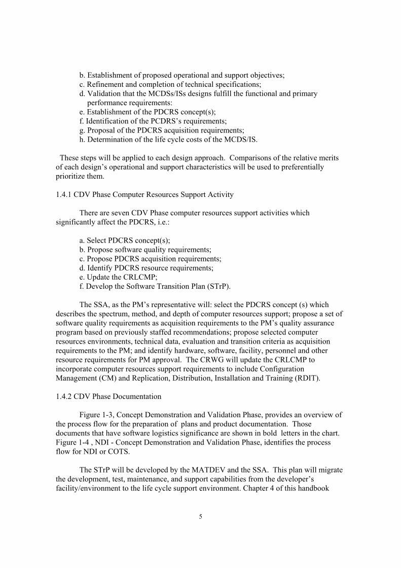
b. Establishment of proposed operational and support objectives; c. Refinement and completion of technical specifications; d. Validation that the MCDSs/ISs designs fulfill the functional and primary performance requirements: e. Establishment of the PDCRS concept(s); f. Identification of the PCDRS’s requirements; g. Proposal of the PDCRS acquisition requirements; h. Determination of the life cycle costs of the MCDS/IS. These steps will be applied to each design approach. Comparisons of the relative merits of each design’s operational and support characteristics will be used to preferentially prioritize them. 1.4.1 CDV Phase Computer Resources Support Activity There are seven CDV Phase computer resources support activities which significantly affect the PDCRS, i.e.: a. Select PDCRS concept(s); b. Propose software quality requirements; c. Propose PDCRS acquisition requirements; d. Identify PDCRS resource requirements; e. Update the CRLCMP; f. Develop the Software Transition Plan (STrP). The SSA, as the PM’s representative will: select the PDCRS concept (s) which describes the spectrum, method, and depth of computer resources support; propose a set of software quality requirements as acquisition requirements to the PM’s quality assurance program based on previously staffed recommendations; propose selected computer resources environments, technical data, evaluation and transition criteria as acquisition requirements to the PM; and identify hardware, software, facility, personnel and other resource requirements for PM approval. The CRWG will update the CRLCMP to incorporate computer resources support requirements to include Configuration Management (CM) and Replication, Distribution, Installation and Training (RDIT). 1.4.2 CDV Phase Documentation Figure 1-3, Concept Demonstration and Validation Phase, provides an overview of the process flow for the preparation of plans and product documentation. Those documents that have software logistics significance are shown in bold letters in the chart. Figure 1-4 , NDI - Concept Demonstration and Validation Phase, identifies the process flow for NDI or COTS. The STrP will be developed by the MATDEV and the SSA. This plan will migrate the development, test, maintenance, and support capabilities from the developer’s facility/environment to the life cycle support environment. Chapter 4 of this handbook

6
describes the outline of the STrP. The CRWG will update the CRLCMP and make changes if required to the Computer Resources Support Section of the ILSP prior to the next milestone. 1.5 ENGINEERING AND MANUFACTURING PHASE The Engineering and Manufacturing (EMD) Phase is used for MCDS/IS full scale development and primary systems integration (including ILS; Reliability, Availability, and Maintainability (RAM); and MANPRINT). Developmental and unit operational testing will be conducted and analyzed for assurance of technical, functional, and operational satisfaction of the requirements stipulated in the MNS, ORD, and the Information Requirements Specification (IRS). Other objectives of this phase are the preparations for production, production testing and deployment. The PM is responsible for the planning evaluation and implementation of full scale development, operational testing, and deployment. The PM will also identify the resources necessary to sustain the software logistics support after transition to include the resources necessary to maintain, replicate, distribute, download, install, and “delta-train” the MCDS/IS. 1.5.1 EMD Phase Computer Resources Support Activities The EMD Phase has six major computer resources support activities which affect PDCRS: a. Computer resources supportability assurance; b. Computer resources quality evaluation; c. Computer resources documentation and technical data certification; d. CRLCMP and Computer Resources Integrated Support Document (CRISD); e. Completion of STrP; f. Initiate development of the MCDS Software Fielding Plan(s) as an appendix of the CRLCMP. The Computer Resources Quality/Evaluation Plan will also be concerned with computer resources supportability requirements to include support system friendliness. The SSA will assure the PM that the contractually deliverable computer resources for use by the Life Cycle Computer Resources Support Environment (LCCRSE) has been evaluated using the Developmental Computer Resources Support Environment (DCRSE). The Computer Resources Quality Evaluation Plan or an approved software quality evaluation method will be used to evaluate the computer resources quality requirements. The SSA will contribute to the PM’s certification of documents and technical data which pertain to computer resources support issues and concerns. The documentation will be reviewed to assure that computer resources support requirements have been completely and satisfactorily addressed. The STrP will be completed and reviewed by representatives (e.g., management, technical, and administrative) from the PM, contractors and the Readiness Command. 1.5.2 EMD Phase Documentation

7
Figure 1-5, Engineering and Manufacturing Phase, provides an overview of the process flow for the preparation of plans and product documentation. Those documents that have software logistics significance are shown in bold letters in the chart. Figure 1-6, NDI - Engineering and Manufacturing Phase, identifies the process flow for NDI or COTS. During this phase the Software Fielding Plan is initiated. The Software Fielding Plan describes the requirements, constraints, issues, process activities, computer resources staffing and facilities used to insure orderly and timely fielding of BAS operational mission software/firmware after initial fielding and transition. Chapter 6 describes the plan and identifies potential input for the plan. The STrP is completed reviewed and coordinated. The ILSP and the CRLCMP are updated for the pending Milestone Review. 1.6 PRODUCTION AND DEPLOYMENT PHASE The Production and Deployment (PD) Phase is the acquisition period used for the preparation ,support and execution for the production and deployment of the MCDS/IS. During this phase operational units are trained; computer resources and computer resources support hardware and software/firmware are procured; software logistic support is provided; production testing and evaluation, to include software, is accomplished; and any pre-planned product improvements are applied. 1.6.1 PD Phase Computer Resources Support Activities The PD Phase is accompanied by six computer resources activities which significantly affect PDCRS, specifically; a. Implement the STrP; b. Acquire and install of the LCCRSE and Life Cycle Computer Resources Support Test Environment (LCCRSTE); c. Acquire other post deployment computer resources; d.Staff and train personnel; e. Demonstrate PDCRS capability; f. Complete the Software Fielding Plan. The PD Phase will include the staffing and training of personnel to provide PDCRS; the transfer of resource assets from the DCRSE to the LCCRSE (i.e., host computer system, target computer system or “mock-up”, firmware support systems, integrated testing system, automated documentation, configuration management systems and tracking systems). There will be a demonstration of the capability of the LCCRSE to adequately support the MCDS/IS throughout the remainder of its operational life. 1.6.2 PD Phase Documentation Figure 1-7, Production and Deployment Phase, provides an overview of the process flow for the preparation of plans and product documentation. Those documents that have

8
software logistics significance are shown in bold letters in the chart. Figure 1-8, NDI - Production and Deployment Phase, identifies the process flow for NDI or COTS. During this phase the Materiel Fielding Plan (MFP) is prepared. The MFP serves as the single, stand-alone document which contains plans, schedules, procedures, and materiel fielder and gaining MACOM actions necessary to successfully ship, deprocess, deploy and sustain materiel being fielded for the first time within a gaining MACOM. Chapter 5 identifies the two sections of the MFP with significant software logistics input. 1.7 OPERATIONS AND SUPPORT PHASE The Operations and Support (OS) Phase begins upon completion of management responsibility transfer from the MCDS/IS PM to the Readiness Command. During this phase, the system is deployed and operated in the field; the system’s effectiveness and benefits are evaluated; and the MATDEV/PM implements short term or long term improvements. The fielded system will be evaluated to ensure that required computer resources and computer resources support resources capabilities are successfully provided; the identified mission is accomplished; and that any deficiencies requiring correction are identified. The SSA will coordinate with the Readiness Command (RC) system manager/item manager to provide post fielding support reviews in order to: a. Identify and resolve any new computer resources supportability issues and problems; b. Determine the validity of the current computer resources support concept, initial engineering estimates for spares and operational media, and the maintenance and resupply process; c. Determine the adequacy and integration of the computer resources support environment. 1.7.1 OS Phase Computer Resources Support Activities The OS Phase is supported by six primary PDCRS activities: a. Continued PDCRS management; b. Performance of PDCRS operations; c. Provision of computer resources products; d. Maintenance of the CRLCMP/CRISD; e. Evaluation and maintenance of computer resources (support) quality; f. Computer resources configuration management. The management of PDCRS operations are the responsibility of the assigned RC Software Engineering Directorate (especially the SSA). After transition the RC is responsible for configuration management of the software package. The RC provides supply support (field and depot) through the National Inventory Control Point (NICP). The RC’s Logistic and Maintenance Directorate (LMD) identify MCDS field problems through various reporting documents (e.g., Equipment Improvement Report

9
[EIR] and the Quality Deficiency Report [QDR]). Logistics Area Representatives (LAR) provide on-site training and assist the user personnel in preparing problem reports. The RC may also identify a “hotline” telephone number in the MFP to expedite problem reporting. 1.7.2 Problem Resolution The designated SED/SSA problem solution must be approved by the Configuration Control Board (CCB) and can be fielded only after a Software Materiel Release, in accordance with AR 700-142. Once approved for release, the system manager will coordinate the fielding of the software/firmware version release. The SSA will: a. Replicate the new software/firmware version onto deliverable media; b. Prepare a new version release package comprised of replicated load media, documentation changes, instructions and material exchange acknowledgment forms; c. Distribute the new version package; d. Provide installation/downloading teams, if required; e. Provide installation assistance, if required; f. Provide “delta-training” when required; g. Resupply user units with media to replace worn, damaged, or obsolete media. 1.7.3 OS Phase Documentation Figure 1-, Operations and Support Phase, provides an overview of the process flow for the preparation of plans and product documentation. Those documents that have software logistics significance are shown in bold letters in the chart. Figure 1-10, NDI - Operations and Support Phase, identifies the process flow for NDI or COTS. New software version releases may require a SFP. Pre-planned Product Improvements will usually require a MFP.

10
ASCFPCIPCRLCMPDTCEAEISIACOPICTPIEPILSPMANPRINTMARBMEPORDPRMPRAMSDPSMMPSSSTDPTEMPTIWGTR/TEATSP
Acquisition StrategyConcept Formulation PackageCritical Intelligence ParameterComputer Resources Life-Cycle Management PlanDesign-to-CostEnvironmental AssessmentEnvironmental Impact StatementInternational Armaments Cooperative Opportunities PlanIndividual and Collective Training PlanIndependent Evaluation PlanIntegrated Logistic Support PlanManpower and Personnel IntegrationMateriel Acquisition Review BoardMaster Evaluation PlanOperational Requirements DocumentProduction Readiness Master PlanReliability, Availability, MaintainabilitySystem Development PackageSystem MANPRINT Management PlanSpecial Study GroupTest Design PlanTest and Evaluation Master PlanTest Integration Working GroupTransportability Report/Transportability Engineering AnalysisThreat Support Package
DEFINITIONSCONCEPT EXPLORATION AND DEFINITION PHASE

11
Figure 1-1 Concept Exploration and Definition Phase
ICTP
MANPRINTTIWG EX/EIS ILSP
INITIALSMMP
TSP
IACOP TR/TEA
CRLCMP CIPs
RAMRATIONALE AS
CFP
PRMP
ORD
ESTABLISHTIWG
SSS DTC UPDATEAS
MARB
IEP/MEP
TEMP
TDP
SDP
Figure 1-1

12
DEFINITIONSNDI - CONCEPT EXPLORATION AND DEFINITION PHASE
ASCIPCRLCMPDTCEAEISIACOPICTPIEPILSPMANPRINTMARBORDRAMSDPSMMPSSSTDPTEMPTIWGTR/TEATSP
Acquisition StrategyCritical Intelligence PerimeterComputer Resources Life-Cycle Management PlanDesign-to-CostEnvironmental AssessmentEnvironmental Impact StatementInternational Armaments Cooperative Opportunities PlanIndividual and Collective Training PlanIndependent Evaluation PlanIntegrated Logistic Support PlanManpower and Personnel IntegrationMateriel Acquisition Review BoardOperational Requirements DocumentReliability, Availability, Maintainabilitysystem Development PackageSystem MANPRINT Management PlanSpecial Study GroupTest Design PlanTest and Evaluation Master PlanTest Integration Working GroupTransportability Report/Transportability Engineering AnalysisThreat Support Package

13
Figure 1 - 2 NDI - Concept Exploration and Definition Phase
ICTP
MANPRINTTIWG EA/EIS ILSP
INITIALSMMP
TSP
IACOP TR/TEA
CRLCMP CIPs
RAMRATIONALE
ASORD
FORMTIWG
SSS DTC MARB
IEP
TEMP
TDP
SDP

14
DEFINITIONSCONCEPT DEMONSTRATION-VALIDATION PHASE
APASASARCBCEBOIPCFPCOEACRLCMPDABDCPDTEAEISHHAHHARIEPILSPIPRIPSMARBMEPORDOTPPEPPRMPQQPRIRFPSARSRSSSEPTDPTMDETEMP
Acquisition PlanAcquisition StrategyArmy Systems Acquisition Review CouncilBaseline Cost EstimateBasis of Issue PlanConcept Formulation PackageCost and Operational Effectiveness AnalysisComputer Resources Life-Cycle Management PlanDefense Acquisiton BoardDecision Coordination PaperDevelopment TestEnvironmental AssessmentEnvironmental Impact StatementHealth Hazard AssessmentHealth Hazard Assessment ReportIndependent Evaluation PlanIntegrated Logistic Support PlanIn-Process ReviewIntegrated Program Summarymateriel Acquisition REview BoardMaster Evaluation PlanOperation Requirements DocumentOutline Test PlanProducibility Engineering and PlanningProduction Readiness Master PlanQualitative and Quantitative Personnel Requirements InformationRequest for ProposalSafety Assessment ReportSoftware Requirements SpecificationSource Selection Evaluation PlanTest Design PlanTest, Measurement and Diagnostic EquipmentTest and Evaluation Master Plan

15
Figure 1 - 3 Concept Demonstration and Validation Phase
ILSPUPDATE
SSEP EA/EIS BCE
CRLCMPUPDATE
CFP
ORD
COEA
ORD AS
PRMP
MARB
TRANSITIONPLAN
PEP
BOIP/QQPRI TMDE
OTP DT HHA/HHAR/SAR TESTING
DABASARC
IPR
SRS IPS
UPDATETEMP
MEP TDP IEP
Figure 1-3
16
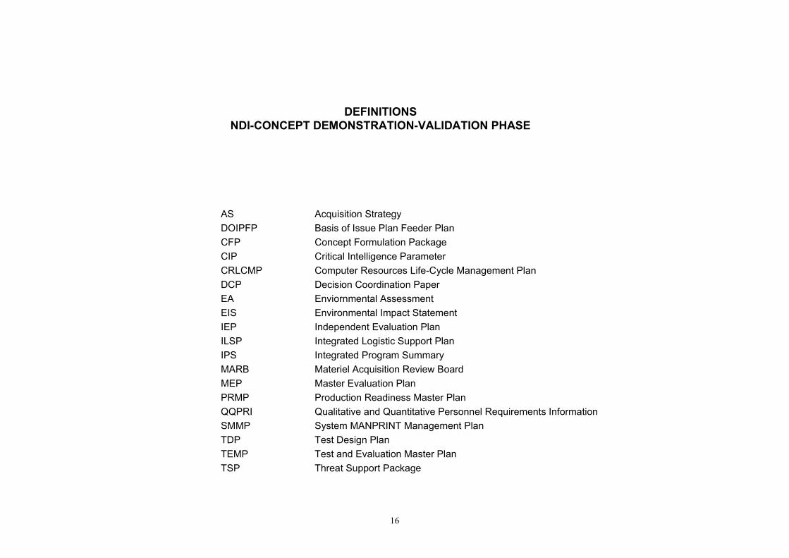
DEFINITIONSNDI-CONCEPT DEMONSTRATION-VALIDATION PHASE
ASDOIPFPCFPCIPCRLCMPDCPEAEISIEPILSPIPSMARBMEPPRMPQQPRISMMPTDPTEMPTSP
Acquisition StrategyBasis of Issue Plan Feeder PlanConcept Formulation PackageCritical Intelligence ParameterComputer Resources Life-Cycle Management PlanDecision Coordination PaperEnviornmental AssessmentEnvironmental Impact StatementIndependent Evaluation PlanIntegrated Logistic Support PlanIntegrated Program SummaryMateriel Acquisition Review BoardMaster Evaluation PlanProduction Readiness Master PlanQualitative and Quantitative Personnel Requirements InformationSystem MANPRINT Management PlanTest Design PlanTest and Evaluation Master PlanThreat Support Package

17
Figure 1 - 4 NDI Concept Demonstration and Validation Phase
UPDATEEA/EIS
UPDATEILSP
UPDATECRLCMP
UPDATESMMP
TSP
CIPs
BOIPFD/QQPRI
AS
CFP
PRMP IEP/MEP
TEMP
TDP
MARB
DCP
IPS

18
DEFINITIONSENGINEERING AND MANUFACTURING DEVELOPMENT PHASE
APASASARCBOIPFDCOEACRLCMPDABDTHHAHHARIEPILSMTILSPIPRLSARMARBMEPMFPMSPNETPOTPPEPPRMPQQPRIRFPSARSFPTCTDPTEMP
Acquisition PlanAcquisition StrategyArmy Systems Acquisition Review CouncilBasis of Issue Plan Feeder DataCost and Operational Effectiveness AnalysisComputer Resources Life-Cycle Management PlanDefense Acquisition BoardDevelopment TestHealth hazard AssessmentHealth hazard Assessment ReportIndependent Evaluation PlanIntegrated Logistic Support Management TeamIntegrated Logistic Support PlanIn-Process ReviewLogistic Support Analysis ReportMateriel Acquisition Review BoardMaster Evaluation PlanMateriel Fielding PlanMission Support PlanNew Equipment Training PlanOutline Test PlanProducibility Engineering and PlanningProduction Readiness Master PlanQualitative and Quantitative Personnel Requirements InformationRequest for ProposalSafety Assessment ReportSoftware Fielding PlanType ClassificationTest Design PlanTest and Evaluation Master Plan

19
ESTABLISHILSMT
ILSPUPDATE
SFP
CRLCMPUPDATE
MFPBOIPFD/QQPRI
MSP
PEP
RFP
AP
OTP
TECHNICALMANUALS
UPDATECOEA
DT HHA/HHAR/SAR
UPDATEPRMP
UPDATEAS
SOFTWAREDEVELOPMENTSPECIFICATION
LSAR
NETP FACILITIZATION TC
MARBDAB
ASARCIPR
UPDATETEMP
MEP TDP IEP
Figure 1-5 Engineering and Manufacturing Development Phase
TESTING

20
DEFINITIONSNDI-ENGINEERING AND MANUFACTURING DEFVELOPMENT PHASE
APASASARCDOIPFDCOEACRLCMPDTHHAHHARIEPILSPIPRMARBMEPMFPMSPNETPOTPPEPPRMPQQPRIRFPSARSDDSDPSFPSSSTCTDPTEMP
Acqusition PlanAcquisition StrategyArmy Systems Acquisition Review CouncilBasis of Issue Plan Feeder DataCost and Operational Effectivenss AnalysisComputer Resources Life-Cycle Management PlanDevelopment TestHealth Hazard AssessmentHealth Hazard Assessment ReportIndependent Evaluation PlanIntegrated Logistic Support PlanIn-Process ReviewMateriel Acquisition Review BoardMaster Evaluation PlanMateriel Fielding PlanMission Support PlanNew Equipment Training PlanOutline Test PlanProducibility Engineering and PlanningProduction Readiness Master PlanQualitative and Quantitative Personnel Requirements InformationRequest for ProposalSafety Assessment ReportSoftware Design DescriptionSystem Development PackageSoftware Fielding PlanSpecial Study GroupType ClassificationTest Design PlanTest and Evaluation Master Plan

21
ILSPUPDATE
SFP
CRLCMPUPDATE
MFPBOIPFD/QQPRI
MSP
PEP
RFP
AP
OTP
TECHNICALMANUALS
UPDATECOEA
DT HHA/HHAR/SAR
NETP FACILITIZATION TC
MARBDAB
ASARCIPR
UPDATETEMP
MEP/IEP TDP
Figure 1-6 NDI Engineering & Manufacturing Development Phase Category B
TESTING
SSS SDD
UPDATEAS
UPDATEPRMP
SDP DTC
22
DEFINITIONSPRODUCTION AND DEPLOYMENT PHASE
APBOIPCOEACRLCMPILSPLSARMFPMSPNETPOTPQQPRIRFPSFPSSEPTDP
Acquisition PlanBasis of Issue PlanCost and Operational Effectiveness AnalysisComputer Resources Life-Cycle Management PlanIntegrated Logistic Support PlanLogistic Support Analysis ReportMateriel Fielding PlanMission Support PlanNew Equipment Training PlanOutline Test PlanQualitative and Quantitative Personnel Requirements InformationRequest for ProposalSoftware Fielding PlanSource Selection Evaluaiton PlanTest Design Plan

23
Figure 1 - 7 Production and Deployment Phase
TDPPRODUCTION OTP
FIELDSUPPORT
SOFTWAREPRODUCTION
SPECIFICATION
UPDATECOEA
TECHNICALMANUALS
SSEP
RFP
AP
ILSPUPDATE
SFPUPDATE
CRLCMPUPDATE
MFP
MSP
LSAR NETP BOIP/QQPRI

24
DEFINITIONSPRODUCTION AND DEPLOYMENT PHASE
APBOIPCOEACRLCMPILSPLSARMFPMSPNETPOTPQQPRIRFPSFPSSEPTDP
Acquisition PlanBasis of Issue PlanCost and Operational Effectiveness AnalysisComputer Resources Life-Cycle Management PlanIntegrated Logistic Support PlanLogistic Support Analysis ReportMateriel Fielding PlanMission Support PlanNew Equipment Training PlanOutline Test PlanQualitative and Quantitative Personnel Requirements InformationRequest for ProposalSoftware Fielding PlanSource Selection Evaluaiton PlanTest Design Plan

25
Figure 1 - 8 NDI Production and Deployment Phase
TDPPRODUCTION OTP
FIELDSUPPORT
SOFTWAREPRODUCTION
SPECIFICATION
UPDATECOEATECHNICAL
MANUALS
SSEP
RFP
AP
ILSPUPDATE
SFPUPDATE
CRLCMPUPDATE
MFP
MSP
LSAR NETP BOIP/QQPRI
SOFTWARETRANSITION
PLAN

26
DEFINITIONSOPERATIONS AND SUPPORT PHASE
BASMFPOTPRDITSFPSOPTDP
Battlefield Automated SystemMateriel Fielding PlanOutline Test PlanReplication, Distribution, Installation and TrainingSoftware Fielding PlanStanding Operating ProcedureTest Design Plan

27
Figure 1 - 9 Operations and Support Phase
TDPPRODUCTION OTP
SOFTWAREPROBLEM/CHANGEREPORT
SOFTWAREMAINTENANCE
PROCESS
SOFTWAREPRODUCTION
SPECIFICATION
TECHNICALMANUALS
NEWVERSION
SFP
MFP
REPLICATION DOWNLOADINGINSTALLATION
CONFIGURATIONTRACKING
DISTRIBUTION TRAINING
RDIT SOP BAS APPENDIX
FIELDSUPPORT

28
DEFINITIONSOPERATIONS AND SUPPORT PHASE
BASMFPOTPRDITSFPSOPTDP
Battlefield Automated SystemMateriel Fielding PlanOutline Test PlanReplication, Distribution, Installation and TrainingSoftware Fielding PlanStanding Operating ProcedureTest Design Plan

29
Figure 1 - 10 NDI Operations and Support Phase
TDPPRODUCTION OTP
SOFTWAREPROBLEM/CHANGEREPORT
SOFTWAREMAINTENANCE
PROCESS
SOFTWAREPRODUCT
SPECIFICATION
TECHNICALMANUALS
NEWVERSION
SFP
MFP
REPLICATION DOWNLOADINGINSTALLATION
CONFIGURATIONTRACKING
DISTRIBUTION TRAINING
RDIT SOP BAS APPENDIX
FIELDSUPPORT

30
Left Blank

31
CHAPTER 2 MODEL COMPUTER RESOURCES SUPPORT SECTION
OF THE INTEGRATED LOGISTIC SUPPORT PLAN
2.0 GENERAL 2.01 Integrated Logistic Support Plan The Integrated Logistic Support Plan (ILSP) is a government prepared document which presents the total Integrated Logistic Support (ILS) strategy for a materiel system. The ILSP describes the overall ILS program and includes all ILS program requirements, tasks, and milestones for the current acquisition phase. The ILSP identifies specific tasks to be accomplished, the responsible activity, and the schedule for task completion. An ILSP projects ILS planning for the succeeding acquisition phases. During any phase, the subsequent phase will receive the greatest attention in the projection effort. Guidance for the preparation of the ILSP can be found in DA PAM 700-55, Instructions for Preparing the Integrated Logistic Support Plan. 2.0.2 Computer Resources Support Section of the ILSP The Computer Resources Support (CRS) section of the ILSP describes ILS requirements, constraints, issues , management and development procedures unique to stand-alone or embedded computer hardware and software support. The major portions of the CRS section of the ILSP include: ILSP Paragraph Number ILSP Paragraph Title 2.6.8 Computer Resources Support 2.6.8.1 Scope and Computer Resources 2.6.8.2 Computer Resources Acquisition Methodology 2.6.8.3 Computer Resources Support Concept 2.6.8.4 Computer Resources Support Strategy 2.6.8.5 Computer Resources Support Policies, Procedures, and Practices 2.6.8.6 Computer Resources Support Program 2.6.8.7 Organizations with Integrated Logistic Support Responsibilities for Computer Resources Support 2.6.8.8 Computer Resources Integrated Logistic Support Requirements 2.6.8.9 Software Documentation 2.6.8.10 Software Support Environments

32
2.0.3 The Computer Resources Life-Cycle Management Plan The Computer Resources Life-Cycle Management Plan(CRLCMP) is included as an annex to the ILSP. The CRLCMP is a comprehensive management plan for software development, test, support and performance of related tasks over the course of the BAS’s life cycle. An approved and updated CRLCMP is required prior to each Milestone Review 2.1. COMPUTER RESOURCES SUPPORT (2.6.8) CRS is the resources management and the activities required to develop, maintain, and provide Replication, Distribution, Installation and Training (RDIT) support for the Battlefield Automated System’s (BAS) Computer Software Configuration Items (CSCI). CRS defines and employs the facilities, hardware, software, documentation and personnel needed to operate and support BASs. Maintenance of CSCIs include the adaptation, correction and improvement of BAS software functional and performance capabilities. CRS activities take place in either pre-deployment, transitional or post-deployment support environments. CRS allocations are distributed between developmental, test, operational, automatic test equipment, and Post-Deployment Software Support (PDSS). Pre -deployment CRS applies to BAS design, development and test & evaluation activities. After pre-deployment the operational software and CRS are transferred to the field and PDSS site, respectively. Master and “working” copies of allocated, functional and product base lines of operational software versions will be available at the Life-Cycle Software Engineering Center (LCSEC). Support includes the establishment, implementation and enforcement of appropriate software standards, practices and techniques. 2.1.1 Scope (2.6.8.1) This section addresses the approach for the design, development, test/evaluation, installation, and application of the subject BAS’s computer resources. This paragraph should identify and concisely describe: the organizations responsible for CRS; the personnel categories; the facilities for the performance of CRS; and the CRS development and post-development environments and tools. This section will identify the actions required to develop and support the modification (i.e., adaptation, correction or perfection) of CSCIs and the RDIT capability. 2.1.1.1 Computer Resources Computer Resources are all of the computer equipment including replicators, programs, data, and associated documentation, contractual services, personnel, and supplies including Computer Programming Media (CPM) associated with BAS’s program management, and the BAS’s design/development, test & evaluation, transition, fielding, and PDSS. Briefly describe the BAS’s computer resources. The descriptions will mature as the resources’ identity are revealed and their integrated developments proceed. Henceforth, the rather broad term “software” includes all computer modifiable instructions, data, graphics, information and documentation resident on eraseable and reprogrammable

33
CPM [i.e., Random Access Memory (RAM), Winchester hard disk, Eraseable-Programmable Read-Only Memory (EPROM) chips, and multi-track reel or cartridge tape]. 2.1.2 Computer Resources Acquisition Methodology (2.6.8.2) Briefly describe the acquisition methodology , as it applies to CRS, (i.e., the acquisition, organization, management and proposed support method). Refer to the BAS Acquisition Strategy, the Acquisition Plan and the Army Acquisition Process depicted in Figure 2-1. This methodology should include the allocation of management and product/ service support responsibilities to the government or commercial support contractors. DA PAM 700-127, Integrated Logistic Support Manager’s Guide, references the Non-Developmental Items (NDI) Acquisition method as the preferred US Army Acquisition Strategy. Consideration of NDI hardware, firmware and software requires significantly different logistic approaches from standard “MIL-SPEC” hardware/firmware and DOD-STD 498 Software Developments. 2.1.3 Computer Resources Support Concept (2.6.8.3) The Computer Resources Support Concept (CRSC) is an organized application of the BAS Programs computer resources (i.e., funds, management, facilities, equipment, software systems, personnel, schedule, etc.) to provide the support for the acquisition, modification and RDIT of the BAS’s software system. The concept evolves through the three acquisition stages. During the pre-deployment stage, the concept revolves about the software supportability of the developing system, by the Software Engineering Directorate (SED) and planning for PDSS. During the transition stage, the concept establishes the transference of the BAS software (systems, support and applications) and the developing contractor’s Software Development and Maintenance Facilities to the BAS’s LCSEC. The PDSS stage concept concentrates on ensuring continual supportability, and PDSS management and operations. The CRSC is based on the application of a host computer system, with accompanying software support systems to develop and support the operational and support software of the BAS. The host computer provides the automated storage environment for BAS software in a source (i.e. man readable/modifiable) form and a form compiled for the target computer system. The host environment uses software management and software engineering methodologies through the application of software management, administration and engineering tools. The tools will support software design, development, quality assurance/control, test & evaluation, support, maintenance, modification, configuration management and resource management.

34
PHASE 0CONCEPT
EXPLORATION
SYS RQMTSDEFINITION
PHASE 1DEMON-
STRATIONVALIDATION
PHASE IIENGINEERING & MANUFACTURING
(I.E. DEVELOPMENT)
PHASE IIIPRODUCTIONDEPLOYMENT
SYS/SOFTWARERQMTS
DEFINITION***
PHASE IVOPERATIONS
ANDSUPPORT
REPLICATION,MATERIELFIELDING,TRAINING
FIELDEDSYSTEMS
OPERATIONS& PDSS
SOFTWAREDEVELOP-
MENT
SYSTEMINTEGRA-TION ANDTESTING
OT&E
PHASE
ACTIVITY
SOFTWAREANALYSIS PRELIMINARY
DESIGN DETAILEDDESIGN CODE/UNIT
TESTING COMPONENTINT/TESTING END ITEM
TESTING
PRODUCTBASELINE(S)
SYSTEMDESIGNREVIEW
SOFTWARESPECIFICATION
REVIEW
PRELIMINARYDESIGNREVIEW
CRITICALDESIGNREVIEW
TESTREADII-NESS
REVIEW
FUNCTIONALCONFIGAUDIT
PHYSICALCONFIGAUDIT
ALLOCATEDBASELINE(S)FUNCTIONAL
BASELINE
SOFTWAREDEVELOPMENTCYCLEACTIVITY
SOFTWAREREVIEWS& AUDITS
MILESTONE IORD
MILESTONEII
MILESTONEIII
MILESTONEIV
Figure 2 - 1 US Army Acquisition Process *** e.g., CPM & Reprogramming Equipment)
35
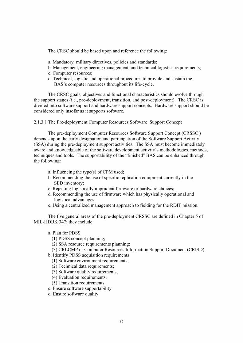
The CRSC should be based upon and reference the following: a. Mandatory military directives, policies and standards; b. Management, engineering management, and technical logistics requirements; c. Computer resources; d. Technical, logistic and operational procedures to provide and sustain the BAS’s computer resources throughout its life-cycle. The CRSC goals, objectives and functional characteristics should evolve through the support stages (i.e., pre-deployment, transition, and post-deployment). The CRSC is divided into software support and hardware support concepts. Hardware support should be considered only insofar as it supports software. 2.1.3.1 The Pre-deployment Computer Resources Software Support Concept The pre-deployment Computer Resources Software Support Concept (CRSSC ) depends upon the early designation and participation of the Software Support Activity (SSA) during the pre-deployment support activities. The SSA must become immediately aware and knowledgeable of the software development activity’s methodologies, methods, techniques and tools. The supportability of the “finished” BAS can be enhanced through the following: a. Influencing the type(s) of CPM used; b. Recommending the use of specific replication equipment currently in the SED inventory; c. Rejecting logistically imprudent firmware or hardware choices; d. Recommending the use of firmware which has physically operational and logistical advantages; e. Using a centralized management approach to fielding for the RDIT mission. The five general areas of the pre-deployment CRSSC are defined in Chapter 5 of MIL-HDBK 347; they include: a. Plan for PDSS (1) PDSS concept planning; (2) SSA resource requirements planning; (3) CRLCMP or Computer Resources Information Support Document (CRISD). b. Identify PDSS acquisition requirements (1) Software environment requirements; (2) Technical data requirements; (3) Software quality requirements; (4) Evaluation requirements; (5) Transition requirements. c. Ensure software supportability d. Ensure software quality

36
e. Develop and implement the Software Transition Plan (STrP) (1) Software development transition; (2) SSA transition. 2.1.3.2 Transitional Computer Resources Software Support Software transition is composed of software development transition and SSA transition. The objective of software development transition is for the Government to acquire the resources, data and knowledge necessary to competently implement the approved PDSS concept. The transitional concept usually entails transition planning and the subsequent transfer of the development contractor’s finished BAS software product as well as the operational software development and maintenance environments to the SED/ SSA responsible for BAS PDSS. Furthermore this concept may include combinations of the following requirements: a. Equipment and software system acquisition and installation; b. Government personnel software support training for the subject BAS; c. Limited contractor software support services, while the Government personnel achieve required expertise; d. Preparation of configuration status accounting reports; e. Test which prove unequivocally that the transferred development and maintenance environments are completely functional and operable, and that the SED personnel trained to operate them can support the BAS; f. The proper recording and disposition of unnecessary contractor computer resources (hardware, prototypes, firmware, etc.) to the proper Army Depot. SSA transition is composed of the activities required to implement the PDSS concept at the emplaced LCSSE. The focus of the SSA transition is PDSS operations. Important SSA activities include: a. Staffing and training; b. Turnover, installation, checkout, and integration of any hardware or software received from sources other than the developing agency; c. Implementation of all required PDSS activities and capabilities (e.g., problem identification and fault isolation, corrective action, software generation, integration and test, replication support systems, and document production); d. Approval and implementation of applicable software management plans; e. Verification that transition milestones have been correctly completed and that all necessary resources are available; f. Integration of all PDSS activities into a cohesive PDSS process; g. Reporting software transfer; h. Determination that security requirements have been satisfied. References for the software transition are provided in Section 5.3.5 of MIL-HDBK-347. Appendix E of MIL-HDBK-347 provides a software transition list. DI-E-7142 describes the activities and events necessary to transfer software support for contractually

37
deliverable software from a contractors Developmental Software Support Environment (DSSE) to the contracting activity’s designated LCSSE. 2.1.3.3 Post Deployment Software Support Concept PDSS is that part of CRS required to sustain, adapt, correct or perfect a deployed system’s computer software, as defined by the user or the Center’s/School’s software representative. PDSS is a process which periodically distributes new versions of fielded software to obtain, maintain, retain or enhance BAS effectiveness. A new software “version” is a set of software and/or firmware changes in response to changes in requirements or concepts. Basically the problems are reviewed by pertinent parties, solved, and tested by SED/SSA (if deemed a software problem), approved/disapproved by the (Software) Configuration Control Board, and distributed to the field. The software versions incorporate changes required to do the following: a. Maintain system performance in response to changing threats, doctrine, tactics, and interoperability requirements; b. Correct latent errors; c. Provide software developed as part of materiel changes representing adaptations of the system performance envelope. 2.1.4 Computer Resources Support Strategy (2.6.8.4) The Computer Resources Support Strategy (CRSS) is a coordinated process of support planning of program characteristics, products and services, personnel and support environments. The strategy’s goal is to plan for the following: a. Computer resources support evaluation; b. Managerial and technical responsibilities for CRS; c. CRS activities coordination and execution; d. The performance requirements for each CRS activity. Each acquisition stage includes specific CRS activities. These activities are shown in Figure 2-2. 2.1.4.1 CRSS - Concept Exploration/Definition Phase The Concept Exploration/Definition (CED) Phase includes four major CRS activities: a. Designate the SSA; b. Investigate alternative PDSS concepts;

38
Figure 2-2 Phased Acquisition Process/II S/Software Support
SYSTEMACQUISITIONPROCESS
ACTIVITIESFORINTEGRATEDLOGISTICSUPPORT
EVOLUATIONSOFTWARESUPPORT
ACTIVITIESFORSOFTWARESUPPORT
Pre-Deployment (SW) Support Stage(Initial Software Development)
ConceptExploration/Definition
Define theSupport• Develop ILS strategy• Designate the SSA• Investigate alternate support concepts• Influence product definition
ConceptDemonstration/
Validation
Design forSupport• Identify/Design/ assess logistics implications of each major system alternative• Influence selection of major system alternative
Engineering&
Manufacturing
Design theSupport• Complete Design of the logistics support system• Ensure ILS is part of design tradeoffs• Test & evaluate support system• Design support items
Production&
Deployment
Acquire theSupport• Acquire all necessary support items
OperationsSupport
Provide theSupport• Provide system logistic support
• Develop PDSS strategy
• Investigate alternate PDSS concepts
• Select PDSS concept• Propose SW quality requirements• Propose PDSS acquisition requirements• Identify SSA resource requirement• Develop CRMP• Develop Transition Plan
• Ensure SW supportability• Evaluate SW quality• Certify SW documents & technical data• Maintain CRMP• Maintain & Update the Transition Plan
• Implement transition plan• Acquire & Install SEE/STE• Acquire SSA resource requirements• Staff/train personnel• Demo PDSS capability
• Manage PDSS• Conduct PDSS operations• Provide SW Product Logistics Support• Maintain CRMP• Evaluate & maintain SW quality• SW Configuration Management
PDSS Stage(Follow-on SWDevelopment)

39
c. Develop the PDSS strategy; d. Influence the BAS product definition. The Program Manager (PM) will designate and charter the SSA. The SSA supports the PM’s acquisition, transition and the post-deployment system manager. The SSA’s pre-development support will include planning, identifying requirements (e.g., funding, hardware and software, facility, equipment, technical data, data management and logistic) software quality, support and transition. During the post-deployment stage, the SSA will be concerned with PDSS operations and software quality management. A charter will be generated to define the SSA’s authority, responsibilities, to identify taskings and establish organizational management, support and technical relationships. The software support manager will collaborate with appropriate managers and technical managers, engineers and specialists (i.e., design/development, test, logistics, PDSS engineers and training specialists) to develop the PDSS strategy. This panel of experts will determine and investigate alternative PDSS concepts. The software support manager will influence the BAS product definition with the information generated form the knowledge, experiences and analysis of the panel of experts. 2.1.4.2 CRSS - Concept Demonstration/Validation Phase The Concept Demonstration/Validation (CDV) Phase involves seven primary CRS activities: a. Select a PDSS concept; b. Propose software quality requirements; c. Propose PDSS acquisition requirements; d. Identify SSA resource requirements; e. Develop and update the CRLCMP; f. Develop the STrP; g. Develop the Life Cycle Support Environment (LCSSE) and Life Cycle Software Support Test Environment (LCSSTE). Initially, the SSA will select the PDSS concept which describes the spectrum, method and depth of software support during the deployment. The PDSS concept will become an integral component of the ILS concept (Paragraph 2.6.8.3). The SSA will propose a comprehensive set of quality requirements to the Project Manager’s (PM) Quality Assurance Program. These candidate requirements will have been derived from those recommended by user, combat and materiel developers, SSA staff, and ancillary matrix organizations. The SSA will propose to the PM candidate software environments (i.e., Developmental Software Support Environment (DSSE), Developmental Software Support Test Environment (DSSTE), LCSSE, and LCSSTE), technical data, evaluation, and transition requirements as perspective acquisition requirements to the PM. Appropriate

40
consideration must be given to existing, available integrable and duly warranted Commercial Off-The-Shelf (COTS)/ NDI software tools for the development, test, and support environments (e.g., sets of software design/development, test, maintenance, support, configuration management, data management and program management software tool packages). The SSA will identify its own hardware, software, facility, personnel and other resource requirements, necessary to support the PM’s product/service cycle. (Reference Appendix C of MIL-HDBK 347). The Computer Resources Working Group (CRWG) will develop the CRLCMP. The SSA will ensure that the CRWG representative from SED identifies and promotes the requirements and concerns of the SED organization responsible for RDIT. Further, that the CRWG recognizes, implements, and supports RDIT requirements. The system contractor, materiel developer and SSA will develop the STrP. The transition of software is two fold; software development transition and SSA transition. Software development transition is the migration of the software development and development support capabilities to the SSA. SSA transition encompasses activities required for the SSA to implement the PDSS concept, once the PDSS environment is emplaced The development of the LCSSE and LCSSTE involves the consolidation of the developmental and support capabilities of contractor-driven DSSE against the Government available computer resources (e.g., equipment, software assets, expertise, and technical and administrative support). The Government determines which of its assets will replace relative equivalents from the DSSE without added expenditure. The determination of unnecessary DSSE assets eliminates “dead weight” costs. Untried asset acquisition will be discouraged, unless its utility to the LCSSE and SED can be unquestionably proven. The SSA will consider the LCSSE configuration, its component definitions/ descriptions, integration scheduling, funding, transportation (i.e., Software Support Transition Plan), shipping, storage, security, facility requirements (office space, secure work space, power, environmental control, signaling, communications, storage and security, engineering installation and implementation planning, and verification and validation). The SSA will determine what personnel expertise is necessary from the LCSS and available for allocation to the BAS’s PDSS. 2.1.4.3 CRSS - Engineering and Manufacturing Development Phase The Engineering and Manufacturing Development (EMD) Phase is supported by five major CRS activities: a. Software supportability assurance; b. Software quality evaluation; c. Software documentation and technical data certification;

41
d. CRLCMP/CRISD maintenance; e. Prepare LCSSE and LCSSTE plans. The tenets of software supportability assurance will be established in the Software Quality/Evaluation Plan(s) via contributions from the SSA. The requirements and stipulations will be derived from paragraph 5.3.3 of MIL-HDBK-347; DOD-STD-1467; DI-E-7140; DI-E-7142; and DI-E-7143. The SSA will consider the characteristics of the software product, the software environments, and the status of the SSA resources. Particular attention will be given to software contractor capability and capacity, support complexity, support system friendliness, technical effectiveness and efficiencies, DSSE and LCSEE compatibility, correctness, testability and flexibility, user suitability and operability. The SSA will ensure that the contractually deliverable software will be capable of being evaluated, generated, installed, integrated, tested and maintained using the contracting activity approved DSSE and designated LCSSE. The software support quality requirements, stipulated in the Software Quality Plan will be evaluated with a standard Software Quality Evaluation Plan or in situ with an approved software quality evaluation method including the following: a. Establishment of objective and subjective bases for software quality evaluation; b. Software quality data acquisition process; c. Application of software quality metrics or indicators algorithms; d. Qualitative and quantitative results interpretation; e. Software quality report(s). Data acquisition will include authenticating specifications, verifying requirements, and evaluating software quality plans, records and activities. The SSA will contribute to the PM’s certification of documents and technical data which pertain to software support subjects and issues. The documentation will be investigated to ensure that computer resource support requirements have been correctly and completely addressed. The SSA’s CRWG representative will provide computer resource support contributions to the maintenance of the CRLCMP and the development and maintenance of the CRISD. The SSA will also generate LCSSE and LCSSTE plans which define the LCSSE and LCSSTE configuration designs, their hardware and software components, relevant aspects of the transition process, functional and operational verification testing, and the scheduling and funding of the LCSSE and LCSSTE. 2.1.4.4 CRSS - Production and Deployment Phase

42
The Production and Deployment Phase is accompanied by five CRS activities, namely: a. Implement STrP; b. Acquire and install LCSSE and LCSSTE; c. Acquire SSA resource requirements; d. Staff and train personnel; e. Demonstrate PDSS capability. The STrP incorporates all of the activities to implement the PDSS concept. A checklist is provided in Appendix E of MIL-HDBK-347; DI-E-7142 describes the activities and events necessary to transfer software support for contractually deliverable software from the DSSE to the designated LCSSE. The DID provides the methods to ensure the necessary implementation. Planning for the acquisition of the LCSSE and LCSSTE is begun before the Request for Proposal (RFP) is released and is documented in each version of the CRLCMP until it has been stabilized and approved. The acquisition manager will provide the SED/SSA with the target computer resources and whatever unique computer resources the SED/SSA requires to support the system. Available life-cycle software engineering and test environmental assets will be consolidated and used. Unique post-deployment support resource requirements (i.e., unnecessary for the development stage) will be acquired by the life-cycle support activity. Developmental activities which require unique post-deployment resources will be provided by those developmental activities. The SED/SSA will establish, install and demonstrate the capabilities of the LCSSE and LCSSTE to support the target system. The demonstration will be coordinated between the SED, Materiel Developer (MATDEV), Combat Developer (CBTDEV), and the Readiness Command. A formal demonstration will be managed, planned, designed, scheduled, documented, supported, performed, evaluated, and reported to determine if the BAS is supportable. An approved set of standard and challenging problems will be created by a collaboration of the groups involved. The problem set will be unknown to the SED/SSA’s performing management and technical personnel until the demonstration begins. The presentation of the problems, the performance of tasks, and the use of the accompanying literature will be done as similarly to the normal procedures and products, as practical. All deviations , variances or waivers from the norm must be formally pre-approved. The SSA will generate a staffing profile, staffing LCSS Man-year Requirements Estimate, and a staffing task-schedule which delegates professional managerial, technical and journeyman positions to identified tasks which are distributed over the software support schedule for the target system. The SED/SSA resident staff will be assessed to determine who can be made available, on a part time or full time basis, to provide PDSS for the target system.

43
SED/SSA personnel will be trained by instructors from the development contractor or subcontractors, the hardware manufacturers, and the commercial software vendors. In addition, military instructors will acquaint the SED personnel with the BAS’s capabilities, functions, operation and maintenance. The required training will evolve in response to BAS software changes (e.g., version changes). 2.1.4.5 CRSS - Operation and Support Phase The Operations and Support Phase is supported by six primary activities: a. Manage PDSS; b. Perform PDSS operations: c. Provide software product and logistics support; d. Maintain the CRLCMP (CRISD) e. Evaluate and maintain software quality; f. Manage configuration management. The management of PDSS is the responsibility of the assigned SSA/SED and the Readiness Command (RC). After transition the RD is responsible for the development and computer resources support of the BAS. Post deployment configuration management is the responsibility of the RC, but is performed by the SED. 2.1.5 Computer Resources Support Policies, Procedures and Practices (2.6.8.5) CRS policies, procedures and practices are stated in the CRLCMP; updated by the CRISD; overseen by the System Program Plan; and detailed by a variety of plans (e.g., System Hardware/Firmware Development Plan, System Software Development Plan, Development Software Support Environment Plan, and the Software Support Plan). The CRLCMP is a comprehensive management plan for software development, test, support and performance of related tasks over the course of the BAS’s life-cycle. An approved and updated CRLCMP is required prior to each Milestone Review. The CRISD is used to update the CRLCMP. In turn, the CRLCMP supports other formal documents such as the Acquisition Plan (AP), the ILSP, and the Test and Evaluation Master Plan (TEMP). The CRLCMP covers the requirements for the computer resources of the BAS over all three software acquisition/development phases. All software to be developed or modified and all related major tasks , such as training and independent verification and validation, will be described. Development and maintenance organizations (government and contractor) will be identified and their responsibilities defined. Required disciplines, such as Configuration Management (CM), Data Management (DM), and Quality Assurance (QA), will be described as they apply to the BAS’s computer resources. Resources in terms of facilities, funds, hardware and software test support facilities, simulators, trainers, and manpower will be specified.
44
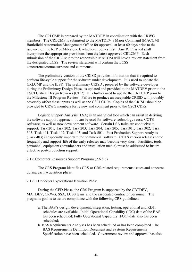
The CRLCMP is prepared by the MATDEV in coordination with the CRWG members. The CRLCMP is submitted to the MATDEV’s Major Command (MACOM) Battlefield Automation Management Office for approval at least 60 days prior to the issuance of the RFP or Milestone I, whichever comes first. Any RFP issued shall incorporate the appropriate provisions from the latest approved CRLCMP. Each submission of the CRLCMP to the responsible MACOM will have a review statement from the designated LCSS. The review statement will contain the LCSS concurrence/nonoccurrence and comments. The preliminary version of the CRISD provides information that is required to perform life-cycle support for the software under development. It is used to update the CRLCMP and the ILSP. The preliminary CRISD , prepared by the software developer during the Preliminary Design Phase, is updated and provided to the MATDEV prior to the CSCI Critical Design Reviews (CDR). It is further used to update the CRLCMP prior to the Milestone III Program Review. Failure to produce an acceptable CRISD will probably adversely affect these inputs as well as the CSCI CDRs. Copies of the CRISD should be provided to CRWG members for review and comment prior to the CSCI CDRs. Logistic Support Analysis (LSA) is an analytical tool which can assist in deriving the software support approach. It can be used for software technology reuse, COTS software, as well as new development software. Certain LSA tasks are conducive to support; Task 201; Task 202; Task 203; Task 204; Task 205; Task 301; Task 302; Task 303; Task 401; Task 402; Task 403; and Task 501. Post Production Support Analysis (Task 403) is especially important for commercial software. COTS version releases come frequently and support life of the early releases may become very short. Facilities, tools, personnel, equipment (downloaders and installation media) must be addressed to insure effective post-production support. 2.1.6 Computer Resources Support Program (2.6.8.6) The CRS Program identifies CRS or CRS-related requirements issues and concerns during each acquisition phase. 2.1.6.1 Concepts Exploration/Definition Phase During the CED Phase, the CRS Program is supported by the CBTDEV, MATDEV, CRWG, SSA, LCSS team and the associated contractor personnel. The programs goal is to assure compliance with the following CRS guidelines: a. The BAS’s design, development, integration, testing, operational and RDIT schedules are available. Initial Operational Capability (IOC) date of the BAS has been scheduled; Fully Operational Capability (FOC) date also has been scheduled; b. BAS Requirements Analyses has been scheduled or has been completed. The BAS Requirements Definition Document and Systems Requirements Specification have been scheduled. Government review and approval has also

45
been scheduled; c. The BAS requirements analysis and design/development processes and their progress visibly will be provided and available for the System Hardware and Software Requirements Analysis, and the Preliminary and Critical Hardware and Software Design Reviews; d. Software program development will facilitate life-cycle maintenance (i.e., modifications and RDIT). Structured, repeatable, testable and evaluable software environments methods and techniques will be used and enforced (i.e., analysis, top-down design, development, and documentation) throughout software development and support; e. All levels of maintenance for the DSSE and LCSSE will be provided by the design/development contractor and the Government, respectively. 2.1.6.2 Concept Demonstration and Validation Phase During the CDV Phase, the CRS Program continues to be supported by the CBTDEV, MATDEV, CRWG, SSA, LCSS Team and the associated contractor personnel. The program’s goal is to assure compliance with CRS guidelines: a. BAS’s schedules are still valid. If modified, IOC and FOC scheduled dates can still be met (See paragraph 2.6.1.a.); b. The completed and dated Developmental Software Support Environment Plan (DSSEP), Software Support Transition Plan (SSTP) and Life-Cycle Support Guide provide detailed descriptions of the CRS requirements and capabilities for the BAS program. Government review and approval dates have been scheduled. The demonstratability and validity of the of the BAS System/ Segment Hardware, Firmware and Software Development and Product Specifications is a strict function of the quality of effort to prepare and review this documentation; c. Progress/status reports have been made available and used for system and design reviews (See paragraph 2.6.1.c); d. Structured software environments have been used throughout software development (See paragraph 2.6.1.d); e. The contractor has demonstrated a capability to support and sustain the developing software (See paragraph 2.6.1.e). 2.1.6.3 Engineering and Manufacturing Development Phase During the EMD Phase, the CRS program continues to be supported by the CBTDEV, MATDEV, CRWG, SSA, LCSS Team and the associated contractor personnel. The programs goal is to assure compliance with CRS guidelines:

46
a. BAS schedules are still valid; IOC and FOC scheduled dates can still be met (See paragraph 2.6.1.a); b. The DSSEP, SSTP, and Life-Cycle Software Support Environment Guide are still valid documents (See paragraph 2.6.2.b); c. The BAS program’s CRS evaluations and process/status reports continue to be used to validate BAS supportability. The developmental and life-cycle support systems will apply “best” quality assurance/control and configuration management methods and tools; d. Structured software environments continue to be used for system and design reviews (See paragraph 2.6.1.d); e. The contractor continues to demonstrate a capability to support and sustain the developing software (See paragraph 2.6.1.e). 2.1.6.4 Production and Deployment Phase During the Production and Deployment Phase, the CRS program continues to be supported by the CBTDEV, MATDEV, CRWG, SSA, LCSS Team and the associated contractor personnel. The program’s goal is to assure compliance with CRS guidelines: a. The BAS’s production model is proven supportable, at least 60 days before it is to be deployed; . b. The BAS’s production model has proven itself operational; c. The operational performance envelope of the BAS is of sufficiently high quality; d. The demonstration of the LCSSE and the LCSSTE capability precedes the deployment by at least 45 days; e. Both IOC and FOC schedule dates can be met; f. The BAS program CRS process evaluations and progress/status reports have been used to validate supportability; g. Software program supports life-cycle maintenance and RDIT; h. All levels of maintenance of the LCSSE will be provided by support software and the computer resources transferred from DSSE. 2.1.7 Organizations with ILS Responsibilities for Computer Resources Support (2.6.8.7) The organizations responsible for CRS are the CBTDEV (user representative), MATDEV, RC, SED/SSA, and the CRWG. Computer resources logistic support is required throughout the programs acquisition phases. 2.1.7.1 Combat Developer The Combat Developer (CBTDEV) is the ILS program manager for the acquisition program before Milestone I or prior to PM designation. The CBTDEV, ILS manager, logistician and other ILS participants coordinate pre-Milestone I ILS activities. The

47
CBTDEV provides field information to develop ILS program objectives and requirements. The CBTDEV, as field user representative, determines system requirements. Specifically, the CBTDEV determines when the system is required, and defines and maintains the tactical, functional, operational, and operability requirements baseline. 2.1.7.2 Materiel Developer The Materiel Developer (MATDEV) is technically responsible for the CRS for the acquisition and initial fielding of the BAS. The MATDEV is charged with technology-related and equipment-related acquisition/procurement, research and development, Configuration and Data Management (CM and DM), Development Tests (DT), evaluation, ILS planning and execution, reliability, availability, maintainability, interoperability, production, New Equipment Training (NET), maintenance, storage, and disposal for the BAS. The PM is the focal point between the MATDEV, the users, Readiness Command and the SED. The PM is responsible for implementing product improvements and fielding changes. MATDEV PDSS obligations include the development, maintenance, and execution of SED operations support plans; and technical guidance and assistance for software logistics support, software maintenance training, and technical testing. 2.1.7.3 Readiness Command After transition the Readiness Command (RC)is responsible for development and CRS of the BAS. Post-deployment CM is the RC’s responsibility, but software CM is performed by the designated SED. The RC provides direct field support and depot support (through the National Inventory Control Point [NICP])to the BAS RC materiel manager and the TRADOC doctrinal center. The RC’s Logistics and Maintenance Directorate (LMD) identifies fielded BAS software problems. Logistics Area Representatives (LAR) also assist site personnel find and report fielded BAS malfunctions. The National Maintenance Point (NMP) controls software problem reporting. The NMP is part of the RC but not part of the LCSS facility. For a fielded BAS, the reporting documents are the Equipment Improvement Recommendation (EIR) and the Quality Deficiency Report (QDR). The NMP transmits information copies to the CBTDEV, MATDEV, and theSED/SSA. The RC may use other reports (e.g., Software Trouble Report [STR] Software Problem/Change Report [SP/CR], and the Problem Identification Report [PIR]). After the SED/SSA has solved the problem, the solution must be approved by the Software Configuration Control Board (SCCB); and pass certification, verification and validation, product assurance and user tests. Development Test (DT) or OT II test may be required if the modifications are sufficiently complex, extensive or express doctrinal changes. The software adaptations, corrections, and perfection’s will be consolidated into a Software System Version Materiel Release. The NMP will coordinate the release RC’s System Manager and Concurrent Engineering Directorate (CED). Program Executive Office (PEO)/PM may also coordinate with SED/SSA’s fielding of the software release.

48
2.1.7.4 Software Engineering Directorate The Software Engineering Directorate (SED) is responsible to the PM for providing inputs to ILS and LSA requirements. The SED must ensure that the plans for CRS are appropriate, comprehensive and properly executed. The SED shall provide a representative to the Integrated Logistics Systems Management Teams (ILSMT). Further SED shall contribute to the Logistic Support Analysis Record (LSAR) and to the Materiel Fielding Plan (MFP). The SED shall coordinate with the National Management Point (NMP) and the NICP for the BAS to ensure that appropriate procedures for field support are available and applied to the first unit fielding(s). During PDSS, the SED and PEO/PM receive information copies of software problem reports. Software problems are forwarded to the SED for analysis and resolution. SED convenes the SCCB to evaluate and prioritize problems. After software modification is accomplished, it is tested. The SED verifies and validates the resultant solution before the release of the proposed version to the MATDEV for final system testing. If only the documentation changes, there is no need for extensive verification and validation. A sufficient set of verification/validation topics will include: operational, procedural and maintenance process inspections; man-machine interfaces; process walkthroughs; regression checking; and error handling. SCCB modification approval is followed by MATDEV-performed/CBTDEV- monitor certification testing. User testing is a TRADOC responsibility. The NMP coordinates the modification with CED. SED then enters the approved software version in the Software Configuration Management Baseline. The PEO/PM coordinates with software version fielding. The SED is also responsible for the establishment and enforcement of software licenses, warranties and assurances specified the development or production contract. The Government will pursue, obtain, exercise, and defend the following: a. Rights or limited rights over target and host BAS software; b. A software escrow account for disclosure on non-standard hardware and firmware configurations. Disclosure includes the identification and provision of, or access to the documentation and tools required to replace system items, without expending design efforts. Escrowed documentation and drawings need not be updated beyond the product baseline of the engineering and manufacturing contract. 2.1.7.5 Software Support Activity The SSA is the key software support participant. The activities and responsibilities of the SSA evolve from pre- to post-deployment software support. The SSA’s primary

49
responsibility is to be the Government agency tasked to provide: PDSS requirements to the PM; and cost effective PDSS planning , management and operations. Pre-deployment software support focuses on ensuring supportability and planning for cost effective PDSS. SSA PDSS activities further ensures supportability, manages PDSS and conducts efficient PDSS operations. The SSA role in support of the PM, evolves with the acquisition process and software support stages. During pre-deployment, SSA concerns include plans, require-ments, identification, quality, supportability and transition. During post deployment, the SSA concentrates on change implementation (i.e., conducting PDSS operations in accordance with the approved PDSS concept) and maintenance of software and technical data quality at acceptable costs. The SSA charter specifies the responsibilities. 2.1.7.6 Computer Resources Working Group The PM establishes the CRWG to prepare, review, and coordinate the CRLCMP. The CRWG manages oversight of the BAS’s CRS. The CRWG uses the CRISD to update the CRLCMP prior to each Milestone Review. The ILSP should contain the date the CRWG was chartered as well as the office initiating the charter. The CRWG charter is an appendix to the CRLCMP. The CRWG membership is composed of a chairperson from the MATDEV and members from the CBTDEV, the SED, the testers and evaluators, CED , US Army Materiel Command (USAMC) and the prime contractor. 2.1.8 Computer Resources Integrated Logistic Support Requirements (2.6.8.8) The requirements are divided into two sets, operational and maintenance. Operational requirements address the tasks performed to support the development, test, transition, modification and RDIT of the system. Maintenance requirements refer to the tasks performed to keep the development, test, transition, operational and PDSS systems functional and operational. 2.1.8.1 Operational Requirements The pre-deployment CRS operational requirements apply to system computer resources design, development, and testing and evaluation support. The development contractor(s) shall use approved management, engineering, quality control, and configuration management procedures. The process software design, development, and testing will be based on the structured methodology and criteria of the Software Engineering Institute’s Software Capability Evaluation. Mission and support hardware design, development, testing, and manufacturing will be conducted using “best” and Government approved methods, techniques and tools.

50
Operational software documentation will provide technical descriptions and operational and diagnostic instructions for the BAS, and the contractor’s Software Development and Maintenance Facility (SDF and SMF). The SDF and the SMF will provide the SED with the training and documentation to support the BAS upon its transfer. The contractor will execute the entire STrP to transfer the contractor’s SDF/SMF hardware, software and documentation to the SED/SSA. The contractor will perform the pre-transition, transition and post-transition procedures detailed in the subsequent paragraphs. a. Pre-Transition Stage During the pre-transition stage the BAS Manager will work closely with the Contracting Officer’s Technical Representative (COTR) to ensure that all transitional procedures and activities are approved by the COTR. The major pre-transition stage procedures include: (1) Study the SED/SSA to ensure that it can adequately host the BAS support software and make recommendations for any necessary augmentation; (2) Submit for Government approval and disposition of the following: instructions for the extraction from the contractor’s development and maintenance facilities and installation into the SED/SSA; identification of the contractor’s inventory of hardware, software and associated documentation which is unnecessary for the functioning of the software maintenance facility; (3) Upon receipt of approval from the Government, ship the hardware, software and the associated documentation to the designated site(s) using pre-approved means of transportation; (4) Assure that the computer system and peripherals, configured at the SED, are adequate to host and support the BAS’s maintenance and test software; (5) Establish instructions to reinforce, rebuild and test the BAS’s maintenance software; (6) Establish instructions that assure safe shipment and “checkout” of hardware, software and documentation to the designated site(s). b. Transition Stage During the transition stage, the hardware software and documentation of the SMF will be transferred to the facilities designated by the Government. Procedures for the transition include: (1) Replicate all software required to rebuild the BAS and its support system at SED/SSA; (2) Rebuild the system and it’s support system at the contractors SMF to verify the rebuild procedure;

51
(3) Test the rebuild to ensure that the “as-build” system is indeed the LCSS system needed to support the BAS; (4) Arrange for a contractor to extract the objective and support system from the development facility and re-install these systems at the SED/SSA; (5) Package the equipment, software and documentation according to the best commercial practices; (6) Ship the hardware, software and documentation to the government designated site(s). c. Post-Transition Stage During the post-transition stage, contractor engineers will be available to the Government to ensure proper operation of the LCSS system. The following procedures will be performed: (1) Install the necessary hardware at the SED/SSA site(s); (2) Install the BAS software and associated commercial or independently developed packages on the SED/SSA’s system; (3) Train the Government personnel to support the maintenance and test software at the SED/SSA facility; (4) Certify identified Government Personnel’s ability to operate the BAS maintenance and test software at the SED/SSA site(s); (5) Review and approve/disapprove the documentation and support procedures (at SED/SSA) for the generation, installation, operation, test and support of all the contractually deliverable BAS and support system software. 2.1.8.2 Maintenance Requirements Maintenance policies and procedures will have been identified through LSA and documented in the LSAR. Maintenance requirements will evolve through the acquisition phases. The software contractor’s SMF will enable development and maintenance personnel to update, correct, enhance, replicate, and review the BAS software. The contractor will perform hardware and software adaptive, corrective, preventive, and perfective SDF and SMF activities. The BAS will be supported by embedded or portable Automatic Test Equipment (ATE) within which Test Program Sets (TPS) reside for maintenance testing and support. Although , perhaps developed by other than the developmental contractor, the TPSs will be considered an integral component of the BAS acquisition program. The TPSs will be acquired (i.e., developed, tested, evaluated documented, certified, and accepted), in the same manner as the BAS’s operational and other support software, by the organization that the PEO/PM deems appropriate (e.g., LMD, CED or SED). The support software for the TPSs will be transitioned from the TPS developer to the LCSSE or LCSSTE, as appropriate. The transitioned software must be tested, certified, and accepted before responsibility for its function is transferred to a Government office.

52
a. Pre-Deployment Stage The contractor will plan and perform computer resources maintenance activities at the SDF and the SMF prior to BAS transition to the SED. The contractor will provide the SED with a Maintenance and Documentation Package. This package will be either a consolidation of documentation and necessary software, firmware and hardware tools and instructions; or an originally designed, developed and tested Maintenance System Package with TPSs. The package will enable SED/SSA personnel to duplicate, rebuild and test the system’s maintenance software. The contractor will identify and /or provide sufficient training for SED/SSA personnel to support and maintain the BAS software. The SED/SSA and the contractor will assess contractor and SED/SSA facilities to determine the ability of the SED/SSA to attain BAS supportability. Equipment and software support systems, or major subsystems, requiring introduction, exclusion additions, conversion, modification or replacement will be identified and resolved accordingly. b. Transition Stage The SED/SSA and the contractor will execute the STrP and follow the procedures described in paragraph 2.8.1.b. c. Post-Deployment Stage The contractor and SED/SSA will execute the PDSS Plan, follow the procedures described in paragraph 2.8.1.c. 2.1.8.3 Computer Resources Limitations The SED , contractor and MATDEV will investigate and determine the constraints on host development, target and support computer systems’ capabilities. Several types of computer resource limitations include: a. Acquisition cost and schedule; b. Available personnel, skills, equipment and software resources; c. Available system, support and maintenance platform space versus implemental computer platform size; d. Available computer memory versus required storage capacity; e. Display limitations (e.g., dimensions, illumination); f. Ability to use vast databases and/or complex algorithms; g. Ability to locally and/or globally computer network; h. Enforcement of operational, support and maintenance simplicities to minimize costs and skill requirements; i. Utilization of available support resources; j. Overload of SED personnel with multiple systems to support.

53
2.1.8.4 Security Requirements and Controls Security requirements and controls will be applied to each of the computer resources support stages. Pre-deployment design, development, test and evaluation activities and products; and transition and PDSS environment hardware and software components may require security control. Contractor activities shall be in accordance with DOD Industrial Security Manual for Safeguarding Classified Materiel (ISM). A software security analysis shall be performed to determine the necessity, depth, breadth and sufficiency of security requirements for the system acquisition, transition, fielding , operation and post deployment support. The Software Security Analysis Report shall be available with the RFP, completed before the contract is awarded, and updated throughout the life-cycle of the system. The Software Security Analysis Report will cover each acquisition activity and product. The result of the software security analysis and other specific security classification guidelines will be input into the Program Security Classification Guide of the Contract Security Classification Specification. 2.1.9 Software Documentation (2.6.8.9) The System’s pre-deployment software will be documented in accordance with the requirements analysis and definition, design, development, test and evaluation, production, transition and fielding contract stipulations. The post-deployment software will be provided by the SED (or its support contractor in accordance with established policy). A list of the required documents is shown in Table 2-1. The composition and function of each deliverable document will be based on the Contract Data Requirements List (CDRL) and Data Item Description (DID). This documentation will be maintained by the software contractor and SED during the pre- and post-deployment stages, respectively. The documentation will be stored in the software library established by the CM activity (e.g., Software Configuration and Reference Office[SC&RO]). This library may also be required to store classified data. A change in the specifications or an enhancement to the software may cause some of the documents to change. Modified documentation will be stored in the software library while earlier versions will be archived in a history file. 2.1.10 Software Support Environments (2.6.8.10) Software systems require support environments for development, maintenance (i.e., adaptation, correction and improvement), and RDIT. The pre-deployment stage is supported by the DSSE , reference MIL-STD-1467(AR) and MIL-HDBK-782(AR). The DSSE is usually managed by the prime software contractor. The DSSE is used to develop and control the contractually deliverable software. The DSSE typically applies a host/target computer systems methodology, comprised of a defined set of user/system interfaces, an integrated architecture of software tools, and a central library for the

54
configuration management and access to all information associated with the development and support of the contractually deliverable software. The software transition stage is supported by both the DSSE and the LCSSE. The post-deployment stage will be supported by the LCSSE (same reference as above). The LCSSE is the portion of the software support environment, managed by the SED/SSA, that will be used to provide post-deployment support of the contractually deliverable software. The LCSSE will be composed of a centralized host computer or a minicomputer sharing program environment services on a Local Area Network (LAN) with target system peculiar assets and a shared mainframe-based configuration management library. Concise descriptions of the DSSE or LCSSE should be provided; if not currently available, an estimate should be provided of when the description will be available.

55
TABLE 2-1 SOFTWARE DOCUMENTATION
System/Subsystem Design Description (SSDD) System/Subsystem Specification (SSS) Software Development Plan (SDP) (Preliminary) Software Requirements Specifications (SRS) (Preliminary) Interface Requirements Specification (IRS) (Preliminary) Software Design Description(s) (SDD) (Preliminary) Interface Design Description(s) (IDD) Software Version Description (SVD) DataBase Design Description (DBDD) Computer Resources Life-Cycle Management Plan (CRLCMP) Computer Resources Integrated Support Document (CRISD) Software Configuration Management Plan (SCMP) Software Support Plan (SSP) Test and Evaluation Management Plan (TEMP) Software Test Plans, Procedures, Descriptions and Reports Software or System Training Plan Software and System Training Documentation Software Transition Plan (STrP) Software Fielding Plan(s) (SFP) (Preliminary ) Software Users Manual (SUM) Computer System Operators Manual (CSOM) Firmware Support Manual (FSM) Technical Manuals (TM) Commercially Available Software documentation Privately Developed Software Documentation Government Publications DSSE Software Maintenance Documentation LCSSE Software Maintenance Documentation

56
Left Blank

57
CHAPTER 3 MODEL LIFE CYCLE SUPPORT SECTION
OF THE COMPUTER RESOURCES LIFE-CYCLE MANAGEMENT PLAN
3.0. OVERVIEW 3.0.1 Computer Resources Life-Cycle Management Plan The Computer Resources Life-Cycle Management Plan (CRLCMP) addresses the requirements for computer resources of the subject system over the entire development and operational life cycle. All software to be developed or modified and all related major tasks ,such as Replication, Distribution, Installation and Training (RDIT), shall be described. Development and support organizations (Army and contractor shall be identified and responsibilities defined). The CRLCMP describes the required disciplines such as configuration management, product assurance, testing and software support as they apply to the system. Guidance for the preparation of the CRLCMP can be found in AMC-R 70-16, Management of Computer Resources in Battlefield Automated Systems, and Army Materiel Command Memorandum, Interim Operating Instruction (IOI) for Preparing Computer Resources Life Cycle Management Plans. 3.0.2 Applicability The CRLCMP, as a stand alone document, can also be used as an annex to the Acquisition Plan, Program Management Plan, Integrated Logistic Support Plan (ILSP) or the Test and Evaluation Management Plan. The CRLCMP shall be maintained current throughout the system life cycle as requirements change. 3.0.3 Organization of the Computer Resources Life-Cycle Management Plan The CRLCMP contains four sections: Section I, General; Section II, Acquisition and Development; Section III, Assessment; Section IV, Life Cycle Support. 3.1. GENERAL (SECTION I) This section provides an overview of the overall system requirements including simulators, trainers, and test installation; and their relationship to the proposed computer resources. Any unique operational or technical system requirement that could affect the development or use of the proposed computer resources should be covered. This section also lists the organizations and working groups that are actually participating in the management of computer resources for the system, with a brief description of their computer resource responsibilities. 3.1.1 Introduction (I.A)

58
3.1.2 System CRLCMP Maintenance (I.B) 3.1.3 Applicable Documents (I.C) 3.1.4 Definitions (I.D) 3.1.5 Acronyms and Abbreviations (I.E) 3.1.6 System Description (I.F) This section will summarize the mission and major functions of the operational system. It identifies the operational needs, purpose, and applications to be satisfied by the system. This description should include a simple illustrative functional diagram of the system. It should also identify the Computer System Configuration Items (CSCI) proposed for the system. The Computer Program Media (CPM) and/or program load media should also be identified. The acquisition or design approach may preclude early identification of the CSCIs or the CPM. 3.1.7 Computer Resource Issues (I.G) 3.1.8 Participating Organizations and Working Groups (I.H) This section will list the organizations and working groups which are actively participating in the management of computer resources for the system with a brief description of (or reference to) their major computer resources responsibilities. 3.1.8.1 Software Engineering Directorate The Software Engineering Directorate (SED) is the single command focal point for all the system computer software resource activities. SED is designated by the Program Manager (PM) to act as the surrogate during predeployment for all computer software employed in the system. In general, SED is the computer resource manager for software resources to include: Operating systems; Utilities; Database systems; Computer language; Software and firmware media. 3.1.8.1.1 SED Management Support SED is responsible for providing management assistance. In coordination with the system development activity and the combat developer, assists in specifying responsibility for maintaining and modifying the system computer resources. It provides membership to the system Computer Resources Working Group (CRWG), Test and Integration Working Group (TWIG), Configuration Control Board (CCB), Source Selection Evaluation Board (SSEB), system reviews and other management activities. It provides the system PM with a review statement indicating the concurrence of SED with the system CRLCMP. It

59
further participates in the preparation and award of the contract by performing the following activities: a. Participating in the Request for Proposal (RFP) preparations, proposal evaluation, and source selection; b. Assisting in the preparation of the Statement of Work (SOW), Contract Data Requirements List (CDRL), Baseline Cost Estimate (BCE), project management documents, contracts and associated specifications, and contracting strategies; c. Reviewing solicitations/RFPs for system computer resources prior to issuance, and providing concurrences; d. Participating in the system SSEB, contract negotiations, and pre-award survey. 3.1.8.1.2 SED Technical Support SED is responsible for providing technical assistance by performing the following activities; a. Developing and adapting methodology to improve the system computer design, acquisition and management processes in order to reduce overall system cost and to improve software activity; b. Examining the system CRLCMP for the analysis and justification of deviations from the requirements for the target system’s High Order Language (HOL) and for reviewing Ada waivers; c. Ensuring the standardization of computer equipment, computer program media, replication and/or downloading equipment, software and support facilities; d. Performing engineering software evaluations in order to ensure functionality, traceability, and supportability; e. Making recommendations regarding system design features that enhance ease of support , operation, and training; f. Identifying potential computer resource problems that affect supportability, and recommending design and schedule trade-offs that can avoid or minimize such problems; g. Performing system computer resource design, development, documentation, configuration and data management, and testing functions in response to changes. 3.1.8.1.3 SED Post Deployment Software Support SED is responsible for providing Post Deployment Software Support (PDSS) by performing the following activities; a. Providing the PM with the necessary information to determine the resource needs of SED for post deployment support of the system; b. Determining the system supportability throughout the system life cycle;

60
c. Identifying and developing new support software, tools and components if required; d. Assisting the PM in applying the principles of Integrated Logistic Support (ILS) to all software development and software logistic support; e. Approving support software documentation required to support the system computer resources over the system life cycle; f. Designing and implementing; software product tests; software versions and documentation; version control; and software release coordination; g. Providing advice and assistance to perform RDIT for software changes. 3.2. ACQUISITION AND DEVELOPMENT (SECTION II) This section addresses the computer resource acquisition strategy, as well as the participation of the combat developer, acquisition manager, Test and Evaluation (T&E), and the designated Life Cycle Software Engineering Center (LCSEC). This section is prepared by the acquisition manager in coordination with the Computer Resources Working Group (CRWG). It includes the management planning for the acquisition and development of the computer resources. It addresses the management approach, decisions, as well as plans for the development of computer resources, tools to be used, necessary facilities, costs and schedules. It identifies the actions necessary for the development and delivery of computer software and the necessary support resources, to include software media replicators and downloaders used in RDIT. 3.2.1 Computer Resources Acquisition Strategy (II.A) The acquisition methods and approaches described in this section will impact on how software is to be supported during PDSS and the timing for support/logistics decisions. Examples of acquisition methods are competitive development, “in house” development, Nondevelopmental Items (NDI), Pre-Planned Product Improvement (P3I), and Military Adaptation of Commercial Items (MACI). 3.2.2 Program Schedules and Funding (II.B) This section should identify the funding levels for contracts, equipment for the LCSEC, product assurance, and LCSEC personnel. 3.2.3 Computer Resources (II.C) This section will identify the target computer system(s) and the elements of the Developmental Software Support Environment (DSSE). MIL-HDBK-347 “Mission Critical Computer Resources Support” can provide criteria for the identification of the required computer resources.

61
3.2.3.1 Target Computer System(s) (II.C.1) This section should identify the specific hardware configuration that will be employed. Depending on system requirements, the configuration might be fully specified by the Government with no contractor options, or the contractor may be permitted to recommend a configuration. It should also describe eraseable firmware, operational software, computer program media (e.g., tape, disk, diskette, microdiskette, etc.) and documentation. 3.2.3.2 Elements of the Developmental Software Support Environment (II.C.2) The DSSE elements will include the host computer system, hardware, support software, documentation, test support, simulation tools, or models. The information should include whether the contractor will develop a Software Development Facility (SDF) and a Software Maintenance/Support Facility or use an existing or Government facility. It should further indicate if the Government will establish a facility for a designated Software Support Activity (SSA); if so, where will it be located, who will operate it, and how will it be acquired. 3.2.3.3 Life Cycle Software Support Environment (II.C.3) The Life Cycle software Support Environment (LCSSE) includes the host computer system; hardware; operational, maintenance, test and support software suites; replication equipment; software downloader/memory loader verifier; documentation; test support or simulation tools. 3.2.4 Standardization and Commonality and Reusability (II.D) One of the items to be addressed is the requirements analysis to identify potential reusable assets and the process for their acquisition, implementation and use. 3.2.5 Software Metrics (II.E) This paragraph describes how software metrics (to include RDIT metrics) will be used in the decision -making process. Software development metrics can be applied to software maintenance during PDSS. 3.2.6 Risk Management (II.F) System design analysis and trade-off considerations are usually identified in the system specifications. Additional studies can be conducted to identify the risks associated with media choice (especially firmware). Selection of any media should consider the effects on readiness and cost risks for fielding subsequent versions. 3.2.7 Design Methodology (II.G)

62
Specific design practices are contained in DOD Instruction 5000.2, Part 6, Section D.1.b(9). Infusion of PDSS concerns in the requirements and design considerations will ensure that RDIT can be effectively and efficiently implemented 3.2.8 Throughput and Reserve Margins (II.H) 3.2.9 Risk Area Identification (II.I) 3.2.10 Security and Virus Protection (II.J) 3.3. ASSESSMENT (SECTION III) This section will address computer resources test/evaluation and software quality issues in the system. It contains a plan and schedule for insuring a quality product and for development of plans for testing. Preparation of this section will be coordinated with the Test Integration Working Group (TWIG) and Product Integrity and Production Engineering (PIPE) (e.g., product assurance, producibility, reliability, and maintainability) element during all phases of the life cycle. Supporting data will appear in the Test and Evaluation master Plan (TEMP). This section also identifies plans for implementing Total Quality Management (TQM). 3.3.1 Test Requirements (III.A) This section should include a plan for the conduct of the supportability demonstration of the PDSS facilities. The supportability demonstration plan will delineate and specify requirements for the testing and methodology to be used to verify compliance with the requirements. The demonstration will exercise the support capability, to include downloading/verification, in real time to permit assessment and certification of its adequacy for the post deployment phase. 3.3.2 Total Quality Management (III.B) 3.4. LIFE CYCLE SUPPORT (SECTION IV) This section addresses the issues of computer resource support, to include RDIT, particularly software after deployment. Included are paragraphs concerning software configuration management and management responsibility transfer. MIL-STD-498, Software Development and Documentation; DoD-STD-1467 (AR),Military Standard Support Environment; MIL-HDBK-782 (AR), Software Support Environment Acquisition; MIL-HDBK-347, Mission-Critical computer Resources Software Support can be employed and referenced in fulfilling these requirements. Data Item Descriptions (DID) can be found in the above references. 3.4.1 Participating Organizations (IV.A)
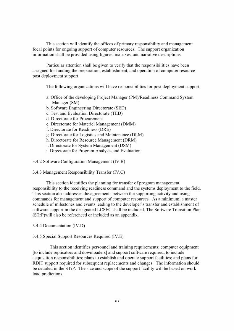
63
This section will identify the offices of primary responsibility and management focal points for ongoing support of computer resources. The support organization information shall be provided using figures, matrixes, and narrative descriptions. Particular attention shall be given to verify that the responsibilities have been assigned for funding the preparation, establishment, and operation of computer resource post deployment support. The following organizations will have responsibilities for post deployment support: a. Office of the developing Project Manager (PM)/Readiness Command System Manager (SM) b. Software Engineering Directorate (SED) c. Test and Evaluation Directorate (TED) d. Directorate for Procurement e. Directorate for Materiel Management (DMM) f. Directorate for Readiness (DRE) g. Directorate for Logistics and Maintenance (DLM) h. Directorate for Resource Management (DRM) i. Directorate for System Management (DSM) j. Directorate for Program Analysis and Evaluation. 3.4.2 Software Configuration Management (IV.B) 3.4.3 Management Responsibility Transfer (IV.C) This section identifies the planning for transfer of program management responsibility to the receiving readiness command and the systems deployment to the field. This section also addresses the agreements between the supporting activity and using commands for management and support of computer resources. As a minimum, a master schedule of milestones and events leading to the developer’s transfer and establishment of software support in the designated LCSEC shall be included. The Software Transition Plan (STrP)will also be referenced or included as an appendix. 3.4.4 Documentation (IV.D) 3.4.5 Special Support Resources Required (IV.E) This section identifies personnel and training requirements; computer equipment [to include replicators and downloaders] and support software required, to include acquisition responsibilities; plans to establish and operate support facilities; and plans for RDIT support required for subsequent replacements and changes. The information should be detailed in the STrP. The size and scope of the support facility will be based on work load predictions.

64
CHAPTER 4 MODEL SOFTWARE TRANSITION PLAN (STrP)
4.0. OVERVIEW 4.0.1 Software Transition Plan The Software Transition Plan (STrP) identifies the requirements, constraints, issues, processes, activities and computer resources necessary to provide the life cycle support of deliverable Battlefield Automated System (BAS) software. It plans for transitioning deliverable items from the development contractor’s or organization’s Developmental Software Support Environment (DSSE) to the life cycle Software Support Activity’s (SSA’s) Life Cycle Software Support Environment (LCSSE). Execution of this plan will warrant and ensure the existence, sustenance and maintenance of the LCSSE’s capability to perform computer resources support for the contractually deliverable software [i.e., mission operational, maintenance, configuration and data management, test, support, fielding (i.e., downloading/installation and delta-training), and security]. This plan also addresses the activities required to transfer necessary and excess hardware and firmware to the assigned LCSEC and delegated Army (or Joint) Depot repository, respectively. 4.0.2 Organization of the Software Transition Plan The STrP will have eight major sections as listed below: STrP Section Identifier STrP Section (Subsection) Title 1. Scope 2. Referenced documents 3. Software support resources 4. Recommended procedures 5. Training 6. Anticipated areas of change 7. Transition planning 8. Notes Appendix A Classified Information (as required) Appendix B DSSE Excavation Procedure (as required) Appendix C Transportation Procedure (as required) Appendix D LCSSE Installation Procedure (as required) 4.0.3 Software Transition Plan Data Item Description The format and content preparation instructions for the STrP are provided in the Data Item Description (DID) DI-IPSC-81429. Additional instructions and guidance are presented in the following sections.

65
4.1. SCOPE (1.) This Software Transition Plan (STrP) applies to the transfer of deliverable software/firmware and software/firmware support resources from the development contractor’s (or organization’s) Developmental Software Support Environment (DSSE) to the life cycle Software Support Activity’s (SSA’s) Life Cycle Software Support Environment (LCSSE). 4.1.1 Identification (1.1) 4.1.2 System Overview (1.2) 4.1.3 Document Overview (1.3) 4.1.4 Relationship to Other Plans (1.4) This section shall describe the relationship, if any, of the STrP to other project management plans, such as the Computer Resources Life Cycle Management Plan (CRLCMP) and the Software Fielding Plan (SFP). 4.2 REFERENCED DOCUMENTS (2.) 4.3 SOFTWARE SUPPORT RESOURCES (3.) This section identifies and describes the resources necessary to: analyze, specify, design, implement, document, and test and evaluate operational software modifications; and configuration control, materiel release and field (i.e., copy, distribute, install and delta-train) the operational software and the associated user documentation and training information. 4.3.1 Facilities (3.1) This paragraph shall describe the facilities required to support the deliverable software, such as a Software Maintenance Facility (SMF), a BAS Software Test Bed (SSTB) and/or Simulation Environment, and a Replication and Distribution Facility (RDF). These facilities may include special buildings, rooms, mock-ups, building features (e.g., raised flooring, dropped ceiling, cabling), (non-)secure communications and telecommunications facilities; building features to support security and privacy requirements (TEMPEST shielding, vaults, etc.), building features to support safety requirements (smoke alarms, safety glass, etc.), special power requirements, etc. The purpose of each item shall be described. Diagrams may be included, as applicable. 4.3.2 Hardware (3.2)

66
This paragraph identifies and describes the hardware and associated documentation required to support the deliverable software. This hardware may include computers, peripheral equipment, computer network assemblies, hardware simulators, stimulators, emulators, sensor/weapon system/communications device or virtual prototype (“mock-up”) equipment, data acquisition equipment, analog-to-digital (A/D) and D/A data conversion equipment arrays, analog and digital processing and analysis equipment, tactical communications equipment, test and diagnostic equipment, replication equipment, and software downloading equipment. The description shall include: a. Specific models, versions, and configurations b. Rationale for the selected hardware c. Reference to user/operator manuals or instructions for each item, as applicable d. Identification of each hardware item and document as acquirer-furnished, an item that will be delivered to the support agency, an item the support agency is known to have, an item the support agency must acquire, or other description. of status. (Note: if the item is redundant, excess or soon obsolete, its planned disposition should be provided) e. If items must be acquired, information about current sources of supply, including their current and delivery-time availabilities f. Information about manufacturers support, licensing and data rights, including:: whether the item currently supported by the manufacturer is expected to be supported at delivery-time, whether licenses will be assigned to the support agency and the terms and duration’s of such licenses; and whether there will be any data right restrictions and the terms and duration’s of those restrictions. g. Identification of any supportability-compatibility-interoperability issues h. Security and privacy considerations and limitations such as the necessity for security and corporate proprietary requirements for software maintenance and testing, software maintenance-related communications, replication, storage and handling, and distribution and downloading; or other items of interest 4.3.3 Software (3.3) This paragraph identifies and describes the software and associated documentation needed to support the deliverable software and firmware. This software may include computer-aided software engineering (CASE) tools (e.g., integrated software packages to provide the following capabilities: requirements and program analysis; system analysis and design; program and code analysis and design; development and implementation; code generation; test analysis, design, generation, performance, analysis and reporting, etc.), the data in these tools, compilers, test tools, test data, simulation software and data sets, emulation software and data sets, sensor/weapon system/communications device software, data acquisition software, analog and digital processing software, configuration interface software packages, metrics data acquisition and management software, utilities, configuration and data management tools, knowledge and data bases and files, downloading software. The description shall include:

67
a. Specific names, identification numbers, version numbers, release numbers, and configurations, as applicable b. Rationale for the selected software c. Reference to user/operator manuals or instructions for each item, as applicable d. Identification of each software item and document as acquirer-furnished, an item that will be delivered to the support agency, an item the support agency is known to have, an item the support agency must acquire, or other description of status (Note: Provide the planned disposition of redundant or obsolete items) e. If items must be acquired, information about current sources of supply, including their current and delivery-time availabilities f. Information about vendor support, licensing, and data rights, including whether the item is currently supported by the vendor is expected to be supported at delivery-time, whether licenses will be assigned to the support agency, the terms and duration’s of such licenses; and whether there will be any data rights restrictions and the terms and duration’s of those restrictions, if any. g. Identification of any supportability-compatibility-interoperability issues h. Security and privacy considerations and limitations such as the necessity for security and corporate proprietary requirements for operational, test, maintenance and support software; the classifications of source files, object files, data block and parameter block files; and the delegation of approved custody of proprietary software and software support. 4.3.4 Other Documentation (3.4) 4.3.5 Personnel (3.5) This paragraph describes the personnel needed to support: a. the transfer of physical computer resources from the DSSE to the LCSSE b. the deliverable software with these resources, at the LCSSE. The description will include the anticipated number of personnel, types and levels of skills and expertise, and required security clearances. This paragraph shall cite, as applicable, actual staffing on the development project, as a basis for the software support staffing needs cited. 4.3.6 Other Resources (3.6) 4.3.7 Interrelationships of Components (3.7) 4.4 RECOMMENDED PROCEDURES (4.)

68
This section shall be divided into paragraphs, as needed to describe any procedures, including advice and lessons learned, that the developer may wish to recommend to the support agency for supporting the deliverable software and associated support environment. 4.5 TRAINING (5.) This section shall be divided into paragraphs, as appropriate to describe the developer’s plans for training support personnel to support the deliverable software. This section will identify and describe which of the following types of training will be used: classroom training, self-paced, on-the-job-training/“hands-on” training. This section shall include: a. The schedule, duration and location for the training b. The identification of the course categories, such as the Managers’ Course and the Software Engineer’s/Programmer’s Course(s) c. General descriptions of the courses, including: (1) intended audience and maximal and/or minimal size of class (2) instructor/student ratio (3) required support (a) administrative (b) facilities (classroom configuration) (c) computer resources (types/numbers of workstations/equipment per student) (d) courseware, documentation and course materials (4) course descriptions (introduction, objective, and syllabi) d. Provision (either directly or by reference) for: (1) Familiarization with the operational software and target computer(s) (2) Familiarization with the support software and host system 4.6 ANTICIPATED AREAS OF CHANGE (6.) This section shall describe anticipated areas of change to the deliverable software and the LCSSE. Any requirements for additional training should be identified. The schedules of known and anticipated changes, and associated training may be provided, as required. 4.7 TRANSITION PLANNING (7.) This section shall be divided into paragraphs as needed to describe the developer’s plans for transitioning the deliverable software to the support agency. This section shall address the following: a. All activities to be performed to transition the deliverable software to the support agency. These activities may include financing/ budgeting, planning/ coordination meetings; preparation of items to be delivered to the support

69
agency; the DSSE Site Survey & Report; the LCSSE Site Preparation Plan & Procedures; packaging, shipment, installation, and checkout of the software support environment; packaging, shipment, installation, and checkout of the operational software; and training of support personnel. b. Roles and responsibilities for each activity c. The resources needed to carry out the transition activities and the source from which each resource will be provided d. Schedules and milestones for conducting the transition activities. These schedules and milestones shall be compatible with the contract master schedule. These schedules will include the periods during which facilities access, equipment and software transfer, transition demonstration and transition certification procedures will be allowed to occur. e. Procedures for the excavation of the computer resources (hardware, equipment software, and documentation to be transitioned from the DSSE to the LCSSE. f. Preparation of the computer resources for shipment. g. Procedures for installation and checkout of deliverable items in the support environment h. Training/certification of LCSSE support personnel i. Government Acceptance Test 4.8. NOTES (8.) Appendix A Classified Information Appendix B DSSE Excavation Procedure (as required) Appendix C Transportation Procedure (as required) Appendix D LCSSE Installation Procedure (as required)

70
CHAPTER 5 MODEL COMPUTER RESOURCES SUPPORT SECTION
OF THE MATERIEL FIELDING PLAN
5.0. GENERAL 5.0.1 Materiel Fielding Plan The Materiel Fielding Plan (MFP) serves as the single-stand-alone document containing the detailed plans and actions the fielding and gaining commands will accomplish to successfully field and deploy the materiel system. Much data in the MFP originate in source documents and the Integrated Logistic Support Plan (ILSP), but the MFP requires the most recent, complete, and accurate information. The Materiel Fielding Agreement (MFA)and subsequent agreements are appended to the MFP. Guidance for the preparation of the MFP can be found in DA PAM 700-142, Instructions for Materiel Release, Fielding and Transfer. 5.0.2 Organization of the Materiel Fielding Plan The MFP will have at least nine sections as listed below: MFP section Number MFP Section Title 1. Introduction 2. System Description 3. Fielding and Logistic Support Procedures 4. System Support Details 5. Readiness Reporting Requirements 6. Sample Data Collection 7. Support Required from Gaining Commands 8. Summary 9. Appendixes (Both required and optional) Software support information is included in the various sections; primary software support input can be found in paragraphs 4.3, Support Equipment and TMDE, and 4.11, Computer Resources Support. 5.1. INTRODUCTION (SECTION 1) This section states the purpose of the document and lists the data sources and agreements relating to the system and the fielding. 5.1.1 Purpose (1.1) 5.1.2 Data (1.2)

71
5.1.3 Agreements (1.3) 5.1.4 Fielding and Logistic Support Concept (1.4) 5.2. SYSTEM DESCRIPTION (SECTION 2) This section describes the physical and functional configuration of the system including all associated support, operational, and transport equipment for the system. It also states the category of Total Package Fielding (TPF) and the level of system complexity. 5.2.1 Functional and Physical Configuration (2.1) If a system is composed of multiple end items, each is summarized. Computer Program Material can be identified in this paragraph or in paragraph 5.11 of the MFP. 5.2.2 Associated Equipment (2.2) This paragraph identifies all associated equipment required to support the system. If downloaders/memory loader verifiers are required, the equipment should be identified in this paragraph or in paragraph 5.3.1 of the MFP. 5.2.3 Operational and Organizational (O&O) Plan (2.3) 5.2.4 Deployment Schedules (2.4) 5.3. FIELDING AND LOGISTICAL SUPPORT PROCEDURES (SECTION 3) This section includes command and control procedures, available logistics assistance, depot support, contractor support, and coordination for defects and problems. 5.3.1 Command and Control Procedures (3.1) 5.3.2 Logistic Assistance (3.2) This paragraph describes the types of assistance to be provided the gaining command including Logistics Assistance Representatives (LAR), New Materiel Introductory Briefing Team (NMIBT),New Equipment Training Team (NETT), and Materiel Fielding Teams (MFT). It identifies the LARs and/or contractor personnel to be stationed within the gaining command. If software assistance is to be provided by the LAR, paragraph 4.3.1 of the MFP should identify this paragraph and the individual/office providing support or assistance. 5.3.3 Depot Level or Contractor Support (3.3)

72
5.3.4 Material Defects Correction (3.4) 5.3.5 Coordination (3.5) 5.4.. SYSTEM SUPPORT DETAILS (SECTION 4) This section describes maintenance and supply support for the system. It is composed of a minimum of eleven paragraphs identified below . 5.4.1 Maintenance Plan (4.1) 5.4.2 Warranties (4.2) 5.4.3 Support Equipment and TMDE (4.3) 5.4.3.1 Computer Resources Support (4.3.1) Identify the following in this paragraph: a. The Life-Cycle Software Support Center(s) (LCSSC) for this system(s); b. The hotline telephone number for software support; c. The method to be used to change, replicate, distribute, install, and train for software changes; d. The downloading methods and media to be used for software changes; e. The Military Occupational Speciality (MOS)/personnel to perform the downloading and installation of the software changes; f. The frequency of change expected. 5.4.4 Supply Support (4.4) 5.4.5 Transportation and Transportability (4.5) 5.4.6 Packaging, Handling and Storage (4.6) 5.4.7 Technical Documentation (4.7) 5.4.8 Facilities (4.8) 5.4.9 Manpower and Personnel Requirements (4.9) 5.4.10 Training Equipment, Devices, and Aids (4.10) 5.4.11 Computer Resources Support (4.11)

73
In this paragraph identify computer hardware and software support required during the initial fielding to include; a. Computer Program Materials (CPM) to be provided at fielding (e.g., type of media and Computer Program Identification Number (CPIN) or version number; b. Describe the process for loading and acceptance of software during initial fielding; c. Personnel support required from gaining unit during the initial processing; Address post deployment software support procedures, requirements and responsibilities. Describe the process and procedure required to obtain replacement load and operational media; further identify Point of Contact (POC) and telephone number. The information provided in this paragraph and paragraph 4.3.1 of the MFP will depend on the complexity of the system and the software support required to support this system. This information may be included as an appendix to the MFP or may require a Post-Deployment Software Fielding Plan which may also be included as an appendix. 5.5. READINESS REPORTING REQUIREMENTS (SECTION 5) This section will state whether or not the system is readiness reportable as determined by Headquarters Department of the Army. It further identifies the pacing item for this system. 5.5.1 Reporting Requirements (5.1) 5.5.2 Readiness Reporting Data (5.2) 5.6. SAMPLE DATA COLLECTION (SECTION 6) Sample Data Collection (SDC) may or may not be required for the system under the provisions of AR 750-37. If required, a SDC concept paper is included as an appendix. 5.7. SUPPORT REQUIRED FROM THE GAINING MACOM(S) (SECTION 7) This section will define the administrative and operational support required from the gaining Major Command (MACOM) to accommodate system deployment and stationing of the materiel fielding personnel during the materiel fielding effort. It includes l facilities such as office space, class rooms, secure storage areas and other associated equipment. It also identifies special operational support such as labor, utilities or fuel. 5.8. SUMMARY (SECTION 8)

74
This section summarizes the status of logistic support for the system. It highlights major accomplishments, weaknesses and any significant issues to be resolved. 5.9. APPENDIXES (SECTION 9)

75
Left Blank

76
CHAPTER 6 MODEL POST-DEPLOYMENT SOFTWARE FIELDING PLAN
6.0 GENERAL 6.0.1 Software Fielding Plan The Software Fielding Plan describes the requirements, constraints, issues, process, activities, computer resources, staffing and facilities used to ensure the orderly and timely fielding of Battlefield Automated Systems (BAS) operational mission software/firmware after initial fielding and transition. The plan identifies the support to be provided by the software logistics support organization (e.g., Replication, Distribution, Installation and Training [RDIT]) and the gaining organization/units. It also defines the organizational responsibilities, frequency/schedule of upgrades, and the operational impacts on the using units. 6.0.2 Organization of the Software Fielding Plan The SFP will normally have five sections as listed below: MFP Paragraph Number SFP Section Title 1 Introduction 2. System Description 3. Fielding and Logistical Procedures 4. Post Deployment Software Support Details 5. Support Required from Gaining Command Only those paragraphs that are pertinent to the system should be included in the SFP; those paragraphs not required should be deleted. 6.1. INTRODUCTION (SECTION 1) 6.1.1 General (1.1) The Project Manager (PM) or Program Executive Officer (PEO) for the Battlefield Automated System (BAS) is responsible for the planning and coordination of software/firmware fielding. The PM/PEO is responsible for transitioning the BAS to the responsible readiness command (e.g., Communications-Electronics Command [CECOM]). After transition, the assigned Software Support Activity (SSA) (e.g., CECOM Software Engineering Directorate [SED]) will support system /item managers on matters relating to software/firmware.

77
6.1.2 Purpose (1.2) The Software Fielding Plan (SFP) provides information and guidance for all involved activities to ensure orderly and timely fielding of software/firmware changes after transition. This plan describes the organizational responsibilities, staffing, facilities equipment and procedures for the life-cycle mission support of each BAS. 6.1.3 Data (1.3) 6.1.3.1 References (1.3.1) The following references are applicable to a SFP: a. Integrated Logistic Support Plan (ILSP) for the BAS b. Computer Resources Life-Cycle Management Plan (CRLCMP) for the BAS c. Software Configuration Management Plan (SCMP) for the BAS d. Software Transition Plan (STrP) for the BAS e. SSA Replication, Distribution, Installation, and Training (RDIT) Standing Operating Procedures (SOP) f. SSA Identification SOP (e.g., CECOM SED Computer Program Identification Number [CPIN] Handbook). 6.1.3.2 Limits of Data (1.3.2) The data contained in a SFP is limited and based upon the information available at the time of publication. Updates will be published periodically or as required. Comments concerning the SFP should be submitted to the assigned readiness command. 6.1.4 Necessary Agreements (1.4) Agreements (e.g., Memorandum of Agreement [MOA] between Defense Logistics Agency [DLA] or a depot) required for software fielding will be identified in this paragraph; actual agreements may be appended to the document. These agreements are normally limited to a non-routine support process. 6.1.5 Scope (1.5) A SFP applies to the post-deployment software support, software fieldings, and resupply of the BAS software and firmware and the organizations that participate in those functions. 6.1.6 Participating Organizations and working Groups (1.6)

78
The normal participating organizations and working groups responsible for the management and execution of post-deployment fielding of the BAS software computer resources include: a. System Manager (e.g., PM/SM) b. Readiness Command Organizations (e.g., CECOM) 1. Software Engineering Directorate (SED) 2. Logistics and Maintenance Directorate (LMD) 3. Directorate of Materiel Management (DMM) 4. Directorate of Readiness (DRE) c. US Training and Doctrine Command (TRADOC) d. US Army Materiel Command (AMC) e. OPM Training Device (TRADE) of Simulation, Training and Instrumentation Command (STRICOM) f. Prime Contractor 6.1.7 BAS Software and Firmware Fielding concept (1.7) BAS software fielding, which includes software support and software readiness, is divided into three components: a. Initial fielding of the BAS software and firmware; b. Post-deployment fielding of new software and firmware versions; c. Media resupply of worn or damaged media (i.e. Winchester disk assemblies, Computer Disk-Read Only Memory [CD-ROMs], etc.) Post-deployment fielding and media resupply will be provided by the readiness command activity providing RDIT support. 6.1.7.1 Software and Firmware Fielding Process (1.7.1) The BAS software and firmware fielding process, in turn, is composed of the software materiel release process: a. The release of new software and/or firmware versions; b. Tracking the configuration of versions on the battlefield; c. The software resupply process. Once the software materiel release approval has been obtained for fielding, a hand-off of the master media to the SED occurs and RDIT support begins. During post-deployment software/firmware fielding, the maintenance process is employed when operational trouble, doctrinal change, or technological innovation force software/firmware change.

79
The initial deployment of BAS software is the responsibility of the PEO/PM in accordance with AR 700-142. The SED is responsible for providing support for this release. Subsequent software/firmware releases will be accomplished in accordance with AR 700-142 and AMC-R 700-34. 6.1.7.2 Replication Process (1.7.2) In post-deployment, the replication process loads the new program/version onto Computer Program Load Media (CPLM). The CPLM is then used to program the fielded BAS (e.g., Digital Audio Tape [DAT] , 3.5 inch magnetic or magneto-optical microdiskette, CD-ROM , etc.) Replication equipment for CPLM will reside in the SSA or preferably in a central SED RDIT support facility. The SED RDIT office support of the BAS replication process provides the following: a. Replication of Computer Program Media (CPM), hard disks and documentation; b. Reduction of facility space by eliminating duplicate equipment and storage of blank media; c. Readily available personnel; d. Economies of costs for media purchases; e. Process control support (i.e., scheduling, standard replication procedures, CPM identification and labeling , tracking and updates (i.e. CECOM Configuration Tracking System [CTS]), and after-action reports; f. Administration (i.e., identification labeling and Communications Security [COMSEC] requirements satisfaction). The initial firmware replication process will be performed by the development contractor. Eraseable Programmable Read-Only Memory (EPROM) board/bus or box/connector programmers will be used to program Printed Circuit Board(PCB)/Circuit Card Assemblies (CCA). For subsequent versions, the RDIT office will replicate master copies to be used with the prescribed Memory Loader/Verifier (MLV), i.e., downloader. In turn the master CPLM will be installed in the downloader to accomplish the installation of the new version . 6.1.7.3 Distribution Process (1.7.3) In software distribution, the CPM and the necessary support documentation are packaged as Computer Program Sets (CPS). The CPS Package includes: CPLM loaded with the new version software; technical documentation or changes; and instructions for program installation and media disposition (i.e., recovery or destruction); and receipt acknowledgment forms. The BAS PL identifies the appropriate documentation for replication and distribution (e.g., Technical Manuals [TM] installation instructions, training materiel, etc.). Each CPS is assigned and labeled with a CPIN. A distribution list of users, ordered by Unit Identification Code (UIC) and Major Command (MACOM), is provided by the RDIT tracking office (i.e., CTS).

80
Firmware distribution may be accomplished in several ways. A CPS is prepared for the new version and distributed to installation team(s) who provide on-site installation to the unit and maintenance spares. These teams can be trained and equipped by the centralized RDIT facility for subsequent travel to field sites or can be organized locally by the MACOM upon the receipt of the CPS. The PL may also establish a centralized RDIT facility to install the new firmware version on Large Replaceable Units (LRU)/CCAs or on EPROMs and distribute the upgraded firmware components to units who will replace them. The firmware CPS packages contain the same documentation as a software package. 6.1.7.4 Installation Process (1.7.4) The BAS software installation process updates the software version of the computer system. This process can be accomplished by the unit upon receipt of the CPS or by installation teams provided by the RDIT office. For simple version changes the instructions contained in the CPS are adequate for local installation. Complex changes may require installation team assistance or current delta- training and can best be accomplished by teams provided by the RDIT facility. Upon receipt of the CPS at the installation site, the installer/installation team will: a. Verify the completeness and integrity of the CPS; b. Load the new version software; c. Install the local parameters into the new software version; d. Perform a check-out test to verify and validate that the correct software package has been loaded and that the loaded package functions properly; e. Complete the installation report (e.g., Software Version Receipt Acknowledgment Form) to acknowledge the installation of the new package. After the new software version has been properly installed, the older software version CPM will be recycled or destroyed. A field user representative will be required to acknowledge receipt and installation. This receipt will be used to upgrade the tracking system (e.g., CTS). The BAS firmware installation process is a series of activities held at the RDIT facility or at designated installation sites. Distributed CPSs will contain installation instructions. An installation kit (including an EPROM eraser, a bulk EPROM reprogramming device, supplies, and tools and test equipment required by the process) will be used by the installer/installation team. The team and equipment is assembled and trained at the RDIT facility. A RDIT installation team can then be sent to designated sites to install the new version. A general flow of events include: a. The installation equipment is received, un-packed, checked-out, and assembled; b. The installation facility is organized; c. The installation team prepares a plan for the control the flow and upgrade of

81
new version installation; d. CCAs/LRUs are removed from equipment or maintenance storage areas for upgrade; e. Remove conformal coating, if necessary, erase and install new version, replace conformal coating; f. Install labels and CPIN onto the upgraded CCAs/LRUs; g. Incorporate local parameters into the new version; h. Perform a check-out test to verify and validate that the new version has been properly loaded and that the loaded CCAs/LRUs function properly; i. Complete the firmware version installation and acceptance report (e.g., CECOM Software Version Receipt Acknowledgment Form). If the EPROM’s can be removed from the boards, the team may arrive with an initial quantity of reprogrammed EPROMs and use the replaced EPROMs to continue the process. Should the EPROMs be loadable from the edge or from an external connector, the process would be modified as necessary. 6.1.7.5 Delta-Training Process (1.7.5) The delta-training process applies to post-deployment, new version software fielding only. Delta-training is neither New Equipment Training (NET), initial or refresher training. Delta-training focuses on changes in operations, features, procedures or doctrines resulting from the fielding of the new software or firmware version. The delta-training should identify the operational aspects of newly fielded version changes and the influences, impacts or the new version on the user. Delta-training is normally provided to: a. BAS training instructors; b. BAS operators; c. BAS test staff responsible for overall operational effectiveness; d. Other SED personnel. Delta-training can be accomplished by inclosed training materiel, a visiting training team, embedded training video/CD technology or Teletraining television networks. The adopted approach must be cost effective, user friendly and flexible. 6.1.7.6 Configuration Tracking System (1.7.6) The CTS is a data base management system which provides its users with the following: a. A current record of the BAS resident software and firmware version(s); b. Identification of the BAS operational and reprogramming software and firmware media; c. Locations, addresses, points-of-contact, telephone numbers, resident software version of BAS users; d. Cost history and information of past software/firmware fieldings.

82
6.1.8 Post Deployment Software (and Firmware) Support (1.8) This paragraph describes the general overview of PDSS; it may include one or two stages. The first stage may consist of a combination of primary Interim Contractor Support (ICS) under the readiness control. The second stage can occur when the ICS support is transitioned to the SED SSA. PDSS will consist of the problem handling, maintenance, materiel release, and RDIT support. 6.1.9 Schedules (1.9) The master schedule for use in the SFP can be extracted from paragraph II.B.b of the BAS CRLCMP. 6.2. SYSTEM DESCRIPTION (SECTION 2) 6.2.1 Functional Description and Physical Configuration (2.1) This section summarizes the mission and major functions of the operational system. The description can be extracted from Section I.G of the BAS CRLCMP. The functional description should include a description of the software CSCIs contained in the system. The description should also include such details as the software/firmware media and the media location; the CSCI supported by the media; the location of the media and the ease of access for reprogramming. In many cases the description for the BAS can best be provided by a schematic or drawing(s). 6.2.2 Associated Equipment (2.2) Associated equipment is divided into support, test and special purpose equipment categories. 6.2.2.1 Associated Support Equipment (2.2.1) Support equipment is usually divided into two categories; replication and installation/downloading. The equipment used for software replication will be listed and described in this paragraph. As a minimum the vendor name and equipment name/ nomenclature will be provided. Firmware replication and downloading may require the replication of a master (i.e., a diskette “Golden PROM”) for use in a memory loader verifier/downloader. Some devices will require an EPROM eraser to clear the old software version for subsequent installation of the new version. Some bulk EPROM loading systems will accept a master to prepare large numbers of programmed EPROMs; the loading process may also be

83
performed while the EPROM is resident on the board. Systems with both Electrical Eraseable Programmable Read-Only-Memory (EEPROM) and Ultra-Violet Eraseable Programmable Read-Only-Memory (UVEPROM) may require two downloaders. 6.2.2.2 Associated Test Equipment (2.2.2) The test support equipment used by the BAS will be described in this paragraph to include: a. System software simulator/testers; b. System hardware simulator/testers (check-out test); c. Data communications test sets; d. Programmable interface devices. Ancillary test support tools may include signal environment situation emulators. 6.2.2.3 Special Purpose Equipment (2.2.3) This paragraph would include any special instrumentation, jigs, tools or cables necessary to replicate or download software to the target equipment. 6.2.3 Equipment Density (2.3) The equipment density and distribution may be extracted from the BAS Materiel Fielding Plan(s) (MFP) and is included as an Appendix to the SFP. After deployment, the RDIT facility will use its tracking system (e.g., CTS) to provide, as a minimum, the units to be supported, equipment density and geographical locations These lists must be refined through coordination with the MACOMs. This coordination, in turn. should be used to update the tracking system data base 6.3. FIELDING AND LOGISTICAL PROCEDURES (SECTION 3) This paragraph identifies the offices with primary responsibility and the management focal points for post-deployment support of the BAS. It details the organizational responsibilities required to provide post-deployment support to the BAS. Adequate descriptions should include the support expertise offered, responsibility assigned, channels of communication, and working relationships among the organizations. This information can be provided using figures, matrices and narrative descriptions. 6.3.1 Command and Control (3.1) 6.3.1.1 Project Manager Responsibilities(3.1.1) The PM (or PEO) is responsible for all activities until transition to the readiness command. The BAS PM/PEO is responsible for the initial software fielding and may be

84
responsible for successive block and version fieldings of software. As such the PM is responsible for: a. Coordination and agreement of the using organization for this and subsequent fielding plans; b. Funding required to provide PDSS, to include software fielding support; c. Chairing the BAS Configuration Control Board (CCB). 6.3.1.2 Readiness Command Responsibilities (3.1.2) 6.3.1.2.1 Software Support Activity The designated SSA (e.g., CECOM SED ) is responsible for software and firmware. The SED will provide long term post-deployment software and firmware support (i.e., problem handling, maintenance, materiel release, RDIT and tracking). The SED will monitor all tasks necessary to make authorized changes to the software and firmware either internally or through a support contractor. Master media will be maintained and kept under configuration control by the PL and configuration management representative. When changes have been completed, tested, and documented (including changes to the user handbook) the new version will be submitted for materiel release (e.g., IAW CECOM-R 700-56). The SED will initiate the RDIT process. 6.3.1.2.2 Directorate of Readiness The Directorate of Readiness (DRE), through the Logistic Assistance Representatives (LAR) will assist in the distribution and support of new software and firmware. The LARs network is used to provide feedback to the BAS PL/PM concerning the adequacy of the software fielding process. 6.3.1.2.3 Directorate of Logistics and Maintenance The Directorate of Logistics and Maintenance (LMD) will process and refer software/firmware Equipment Improvement Reports (EIR) to SED for resolution. LMD will also prepare and publish Technical Manual (TM) changes resulting from new version releases. 6.3.1.2.4 Product Integrity and Production Engineering The Product Integrity and Production Engineering (PIPE) Directorate is responsible for quality assurance and refer all software/firmware Quality Deficiency Reports (QDR) to SED for resolution. 6.3.1.3 Contractors’ Responsibilities (3.1.3)

85
The development and/or production contractor’s fielding and post-deployment logistical responsibilities for software and firmware redevelopment, testing and support will be established by the BAS PEO/PM with the support of the SED PL. Interim Contractor Support (ICS) of software and firmware may be provided during the first few years of operations. 6.3.2 Software and Firmware Fielding Planning (3.2). 6.3.2.1 Fielding Overview (3.2.1) 6.3.2.1.1 Planning Phase The SM or PM recommends changes to the BAS CCB, who reviews the proposed changes and recommends which changes to implement. The CCB proposes a release date for the new version. The SM/PM alerts the gaining commands and MACOMs of the proposed version. The PL updates/modifies the BAS software package. The PL, in coordination with the RDIT office recommends logistical costs for CPM (e.g. diskettes, PCBs/CCAs, etc.), supplies, distribution , installation/downloading and delta-training. If deemed necessary, the RDIT office determines the availability of fielding team(s) and the salaries and travel costs. The PL is assisted by the Software Configuration Release Board. 6.3.2.1.2 Coordination Phase The SM/PM prepares a Memorandum of Notification (MON) and a Software/Firmware Version Fielding Plan (SVFP/FVFP). The notice is provided in time to allow the gaining command an opportunity to initiate its own planning required to accept the new software/firmware version. The SVFP/FVFP provides: details of how the software or firmware fielding will be implemented; the level of effort to sustain the fielding effort; the time frame for accomplishment; the impact on the availability of BAS equipment (i.e., system “down time”); notice to the gaining command of the local personnel support required for this fielding; description of the facility support required for this fielding (e.g., space, power and environmental); and administrative assistance. The SM/PM will validate the need for supplies to support this fielding. The RDIT office will initiate requisitions for long lead time supplies. If special tools, test equipment, downloading equipment are needed, the RDIT office will obtain these items. The SM/PM will coordinate with the gaining commands to refine the fielding process: verify identified local support requirements; provide the current names, addresses and telephone numbers of POCs. After affecting coordination, the SM/PM will prepare the final fielding plan and an approved Materiel Fielding Agreement (MFA). 6.3.2.1.3 Execution Phase

86
The Software Materiel Release Board (SMRB) will monitor the progress of the software/firmware version release(s) to insure that they meet the criteria for release in accordance with AR 700-142 and readiness command regulations (e.g., CECOM-R 700-56). The RDIT will initiate the requisition and reception of CPM, repair parts and spares needed to support the fielding. For firmware fielding, the RDIT office will receive the incoming materiel and establish unit kits. Upon materiel release, the RDIT office will replicate the load media from the master provided by the CM representative. Simultaneously, the documentation will be reproduced. The LARs will be advised of the final software/firmware fielding dates and the scope of the coming changes. As required, the RDIT office will assemble a team with the necessary replication, installation, test tools and equipment for fielding. This team may be comprised of contractor, depot technicians, and assigned military and civil service personnel. The SED field office will advise the RDIT office of the arrival of software packages and any installation problems encountered. 6.3.2.1.4 Follow-on Phase The RDIT office will ensure that new versions have been installed in all systems. If units have been missed, the RDIT will provide necessary installation support. The CTS data base will be updated based on installation reports received and discrepancies noted by the fielded team. 6.3.2.2 Preparation for Fielding (3.2.2) 6.3.2.2.1 Early Preparation Phase Documentation to be fielded with the CPS is identified and sent for printing. The CPM required for replication is ordered. If spare parts are required for installation they are ordered; the installation process may require spare EPROMs or CCAs to initiate the process or for back-up in case of equipment failure. Personnel are identified based on skills required and time required to complete the fielding process. If special schooling or training is required, installation personnel will be provided necessary training time and materials. Software fielding schedule(s) will be modified/refined based on information provided by the gaining command(s). 6.3.2.2.2 Follow-up Preparation Phase The RDIT office will replicate and assemble the CPS for the new version. Each unit will be shipped a Total Fielded Package (TPF). This package will contain the required number of CPSs, spares, and equipment to service a designated unit or area. The final distribution list will be prepared based on gaining command changes/input. .

87
Fielding team(s), if required, composition and organization will be finalized. Overseas in-country travel requests will be submitted. Travel arrangements will be initiated. 6.3.2.2.3 Final Preparation/Implementation RDIT office will distribute the CPS, as detailed in the SVFP, direct to units or to designated installation sites. Local representatives or LARs will advise the RDIT office that packages are on hand. If installation teams are not required, units/sites will complete the installation and return the installation report to the RDIT office. Technical assistance can be provided those units with problems by the local LAR or from the SED representative. Installation/downloading teams will depart to designated sites, inventory packages and initiate new version installation. The teams will prepare the installation reports for the data base. 6.4. POST-DEPLOYMENT SOFTWARE SUPPORT DETAILS (SECTION 4) 6.4.1 Post-Deployment Software Maintenance Post-deployment software/firmware maintenance is the responsibility of the SM/PM. The SED BAS PL develops the new version (possibly in conjunction with the development contractor) and generates a master copy which, after approval by the CCB, is released in accordance with the readiness command software materiel release procedures. The master copy of firmware may be on diskette or on a “golden” EPROM/UVEPROM. Wartime maintenance support may require an accelerated process to meet newly defined threats or to satisfy problems not previously noted or resulting from extended operation on the BAS. 6.4.2 Post-Deployment Replication, Distribution, Installation and Delta-Training (4.2) 6.4.2.1 Post-Deployment Software RDIT (4.2.1) A typical software fielding is shown in Figure 6-1 6.4.2.1.1 Software Distribution The RDIT office assembles the CPS for shipment. The RDIT office will prepare identification labels (e.g., CPIN). Once assembled the software release is packaged for shipment; address labels are prepared from the RDIT data base (e.g. CTS). Shipment may be made by use of the postal service or in CONUS by delivery services. In some cases special couriers installation team members will be used for distribution of the new version packages. All using organizations are advised of the shipments and the anticipated time

88
required for change. The overall goal is to insure responsive distribution in a cost effective manner. Some BAS with classified CPS may require couriers as a transportation means. During wartime or contingency operations, the options for distribution of software changes may be constrained or impacted; methods used in peacetime may not be responsive to user’s needs. The size of packages allowed for shipment may be curtailed; priority for mail may be reduced because of higher transportation requirements; packages may be sent by surface means rather than by air. In addition, the number of couriers or messengers allowed to enter into the theater of operations may be restricted. Contractor personnel may also be denied entry if a status of forces agreement is not in effect for that area. Any packages or equipment must be processed through local customs officials in accordance with their laws. 6.4.2.1.2 Installation Support For some BAS, installation will be accomplished by the operator/crew. Installation may be at the user’s discretion (within a window) with in-house personnel or at a specified time for all systems of that particular BAS. For concurrent installation, all CPS must be on site or at an established shipping point; all organizations involved must report prior to installation. Some software versions will require on-site installation assistance either because of complexity of installation or the need for concurrent installation and training. The composition of the installation team may vary to include military, government employees or contractor personnel. If on-site assistance is required the number and description of skills should be defined. On-site installation may require the assembly of the BAS into area equipment pools or motor pools. Installation of software version changes during wartime or contingency operations will impose the same constraints as identified in paragraph 4.1.1.1 above. On site

89
CCBRELEASESVERSION
PRODUCELOADMEDIA
ASSEMBLEPACKAGES
MAILTO
USER
SEND INFORMATIONTO DOWNLOADER
TRAINCONTACT
TEAMTEAMS DEPART
WITHSOFTWARE PACKAGES
UNITS AND LARsADVISED
INVENTORYOF
PACKAGE
NEWVERSIONLOADED
NEWVERSIONTESTED
ON THE JOBTRAINING
CONDUCTED
ON-LINESITE #1
SITE #2
SITE #3
OLDVERSION
MEDIADISPOSED
INSTALLATIONREPORT
COMPLETED
FIELDTEAM
REPORTSTO
CFP
FIELDTEAM
GOES TOSITE #1
ORGANIZATIONALINSTALLATION
REPORTFIELD MOVES TO
NEW ORGANIZATION
SITE #1IS
ON-LINE
OLDVERSION
MEDIADISPOSED
INSTALLATIONREPORT
COMPLETED
FIELD TEAMGOES TOSITE #2
SITE #3
LEGEND:1. Mail directly to the users’ software loaders2. Mail/transmit information to the downloader/verifier sites3. Send Software Installation and Training Contact Team to the sites
FIELDING PHASE
EXECUTION PHASE
A
B
1., 2.
3.
1.
2.
3.
A
B
Figure 6-1 Fielding of Software Media (Combat Zone)

90
installation will also have to be performed in a dispersed environment. Units will not be able to assemble equipment for the convenience of the installation team. In some cases, the installation timetable will be adjusted to meet the unit operational requirements and require expedient solutions. Estimated costs will be above those required to install a new version in a peacetime scenario. 6.4.2.1.3 Delta-Training Support The complexity of the version changes will determine if on-site training teams are required. The number of BAS personnel to be trained in an area will determine the facility requirements. The unit may be required to provide classroom space as well as the BAS for ”hands-on” training. In some cases, classroom training will not be suitable and team training on the BAS will be required; training will continue on an iterative basis until all teams in an area are trained. During wartime or contingency operations, training may be constrained to the use of military personnel to compose teams. The training base or other CONUS units may serve as the source for personnel. Facilities will be austere and using personnel may not be readily available. Scheduling must be flexible and take advantage of changes in unit mission or unit rotations. . 6.4.2.2. Post-Deployment Firmware RDIT (4.2.2) A typical firmware fielding is shown in Figure 6-2 6.4.2.2.1 Firmware Distribution The scope of distribution will be based on the scenario selected for the firmware version change. The SM/PM may select to upgrade all EPROMs at a central RDIT facility(s) and exchange upgraded CCAs, PCBs or EPROMs with units. The shipment will be treated as a CPS and include documentation and any other support material. Returned media will, in turn, be reprogrammed and be sent to upgrade other units. If fielding teams are to be used, the RDIT office will prepare sufficient “golden PROMs” or master media in the form of a diskette for use by the fielding team(s). During wartime or contingency operations the option for the distribution of firmware must be reconsidered for the factors described in paragraph 4.2.1.1 above. Shipments to the theater of operations may be constrained; and the optimum solution will be to establish a temporary RDIT facility to resolve this fielding or other scheduled fieldings. This limits distribution to masters with the subsequent distribution occurring in-theater with local transportation resources. Centralized RDIT will permit a better coordination of shipments to the theater of operations.

91
EXECUTION PHASE
CCBRELEASESVERSION
REQUISITIONSPARECARDS
SOFTWAREMATERIEL
ASSEMBLED
TRAINTEAMS
FIRMWAREREPLICATIONPACKAGES
ASSEMBLED
RDFSHIPS
PACKAGES
LARS & UNITSADVISED
CFOCONFIRMSPACKAGEARRIVAL
ADVANCEDPARTY
DEPARTS
ON-SITECOORDINATIONAT GS/DS SITES
FIELDINGTEAM(S)
DEPARTS
FIELD TEAMPICKS UP
ORGANIZATIONSPACKAGE
FIELD TEAMMOVE TO &ORGANIZES
GS/DS FACILITY
ORGANIZES &ASSEMBLESEQUIPMENT
FIELD TEAMEXCHANGES
CARDS ATBDE/BN TRAINS
FIELD TEAMRETURNS TO
GS/DS FACILITY
FIELDING PHASE
CARDTESTED
RETURNFOR
REPAIR
REMOVECARD
REMOVEEEPROMLABEL
ERASEOLD
SOFTWARE
INSTALL/LOADNEW
SOFTWARE
APPLYCONFORMAL
COATING
ALLOWCONFORMAL
COATINGTO DRY
INSTALLLABELS
REPLACECARDS
VERIFYCORRECTLOADING
FIELD TEAMMAKES
SUBSEQUENTEXCHANGE
TEAM RETURNSEQUIPMENT TOGS/DS FACILITY
EXCHANGECONTINUES
NEWCORPS
COORDINATION
FIELD TEAMORGANIZESNEW CORPS
FACILITY
CONTINUEUNTIL
THEATERIS
COMPLETED
Figure 6-2 Fielding Software Resident on Firmware (Combat Zone)

92
6.4.2.2.2 Installation Support Installation can be accomplished by the operator/crew, RDIT office installation team(s), or a combination of the two. The use of unit personnel is dependent on the time available to the unit. If the installation consists of the exchange of the EPROM, CCA or PCB and no special tools are required, use of unit personnel may result in this method as being the most economical. If Electronically Eraseable Programmable Read-Only Memory (EEPROM) can be installed by use of a port on the equipment, the use of unit personnel is feasible. In any case, the use of gaining unit personnel must be negotiated in advanced. CPS will be provided in unit packages for the exchange. Unit resources will be required to package and return the previous version EPROMs, CCAs or PCBs If RDIT installation teams are used, the composition of the team may vary to include military, government employees or contractor personnel. If on-site assistance is required, the number and description of skills should be defined. On-site installation/ downloading may require the assembly of the BAS into area equipment pools or motor pools. The installation team will arrive at the unit with MLV/downloader, installed with a master new version, and other required supplies. The facility must provide the necessary work space, storage space, power and environmental control required to perform the installation. Unit personnel will accept the newly loaded BAS. Installation team members will prepare the Software Version Receipt Acknowledgment Report. Installation of firmware version changes during wartime or contingency operations will impose the same constraints as identified in paragraph 4.1.1.1 above. On site installation/downloading will be performed in a dispersed environment. The installation may require assistance in obtaining mobile shop vans or sufficient tentage, as well as field power supplies. Units will not be able to assemble equipment for efficient operations; timetables must be adjusted to meet operational contingencies. 6.4.2.2.3 Delta Training Support Delta-training support for firmware is similar to that for software. (Paragraph 4.2.1.3) 6.4.3 Support Equipment and Test Measurement and Diagnostic Equipment (4.3) This paragraph will identify to the gaining command the equipment which must be available at the installation facilities or sites. Generally downloading/installation and special purpose equipment will be provided by the RDIT office. Gaining units may be requested to provide common TMDE and special fixtures as part of the negotiated support requested. Paragraph 2.2 provides a description of the types of equipment to be addressed in this paragraph. 6.4.4 Supply Support (4.4)

93
This paragraph the identifies the CPM provided to support the specific BAS. It describes the process for requisition and replacement of unserviceable CPM; Figure 6-3 illustrates a resupply process to be used to support the BAS. This paragraph should also provide the readiness command point-of-contact for BAS support or problem resolution. The availability of spares should be discussed. If supplies are available within theater, the quantities and locations should be defined. 6.4.5 Transportation (4.5) Describe any transportation limitations that must be addressed. 6.4.6 Packaging, Handling and Storage (4.6) This paragraph should address if the CPM or firmware assemblages for this BAS require any unique storage and special packaging or handling. Security handling requirements should be described. 6.4.7 Technical Documentation (4.7) This paragraph should identify any special software documentation required to support the BAS. It should also identify the source for resupply of this documentation. 6.4.8 Manpower and Personnel Requirements (4.8) This paragraph should provide a summary of the RDIT staffing and skills required to support the BAS. 6.4.8.1 Replication, Distribution Installation and Training Facility (4.8.1) The RDIT staffing identifies the required size and skills required to field a new version release. It includes such diverse skills as: management, replication and validation personnel, packaging and shipping personnel, and data base/tracking personnel. 6.4.8.2 Software/Firmware Fielding Team (4.8.2) The RDIT software/firmware fielding team is assembled as required. This team may be expanded to provide delta-training; conversely it may only support one requirement (e.g., courier, installation, or training). The composition of peacetime and wartime fielding teams is similar. Increased rates of production will be supportable using extended hours during wartime/contingencies. The number of days that the teams will work will be negotiated with the MACOM.

94
Figure 6-3 Firmware Resupply Flow
UNIT NICP
DEPOT
SED
(1) RQN CCA
(6) CREDIT STOCK FUND
(5) RETURNS UNSV CCA(2) MRO
(2) ALERTS SED
(3) SHIPS CCA
(4) SHIPS PROGRAMMED CCA

95
6.4.8.3 Gaining Command Support Personnel (4.8.30) Some BAS fieldings will require assistance or personnel attendance from the gaining command. The composition and skill levels of the personnel should be defined; the duration of this support should also be defined. If personnel are required only for delta training, the duration of the training should be specified. 6.4.9 Training (4.9) If a new software version is extensive and includes considerable procedural/ operational changes, delta-training is normally provided as a part of the fielding. Delta-training will be given by the fielding team while on-station during peacetime and at selected field sites during wartime/contingency operations. The training category will determine the type of delta-training used (i.e., On-the-Job-Training [OJT], self paced, or training at a training facility). The SM/PM will choose the appropriate level of training for each situation in order to maximize the level and quality of instruction received and minimize travel and time expended. 6.5.0 SUPPORT REQUIRED FROM GAINING COMMAND (SECTION 5) This section provides the descriptions of required support facilities to field a BAS software/firmware version. Gaining commands are advised in the SVFP/FVFP of the number and size of teams to be supported. 6.5.1 Facility Support (5.1) Facility support consists of facility space, power, vehicle hardstand TMDE for the supported BAS. The RDIT office should identify the work space, storage space, class room space required to support a team, usually in square feet. Special facility requirements include; work benches, power(e.g. 115 VAC 20 Amp, 24 Volt AC/DC, etc.) , special tools, special TMDE and environmental requirements (e.g., lighting, heating, humidity, cleanrooms, air conditioning, etc.). If vehicle access or hardstand is required, it should be defined. If the CPM is classified, security of facilities should be described. Facilities for use in the theater of operations will vary. Mobile shop facilities and/or tentage may substitute for permanent shop or classroom facilities. Generator sets may be used to provide the necessary power for installation. 6.5.2 Equipment Downtime (5.2) The gaining command should be advised of the downtime that will be sustained to install a new software version. This downtime can include: pre-installation equipment operational check, software installation/downloading, software validation/verification, equipment post-installation operational check and familiarity training.

96
During wartime/contingency operations the downtime may be minimized by reducing some of the steps (e.g., operational tests). 6.5.3 Application Costs (5.3) Some indirect costs or temporary duty (TDY) for gaining command personnel may result form the fielding. MACOMs will be advised of any perceived costs.

97
Left Blank

A - 1
APPENDIX A MASTER REFERENCE LIST
Department of Defense
DODD 5000.1 (Defense Acquisition) DODI 5000.2 (Defense Acquisition Management Policy and Procedures) DODD 7920.1 (Life-Cycle Management of Automated Information Systems) DOD 7920.2M (Automated Information System Life-Cycle Management Manual) MIL-HDBK 347 (Mission-Critical Computer Resources Software Support) MIL-HDBK 782(AR) (Software Support Environment Acquisition) DOD-STD 498 (Software Development) DOD-STD-1467 (AR) (Software Support Environment) DI-E-7140 (Developmental Software Support Environment Plan) DI-E-7142 (Documentation of Commercially Available or Privately Developed Software) DI-E-7143 (Life Cycle Software Support Environment Users Guide) DI-IPSC-81429 (Software Transition Plan [STrP]) Department of the Army AR 25-3 (Army Life Cycle Management of Information Systems) AR 70-1 (Army Acquisition Policy) AR 700-127 (Integrated Logistic Support) AR 700-142 (Materiel Release, Fielding and Transfer) PAM 700-55 (Instructions for Preparing the Integrated Logistic Support Plan) PAM 700-127 (Integrated Logistic Support Manager’s Guide) PAM 700-142 (Instructions for Materiel Release, Fielding and Transfer) Army Materiel Command AMC-R 70-16 (Management of Computer Resources in Battlefield Automated Systems)

A - 2
Left Blank

B - 1
APPENDIX B ACRONYMS
A/D Analog-to-Digital AS Acquisition Strategy AP Acquisition Plan ASARC Army Systems Acquisition Review Council BAS Battlefield Automated System BCE Baseline Cost Estimate BOIP Basis of Issue Plan BOIPFD Basis 0f Issue Plan Feeder Data CASE Computer-Aided Software engineering CBTDEV Combat Developer CCA Circuit Card Assembly CCB Configuration Control Board CDR Critical Design Review CDRL Contract Data Requirements List CD-ROM Computer Disk-Read Only Memory CDV Concept Demonstration and Validation CECOM Communications-Electronics Command CED Concept Exploration and Definition CED Concurrent Engineering Directorate CFP Concept Formulation Package CIP Critical Intelligence Perimeter CM Configuration Management COEA Cost and Operational Effectiveness Analysis COMSEC Communications Security COTR Contracting Officer’s Technical Representative COTS Commercial-Off-the Shelf CPIN Computer Program Identification Number CPLM Computer Program Load Media CPM Computer Programming Media CPS Computer Program Sets CRISD Computer resources Integrated Support Document CRLCMP Computer Resources Life-Cycle Management Plan CRS Computer Resources Support CRSC Computer Resources Support Concept CRSSC Computer Resources Software Support Concept CRWG Computer Resources Working Group CSCI Computer Support Configuration Item CSOM Computer System Operators Manual CTS Configuration Tracking System

B - 2
D/A Digital-to-Analog DAB Defense Acquisition Board DAT Digital Audio Tape DBDD DataBase Design Description DCP Decision Coordination Paper DCRSE Developmental Computer Resources Support Environment DID Data Item Description DLA Defense Logistics Agency DM Data Management DMM Directorate for Materiel Management DOD Department of Defense DRE Directorate for Readiness DRM Directorate for Resource Management DSM Directorate for System Management DSSE Developmental Software Support Environment DSSEP Developmental Software Support Environment Plan DT Development Test DTC Design-to-Cost EA Environmental Assessment EEPROM Electrical Eraseable Programmable Read-Only-Memory EIR Equipment Improvement Report EIS Environmental Impact Statement EMD Engineering and Manufacturing EPROM Eraseable Programmable Read-Only-Memory FOC Fully Operational Capability FP Functional Proponent FSM Firmware Support Manual HHA Health Hazard Assessment HHAR Health Hazard Assessment Report HOL High Order Language IACOP International Armaments Cooperative Opportunities Plan ICS Interim Contractor Support ICTP Individual and Collective Training Plan IDD Interface Design Description IEP Independent Evaluation Plan ILS Integrated Logistic Support ILSMT Integrated Logistic Support Management Team ILSP Integrated Logistic Support Plan IOC Initial Operational Capability IOI Interim Operating Instructions IPR In-Process Review IPS Integrated Program Summary

B - 3
IRS Information Requirements Study IRS Interface Requirements Specification IS Information System ISM Industrial Security Manual LAN Local Area Network LAR Logistics Assistance Representative LCCRSE Life Cycle Computer Resources Support Environment LCCRSTE Life Cycle Computer Resources Support Test Environment LCSEC Life-Cycle Software Engineering Center LMD Logistics and Maintenance Directorate LRU Large Replaceable Unit LSAR Logistic Support Analysis Report MACI Military Adaptation of Commercial Item MACOM Major Command MANPRINT Manpower and Personnel Integration MARB Materiel Acquisition Review Board MATDEV Materiel Developer MCDS Mission Critical Defense System MEP Master Evaluation Plan MFA Materiel Fielding Agreement MFP Materiel Fielding Plan MFT Materiel Fielding Team MLV Memory Loader/Verifier MNS Mission Needs Statement MOA Memorandum of Agreement MON Memorandum of Notification MOS Military Occupational Speciality MSP Mission Support Plan NDI Non-Developmental Item NETP New Equipment Training Plan NETT New Equipment Training Team NICP National Inventory Control Point NMIBT New Materiel Introductory Briefing Team NMP National Maintenance Point OJT On-the-Job Training O&O Operational and Organizational ORD Operational Requirements Document OTP Outline Test Plan PCB Printed Circuit Board PD Production and Deployment PDCRS Post Deployment Computer Resources Support

B - 4
PDSS Post Deployment Software Support PEP Producibility Engineering and Planning PIPE Production Integrity and Production Engineering PIR Problem Identification Report PL Project Leader PM Program/Project/Product Manager POC Point of Contact PPI Pre-Program Initiation PRMP Production Readiness Master Plan P3I Pre-Planned Product Improvement QA Quality Assurance QDR Quality Deficiency Report QQPRI Qualitative and Quantitative Personnel Requirements Information RAM Random Access Memory RAM Reliability, Availability, Maintainability RC Readiness Command RDF Replication and Distribution Facility RDIT Replication, Distribution, Installation and Training RFP Request for Proposal SAR Safety Assessment Report SCCB Software Configuration Control Board SCMP Software Configuration Management Plan SC&RO Software Configuration and Reference Office SDC Sample Data Collection SDD Software Design Descriptions SDF Software Development Facility SDP Software Development Plan SDP System Development Package SED Software Engineering Directorate SFP Software Fielding Plan SM System Manager SMF Software Maintenance Facility SMMP System MANPRINT Management Plan SMRB Software Materiel Release Board SOP Standing Operating Procedure SOW Statement of Work SRS Software Requirements Specification SSA Software Support Activity SSDD System/Subsystem Design Description SSEB Source Selection Evaluation Board SSEP Source Selection Evaluation Plan SSP Software Support Plan SSS Special Study Group

B - 5
SSS System/Subsystem Specification SSTB Software Support Test Bed SSTP Software Support Transition Plan STrP Software Transition Plan STR Software Trouble Report STRICOM Simulation, Training and Instrumentation Command SUM Software Users Manual SVD Software Version Description TC Type Classification TDP Test Design Plan TDY Temporary Duty T&E Test and Evaluation TED Test and Evaluation Directorate TEMP Test and Evaluation Master Plan TIWG Test Integration Working Group TM Technical Manual TMDE Test, Measurement and Diagnostic Equipment TPF Total Package Fielding TQM Total Quality Management TRADE Training Device TRADOC Training and Doctrine Command. TR/TEA Transportability Report/Transportability Engineering Analysis TSP Threat Support Package UIC Unit Identification Code USAMC US Army Materiel Command UVEPROM Ultra-Violet Eraseable Programmable Read-Only-Memory