Embed Size (px)
Citation preview

Software for Videogrammetry Image Matching
JOSE-CARLOS MARTINEZ, ELOINA COLL, JOSE HERRAEZ
Department of Geodesic, Cartographic, Photogrammetric Engineering Polytechnic University of Valencia Camino de Vera, 46022 – Valencia
SPAIN
Abstract: - In the last years the automation of the digital photogrammetrics systems has been increased considerably due fundamentally to the current computers power. This paper presents an alternative to the terrestrial photogrammetry in the three-dimensional determination of an object (building, wall, table). This alternative is the videogrammetry and it consists on locate and define an object in the space using a video sequence. Both, the video camera as the computer used for the data treatment are common material (wich everybody can affornd), wich increases the practical utility of the method. The designed methodology uses algorithms like automatic search for the localization of homologous points along the whole video sequence. The mathematical pattern here exposed allows to obtain the three-dimensional coordinates of the object, and in this way, width this method is easier for the user to obtain a higher precision than the classical photogrammetics methods using conventional photographics cameras. Key-Words: - Video, Correlation, Videogrammetry, Computer vision, System automation, Image matching
1 Introduction The photogrammetry is a science developed to obtain real measures from pictures (so much terrestrial as aerial) to make topographical maps, mensurations and other applications. Pictures are usually used taken with a special camera located in an airplane or in a satellite. The distortions of photographic projection are corrected using a machine denominated stereoplotter. By means of videogrammetry, we are finding in principle the same objective that with the terrestrial photogrammetry (the three dimensional determination of an object). In order to archieve that, we will use the same geometric and mathematical concepts with some modifications due to the method particularities: a) Very next projection centers (they are separated
only a by few millimeters) . b) Full automation technics for geometric fitting. The tasks to carry out will be: a) To locate in the space the video frames, regarding an absolute coordinated system. - Identification of 4 or more control points in the
first frame with the introduction of the
corresponding absolute coordinates (this operation is the only one that the user must carry out) .
- - Automatic search of these points along the images sequence. b) To find points with appropriate characteristics and their posterior search along the whole image sequence.
2 Test zone About the first frame we know the terrestrial coordinates of some points marked on the wall, and the approximate coordinates of the taking point. Fig. 1. Frame 1 of 100. Test sequence.

- Approach video duration 6.6 seg. - Frames number per second: 15 FPS. - Number of total images: 100 of 704 x 576 pixels. The figure 2 shows the trajectory sketch, the camera follows. The motion was carried out manually, and therefore, it suffers accelerations and variations in the trajectory. Fig. 2. Trajectory sketch.
3 Video digitization The video was taken with an analogical video camera, recording in SVHS tape. The video digitization was carried out using a computer with a common digital card (chip BT787), and a HDD IDE of 5Mbs transfer rate. Images of 704 x 576 pixels and 24 color bits were obtained at 15 frames per second. In the recording of images it was avoided using compression MPEG that had distorted the values of the pixels among serial frames, although if it was necessary to use JPEG applied to each independent frame to be able to arrive until the rate 15fps.
4 Georeference In order to locate the geometry projection (of a frame) with the absolute coordinate system, we need to determine the rotation R(w, ϕ, k) and the projection center O(X, Y, Z). This operation is denominated resercion in the space (Fig. 3) and it has to apply independently each one of the 100 frames.
M = RT (w, ϕ, k) (1) Collinearity equations.
To be able to adjust these equations (1), some approximate values of the variables should be obtained. Fig. 3. Simple space resection. 3.1 Church method With this method the approximate values of the projection centers are obtained. It consists on comparing the angle that two vectors form in the terrestrial system and in the photogrammetric system:
(2) Church method. 3.2 Stellar method With this method the approximate values of the rotations are obtained to apply to the system xyz to be able to put it parallel to the system XYZ. The expression (4) relates the unitary vectors in photo coordinates, with the unitary vectors in the terrestrial system.
(3) component x of the unitary photo vector and land.
)ZZ(m)YY(m)XX(m)ZZ(m)YY(m)XX(m
fx033032031
013012011
−+−+−−+−+−
⋅=
)ZZ(m)YY(m)XX(m)ZZ(m)YY(m)XX(m
fy033032031
0213022021
−+−+−−+−+−
⋅=
2222 )(..)()(..)(
))((..))((cos
OBOBOAOA
OBOAOBOA
ZZXXZZXX
ZZZZXXXX
−++−−++−
−−++−−=α
222B
2B
22A
2A
2BABA
ffyxfyx
f)yy()xx(cos
+++++
+⋅+⋅=β
222x
fyx
xU
++=
( ) ( ) ( )202
02
0
0X
ZZYYXX
XXU
−+−+−
−=
(4) Stellar method. Finally, by knowing all these approximate parameters, it is applied (1).
4 The camera trajectory follow Due to the errors in the determination of the projection centers coordinates(XYZ), a dispersion takes place (Fig. 4), along the whole trajectory. Fig. 4. Camera trajectory. The same thing happens with the axes rotations. Fig. 5. Rotation angles w, ϕ, k. 4.1 Homogeneous trajectory Finally, we carried out lineal approaches by segments to the previous curves, distributing the projection centers and the rotations on these segments. We can say in this way that the reality is closest because we suppose that abrupt variations don't exist in intervals of 2 or 3 frames, it is due to two reasons: -The video has been taken at 15 Frames/second. -The movement of the camera was made manually.
6 Epipolar images The following step before beginning to look for homologous points by means of correlation
algorithms in all the frames, consists on obtaining the epipolar frames. Fig. 6. Epipolar lines in two serial frames. To obtain the epipolar frames, it would be enough to apply the coplanarity condition. This condition says that the two projection centers and the terrestrial point (P) should be contained in the same plane (Fig. 6). Mathematically this method can become unstable because the centers of projection of two serial frames are very near. For this we have designed an alternative. 6.1 Epipolar frames in a line Considering: 1- That the frames are orientated in the space O
(XYZ), R(w, ϕ, k). 2- That the projection centers are aligned in small
segments. We can rectify the taking axes whose projection centers are contained in a lineal segment, so that we project the frames in a parallel plane to the base (line which joins the projection centers) and perpendicular to the taking axes. Once we obtained the new parameters R(w, ϕ, k), of each taking, we can calculate the epipolar frames where the parallaxes ‘y’ disappear in the images. Fig. 7. Epipolar frames.
⋅
=
4Zt3Zt2Zt1Zt
4Yt3Yt2Yt1Yt
4Xt3Xt2Xt1Xt
4zf3zf2zf1zf
4yf3yf2yf1yf
4xf3xf2xf1xf
UUUU
UUUU
UUUU
33m32m31m
23m22m21m
13m12m11m
UUUU
UUUU
UUUU
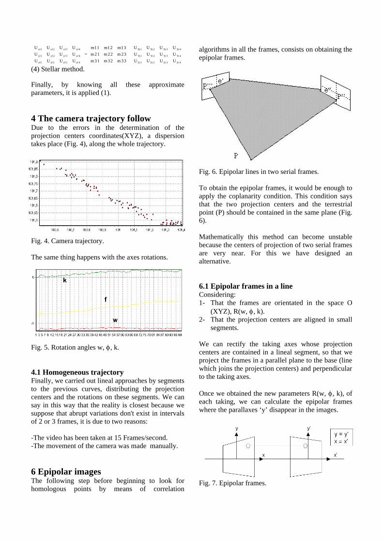
7 Matching points The image matching has two different phases in our work: 1 - A first phase with a small interaction winh the user, where 4 or more control points are selected in the first frame and where it inserts the terrestrial coordinates of these points. The program looks for these points in the other frames and it calculates the first external orientation of the takings (church + stellar + colinearity). 2 - A second phase where the programm finds in the first frame automatically all the points that present some appropriate characteristics to be correlated and located for all the frames. Both in the first phase to determine the size from the appropiate window to each point, like as second phase to find the reliable points to correlate, the program uses an operator that we have denominated operator ‘p-moment'. With this operator we will determine the quality of the point and the size of search window. 7.1 P-moment operator The p-moment operator has been designed considerating theoretical-practical suppossitions: Where: N, is the pixels number of the window. f, is the gray value. µ, is the gray value average of the window Operator functionality: a) To indicate the goodness of a point and their
environment about the possibility of being found accurately in another different frame.
b) To define the size of the appropiated window to correlation.
This operator is applied increasing the size of the window successively thus some graphics are obtained (Fig. 8). This graphics indicates us the size of the good window.
Fig. 8. Operator p-moment graphic.
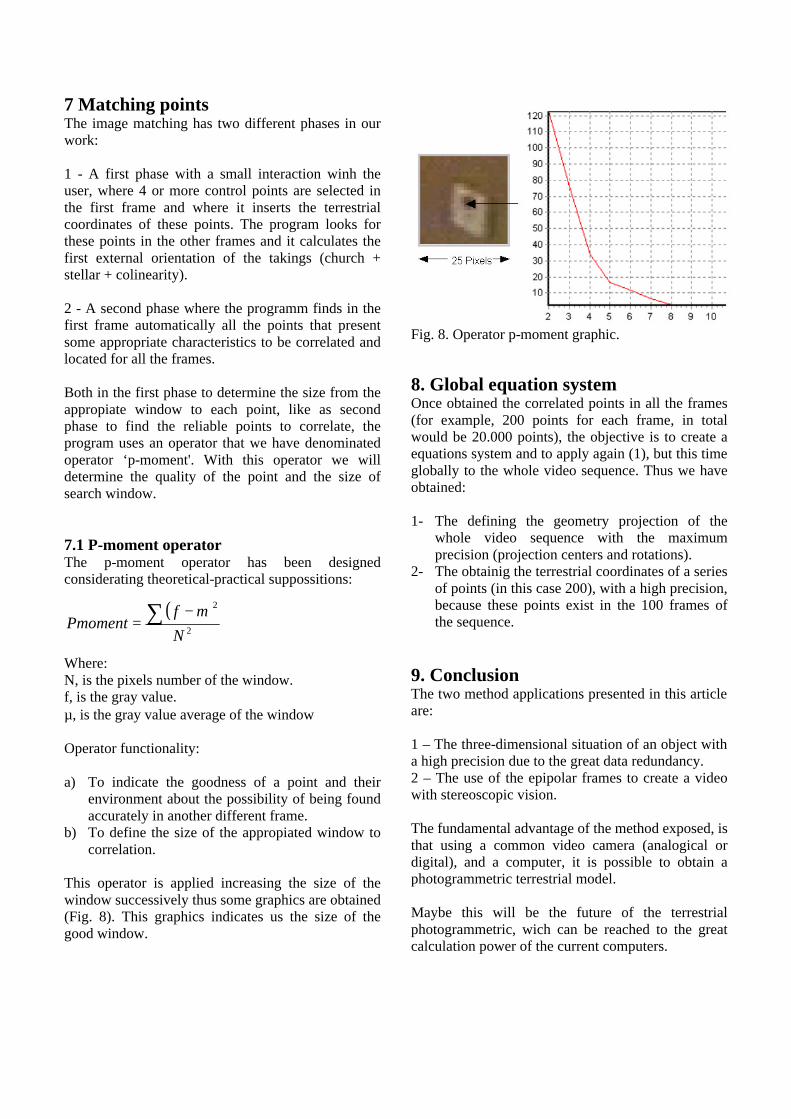
8. Global equation system Once obtained the correlated points in all the frames (for example, 200 points for each frame, in total would be 20.000 points), the objective is to create a equations system and to apply again (1), but this time globally to the whole video sequence. Thus we have obtained: 1- The defining the geometry projection of the
whole video sequence with the maximum precision (projection centers and rotations).
2- The obtainig the terrestrial coordinates of a series of points (in this case 200), with a high precision, because these points exist in the 100 frames of the sequence.
9. Conclusion The two method applications presented in this article are: 1 – The three-dimensional situation of an object with a high precision due to the great data redundancy. 2 – The use of the epipolar frames to create a video with stereoscopic vision. The fundamental advantage of the method exposed, is that using a common video camera (analogical or digital), and a computer, it is possible to obtain a photogrammetric terrestrial model. Maybe this will be the future of the terrestrial photogrammetric, wich can be reached to the great calculation power of the current computers.
( )2
2
N
fPmoment ∑ −
=µ
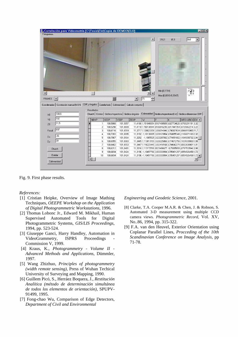
Fig. 9. First phase results. References: [1] Cristian Heipke, Overview of Image Mathing
Techniques, OEEPE Workshop on the Application of Digital Photogrammetric Workstations, 1996.
[2] Thomas Lobonc Jr., Edward M. Mikhail, Human Supervised Automated Tools for Digital Photogrammetric Systems, GIS/LIS Proceedings, 1994, pp. 523-524.
[3] Giuseppe Ganci, Harry Handley, Automation in VideoGrammetry, ISPRS Proceedings - Commission V, 1999.
[4] Kraus, K., Photogrammetry - Volume II - Advanced Methods and Applications, Dümmler, 1997.
[5] Wang Zhizhuo, Principles of photogrammetry (width remote sensing), Press of Wuhan Techical University of Surveying and Mapping, 1990.
[6] Guillem Picó, S., Herráez Boquera, J., Restitución Analítica (método de determinación simultánea de todos los elementos de orientación), SPUPV-91499, 1995.
[7] Fong-chao Wu, Comparison of Edge Detectors, Department of Civil and Environmental
Engineering and Geodetic Science, 2001. [8] Clarke, T.A. Cooper M.A.R. & Chen, J. & Robson, S.
Automated 3-D measurement using multiple CCD camera views. Photogrammetric Record, Vol. XV, No..86, 1994, pp. 315-322.
[9] F.A. van den Heuvel, Exterior Orientation using Coplanar Parallel Lines, Procceding of the 10th Scandinavian Conference on Image Analysis, pp 71-78.