Embed Size (px)
Citation preview
L-3 Integrated Optical Systems- Brashear Proprietary Information
L-3 Communications Corporation, Brashear Division, reserves all rights in connection with this document and in the subject matter represented
herein. The recipient hereby acknowledges these rights and shall not, without permission in writing, disclose or divulge this document in whole or in part to third parties or use it for any purpose other than that for which it was delivered to recipient.
This technical data is controlled under the Export Administration Regulations (EAR) and may not be exported to a Foreign Person, either in the U.S. or abroad, without proper authorization by the U.S. Department of Commerce.
DESTRUCTION NOTICE: Destroy by any method that will prevent disclosure of contents or reconstruction.
615 Epsilon Drive
Pittsburgh, PA 15238
Phone: 412-967-7700, Fax: 412-967-7973 www.L-3Com.com/Brashear
Software Design Document
for the
ATST Top End Optical Assembly
SDD-32506
23 Oct 2012
Approval Name Signature Date
Software Engineer Raymond Balister
Project Engineer Steve Mix
Systems Engineer Sandra Bader
Program Manager Craig Peton
Software Design Document SDD-32506 Rev A
ii L-3 Communications PROPRIETARY
The information contained in this document is subject to the restrictions found on the title page.
DOCUMENT CHANGE RECORD
REVISION ECN DESCRIPTION OF CHANGE DATE CHANGED
BY
APPROVED
BY
Rev - Initial Release
Rev A Changes flowed down from ICD and changes 10/23/12 M. Bock
Software Design Document SDD-32506 Rev A
iii L-3 Communications PROPRIETARY
The information contained in this document is subject to the restrictions found on the title page.
TABLE OF CONTENTS
1. Introduction ...................................................................................... 1
1.1 SCOPE .................................................................................................................. 1
1.2 RELATED DOCUMENTS ..................................................................................... 1
2. System Overview .............................................................................. 2
2.1 INTRODUCTION ................................................................................................... 2
2.2 TEOCS DEPLOYMENT ........................................................................................ 5
2.3 IMPLEMENTATION LANGUAGE ......................................................................... 6
2.4 SOURCE CODE .................................................................................................... 6
2.5 OVERALL USE OF THE ATST COMMON SERVICES ........................................ 7
3. System Context ................................................................................ 8
3.1 CONTEXT DIAGRAM ........................................................................................... 8
3.2 TCS RELATIONSHIP ............................................................................................ 8
3.3 WCCS RELATIONSHIP ........................................................................................ 9
3.4 WFC RELATIONSHIP ........................................................................................... 9
3.5 GIS RELATIONSHIP............................................................................................. 9
4. System Design ................................................................................ 10
4.1 CONFIGURATIONS ............................................................................................ 10
4.2 EVENTS .............................................................................................................. 11
4.3 THE CONTROLLER MODEL ............................................................................. 12
4.4 CONTROLLER LIFECYCLE AND COMMANDS ............................................... 12 4.4.1 LOAD ................................................................................................................... 13
4.4.2 INIT ...................................................................................................................... 13 4.4.3 STARTUP.............................................................................................................. 13 4.4.4 SHUTDOWN .......................................................................................................... 14
4.4.5 UNINIT ................................................................................................................. 14 4.4.6 REMOVE ............................................................................................................... 14 4.4.7 SUBMIT ................................................................................................................ 14
4.4.8 PAUSE ................................................................................................................. 15
4.4.9 RESUME ............................................................................................................... 15 4.4.10 CANCEL/ABORT ................................................................................................... 15 4.4.11 GET ..................................................................................................................... 16 4.4.12 SET ..................................................................................................................... 16
4.5 ATST BASE CONTROLLERS ............................................................................ 16
4.6 ATST BASE TECHNICAL ARCHITECTURE BLOCKS ..................................... 16
Software Design Document SDD-32506 Rev A
iv L-3 Communications PROPRIETARY
The information contained in this document is subject to the restrictions found on the title page.
4.6.1 PROPERTYTAB .................................................................................................... 16 4.6.2 POSTINGTAB ....................................................................................................... 17
4.7 TEOACS CONTROLLERS ................................................................................. 17
4.8 PROPERTIES ..................................................................................................... 18
4.9 DEFAULT STATE ............................................................................................... 19
4.10 HEALTH .............................................................................................................. 19
4.11 ALARMS ............................................................................................................. 20
4.12 LOGGING ........................................................................................................... 20 4.12.1 STATUS MESSAGES .............................................................................................. 20 4.12.2 DEBUG MESSAGES ............................................................................................... 21
4.13 ENGINEERING SCREENS ................................................................................. 21
4.14 CONTROLLING DEVICES THAT TRACK ......................................................... 21 4.14.1 WCCS TRACKING ................................................................................................ 22
4.14.2 WFC TRACKING ................................................................................................... 22
4.15 POSITION FEEDBACK FOR THE TCS .............................................................. 22
4.16 HARDWARE LIMITS .......................................................................................... 23
4.17 FAILURE MODES ............................................................................................... 23 4.17.1 RESPONDING TO INVALID DATA .............................................................................. 23
4.17.2 RESPONDING TO INVALID TRAJECTORY DATA ......................................................... 23 4.17.3 INTERNAL FAILURES ............................................................................................. 24
4.17.4 FAILURES OF TEOA HARDWARE ........................................................................... 24
5. USE CASES ..................................................................................... 25
5.1 TEOA MANAGEMENT CONTROLLER .............................................................. 25 5.1.1 USE CASE: SET TEOA TRACKING MODE ....................................................... 26 5.1.2 USE CASE: SET M2 HEXAPOD CORRECTION SOURCE ............................... 26
5.1.3 USE CASE: SET M2 HEXAPOD POSITION ...................................................... 27 5.1.4 USE CASE: SET M2 FTT POSITION ................................................................. 27
5.1.5 USE CASE: SET LYOT STOP POSITION .......................................................... 28 5.1.6 USE CASE: SEND LOG MESSAGE .................................................................. 28 5.1.7 USE CASE: TEOA MANAGER DETECT GLOBAL INTERLOCK ...................... 28
5.2 M2 HEXAPOD CONTROLLER ........................................................................... 29 5.2.1 USE CASE: RECEIVE AZ/ALT POSITION ........................................................ 29
5.2.2 USE CASE: SEND M2 HEXAPOD CONTROLLER STATUS ............................. 30 5.2.3 USE CASE: SEND M2 HEXAPOD LOG MESSAGE .......................................... 30
5.2.4 USE CASE: RECEIVE M2 HEXAPOD CORRECTIONS .................................... 31 5.2.5 USE CASE: M2 HEXAPOD CONTROLLER DETECT GLOBAL INTERLOCK .. 31
5.3 M2 FAST TIP-TILT CONTROLLER .................................................................... 31 5.3.1 USE CASE: SEND M2 FAST TIP-TILT CONTROLLER STATUS ...................... 32 5.3.2 USE CASE: SEND M2 FAST TIP-TILT LOG MESSAGE ................................... 32
Software Design Document SDD-32506 Rev A
v L-3 Communications PROPRIETARY
The information contained in this document is subject to the restrictions found on the title page.
5.3.3 USE CASE: M2 FAST TIP-TILT DETECT GLOBAL INTERLOCK ..................... 33
5.4 LYOT STOP CONTROLLER .............................................................................. 33 5.4.1 USE CASE: SEND LYOT STOP CONTROLLER STATUS ................................ 34 5.4.2 USE CASE: SEND LYOT STOP LOG MESSAGE ............................................. 34 5.4.3 USE CASE: LYOT STOP DETECT GLOBAL INTERLOCK ............................... 35
5.5 ENGINEERING USE CASES .............................................................................. 35
6. DETAILED DESIGN ......................................................................... 36
6.1 TEOACS TO TEOA COMMUNICATION ............................................................ 36
6.2 INFORMATION IN THE PROPERTY DB ............................................................ 36
6.3 IMPLEMENTING THE COMMUNICATION BETWEEN THE TEOACS AND TEOA HARDWARE CONTROLLERS .......................................................................... 39
6.4 TEOACS JAVA PACKAGES .............................................................................. 40 6.4.1 MANAGEMENT CONTROLLER ATST.TCS.TEOACS ...................................................... 42
6.4.2 SUB-CONTROLLER ATST.TCS.TEOACS.M2POS ......................................................... 43 6.4.3 SUB-CONTROLLER ATST.TCS.TEOACS.M2TT ............................................................ 45 6.4.4 SUB-CONTROLLER ATST.TCS.TEOACS.LYOT ............................................................ 46
7. SEQUENCE DIAGRAMS ................................................................. 48
7.1 SETTING THE TEOA AO MODE ........................................................................ 48
7.2 SENDING TEOA MANAGER STATUS .............................................................. 48
7.3 SETTING M2 HEXAPOD CORRECTION SOURCE ........................................... 49
7.4 SET M2 HEXAPOD POSITION ........................................................................... 49
7.5 SET M2 FTT POSITION ...................................................................................... 50
7.6 SET LYOT STOP POSITION .............................................................................. 51
7.7 SEND TEOA MANAGER LOG MESSAGE ........................................................ 51
7.8 M2 HEXAPOD DETECT GLOBAL INTERLOCK ............................................... 52
7.9 RECEIVE AZ/ALT POSITION ............................................................................. 52
7.10 RECEIVE M2 HEXAPOD CORRECTIONS ......................................................... 53
8. TEOACS JAVA ENGINEERING SCREENS .................................... 54
9. SIMULATION ................................................................................... 59
9.1 TCS SIMULATION REQUIRED BY THE TEOACS ............................................ 59
9.2 GIS SIMULATION REQUIRED BY THE TEOACS ............................................. 59
10. TESTING .......................................................................................... 60
10.1 BUILT-IN TESTS ................................................................................................ 60 10.1.1 M2 HEXAPOD ....................................................................................................... 60
Software Design Document SDD-32506 Rev A
vi L-3 Communications PROPRIETARY
The information contained in this document is subject to the restrictions found on the title page.
10.1.2 M2 FAST TIPTILT .................................................................................................. 60 10.1.3 LYOT STOP .......................................................................................................... 60 10.1.4 TEOA MANAGER ................................................................................................. 60 10.1.5 TESTS EXECUTED AT STARTUP ............................................................................... 60 10.1.6 PLC .................................................................................................................... 60
11. Thermal/Safety PLC ........................................................................ 61
11.1 THERMAL/SAFETY PLC AND FCS INTEGRATION ......................................... 61
11.2 HEAT STOP THERMAL CONTROL ................................................................... 61
11.3 HEAT STOP SHUTTER CONTROL ................................................................... 61 11.3.1 FAULT HANDLING ................................................................................................. 62
11.4 LYOT STOP THERMAL CONTROL ................................................................... 62
11.5 M2 COOLING CONTROL ................................................................................... 62 11.5.1 CHILLER CONTROL ................................................................................................ 63
11.5.2 VARIABLE SPEED BLOWER .................................................................................... 63
12. COMPLIANCE MATRIX ................................................................... 64
Appendix A. Complete UML Design ...................................................................... 72
Appendix A.1. Teoa Manager .................................................................................................................. 72
Appendix A.2. Event Simulation ............................................................................................................. 80
Appendix A.3. Interfaces ......................................................................................................................... 81
Appendix A.4. Lyot Stop .......................................................................................................................... 92
Appendix A.5. M2 Hexapod ................................................................................................................... 100
Appendix A.6. M2 Tip-Tilt ...................................................................................................................... 128
Appendix A.7. Fault System .................................................................................................................. 136
Appendix A.8. Utilites ............................................................................................................................ 139
Software Design Document SDD-32506 Rev A
vii L-3 Communications PROPRIETARY
The information contained in this document is subject to the restrictions found on the title page.
TABLE OF FIGURES
Figure 2.1-1 ATST/TEOA Block Diagram......................................................................................................................... 2 Figure 2.2-1 TEOACS Deployment Diagram ................................................................................................................... 5 Figure 3.1-1 TEOACS Context Diagram .......................................................................................................................... 8 Figure 4.1-1 Configuration States ................................................................................................................................ 11 Figure 4.4-1 ATST CSF Controller Lifecycle .................................................................................................................. 13 Figure 4.7-1 TEOACS Controller Hierarchy .................................................................................................................. 18 Figure 4.14-1 TEOACS AO Mode Transitions ............................................................................................................... 22 Figure 5.1-1 TEOACS Management Controller Use Cases ........................................................................................... 25 Figure 5.2-1 M2 Hexapod Controller Use Cases .......................................................................................................... 29 Figure 5.3-1 M2 Fast Tip-tilt Controller Use Cases ...................................................................................................... 32 Figure 5.4-1 Lyot Stop Use Cases ................................................................................................................................. 34 Figure 6.3-1 TEOACS Namespace Overview ................................................................................................................ 40 Figure 6.4-1 The full TeoaManager class diagam ....................................................................................................... 42 Figure 7.1-1 Sequence diagram for Setting the TEOA Tracking Mode ........................................................................ 48 Figure 7.2-1 Send TEOACS Status ................................................................................................................................ 49 Figure 7.3-1 Set M2 Hexapod Correction Source Sequence Diagram ......................................................................... 49 Figure 7.4-1 Set M2 Hexapod Position Sequence Diagram ......................................................................................... 50 Figure 7.5-1 Set M2 FTT Position Sequence Diagram .................................................................................................. 50 Figure 7.6-1 Set Lyot Stop Position Sequence Diagram ............................................................................................... 51 Figure 7.7-1 Send TEOA Manager Log Message Sequence Diagram ........................................................................... 51 Figure 7.8-1 M2 Hexapod GIS Event Sequence Diagram ............................................................................................. 52 Figure 7.9-1 Receive Az/Alt Position Event .................................................................................................................. 53 Figure 7.10-1 Receive WCCS Correction Sequence Diagram ....................................................................................... 53 Figure 7.10-1 Management Controller JES .................................................................................................................. 55 Figure 7.10-2 M2 Hexapod Controller JES ................................................................................................................... 56 Figure 7.10-3 M2 TT controller JES .............................................................................................................................. 57 Figure 7.10-4 Lyot Stop JES .......................................................................................................................................... 58 Figure 11.3-1 TEOA PLC Heat Stop Shutter Control ..................................................................................................... 62 Figure 11.5-1 M2 Thermal Control Logic ..................................................................................................................... 63 Figure A.1-1 TeoaManager ......................................................................................................................................... 72 Figure A.1-2 TeoaManager_csf ................................................................................................................................... 73 Figure A.1-3 TeoaManager_csfInterfaces ................................................................................................................... 74 Figure A.1-4 TeoaManager_enum .............................................................................................................................. 75 Figure A.1-5 TeoaManager_faults .............................................................................................................................. 76 Figure A.1-6 TeoaManager_inner ............................................................................................................................... 77 Figure A.1-7 TeoaManager_interfaces ....................................................................................................................... 78 Figure A.1-8 TeoaManager_thread............................................................................................................................. 79 Figure A.2-1 EventSim ................................................................................................................................................. 80 Figure A.3-1 IFault ....................................................................................................................................................... 81 Figure A.3-2 IFaultContext .......................................................................................................................................... 82 Figure A.3-3 IFaultTable .............................................................................................................................................. 82 Figure A.3-4 IFttChannel ............................................................................................................................................. 83 Figure A.3-5 IFttConnection ........................................................................................................................................ 84 Figure A.3-6 IHexapod ................................................................................................................................................ 85 Figure A.3-7 IHexapodChannel ................................................................................................................................... 86 Figure A.3-8 IHexapodConnection .............................................................................................................................. 86 Figure A.3-9 IHexapodPos ........................................................................................................................................... 87 Figure A.3-10 ILyotStop .............................................................................................................................................. 87 Figure A.3-11 ILyotStopChannel ................................................................................................................................. 88 Figure A.3-12 ILyotStopConnection ............................................................................................................................ 88
Software Design Document SDD-32506 Rev A
viii L-3 Communications PROPRIETARY
The information contained in this document is subject to the restrictions found on the title page.
Figure A.3-13 IM2tt ..................................................................................................................................................... 89 Figure A.3-14 ISubController ...................................................................................................................................... 89 Figure A.3-15 ITeoaManager ...................................................................................................................................... 90 Figure A.3-16 IThreadContext ..................................................................................................................................... 90 Figure A.3-17 ITMessage............................................................................................................................................. 91 Figure A.4-1 LyotStop ................................................................................................................................................. 92 Figure A.4-2 LyotStop_allCsfInterfaces ....................................................................................................................... 93 Figure A.4-3 LyotStop_connection ............................................................................................................................. 94 Figure A.4-4 LyotStop_connectionOnly ...................................................................................................................... 95 Figure A.4-5 LyotStop_enum ...................................................................................................................................... 95 Figure A.4-6 LyotStop_fault ........................................................................................................................................ 96 Figure A.4-7 LyotStop_interfaces ............................................................................................................................... 97 Figure A.4-8 LyotStop_package .................................................................................................................................. 98 Figure A.4-9 LyotStop_thread ..................................................................................................................................... 99 Figure A.5-1 HexapodLIT ........................................................................................................................................... 100 Figure A.5-2 HexapodLIT_alt1 ................................................................................................................................... 101 Figure A.5-3 HexapodLIT_csf .................................................................................................................................... 102 Figure A.5-4 M2Hexapod+innerClasses .................................................................................................................... 104 Figure A.5-5 M2Hexapod .......................................................................................................................................... 106 Figure A.5-6 M2Hexapod_ext_classes ...................................................................................................................... 108 Figure A.5-7 M2Hexapod_ext_classes2 .................................................................................................................... 108 Figure A.5-8 M2HexConnection ................................................................................................................................ 109 Figure A.5-9 M2HexConnection2 .............................................................................................................................. 111 Figure A.5-10 M2HexConnection_interrupt ............................................................................................................. 111 Figure A.5-11 M2Hex_allCsfInterfaces ..................................................................................................................... 112 Figure A.5-12 M2Hex_all_interfaces_fullInterface ................................................................................................... 114 Figure A.5-13 M2Hex_all_interfaces_partialInterface ............................................................................................. 116 Figure A.5-14 M2Hex_all_interfaces_partialInterface2 ........................................................................................... 118 Figure A.5-15 M2Hex_all_interfaces_partialInterface3 ........................................................................................... 118 Figure A.5-16 M2Hex_and_HexLIT ........................................................................................................................... 119 Figure A.5-17 M2Hex_channelOnly .......................................................................................................................... 119 Figure A.5-18 M2Hex_connectionOnly ..................................................................................................................... 120 Figure A.5-19 M2Hex_connection_channel ............................................................................................................. 121 Figure A.5-20 M2Hex_enum ..................................................................................................................................... 122 Figure A.5-21 M2Hex_fault ....................................................................................................................................... 123 Figure A.5-22 M2Hex_InnerClasses_EventCallbacks ................................................................................................ 124 Figure A.5-23 Inheritance Hierarchy for M2Hexapod class. Both interfaces and classes ........................................ 125 Figure A.5-24 M2Hexapod state thread related classes ........................................................................................... 126 Figure A.5-25 IHexapodPos members of class M2Hexapod ..................................................................................... 127 Figure A.5-26 atst.teoacs.m2pos package and related ............................................................................................. 128 Figure A.6-1 FttConnection_channel ........................................................................................................................ 129 Figure A.6-2 M2TT with inner class and closest extended class ............................................................................... 130 Figure A.6-3 M2TT_allCsf .......................................................................................................................................... 131 Figure A.6-4 M2TT_connection_channel .................................................................................................................. 132 Figure A.6-5 M2TT_enum ......................................................................................................................................... 132 Figure A.6-6 M2TT_ext_classes ................................................................................................................................ 133 Figure A.6-7 M2TT_fault ........................................................................................................................................... 134 Figure A.6-8 M2TT_interfaces .................................................................................................................................. 135 Figure A.7-1 AllFaultRelated ..................................................................................................................................... 136 Figure A.7-2 FaultSetter ............................................................................................................................................ 137 Figure A.7-3 FaultTable ............................................................................................................................................. 137

Software Design Document SDD-32506 Rev A
ix L-3 Communications PROPRIETARY
The information contained in this document is subject to the restrictions found on the title page.
Figure A.7-4 TFault .................................................................................................................................................... 138 Figure A.8-1 Enumerations ....................................................................................................................................... 139 Figure A.8-2 TeoaCallback ........................................................................................................................................ 140 Figure A.8-3 TeoaUtil ................................................................................................................................................ 141 Figure A.8-4 UtilityThread ......................................................................................................................................... 141 Figure A.8-5 Util_enums ........................................................................................................................................... 142
Software Design Document SDD-32506 Rev A
x L-3 Communications PROPRIETARY
The information contained in this document is subject to the restrictions found on the title page.
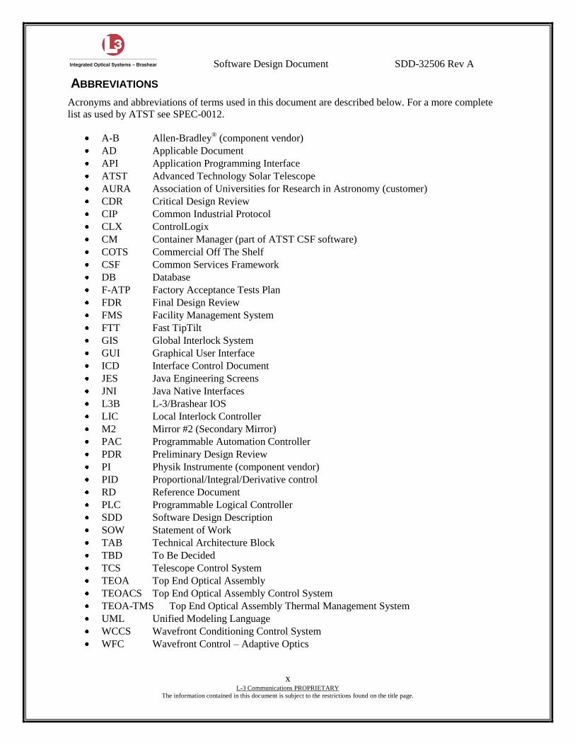
ABBREVIATIONS
Acronyms and abbreviations of terms used in this document are described below. For a more complete
list as used by ATST see SPEC-0012.
A-B Allen-Bradley® (component vendor)
AD Applicable Document
API Application Programming Interface
ATST Advanced Technology Solar Telescope
AURA Association of Universities for Research in Astronomy (customer)
CDR Critical Design Review
CIP Common Industrial Protocol
CLX ControlLogix
CM Container Manager (part of ATST CSF software)
COTS Commercial Off The Shelf
CSF Common Services Framework
DB Database
F-ATP Factory Acceptance Tests Plan
FDR Final Design Review
FMS Facility Management System
FTT Fast TipTilt
GIS Global Interlock System
GUI Graphical User Interface
ICD Interface Control Document
JES Java Engineering Screens
JNI Java Native Interfaces
L3B L-3/Brashear IOS
LIC Local Interlock Controller
M2 Mirror #2 (Secondary Mirror)
PAC Programmable Automation Controller
PDR Preliminary Design Review
PI Physik Instrumente (component vendor)
PID Proportional/Integral/Derivative control
RD Reference Document
PLC Programmable Logical Controller
SDD Software Design Description
SOW Statement of Work
TAB Technical Architecture Block
TBD To Be Decided
TCS Telescope Control System
TEOA Top End Optical Assembly
TEOACS Top End Optical Assembly Control System
TEOA-TMS Top End Optical Assembly Thermal Management System
UML Unified Modeling Language
WCCS Wavefront Conditioning Control System
WFC Wavefront Control – Adaptive Optics
Software Design Document SDD-32506 Rev A
1 L-3 Communications PROPRIETARY
This page is subject to the restrictions on the title page.
1. INTRODUCTION
This is way different This document describes the software design of the ATST Top End Optical
Assembly Control System (TEOACS). The TEOACS acts as the interface and high-level control system
between the Telescope Control System (TCS) and the mechanical systems located at the Top End Optical
Assembly (TEOA).
1.1 SCOPE
The purpose of the TEOACS is to control, on behalf of the TCS, the operation of the top end mechanical
assemblies including position of the secondary mirror (M2) hexapod and tip-tilt to track the sun during
observations. It comprises of all software required to operate the Top End Optical Assembly Thermal
Management System (TEOA-TMS), but does not include hardware or firmware of the TEOA-TMS.
The TEOACS is not responsible for thermal control of the TEOA; this is the responsibility of the Facility
Management System (FMS) and the TEOA-TMS.
During TEOACS development, and in preparation for final delivery, this document will be added to and
updated so that it correctly represents the TEOACS as-built design.
1.2 RELATED DOCUMENTS
SPEC-0001, Science Requirements Document,
SPEC-0005, Software Design Requirements,
SPEC-0012, ATST Glossary and Acronym List,
SPEC-0013, Software Concepts Definition,
SPEC-0019, Telescope Control System Specification,
SPEC-0021, Telescope Control System Design Document,
SPEC-0022, Common Services Framework Reference Manual,
SPEC-0008, Top End Optical Assembly Specification,
TN-0088, Base Software for Control Systems,
TN-0089, Java Engineering Screens User Manual
ICD 1.3-2.1 Top End Optical Assembly to Wavefront Correction Coudé,
ICD 1.3-2.3 Top End Optical Assembly to Wavefront Correction Control System
ICD 1.3-4.4 Top End Optical Assembly to Telescope Control System
Software Design Document SDD-32506 Rev A
2 L-3 Communications PROPRIETARY
This page is subject to the restrictions on the title page.
2. SYSTEM OVERVIEW
2.1 INTRODUCTION
[CUS-1241] [CUS-1264] [CUS-1269] [CUS-1276] [CUS-1279] [CUS-1281] [CUS-1284] [CUS-1286]
[CUS-1287] [CUS-1292] [CUS-1295] [CUS-1297] [CUS-1299] [CUS-1301] [CUS-1305] [CUS-1306]
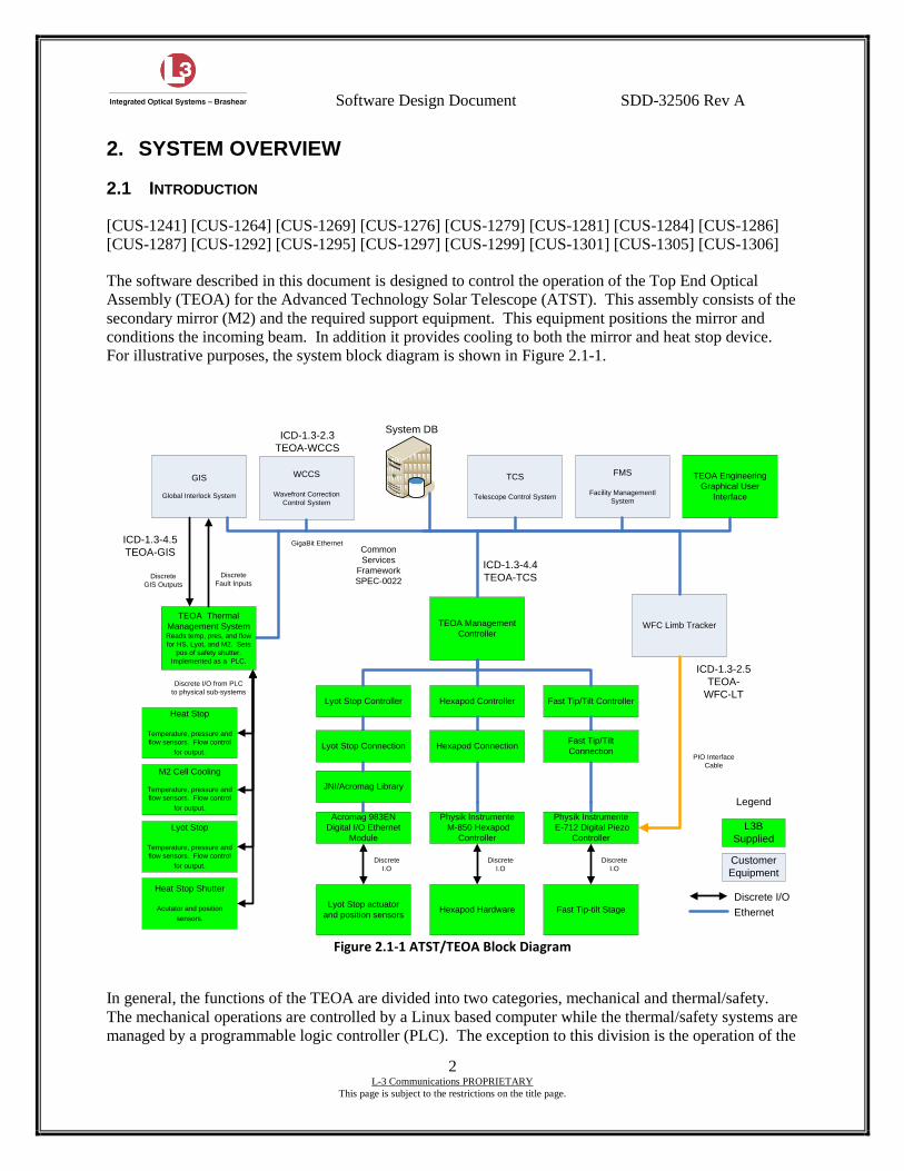
The software described in this document is designed to control the operation of the Top End Optical
Assembly (TEOA) for the Advanced Technology Solar Telescope (ATST). This assembly consists of the
secondary mirror (M2) and the required support equipment. This equipment positions the mirror and
conditions the incoming beam. In addition it provides cooling to both the mirror and heat stop device.
For illustrative purposes, the system block diagram is shown in Figure 2.1-1.
TEOA Management
Controller
Hexapod Controller Fast Tip/Tilt ControllerLyot Stop Controller
Heat Stop Shutter
Acutator and position
sensors.
Physik Instrumente
M-850 Hexapod
Controller
Physik Instrumente
E-712 Digital Piezo
Controller
M2 Cell Cooling
Temperature, pressure and
flow sensors. Flow control
for output.
Lyot Stop actuator
and position sensors
TEOA Thermal
Management System Reads temp, pres, and flow
for HS, Lyot, and M2. Sets
pos of safety shutter.
Implemented as a PLC.
GigaBit Ethernet
Discrete
I.O
WFC Limb Tracker
WCCS
Wavefront Correction
Control System
TCS
Telescope Control System
TEOA Engineering
Graphical User
Interface
Common
Services
Framework
SPEC-0022
FMS
Facility Managementl
System
System DB
PIO Interface
Cable
GIS
Global Interlock System
Lyot Stop
Temperature, pressure and
flow sensors. Flow control
for output.
Heat Stop
Temperature, pressure and
flow sensors. Flow control
for output.
Discrete
GIS Outputs
ICD-1.3-4.5
TEOA-GIS
ICD-1.3-2.3
TEOA-WCCS
ICD-1.3-4.4
TEOA-TCS
ICD-1.3-2.5
TEOA-
WFC-LTDiscrete I/O from PLC
to physical sub-systems
Customer
Equipment
Legend
L3B
Supplied
Discrete I/O
Ethernet
Discrete
Fault Inputs
Acromag 983EN
Digital I/O Ethernet
Module
Hexapod ConnectionFast Tip/Tilt
ConnectionLyot Stop Connection
JNI/Acromag Library
Hexapod Hardware
Discrete
I.O
Fast Tip-tilt Stage
Discrete
I.O
Figure 2.1-1 ATST/TEOA Block Diagram
In general, the functions of the TEOA are divided into two categories, mechanical and thermal/safety.
The mechanical operations are controlled by a Linux based computer while the thermal/safety systems are
managed by a programmable logic controller (PLC). The exception to this division is the operation of the
Software Design Document SDD-32506 Rev A
3 L-3 Communications PROPRIETARY
This page is subject to the restrictions on the title page.
heat stop shutter which is controlled by the PLC. While mechanical in operation, this item is deemed to
be integral to the safety systems. The majority of this document is concerned with the design description
of the TEOACS as it relates to the mechanical positioners.
The TEOACS must respond to positioning demands received from the TCS. These demands control the
absolute positioning of the M2 hexapod and FTT stage. Furthermore, with corrections enabled, the
hexapod position shall track corrections derived from the data received from the Wavefront Condition
Control System (WCCS). These corrections are in the form of delta positions and must be accumulated
and summed with the absolute positions received from the TCS. The FTT stage in addition to responding
to TCS position demands can be put into a state where it will respond directly to high rate absolute
position demands transmitted directly to the FTT control electronics from the Wavefront Control –
Adaptive Optics (WFC) limb tracker. In this mode, the TEOACS is not a participant in the control, but
merely monitors the FTT position.
The TEOACS implements the control for the Lyot stop and positions it according to data received from
the TCS. The position of the Lyot stop is monitored and compared to the requested position and faults
are generated as appropriate.
All command, control, and monitoring functions for the TEOACS are implemented over Ethernet. The
interface protocols to subordinate equipment are implemented in either Java or the native protocols as
implemented by the various vendors of said equipment. The interfaces to the TCS and other telescope
subsystems are implemented using the Common Services Framework (CSF) as developed by Association
of Universities for Research in Astronomy (AURA). This framework consists of an extensive set of
services that provide for health and alarm notifications, logging features, and persistent parameter data
storage. In addition, this framework implements the transport and communications protocol between the
various system components in a near seamless manner. As the TEOACS shall be implemented using CSF
the TEOACS application will be running on a control computer running CentOS 6 Linux and support
packages as specified in SPEC-0022. Furthermore, all communications will be unencrypted. The
TEOACS shall assume that all communications are already secured. It will not implement any firewalls
or other security measures.
In typical operation, all TEOACS communications shall be over Ethernet. This includes communications
with the PI E-710 and M-850 controllers. The TEOACS shall accept hardware configurations from the
TCS and return appropriate responses. In addition, the TEOACS shall transmit, on a regular basis, status,
health and logging information.
The primary role of the TEOACS is to control the hardware present on the TEOA. This hardware
consists of:
M2 Hexapod and PI M-850 hexapod controller
M2 Fast Tip-Tilt stage and PI E-710 Piezoelectric actuator controller
Lyot stop
This hardware is used to accurately and efficiently control the position of the M2 mirror. The Lyot stop is
used as an aperture stop as required during some experiments as defined by SPEC-0001.
Prior to examining the details of the TEOACS software design, it is necessary to gain an understanding of
the overview of the system to be developed and how it relates to the infrastructure required by ATST.
Software Design Document SDD-32506 Rev A
4 L-3 Communications PROPRIETARY
This page is subject to the restrictions on the title page.
The infrastructure, or CSF, contains the base classes from which the TEOACS is constructed. All of the
controllers contained within the TEOACS are derived from one of the base classes contained within this
framework. This framework also includes base classes to support communications and I/O devices. In
accordance with the CSF specification, controllers are contained within containers and are managed by
the Container Manager. The Container Manager is responsible for the deployment and lifecycle
management of the controllers from which the TEOACS is constructed. Another integral part of the
entire system is the DB software toolset which supports the databases. The CSF architecture is dependent
on the DB tools to supply persistent storage for the initial data required by the TEOACS, and for the
purpose of logging several types of messages. From the point of view of the TEOACS, the interfaces to
the databases are encapsulated in classes supplied by the CSF infrastructure and utilized by the TEOACS.
An engineering graphical user interface (GUI) is required for the TEOACS. This engineering GUI is
built on top of the Java Engineering Screens (JES) toolset. The JES toolset is an extension of the CSF
and relies heavily on the classes contained therein. The JES contains tools and classes that facilitate
graphical layout of GUI objects to construct a GUI interface. Behind the interface, it is capable of
communicating, via CSF, to the TEOACS. This enables a user to submit configurations, manage
parameters and exchange events with the TEOACS via a GUI interface for test and diagnostics.
Complete details regarding the JES and related tools can be found in TN-0089.
The Container Manager is used to load, initialize and startup the several controllers implemented in the
TEOACS. Startup of these is accomplished through the CSF and appropriate entries in the application
database. Upon startup, the container manager queries the database and starts up the controllers in
accordance with the returned data. This operation occurs automatically upon boot of the TEOACS
hardware and requires no intervention on the part of the operator.
The TEOACS package, teoacs, comprises four distinct controllers and several other support classes:
TeoaManager is the class implementing the top level management controller atst.tcs.teoacs.
M2Hexapod is the class implementing the hexapod controller atst.tcs.teoacs.m2pos.
M2TT is the class implementing the fast tip-tilt controller atst.tcs.teoacs.mtt.
LyotStop is the class implementing the Lyot stop position controller atst.tcs.teoacs.lyot.
Each of these controllers is based on classes contained within the CSF base class package. Furthermore,
each of the controllers contained within the TEOACS communicates with other controllers via CSF.
Additionally, the TEOACS package contains several other classes used to support communications with
the actual hardware contained in the TEOA as previously enumerated. These classes, through a JNI
interface, support the creation of the communications channel and the actual device driver that
communicates with the hardware. It just prior to the JNI level that the TEOACS control software
implements the simulator. When properly configured, the driver software will refrain from sending
commands to the hardware. Instead it will hold a simulated state for the real hardware and use this to
emulate the actual devices intended to be controlled.
Communications between the TCS and the TEOACS can be classified into two major categories,
configurations and events. Configurations are handled by the top level TEOACS management controller
and typically take the form of attribute value pairs. The configurations are received by the management
controller and automatically routed to the proper lower level controller via code inherited through the
manager controller class. The worker controllers will then attempt to match their state to the received
configuration. Responses to the configuration requests, as well as status and health information are
relayed back to the TCS via events. These events, in addition to being sent to the TCS are also
accumulated by the system database and archived for later reference.
Software Design Document SDD-32506 Rev A
5 L-3 Communications PROPRIETARY
This page is subject to the restrictions on the title page.
For the purpose of fault notification, the GIS communicates with the TEOACS. This communication is in
the form of fault events received via the CSF event service. Should the GIS determine that a fault is
present, it will broadcast that information and it will be received by any controllers which have subscribed
to that event. The TEOACS will be one of those subscribers and will use this event to trigger a transition
to a default, unpowered, non-moving state. In this state, all actuators shall be unpowered.
For the purpose of position adjustments, the WCCS will communicate with the TEOACS. This
communication is in the form of events and contains information necessary for position adjustment of the
M2 hexapod. It consists of delta measurements from the wavefront correction system. These deltas will
be accumulated and used to adjust the demanded hexapod position by simply adding them to the demand
current demand position.
2.2 TEOCS DEPLOYMENT
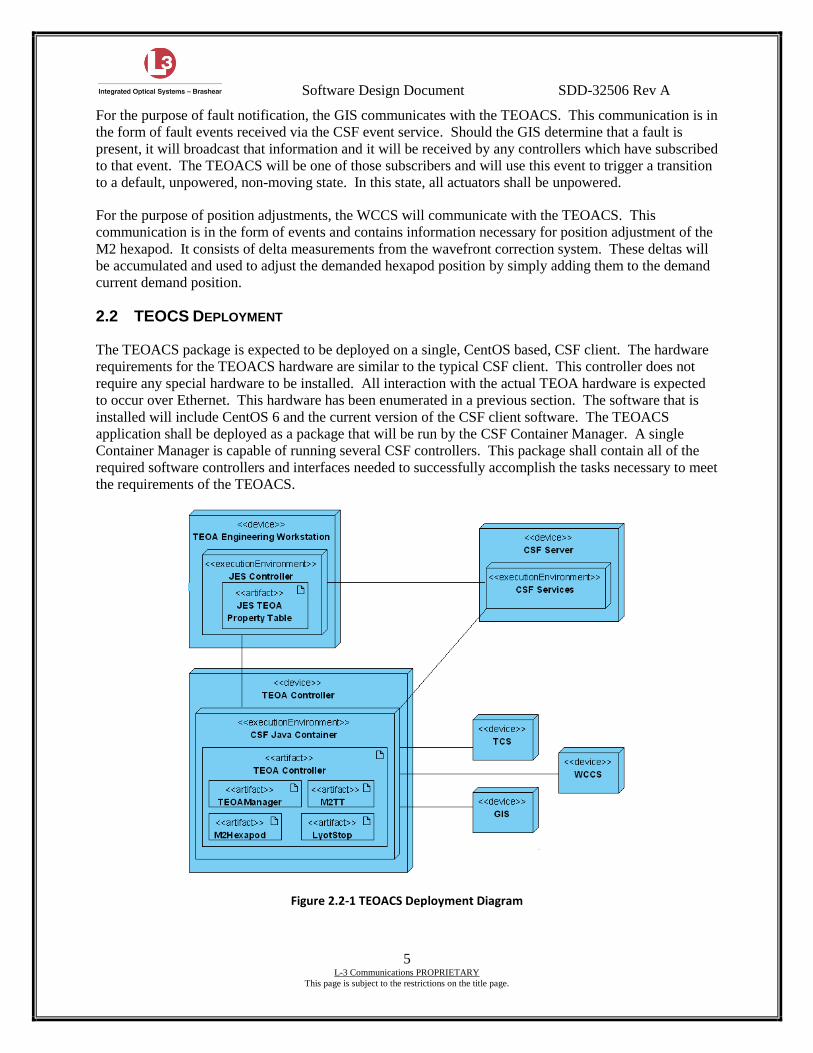
The TEOACS package is expected to be deployed on a single, CentOS based, CSF client. The hardware
requirements for the TEOACS hardware are similar to the typical CSF client. This controller does not
require any special hardware to be installed. All interaction with the actual TEOA hardware is expected
to occur over Ethernet. This hardware has been enumerated in a previous section. The software that is
installed will include CentOS 6 and the current version of the CSF client software. The TEOACS
application shall be deployed as a package that will be run by the CSF Container Manager. A single
Container Manager is capable of running several CSF controllers. This package shall contain all of the
required software controllers and interfaces needed to successfully accomplish the tasks necessary to meet
the requirements of the TEOACS.
Figure 2.2-1 TEOACS Deployment Diagram
Software Design Document SDD-32506 Rev A
6 L-3 Communications PROPRIETARY
This page is subject to the restrictions on the title page.
In the diagram above, the TEOA controller artifact is the package that is running on the TEOA controller
and contains the code needed to control the TEOA. This code is written in Java and conforms to the
requirements of the CSF architecture. There is a requirement to deliver an engineering interface for the
TEOACS. This interface is written using the Java Engineering Screens CSF package and is deployed as a
separate package. The implementation of these screens is expected to be deployed on a separate
computer.
Upon startup of the TEOA controller, the CSF Container Manager will load the TEOACS controllers and
place them in the loaded state. Upon request of the TCS or other subsystems, they will transition to the
init and running states. Only once they have reached the running state will the TEOACS be operational.
Should a critical fault occur at any time, the affected controllers will transition to the default state, turn off
any hardware, and cease any motion. Should it be necessary to shut down the TEOACS, the controllers
may be commanded to uninit and to unload. This will shut down the TEOA hardware, place them in a
default state, and release all allocated resources.
2.3 IMPLEMENTATION LANGUAGE
[CUS-1246] [CUS-1247]
All TEOACS controllers/components and associated software are implemented in Java. However, the
library selected to provide communication with the Physik Instrumente (PI) controllers is written in C,
calls to this library will be made from Java using Java Native Interface (JNI) C code. The C code will
provide a wrapper enabling calls and return of data to and from the PI C communications library in Java.
Prior to use, all libraries shall be submitted to AURA for approval before they are used to implement the
functionality of the TEOACS.
Java is used as the language of choice as previous prototyping carried out using Java containers and
controllers has demonstrated there is no compelling reason to write CSF applications in C++. In fact
some of the base classes (including specialized management controllers) will only be supported in Java,
and it is therefore desirable to use Java in the TEOACS controllers to utilize the functionality already
provided.
2.4 SOURCE CODE
[CUS-1246]
All source code used by and implemented as part of the TEOACS contract will be provided. As the code
is developed it will be committed to a code source repository (Perforce) at the Contractor’s location. At
the various TEOACS delivery stages the code constituting the delivery shall be tagged (labeled) in the
repository and delivered to ATST. The code then can be extracted, inserted into the ATST code
repository, and reviewed. All implemented source code shall be documented in a manner consistent with
good software practices, using tools such as Javadoc and doxygen.
All implemented source files shall contain a header including the author(s), and functional description.
All functions within a source file shall have a description of the interface and operation of the function,
and shall be clearly commented.
All third-party software will be delivered as part of the regular release cycle. Third-party software will be
approved by ATST before its inclusion in the design and construction.
Software Design Document SDD-32506 Rev A
7 L-3 Communications PROPRIETARY
This page is subject to the restrictions on the title page.
2.5 OVERALL USE OF THE ATST COMMON SERVICES
[CUS-1246]
The TEOACS, as one of the systems of the ATST, must work seamlessly with the other systems that
make up the overall ATST control system. In particular it must accept and act on configurations sent by
the TCS. To accomplish this, the TEOACS is built using the ATST CSF, which in turn constrains its
design.
At the highest level the TEOACS will consist of a collection of CSF Java class files. The TEOACS
container will hold a number of controllers that will be initialized and started by the container manager
via the init and startup command methods. During this phase the TEOACS controllers will attempt to
make connections to the other ATST components with which they need to communicate and will retrieve
their initial state from the runtime database through the use of the property service.
The workers of the system will be implemented as ATST controllers (deriving from
atst.base.HardwareController) providing the command/action/response behavior needed to handle the
submission of configurations. Details of the controller model in general and the particular controllers and
components that will be derived by the TEOACS can be found in the CSF User Manual (SPEC-0022-1)
and Base Software for Control Systems (TN-0088).
Software Design Document SDD-32506 Rev A
8 L-3 Communications PROPRIETARY
This page is subject to the restrictions on the title page.
3. SYSTEM CONTEXT
This section describes the context of the TEOACS with respect to other systems of the ATST with which
it must communicate. Successive sections describe what functions the TEOACS must perform; however
the details of these functions are discussed in later sections.
The TEOACS context is bounded above it by the TCS and the WCCS and below it by the actual TEOA
hardware. The TEOACS receives configurations from the TCS and correction event data from the
WCCS. The TEOACS also receives information from the GIS with regards to observatory wide interlock
conditions and safety events.
3.1 CONTEXT DIAGRAM
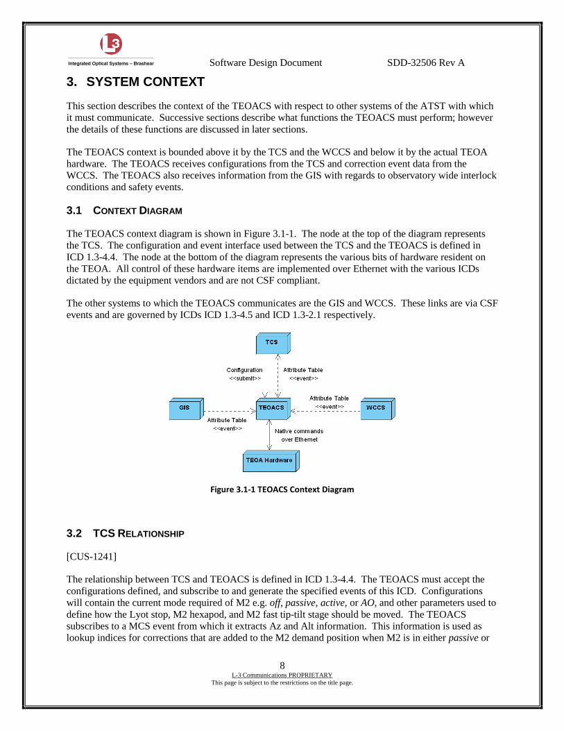
The TEOACS context diagram is shown in Figure 3.1-1. The node at the top of the diagram represents
the TCS. The configuration and event interface used between the TCS and the TEOACS is defined in
ICD 1.3-4.4. The node at the bottom of the diagram represents the various bits of hardware resident on
the TEOA. All control of these hardware items are implemented over Ethernet with the various ICDs
dictated by the equipment vendors and are not CSF compliant.
The other systems to which the TEOACS communicates are the GIS and WCCS. These links are via CSF
events and are governed by ICDs ICD 1.3-4.5 and ICD 1.3-2.1 respectively.
Figure 3.1-1 TEOACS Context Diagram
3.2 TCS RELATIONSHIP
[CUS-1241]
The relationship between TCS and TEOACS is defined in ICD 1.3-4.4. The TEOACS must accept the
configurations defined, and subscribe to and generate the specified events of this ICD. Configurations
will contain the current mode required of M2 e.g. off, passive, active, or AO, and other parameters used to
define how the Lyot stop, M2 hexapod, and M2 fast tip-tilt stage should be moved. The TEOACS
subscribes to a MCS event from which it extracts Az and Alt information. This information is used as
lookup indices for corrections that are added to the M2 demand position when M2 is in either passive or
Software Design Document SDD-32506 Rev A
9 L-3 Communications PROPRIETARY
This page is subject to the restrictions on the title page.
active modes. When in AO mode, these corrections are not used as the WFC limb tracker is directly
controlling the M2 fast tip-tilt stage.
The current status of the M2 is broadcast on the events atst.tcs.teoacs.cStatus,
atst.tcs.teoacs.m2pos.cStatus, atst.tcs.teoacs.m2tt.cStatus, and atst.tcs.teoacs.lyot.cStatus. These
events and their frequencies are described in greater detail in ICD 1.3-4.4. The TCS or any other
interested systems may subscribe to these events.
3.3 WCCS RELATIONSHIP
When the TEOACS is in passive mode, the M2 hexapod is getting position data from the TCS and error
correction data from lookup tables. When in active mode, the hexapod gets additional data from the
WCCS. This data is received in the form of events and contains delta correction information as defined
by ICD 1.3-2.3. This data must be accumulated by the TEOACS and added to the demand position
received from the TCS. This WCCS event is generated at the rate of 1 Hz. This data is used to make
corrections to the M2 hexapod position when the M2 is in an active mode.
3.4 WFC RELATIONSHIP
Although there is no direct relationship between the WFC and the TEOACS, there is nonetheless a
connection between the WFC and the TEOA M2 fast tip-tilt controller. When the TEOACS is in the AO
mode the TEOACS no longer controls the position of the M2 fast tip-tilt stage. Instead, the FTT stage is
controlled directly by the WFC system via a direct digital connection. The TEOACS is still able to
monitor the FTT position and continues to report the cStatus events. The TEOACS still maintains the
ability to control the source of position data through the Ethernet interface to the M2 FTT controller.
3.5 GIS RELATIONSHIP
[CUS-1306]
At all times the TEOACS monitors events from the GIS as specified by ICD 1.3-4.5. Should the GIS
alert the TEOACS of a fault condition, the TEOACS will respond by entering a default state. In this
state, the actuators will be in a safe, unpowered state. The TEOACS shall remain in the default state until
it is notified by the GIS that the fault has been cleared. At no time will the TEOACS be required to
participate in safety critical operation. Ensuring the safety of the equipment and/or personnel is the sole
responsibility of the GIS. The TEOACS shall only react so far as has been indicated within the
specification requirements.
Software Design Document SDD-32506 Rev A
10 L-3 Communications PROPRIETARY
This page is subject to the restrictions on the title page.
4. SYSTEM DESIGN
This section describes the system design of the TEOACS and in particular its use of the ATST CSF. The
TEOACS design is constrained by the need to interact seamlessly with the rest of the ATST systems and
to use the CSF in its operations. The first subsections of this section therefore recap and summarize the
CSF design with regard to the use of configurations, and in particular the controller model. Subsection 4.7
then describes the controller model as applied to the TEOACS. Subsequent subsections then describe
other operations of the TEOACS that rely heavily on the CSF.
4.1 CONFIGURATIONS
Configurations lie at the heart of the ATST CSF. Configurations consist of a list of attributes and values
that the system receiving the configuration must match. CSF controllers do the matching of the
configuration’s attributes to the system’s attributes. The internal configuration of a controller can be set
up by issuing a series of set commands (section 4.4.12) or more usually by sending a complete
configuration with a submit command (section 4.4.7).
A configuration is a specialized form of an AttributeTable class that also contains a unique configuration
ID and header tag. An AttributeTable consists of a collection of Attribute objects each of which has a
name and value. Internally an Attribute value is stored as a string representation of the actual value, and
so multiple attributes of different types can be stored in the same AttributeTable.
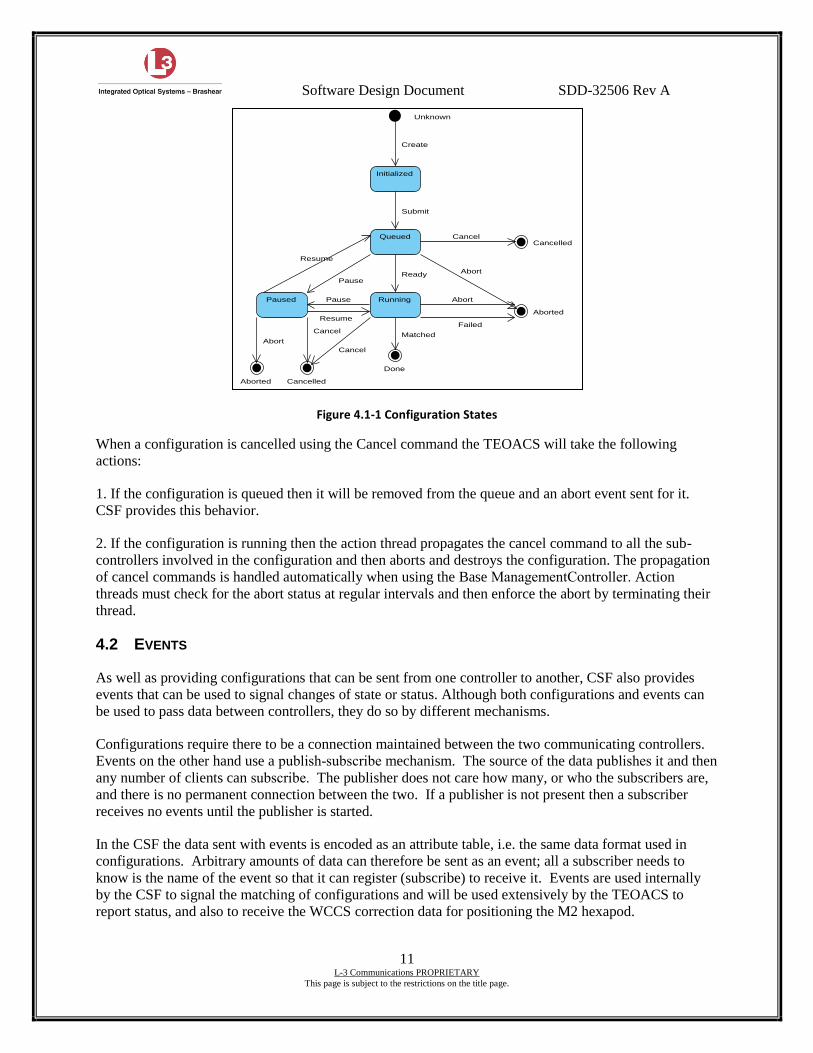
Configurations go through a set of states during their lifecycle as illustrated in Figure 4. The controller
depending sets the state on which command the controller receives relating to the configuration. The
controller also sets the state when the action relating to the configuration completes (either successfully or
unsuccessfully). The commands are Submit, Cancel, Pause, Resume and Abort. The completion
possibilities are Done, Cancelled or Aborted.
A configuration is submitted to a controller using the submit() method. The controller then performs a
quick check of the attributes in the configuration to make sure the attributes are valid. The controller then
passes the attributes to the doSubmit() method to make sure that the combination of attributes make a
valid configuration. If the attributes do make a valid configuration the configuration is scheduled, and the
submit method returns OK. The acceptance or rejection of a command shall occur within 0.1 seconds. If
the configuration is not valid the submit method returns with a problem code. When the configuration’s
action starting time is reached (the default is for immediate execution) then the doCanRun() method is
called, providing a hook for final checking that the configuration can be executed at the current time. If
the doCanRun() method returns true then the doSerialAction() method is called followed by the starting
of an action thread. The action thread calls the doAction() method that does the required work to match
the component attributes to those of the configuration. Once the work is completed the method and action
thread complete. Three events are usually generated for a configuration action:
An event is generated when the actions is scheduled.
Another event is generated when the action is started.
A final event is generated when the action completes.
Configurations can be Cancelled/Aborted, which will lead to additional events being generated.
Software Design Document SDD-32506 Rev A
11 L-3 Communications PROPRIETARY
This page is subject to the restrictions on the title page.
Figure 4.1-1 Configuration States
When a configuration is cancelled using the Cancel command the TEOACS will take the following
actions:
1. If the configuration is queued then it will be removed from the queue and an abort event sent for it.
CSF provides this behavior.
2. If the configuration is running then the action thread propagates the cancel command to all the sub-
controllers involved in the configuration and then aborts and destroys the configuration. The propagation
of cancel commands is handled automatically when using the Base ManagementController. Action
threads must check for the abort status at regular intervals and then enforce the abort by terminating their
thread.
4.2 EVENTS
As well as providing configurations that can be sent from one controller to another, CSF also provides
events that can be used to signal changes of state or status. Although both configurations and events can
be used to pass data between controllers, they do so by different mechanisms.
Configurations require there to be a connection maintained between the two communicating controllers.
Events on the other hand use a publish-subscribe mechanism. The source of the data publishes it and then
any number of clients can subscribe. The publisher does not care how many, or who the subscribers are,
and there is no permanent connection between the two. If a publisher is not present then a subscriber
receives no events until the publisher is started.
In the CSF the data sent with events is encoded as an attribute table, i.e. the same data format used in
configurations. Arbitrary amounts of data can therefore be sent as an event; all a subscriber needs to
know is the name of the event so that it can register (subscribe) to receive it. Events are used internally
by the CSF to signal the matching of configurations and will be used extensively by the TEOACS to
report status, and also to receive the WCCS correction data for positioning the M2 hexapod.
Aborted Cancelled
Done
Paused
Aborted
Cancelled
Running
Queued
Initialized
Unknown
Cancel
Resume
Resume
Pause
Pause
Cancel
AbortMatched
Abort
Failed
Cancel
AbortReady
Submit
Create
Software Design Document SDD-32506 Rev A
12 L-3 Communications PROPRIETARY
This page is subject to the restrictions on the title page.
To ensure the status of TEOACS items that change in a non-periodic or low frequency fashion are readily
available to other systems as events, these items, e.g. position of the Lyot stop, will be published by
controllers at 1Hz in a cStatus event. Every TEOACS controller will publish a cStatus event containing
its current status. The contents (attributes) of the cStatus event of each controller are defined in the TCS
to TEOACS ICD (ICD-1.3/4.4).
4.3 THE CONTROLLER MODEL
[CUS-1257]
An ATST CSF Controller implements what is called the command/action/response model. In this model
commands are separated from the actions they trigger. In this way many commands may be sent to a
controller resulting in many simultaneous actions, and in particular a controller is not blocked whilst
waiting for a previous command/action to complete. In the CSF commands are passed to controllers as
configurations; the configuration’s attributes describe the command in the form of values that must be
matched by the controller for the command to complete.
On receipt of a configuration describing the command’s values, the controller will send an immediate
response to the sender saying whether the attributes sent with the configuration are accepted or rejected
(within 0.1 seconds). It will then queue the configuration for either immediate or later action. Once
queued, the controller is ready to accept another command contained in another configuration. Separate
threads under the control of an action manager handle the actions started by configurations. Configuration
actions can complete as either Done, Cancelled or Aborted. Normal completion for a configuration action
is Done, but if an error occurs then it will be Aborted. This response is advertised by the posting of a
configuration action status event, which is automatically monitored by the CSF. Controllers can attach a
callback to perform processing on receipt of the action’s status event, if no further processing is required
the callback can be null. The action status event’s name is prefixed with the name of the controller
posting the event, as is the name of the attribute containing the event’s status value. The event name is
made up of this prefix and the text status. For example, if the controller atst.tcs.teoacs posts an action
status event, the name of this event is atst.tcs.teoacs.cStatus and this matches the name of the action status
attribute containing the event’s value.
Controllers accept a configuration as a parameter in the submit command. It is important for the
TEOACS to distinguish between the completion of an action and the state of an underlying piece of
hardware. A CSF configuration action is in the Running state until it is Done, Cancelled or Aborted.
This may or may not coincide with an underlying piece of hardware being physically stationary or not.
For example, if the Lyot stop is moved from the closed to open position, when the hardware reaches the
open position a signal must be sent to the action thread to tell the configuration it is Done. In this case the
hardware device stopping coincides with the configuration being Done. However, in the case of slewing
the mount, the action is Done when the mount first matches the position and velocity tolerances. The
mount will continue to track (move) and it would be incorrect to consider the configuration as still
Running because of this. Instead the configuration is considered Done when the mount is moving within
specified tolerance.
4.4 CONTROLLER LIFECYCLE AND COMMANDS
[CUS-1246] [CUS-1251]
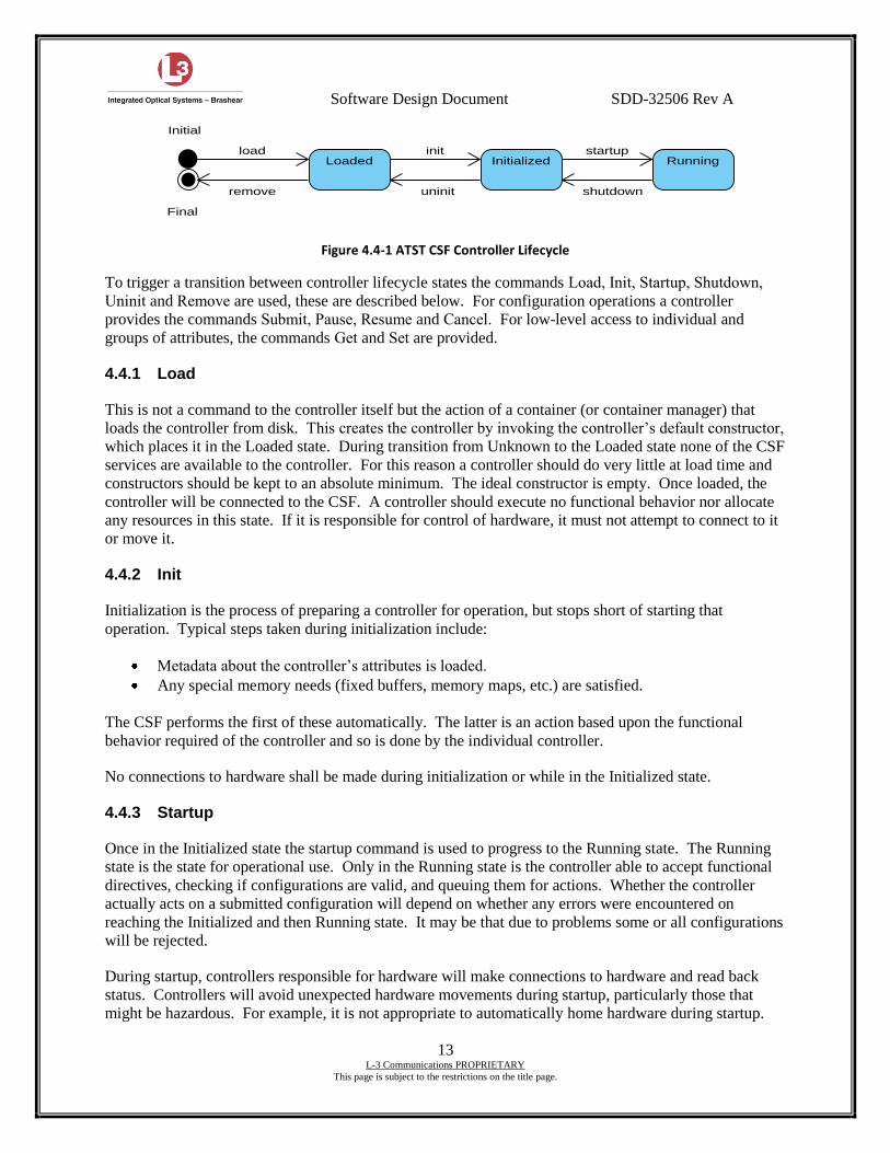
During processing an ATST CSF controller moves through a well-defined lifecycle, as illustrated in
Figure 4.4-1.
Software Design Document SDD-32506 Rev A
13 L-3 Communications PROPRIETARY
This page is subject to the restrictions on the title page.
Figure 4.4-1 ATST CSF Controller Lifecycle
To trigger a transition between controller lifecycle states the commands Load, Init, Startup, Shutdown,
Uninit and Remove are used, these are described below. For configuration operations a controller
provides the commands Submit, Pause, Resume and Cancel. For low-level access to individual and
groups of attributes, the commands Get and Set are provided.
4.4.1 Load
This is not a command to the controller itself but the action of a container (or container manager) that
loads the controller from disk. This creates the controller by invoking the controller’s default constructor,
which places it in the Loaded state. During transition from Unknown to the Loaded state none of the CSF
services are available to the controller. For this reason a controller should do very little at load time and
constructors should be kept to an absolute minimum. The ideal constructor is empty. Once loaded, the
controller will be connected to the CSF. A controller should execute no functional behavior nor allocate
any resources in this state. If it is responsible for control of hardware, it must not attempt to connect to it
or move it.
4.4.2 Init
Initialization is the process of preparing a controller for operation, but stops short of starting that
operation. Typical steps taken during initialization include:
Metadata about the controller’s attributes is loaded.
Any special memory needs (fixed buffers, memory maps, etc.) are satisfied.
The CSF performs the first of these automatically. The latter is an action based upon the functional
behavior required of the controller and so is done by the individual controller.
No connections to hardware shall be made during initialization or while in the Initialized state.
4.4.3 Startup
Once in the Initialized state the startup command is used to progress to the Running state. The Running
state is the state for operational use. Only in the Running state is the controller able to accept functional
directives, checking if configurations are valid, and queuing them for actions. Whether the controller
actually acts on a submitted configuration will depend on whether any errors were encountered on
reaching the Initialized and then Running state. It may be that due to problems some or all configurations
will be rejected.
During startup, controllers responsible for hardware will make connections to hardware and read back
status. Controllers will avoid unexpected hardware movements during startup, particularly those that
might be hazardous. For example, it is not appropriate to automatically home hardware during startup.
Final
RunningInitializedLoaded
Initial
remove uninit shutdown
startupinitload
Software Design Document SDD-32506 Rev A
14 L-3 Communications PROPRIETARY
This page is subject to the restrictions on the title page.
Reaching the Running state is a necessary condition for a controller to be operational but for some
controllers it may not be fully sufficient. For example, a controller responsible for a tracking mechanism
will not begin tracking operations until specifically told to do so by the submission of a configuration.
4.4.4 Shutdown
Shutdown is essentially the reverse process of startup so any actions undertaken as part of startup should
be undone during the processing of the shutdown command, e.g., close hardware connections. Once
shutdown has completed the component state will return to the Initialized state and its capabilities must
reflect this. While in the Running state the controller may have executed many configurations that leave
mechanisms active, these shall be halted as part of the shutdown. For example if the azimuth carousel is
tracking it shall be stopped, motors powered down, and brakes applied.
Besides restarting the component, using the startup command, the only other operation available on an
Initialized component is the un-initialization of the component using the uninit command.
4.4.5 Uninit
This command is the reverse of init and will undo any actions that resulted from init command
processing. As a result of the uninit command the controller will return back to the Loaded state as if it
had just been loaded from disk.
4.4.6 Remove
As with the load command, the remove command is not a command to the controller itself but rather an
action of the container (or container manager). The action of remove is to remove the controller’s
instance from memory.
4.4.7 Submit
Once a controller is in the Running state it is ready to act on any configurations sent to it. Configurations
are sent using the submit command. On receipt of a submit command the controller will verify that the
configuration is valid. Once the verification is complete, the command thread queues the configuration
and signals the action manager. At this point a response is returned to the external source of the
command. The response is an integer representing the result of the submission; its value will be one of
the following:
OK (0) – The configuration has been accepted for action. This is the only code that will result in
the configuration being scheduled for action.
BUSY (-1) – The configuration has been rejected because the controller cannot perform any
additional simultaneous actions and cannot queue the submitted configuration.
BAD_PARAM (-2) – The configuration has an invalid parameter value.
MISSING_PARAM (-3) – The configuration is missing a parameter value that is required.
INCONSISTENT_PARAM (-4) – A parameter of the configuration is inconsistent with the other
parameters submitted in the configuration.
EXCEPTION (-5) – There is a runtime error in the submit code for the target controller.
NOT_RUNNING (-6) – The target controller is not in the Running state.
DUPLICATE (-7) – The configuration ID matches one already being acted upon.
NO_CONFIG (-8) – There was no configuration submitted.
Software Design Document SDD-32506 Rev A
15 L-3 Communications PROPRIETARY
This page is subject to the restrictions on the title page.
SIMULATED (-9) – The request came from a component running in simulation mode.
Within the TEOACS, validation will consist of a number of stages:
The name of the attribute will be checked to ensure it is a valid attribute name. If any attribute
name is not a valid TEOACS attribute name then the configuration will be rejected with return
value BAD_PARAM. The alternative of simply ignoring invalid attribute names could lead to a
situation where a complex configuration is submitted with one of the attribute names spelt
incorrectly. The user might not notice that the configuration had been accepted but with one
attribute discarded in the process.
The value of the attribute will be range checked. Range checking is provided through the CSF
(property database) and is done by the CSF submit() method (see 4.1). If the value is out of
range then the whole configuration is rejected with the return value BAD_PARAM.
Conflict checking. This is a check that the configuration as sent contains no conflicting demands
and is done in the component’s doSubmit() method (see 4.1). For example setting the
hexapod power to off and also setting the position would conflict as the hexapod would
simultaneously be asked to move and to power it off. The configuration is rejected with return
value INCONSISTENT_PARAM.
If all validation checks are passed then the configuration is handed to an action thread for execution and
the OK value is returned from the submit command.
4.4.8 Pause
This command pauses the actions associated with an earlier submit command. During action processing
the action thread will check for the arrival of a pause command and if feasible, in the restraints of possible
hardware operations, the action will be paused. The action will be resumed on receipt of a resume
command.
The TEOACS does not accept Pause.
4.4.9 Resume
The resume command restarts actions previously paused using the pause command. The action thread
associated with the paused action will recommence its processing at the stage reached prior to arrival of
the pause command.
The TEOACS does not accept Resume.
4.4.10 Cancel/Abort
The cancel/abort command will remove a configuration from the queue if it has not yet been started. If the
configuration is already active then an abort signal is sent to the action thread and the configuration is
destroyed.
The actual operation carried out when a cancel command is received will depend upon the abilities
provided to stop ongoing hardware operations.
Software Design Document SDD-32506 Rev A
16 L-3 Communications PROPRIETARY
This page is subject to the restrictions on the title page.
4.4.11 Get
This is a low-level command that can be issued to a controller once the controller is in the Initialized
state; it does not have to be Running for this command to be accepted. The get command can be used to
fetch the value of any attributes from the current internal configuration of the controller. If a get is called
without any specified attributes then the values of all attributes will be returned.
4.4.12 Set
This is a low-level command that can be issued to a controller once the controller is in the Initialized
state; it does not have to be Running for this command to be accepted. The set command can be used to
set the value of any attributes of the current internal configuration of the controller. These values will be
overridden if they are subsequently specified in a configuration that is submitted to the controller for
execution using the submit command.
4.5 ATST BASE CONTROLLERS
[CUS-1247]
The ATST application base is a suite of software that extends the ATST CSF beyond the technical
architecture. The application base includes controllers that provide generally useful functional behavior
that is not specific to a particular ATST system. Details of controllers contained in base can be found in.
TEOACS controllers are implemented by extending the following base controllers:
atst.base.management.action.ManagementController
atst.base.hardware.HardwareComponent
atst.base.hardware.HardwareController
atst.base.hardware.motion.MotionController
4.6 ATST BASE TECHNICAL ARCHITECTURE BLOCKS
Technical Architecture Blocks (TABs) are used to add technical code to a controller. A large portion of
the code in many of a controller’s methods is bookkeeping and error checking that needs to be done regardless of other operations. TABs are standalone objects that have some close relation to a controller
and are constructed in the controller’s namespace, i.e. TABs belonging to one controller cannot interfere
or corrupt another controller’s TABs.
The purpose of TABs is to remove the necessity to duplicate code that duplicates operations across
different controllers. The only duplicated code is registering the TAB with the superclass. Since TABs
are standalone and are iterated through, there is no fear of overriding methods from a superclass and
forgetting to call the superclass’s method. Since TABs are standalone objects they can be mixed and
matched as needed and there are no issues with multiple inheritances. Since each TAB only has to do one
thing it makes it easier to track down bugs, and modify behavior; bug fixes and modifications are made
once in the TAB not in every component using the TAB.
4.6.1 PropertyTAB
The PropertyTAB allows get and set calls to a controller to query or set the controller’s property
metadata. Every time that a controller’s get method is called the controller will iterate through a list of all
Software Design Document SDD-32506 Rev A
17 L-3 Communications PROPRIETARY
This page is subject to the restrictions on the title page.
TABs that implement get()and call each of their get methods. In the case of the PropertyTAB, its get
method will look for queries of property metadata and fill in the appropriate values in the attribute table.
The PropertyTAB is automatically added to all controllers and so every TEOACS controller will contain
this functionality.
4.6.2 PostingTAB
The PostingTAB continually posts information from a controller that implements the IPoster interface. It
is configured using properties to setup its event channel name and posting rate. It can also be enabled and
disabled. This TAB simplifies the posting of regular attribute tables from controllers by taking care of
setting up the task, managing the timing of the task and ensuring it is created at init, started at startup,
stopped at shutdown and destroyed at uninit. Each TEOACS controller will use a PostingTAB to post its
cStatus event, and if applicable, its cPos event.
4.7 TEOACS CONTROLLERS
[CUS-1246]
The ATST controller model imposes a strict hierarchy on the control flow through the ATST control
system. This means that any attribute destined for a sub-controller must pass through a parent. This
means that attributes map directly on to the controller hierarchy. For example, the attribute
atst.tcs.teoacs.m2pos.aoMode may be sent from the TCS to the top-level TEOACS MangementController
atst.tcs.teoacs, which in turn will forward the attribute to the atst.tcs.teoacs.m2pos sub-controller. This
will be handled automatically as the top-level TEOACS MangementController is implemented as an
extension of the CSF base ManagementController class that provides this functionality.
A controller in the hierarchy may intercept an attribute and as a result generate its own configuration.
This will occur in the top-level TEOACS ManagementController, allowing multiple subsystem mode
changes by issuing just a few (or maybe one) attribute tables. An example of this would be the
atst.tcs.teoacs.mode attribute; when the top-level TEOA controller receives this attribute in a
configuration it will generate new configurations containing mode attributes for its subordinate
controllers, e.g. atst.tcs.teoacs.m2pos.mode and atst.tcs.teoacs.m2tt.mode. Whenever new configurations
are generated they are done so using the original configuration as a starting point. This ensures the
configuration ID is preserved (appended to) and consequently all configurations can be traced from the
originating configuration.
The TEOACS controller hierarchy is shown in Figure 4.7-1. This shows that all configurations flow
through the atst.tcs.teoacs ManagementController. The hierarchy and names used to identify the
controllers are defined in the TCS to TEOA ICD 1.3-4.4.
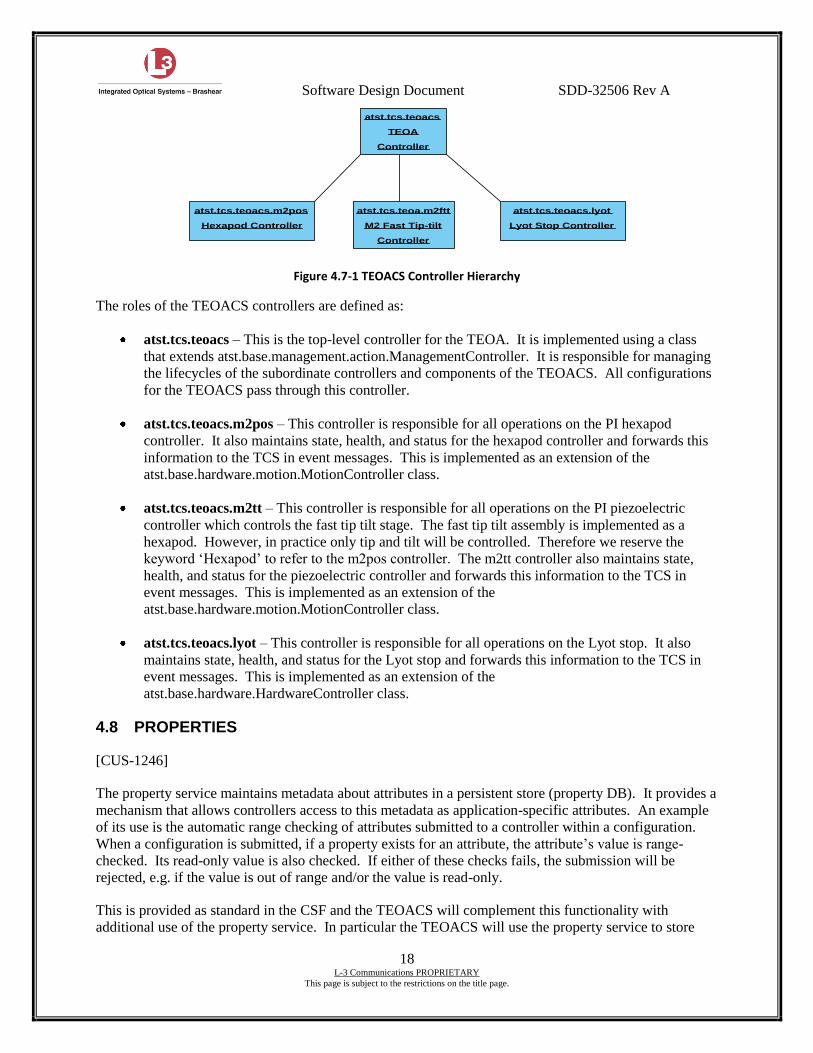
Software Design Document SDD-32506 Rev A
18 L-3 Communications PROPRIETARY
This page is subject to the restrictions on the title page.
Figure 4.7-1 TEOACS Controller Hierarchy
The roles of the TEOACS controllers are defined as:
atst.tcs.teoacs – This is the top-level controller for the TEOA. It is implemented using a class
that extends atst.base.management.action.ManagementController. It is responsible for managing
the lifecycles of the subordinate controllers and components of the TEOACS. All configurations
for the TEOACS pass through this controller.
atst.tcs.teoacs.m2pos – This controller is responsible for all operations on the PI hexapod
controller. It also maintains state, health, and status for the hexapod controller and forwards this
information to the TCS in event messages. This is implemented as an extension of the
atst.base.hardware.motion.MotionController class.
atst.tcs.teoacs.m2tt – This controller is responsible for all operations on the PI piezoelectric
controller which controls the fast tip tilt stage. The fast tip tilt assembly is implemented as a
hexapod. However, in practice only tip and tilt will be controlled. Therefore we reserve the
keyword ‘Hexapod’ to refer to the m2pos controller. The m2tt controller also maintains state,
health, and status for the piezoelectric controller and forwards this information to the TCS in
event messages. This is implemented as an extension of the
atst.base.hardware.motion.MotionController class.
atst.tcs.teoacs.lyot – This controller is responsible for all operations on the Lyot stop. It also
maintains state, health, and status for the Lyot stop and forwards this information to the TCS in
event messages. This is implemented as an extension of the
atst.base.hardware.HardwareController class.
4.8 PROPERTIES
[CUS-1246]
The property service maintains metadata about attributes in a persistent store (property DB). It provides a
mechanism that allows controllers access to this metadata as application-specific attributes. An example
of its use is the automatic range checking of attributes submitted to a controller within a configuration.
When a configuration is submitted, if a property exists for an attribute, the attribute’s value is range-
checked. Its read-only value is also checked. If either of these checks fails, the submission will be
rejected, e.g. if the value is out of range and/or the value is read-only.
This is provided as standard in the CSF and the TEOACS will complement this functionality with
additional use of the property service. In particular the TEOACS will use the property service to store
atst.tcs.teoacs
TEOA
Controller
atst.tcs.teoacs.m2pos
Hexapod Controller
atst.tcs.teoa.m2ftt
M2 Fast Tip-tilt
Controller
atst.tcs.teoacs.lyot
Lyot Stop Controller
Software Design Document SDD-32506 Rev A
19 L-3 Communications PROPRIETARY
This page is subject to the restrictions on the title page.
saved values for many of its attributes. These saved values can then be restored after a reboot to bring the
TEOACS back into a fully operational state. The saved values will include (but not be limited to):
1. Correction lookup table values
2. IP and port numbers for actual hardware controllers
3. Named position data
At CDR, a more extensive list of properties to be stored in the property database shall be presented.
4.9 DEFAULT STATE
[CUS-1249]
All TEOA hardware shall have a defined default state. The default state of all hardware will be an inert,
non-moving condition. The TEOACS shall ensure all hardware enters this state on startup, shutdown or
on the assertion of an interlock condition. The startup command always asserts the default hardware state
and may be used at any time to re-assert the default state.
For the TEOA, the default hardware state will consist of simply powering down the controllers, where
possible. As required by specifications, entering the default state will not cause any motion to occur, nor
can motion be commanded while in this state.
4.10 HEALTH
[CUS-1246] [CUS-1253]
Every controller within the TEOACS will implement health categories. The health of a given category is
changed when needed. A health category does not necessarily need to be checked on a regular interval
but many of the health categories will be checked at a regular interval. The ATST health service takes all
the categories of a given controller and reports the health of the controller as the worst case of its’
categories. A health category is to UNKNOWN, ILL or BAD health, as appropriate, via a call to the
Health.set() method, giving an informative reason. If no reasons for poor health are found then the
health will be set to GOOD.
Health categories will usually be tied to hardware concepts. In computing health, the following set of
criteria will be used:
GOOD if hardware status is showing hardware can be fully controlled as required for operational
purposes, e.g. no interlocks and no failures are present.
ILL if hardware status is showing state of the hardware will enable control but not using its full
capabilities, e.g. no correction messages received within a set time period from the WCCS.
BAD if hardware status is showing hardware will be unable to operate and observing will be
unable to occur, e.g. interlock is present.
UNKNOWN if the hardware status hasn’t been checked yet.
In accordance with CSF guide lines, the health of TEOACS components will NOT depend on the health
of any components lower in the hierarchy e.g. the TEOACS ManagementController atst.tcs.teoacs will
not set its health to BAD if any of its sub-controllers set their health to BAD.
Software Design Document SDD-32506 Rev A
20 L-3 Communications PROPRIETARY
This page is subject to the restrictions on the title page.
4.11 ALARMS
[CUS-1246]
The CSF alarm service provides a facility for raising alarms. Controllers can raise alarms in response to
exception conditions that require immediate operator intervention. The TEOACS may use the alarm
system provided by the CSF to notify the operator of any errors or problems that are detected. Examples
of alarms that the TEOACS may generate are:
1. TEOACS loss of communication with E-712, M-850 or digital I/O controller.
2. Management controller loss of communication with the sub-controllers.
Note: the implementation of Alarms in the CSF as of the date of the final design review (11/6) is not
finalized.
4.12 LOGGING
[CUS-1246] [CUS-1255] [CUS-1262] [CUS-1279]
The TEOACS will use the ATST CSF Log Service to log its system activity. In accordance with the CSF
the TEOACS will recognize messages of two types:
1. Status messages are messages that are always logged
2. Debug messages are only logged during diagnostic checks.
Both types of messages will be stored in a relational database. Messages generated through the log
service are automatically time stamped and tagged with the name of the component that generated them.
The ATST Log Service enumerates a number of different message categories. All TEOACS status
messages will be placed in the default category whereas debug messages will be placed into the most
appropriate category as defined in SPEC-0022-1.
4.12.1 Status Messages
The specifications require that the TEOACS controllers generate status messages at regular intervals. The
controllers shall use CSF to generate these messages. The messages and their contents are contained in
ICD 1.3-4.4. In addition, the CSF automatically generates other messages under the following
circumstances:
Lifecycle changes
Health changes
Connection changes
Commands and responses
Alarms
Software Design Document SDD-32506 Rev A
21 L-3 Communications PROPRIETARY
This page is subject to the restrictions on the title page.
4.12.2 Debug Messages
When generating debug messages the TEOACS will make use of both message categories and debug
levels.
The category used will be taken from the list of categories provided in the CSF User Manual SPEC-0022-
1. The debug level of a controller is set through the lifecycle interface and applies to all code within that
controller. Unless used carefully this can lead to excessive numbers of debug messages. The TEOACS
will adopt the guide lines described in SPEC-0022-1 and in particular will only use level 4 messages
when absolutely necessary.
4.13 ENGINEERING SCREENS
[CUS-1284]
Several engineering screens will be available to implement independent (from the TCS) control of the
TEOACS. These screens will be developed using the JES package provided as part of the CSF. As the
JES is part of the CSF, this will ensure that the engineering GUI is fully integrated with the CSF platform.
The engineering screens will be capable of fully exercising the TEOACS. It will receive status messages
and send configurations so that all operations of the TEOACS can be tested. Although the engineering
GUI is capable of controlling the TEOACS, this interface shall not be required during normal operating
conditions
4.14 CONTROLLING DEVICES THAT TRACK
[CUS-1287] [CUS-1295] [CUS-1297] [CUS-1299]
The TEOACS is responsible for managing and controlling the position of the M2 mirror. The position of
the M2 is required to be dependent upon:
Demand position from the TCS (or engineering GUI)
Lookup table corrections based on temperature and gimbal position
WCCS data stream
WFC limb tracker data via PIO interface
All of these sources are used for commanding the M2 position, however, some are discarded depending
on the operational mode. The TEOACS can be placed in one of the following mirror control modes or
AO modes:
off – Hexapod and fast tip-tilt mechanisms are unpowered
passive – Hexapod and fast tip-tilt follow commanded positions. Hexapod uses lookup tables for
corrections
active – Hexapod and fast tip-tilt follow commanded positions. Hexapod uses lookup tables and
WCCS data for corrections.
The state diagram shown in Figure 4.14-1 illustrates the various tracking states of the TEOACS and the
possible state transitions.
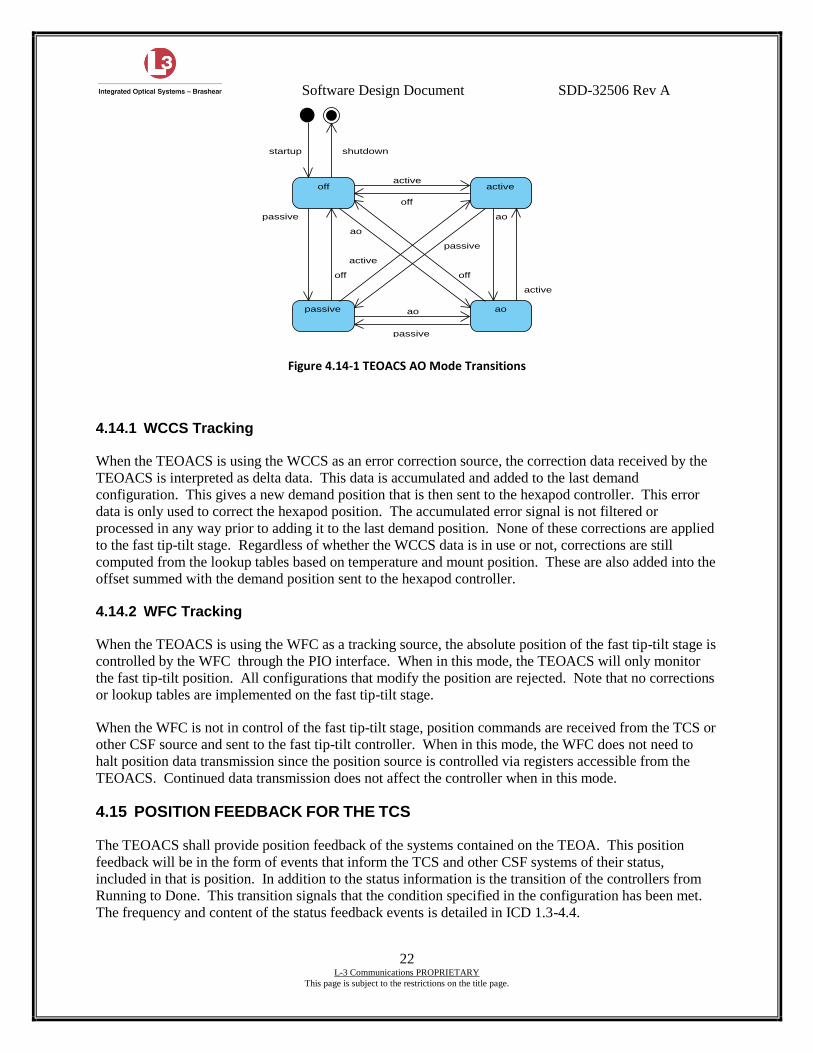
Software Design Document SDD-32506 Rev A
22 L-3 Communications PROPRIETARY
This page is subject to the restrictions on the title page.
Figure 4.14-1 TEOACS AO Mode Transitions
4.14.1 WCCS Tracking
When the TEOACS is using the WCCS as an error correction source, the correction data received by the
TEOACS is interpreted as delta data. This data is accumulated and added to the last demand
configuration. This gives a new demand position that is then sent to the hexapod controller. This error
data is only used to correct the hexapod position. The accumulated error signal is not filtered or
processed in any way prior to adding it to the last demand position. None of these corrections are applied
to the fast tip-tilt stage. Regardless of whether the WCCS data is in use or not, corrections are still
computed from the lookup tables based on temperature and mount position. These are also added into the
offset summed with the demand position sent to the hexapod controller.
4.14.2 WFC Tracking
When the TEOACS is using the WFC as a tracking source, the absolute position of the fast tip-tilt stage is
controlled by the WFC through the PIO interface. When in this mode, the TEOACS will only monitor
the fast tip-tilt position. All configurations that modify the position are rejected. Note that no corrections
or lookup tables are implemented on the fast tip-tilt stage.
When the WFC is not in control of the fast tip-tilt stage, position commands are received from the TCS or
other CSF source and sent to the fast tip-tilt controller. When in this mode, the WFC does not need to
halt position data transmission since the position source is controlled via registers accessible from the
TEOACS. Continued data transmission does not affect the controller when in this mode.
4.15 POSITION FEEDBACK FOR THE TCS
The TEOACS shall provide position feedback of the systems contained on the TEOA. This position
feedback will be in the form of events that inform the TCS and other CSF systems of their status,
included in that is position. In addition to the status information is the transition of the controllers from
Running to Done. This transition signals that the condition specified in the configuration has been met.
The frequency and content of the status feedback events is detailed in ICD 1.3-4.4.
ao
active
passive
off
passive
active
shutdownstartup
off
ao
passive
active
ao
off
active
ao
off
passive
Software Design Document SDD-32506 Rev A
23 L-3 Communications PROPRIETARY
This page is subject to the restrictions on the title page.
4.16 HARDWARE LIMITS
As much as possible, the TEOACS shall make use of any and all safety features of the base hardware
controllers (supplied by Physik Instrumente). When available, the following limits will be use to
maintain safe operation within the operational range.
Hardware Limits – Limit switches that remove power from the motors to prevent operation of the
actuator beyond design limits.
Software Limits – Limits in software that are imposed on the controllers and are intended to
maintain operation within safe limits. The software limits are programmable and shall be stored
in the property database.
The Lyot stop has two limit switches indicating the two positions of travel. Should both switches become
activated at the same time (indicating both open and closed), the TEOACS will flag this condition as an
error, disable the Lyot stop, and change its health to BAD.
4.17 FAILURE MODES
This section describes possible failure modes of the TEOACS, how the failures are handled, and potential
consequences.
4.17.1 Responding to Invalid Data
Attributes sent to the TEOACS are automatically range checked using the property DB. Configurations
consisting of multiple attributes are checked for consistency. If either of these checks fails, the
configuration is rejected.
The first of these checks could fail if the property DB were incorrectly configured and allowed a value to
be entered outside of a normal range. The second check could fail if the coding was done incorrectly and
allowed an inconsistent configuration to be executed. In either case, the hardware would not be at risk of
damage due to the limits imposed on the system by the actual hardware. The actuators cannot be driven
past their physical limit switches without the actuators being disabled.
Should the invalid data cause the CSF controller to crash, it is presumed that the loss of the cStatus
message from the controller would be noticed by the recipient and an alarm would be raised or it would
change its health status.
4.17.2 Responding to Invalid Trajectory Data
Should the TEOACS receive invalid data from the WCCS, it will be range-checked prior to being sent to
the hexapod. Should the range check succeed (i.e. bad property ranges) and the data is used, the internal
limits on the hexapod will prevent the actuators from moving beyond their normal operating range.
In the case of the WFC, that data is sent directly to the fast tip-tilt controller and is not range checked by
the TEOACS. Should this data be outside of the operational range, the fast tip-tilt controller will limit the
motion and maintain it inside of a safe range.

Software Design Document SDD-32506 Rev A
24 L-3 Communications PROPRIETARY
This page is subject to the restrictions on the title page.
4.17.3 Internal Failures
The TEOACS is required to monitor the state of its sub-controllers and reflect any failures of these sub-
controllers. Failure here is in respect to a failure in sub-controller processing, not a failure of an actual
hardware controller, hardware failures are coved in section 4.17.4.
The TEOACS top-level ManagementController atst.tcs.teoacs is responsible for maintaining a record of
the state of its sub-controllers and for maintaining open connections to them for submission of
configurations. Each sub-controller present in the TEOACS system will post a cStatus event at 1Hz.
This will contain status specific to its operations, e.g. position of hardware, etc. The atst.tcs.teoacs top-
level controller will subscribe to these events and, if they do not arrive, it will attempt to determine the
cause. If communications with the sub-controller can no longer be established, the atst.tcs.teoacs
controller will set its health BAD with a message explaining the cause.
4.17.4 Failures of TEOA Hardware
The TEOACS can only control the M2 hardware through its connection to the hexapod and fast tip-tilt
controllers. If these connections fail or the hardware controllers report an internal failure, the appropriate
TEOA sub-controller will set its health to BAD with a message explaining the cause.
If a connection failure occurs, the sub-controller using that connection will discover this when it attempts
to write data to the hardware controller or read status.
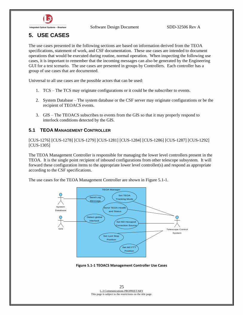
Software Design Document SDD-32506 Rev A
25 L-3 Communications PROPRIETARY
This page is subject to the restrictions on the title page.
5. USE CASES
The use cases presented in the following sections are based on information derived from the TEOA
specifications, statement of work, and CSF documentation. These use cases are intended to document
operations that would be executed during routine, normal operation. When inspecting the following use
cases, it is important to remember that the incoming messages can also be generated by the Engineering
GUI for a test scenario. The use cases are presented in groups by Controllers. Each controller has a
group of use cases that are documented.
Universal to all use cases are the possible actors that can be used:
1. TCS – The TCS may originate configurations or it could be the subscriber to events.
2. System Database – The system database or the CSF server may originate configurations or be the
recipient of TEOACS events.
3. GIS – The TEOACS subscribes to events from the GIS so that it may properly respond to
interlock conditions detected by the GIS.
5.1 TEOA MANAGEMENT CONTROLLER
[CUS-1276] [CUS-1278] [CUS-1279] [CUS-1281] [CUS-1284] [CUS-1286] [CUS-1287] [CUS-1292]
[CUS-1305]
The TEOA Management Controller is responsible for managing the lower level controllers present in the
TEOA. It is the single point recipient of inbound configurations from other telescope subsystem. It will
forward these configuration items to the appropriate lower level controller(s) and respond as appropriate
according to the CSF specifications.
The use cases for the TEOA Management Controller are shown in Figure 5.1-1.
Figure 5.1-1 TEOACS Management Controller Use Cases
Set TEOA
Tracking Mode
Set M2 FTT
Position
Set M2 Hexapod
Correction Source
Set Lyot Stop
Position
GIS
Detect global
interlock
System
Database
Telescope Control
System
Send TEOA Health
and Status
Send Log
Message
TEOA Manager
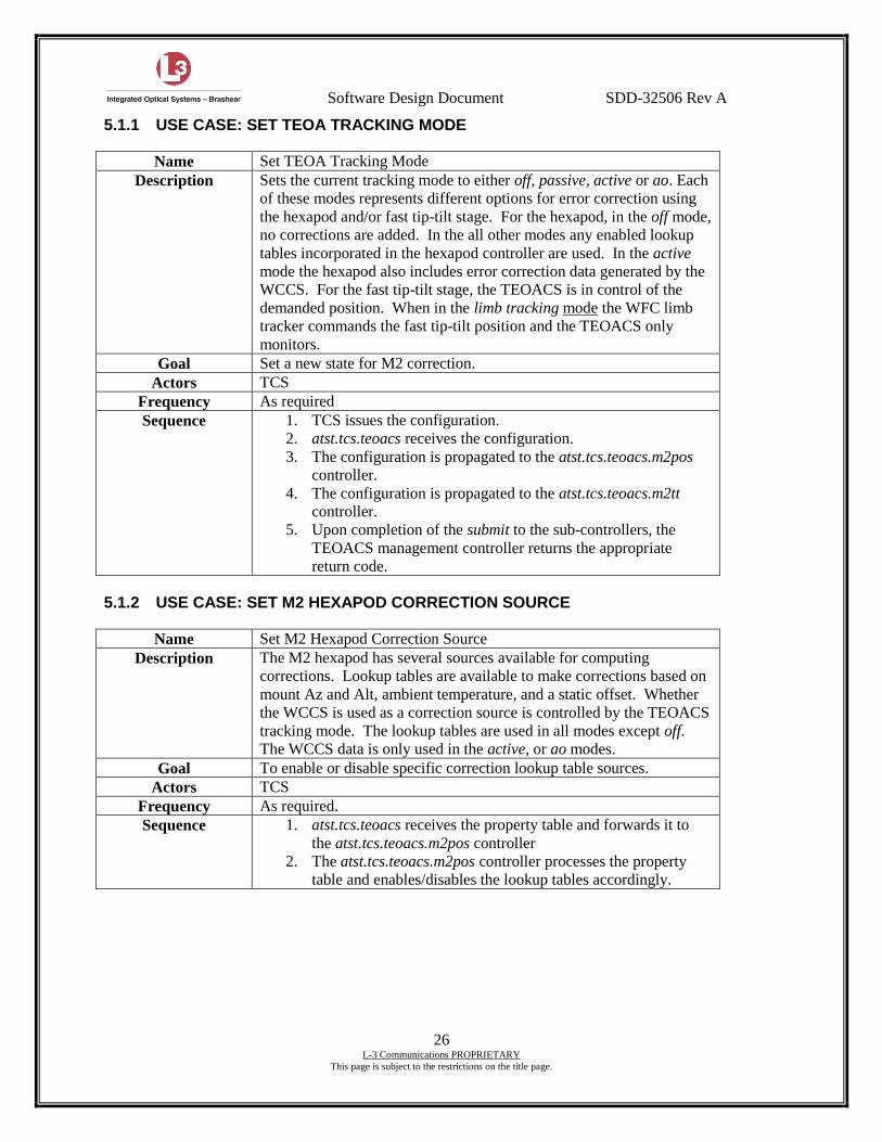
Software Design Document SDD-32506 Rev A
26 L-3 Communications PROPRIETARY
This page is subject to the restrictions on the title page.
5.1.1 USE CASE: SET TEOA TRACKING MODE
Name Set TEOA Tracking Mode
Description Sets the current tracking mode to either off, passive, active or ao. Each
of these modes represents different options for error correction using
the hexapod and/or fast tip-tilt stage. For the hexapod, in the off mode,
no corrections are added. In the all other modes any enabled lookup
tables incorporated in the hexapod controller are used. In the active
mode the hexapod also includes error correction data generated by the
WCCS. For the fast tip-tilt stage, the TEOACS is in control of the
demanded position. When in the limb tracking mode the WFC limb
tracker commands the fast tip-tilt position and the TEOACS only
monitors.
Goal Set a new state for M2 correction.
Actors TCS
Frequency As required
Sequence 1. TCS issues the configuration.
2. atst.tcs.teoacs receives the configuration.
3. The configuration is propagated to the atst.tcs.teoacs.m2pos
controller.
4. The configuration is propagated to the atst.tcs.teoacs.m2tt
controller.
5. Upon completion of the submit to the sub-controllers, the
TEOACS management controller returns the appropriate
return code.
5.1.2 USE CASE: SET M2 HEXAPOD CORRECTION SOURCE
Name Set M2 Hexapod Correction Source
Description The M2 hexapod has several sources available for computing
corrections. Lookup tables are available to make corrections based on
mount Az and Alt, ambient temperature, and a static offset. Whether
the WCCS is used as a correction source is controlled by the TEOACS
tracking mode. The lookup tables are used in all modes except off.
The WCCS data is only used in the active, or ao modes.
Goal To enable or disable specific correction lookup table sources.
Actors TCS
Frequency As required.
Sequence 1. atst.tcs.teoacs receives the property table and forwards it to
the atst.tcs.teoacs.m2pos controller
2. The atst.tcs.teoacs.m2pos controller processes the property
table and enables/disables the lookup tables accordingly.
Software Design Document SDD-32506 Rev A
27 L-3 Communications PROPRIETARY
This page is subject to the restrictions on the title page.
5.1.3 USE CASE: SET M2 HEXAPOD POSITION
Name Set M2 Hexapod Position
Description A new position for the M2 hexapod is demanded by the TCS. This
position is ultimately sent to the M-850 controller. The position can
be either numeric data or a named position. In the case of a named
position, the name is used to look up numeric positions in the system
database. When using a named position, the M2 Hexapod Controller
will be responsible for retrieving the information from the system
database.
Goal Set a new position for the hexapod and move it.
Actors TCS
Frequency As required.
Sequence 1. atst.tcs.teoacs receives the configuration and forwards it to the
atst.tcs.teoacs.m2pos controller
2. The atst.tcs.teoacs.m2pos controller processes the
configuration and attempts to match it.
3. If the state is running, a new position is computed using the
current correction offsets and sent to the hexapod for
positioning.
4. An appropriate return code is sent back to the management
controller.
5. The management controller sends the DONE response.
5.1.4 USE CASE: SET M2 FTT POSITION
Name Set M2 Fast Tip-tilt Position
Description A new position for the M2 fast tip-tilt stage is demanded by the TCS.
This position is ultimately sent to the E-712 controller. In the case of a
named position, the name is used to look up numeric positions in the
system database. When using a named position, the M2 Fast Tip-tilt
Controller will be responsible for retrieving the information from the
system database.
Goal Set a new position for the fast tip-tilt stage and move it.
Actors TCS
Frequency As required.
Sequence 1. atst.tcs.teoacs receives the configuration and forwards it to the
atst.tcs.teoacs.m2tt controller
2. The atst.tcs.teoacs.m2tt controller processes the configuration
and attempts to match it.
3. If the state is running, a new position is sent to the fast tip-tilt
controller for positioning.
4. An appropriate return code is sent back to the management
controller.
5. The management controller sends the DONE response.
Software Design Document SDD-32506 Rev A
28 L-3 Communications PROPRIETARY
This page is subject to the restrictions on the title page.
5.1.5 USE CASE: SET LYOT STOP POSITION
Name Set Lyot Stop Position
Description A new position for the Lyot stop is demanded by the TCS. This new
position is implemented by setting the appropriate digital outputs on
the digital I/O module.
Goal Set a new position for the hexapod
Actors TCS
Frequency As required.
Sequence 1. atst.tcs.teoacs receives the configuration and forwards it to the
atst.tcs.teoacs.lyot controller
2. The atst.tcs.teoacs.lyot controller processes the configuration
and attempts to match it.
3. If the state is running, a new position commanded using the
digital I/O module. The command is verified by examining
the digital inputs from the Lyot stop position switches.
4. An appropriate return code is sent back to the management
controller.
5. The management controller sends the DONE response.
5.1.6 USE CASE: SEND LOG MESSAGE
Name Send Log Message
Description Send a log message to the system database. The message is sent using
the CSF event facility and is archived in the system database.
Goal Send a message and archive it in the system database.
Actors System Database
Frequency As required.
Sequence 1. The atst.tcs.teoacs controller formats a message for
transmission.
2. The message is sent to the system database using the CSF
messaging facility.
5.1.7 USE CASE: TEOA MANAGER DETECT GLOBAL INTERLOCK
Name TEOA Manager Detect Global Interlock
Description Detect the presence of a global interlock from the GIS controller via a
subscribed event. Upon receipt of an event notifying the TEOA
Management Controller of a GIS event, take the necessary action to
put the Management Controller into the default state.
Goal Detect a GIS event and place the TEOA Management Controller into a
default state.
Actors GIS
Frequency As required.
Sequence 1. The atst.tcs.teoacs controller receives notification of a GIS
event via a subscribed message event.
2. The management controller goes into the default state.
3. The management controller updates its health and status to
reflect the change to default state as a result of a GIS event.
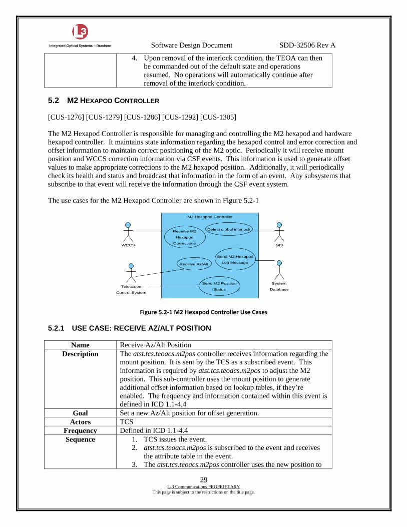
Software Design Document SDD-32506 Rev A
29 L-3 Communications PROPRIETARY
This page is subject to the restrictions on the title page.
4. Upon removal of the interlock condition, the TEOA can then
be commanded out of the default state and operations
resumed. No operations will automatically continue after
removal of the interlock condition.
5.2 M2 HEXAPOD CONTROLLER
[CUS-1276] [CUS-1279] [CUS-1286] [CUS-1292] [CUS-1305]
The M2 Hexapod Controller is responsible for managing and controlling the M2 hexapod and hardware
hexapod controller. It maintains state information regarding the hexapod control and error correction and
offset information to maintain correct positioning of the M2 optic. Periodically it will receive mount
position and WCCS correction information via CSF events. This information is used to generate offset
values to make appropriate corrections to the M2 hexapod position. Additionally, it will periodically
check its health and status and broadcast that information in the form of an event. Any subsystems that
subscribe to that event will receive the information through the CSF event system.
The use cases for the M2 Hexapod Controller are shown in Figure 5.2-1
Figure 5.2-1 M2 Hexapod Controller Use Cases
5.2.1 USE CASE: RECEIVE AZ/ALT POSITION
Name Receive Az/Alt Position
Description The atst.tcs.teoacs.m2pos controller receives information regarding the
mount position. It is sent by the TCS as a subscribed event. This
information is required by atst.tcs.teoacs.m2pos to adjust the M2
position. This sub-controller uses the mount position to generate
additional offset information based on lookup tables, if they’re
enabled. The frequency and information contained within this event is
defined in ICD 1.1-4.4
Goal Set a new Az/Alt position for offset generation.
Actors TCS
Frequency Defined in ICD 1.1-4.4
Sequence 1. TCS issues the event.
2. atst.tcs.teoacs.m2pos is subscribed to the event and receives
the attribute table in the event.
3. The atst.tcs.teoacs.m2pos controller uses the new position to
Detect global interlock
GISWCCS
Receive M2
Hexapod
Corrections
Receive Az/Alt
Send M2 Position
Status
Send M2 Hexapod
Log Message
System
DatabaseTelescope
Control System
M2 Hexapod Controller
Software Design Document SDD-32506 Rev A
30 L-3 Communications PROPRIETARY
This page is subject to the restrictions on the title page.
generate new lookup table offsets and sets the M2 position as
needed.
5.2.2 USE CASE: SEND M2 HEXAPOD CONTROLLER STATUS
Name Send M2 Hexapod Controller Health and Status
Description Sends the current M2 Hexapod Controller health and status
information as a CSF event. The frequency and information contained
in this message is defined by ICD 1.3-4.4
Goal To inform other systems of the health and status of the M2 Hexapod
Controller.
Actors TCS
Frequency Defined by ICD 1.3-4.4
Sequence 1. The atst.tcs.teoacs.m2pos controller uses the default posting
tab to determine when the next event is to go out.
2. atst.tcs.teoacs.m2pos event callback is called by the default
posting tab that assembles all the necessary information that
goes in the event.
3. The information is published in an event, to which interested
subsystems have subscribed.
5.2.3 USE CASE: SEND M2 HEXAPOD LOG MESSAGE
Name Send M2 Hexapod Log Message
Description Send a log message to the system database. The message is sent using
the CSF event facility and is archived in the system database.
Goal Send a message and archive it in the system database.
Actors System Database
Frequency As required.
Sequence 1. The atst.tcs.teoacs.m2pos controller formats a message for
transmission.
2. The message is sent to the system database using the CSF
messaging facility.
Software Design Document SDD-32506 Rev A
31 L-3 Communications PROPRIETARY
This page is subject to the restrictions on the title page.
5.2.4 USE CASE: RECEIVE M2 HEXAPOD CORRECTIONS
Name Receive M2 Hexapod Corrections
Description When in an active or AO mode, the M2 hexapod is required to follow
correction data as generated by the WCCS. This information is
broadcast by the WCCS in the form of a CSF event, to which the
atst.tcs.teoacs.m2pos controller must subscribe. The attributes
contained within this event are delta values which the M2 Hexapod
Controller must accumulate and apply to the demanded hexapod
position. In addition, if enabled, offsets generated from the lookup
tables must also be added before commanding the position on the M-
850 controller.
Goal Receive the hexapod corrections required, as generated by the WCCS.
The frequency and information contained within the event received
from the WCCS is defined in ICD 1.3-2.3.
Actors WCCS
Frequency Defined in ICD 1.3-2.3
Sequence 1. Receive WCCS M2 Correction event.
2. Accumulate correction data.
3. Compute new offset from lookup tables in use.
4. Sum correction, offset, and demand position.
5. Send new position to M-850 controller.
5.2.5 USE CASE: M2 HEXAPOD CONTROLLER DETECT GLOBAL INTERLOCK
Name M2 Hexapod Controller Detect Global Interlock
Description Detect the presence of a global interlock from the GIS controller via a
subscribed event. Upon receipt of an event notifying the M2 Hexapod
Controller of a GIS event, halt motion on the fast tip-tilt stage and put
the M2 Fast Tip-tilt Controller into the default state.
Goal Detect a GIS event, halt motion on the hexapod, and place the M2
Hexapod Controller into a default state.
Actors GIS
Frequency As required.
Sequence 1. The atst.tcs.teoacs.m2pos controller receives notification of a
GIS event via a subscribed message event.
2. The M2 Hexapod Controller commands the M-850 controller
to halt motion and turn off amplifiers if possible.
3. The M2 Hexapod Controller goes into the default state.
4. The M2 Hexapod Controller updates its health and status to
reflect the change to default state as a result of a GIS event.
5. Upon removal of the interlock condition, the M2 Hexapod
Controller can then be commanded out of the default state and
operations resumed. No operations will automatically
continue after removal of the interlock condition.
5.3 M2 FAST TIP-TILT CONTROLLER
[CUS-1276] [CUS-1278] [CUS-1305]
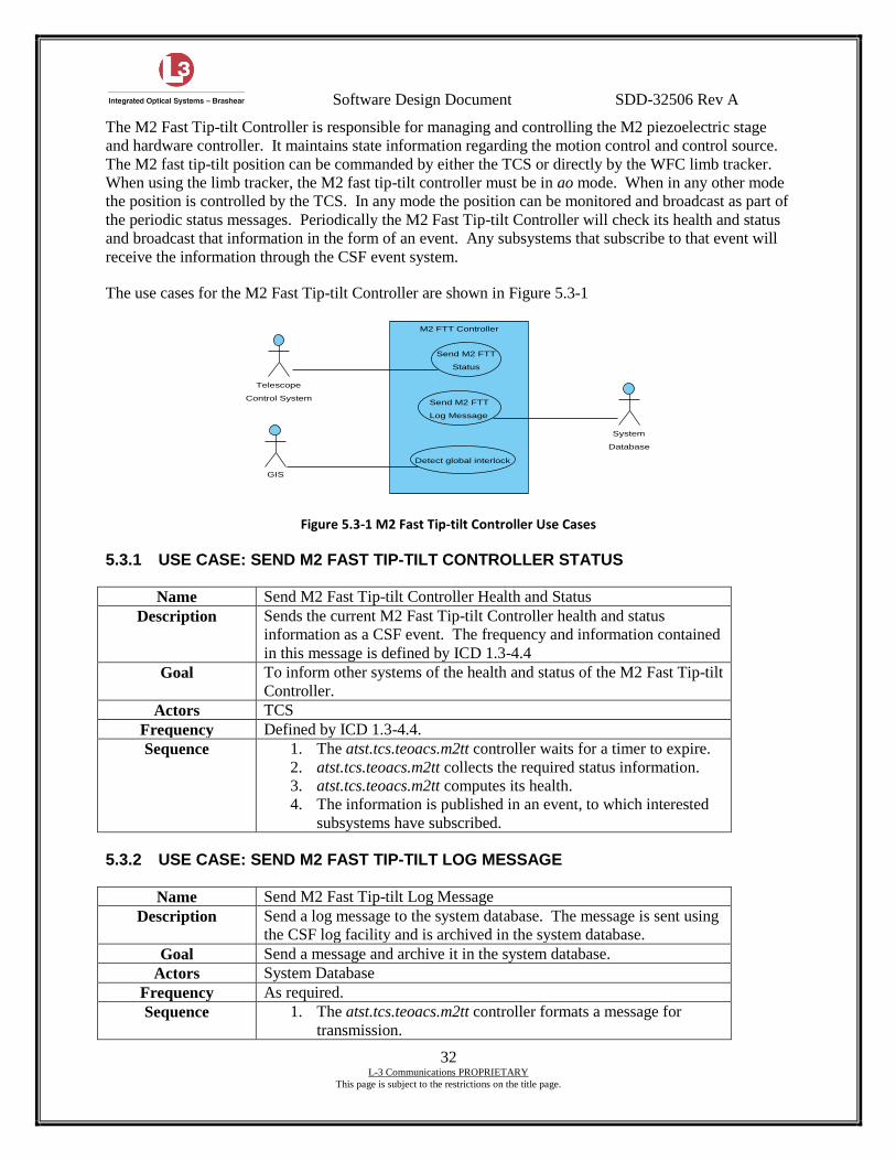
Software Design Document SDD-32506 Rev A
32 L-3 Communications PROPRIETARY
This page is subject to the restrictions on the title page.
The M2 Fast Tip-tilt Controller is responsible for managing and controlling the M2 piezoelectric stage
and hardware controller. It maintains state information regarding the motion control and control source.
The M2 fast tip-tilt position can be commanded by either the TCS or directly by the WFC limb tracker.
When using the limb tracker, the M2 fast tip-tilt controller must be in ao mode. When in any other mode
the position is controlled by the TCS. In any mode the position can be monitored and broadcast as part of
the periodic status messages. Periodically the M2 Fast Tip-tilt Controller will check its health and status
and broadcast that information in the form of an event. Any subsystems that subscribe to that event will
receive the information through the CSF event system.
The use cases for the M2 Fast Tip-tilt Controller are shown in Figure 5.3-1
Figure 5.3-1 M2 Fast Tip-tilt Controller Use Cases
5.3.1 USE CASE: SEND M2 FAST TIP-TILT CONTROLLER STATUS
Name Send M2 Fast Tip-tilt Controller Health and Status
Description Sends the current M2 Fast Tip-tilt Controller health and status
information as a CSF event. The frequency and information contained
in this message is defined by ICD 1.3-4.4
Goal To inform other systems of the health and status of the M2 Fast Tip-tilt
Controller.
Actors TCS
Frequency Defined by ICD 1.3-4.4.
Sequence 1. The atst.tcs.teoacs.m2tt controller waits for a timer to expire.
2. atst.tcs.teoacs.m2tt collects the required status information.
3. atst.tcs.teoacs.m2tt computes its health.
4. The information is published in an event, to which interested
subsystems have subscribed.
5.3.2 USE CASE: SEND M2 FAST TIP-TILT LOG MESSAGE
Name Send M2 Fast Tip-tilt Log Message
Description Send a log message to the system database. The message is sent using
the CSF log facility and is archived in the system database.
Goal Send a message and archive it in the system database.
Actors System Database
Frequency As required.
Sequence 1. The atst.tcs.teoacs.m2tt controller formats a message for
transmission.
Detect global interlock
GIS
Send M2 FTT
Log Message
Send M2 FTT
Status
System
Database
Telescope
Control System
M2 FTT Controller
Software Design Document SDD-32506 Rev A
33 L-3 Communications PROPRIETARY
This page is subject to the restrictions on the title page.
2. The message is sent to the system database using the CSF log
facility.
5.3.3 USE CASE: M2 FAST TIP-TILT DETECT GLOBAL INTERLOCK
Name M2 Fast Tip-tilt Detect Global Interlock
Description Detect the presence of a global interlock from the GIS controller via a
subscribed event. Upon receipt of an event notifying the M2 Fast Tip-
tilt Controller of a GIS event, halt motion on the fast tip-tilt stage and
put the M2 Fast Tip-tilt Controller into the default state.
Goal Detect a GIS event, halt motion on the FTT stage, and place the M2
Fast Tip-tilt Controller into a default state.
Actors GIS
Frequency As required.
Sequence 6. The atst.tcs.teoacs.m2tt controller receives notification of a
GIS event via a subscribed message event.
7. The M2 Fast Tip-tilt Controller commands the E-712
controller to halt motion and turn off amplifiers if possible.
8. The M2 Fast Tip-tilt Controller goes into the default state.
9. The M2 Fast Tip-tilt Controller updates its health and status to
reflect the change to default state as a result of a GIS event.
10. Upon removal of the interlock condition, the M2 Fast Tip-tilt
Controller can then be commanded out of the default state and
operations resumed. No operations will automatically
continue after removal of the interlock condition.
5.4 LYOT STOP CONTROLLER
[CUS-1276] [CUS-1281] [CUS-1284] [CUS-1305]
The Lyot Stop Controller is responsible for managing and controlling the position of the Lyot stop. The
position is controlled by using an electrically controlled pneumatic actuator that drives the position of the
Lyot stop. The actual position is read back through switches that sense the position of the stop. The
discrete inputs and outputs are connected to an Ethernet based digital I/O controller. This controller is
driven from the TEOACS through a driver that is interfaced to the CSF architecture. Periodically the
Lyot Stop Controller will check its health and status and broadcast that information in the form of an
event. Any subsystems that subscribe to that event will receive the information through the CSF event
system.
The use cases for the Lyot Stop Controller are shown in Figure 5.4-1
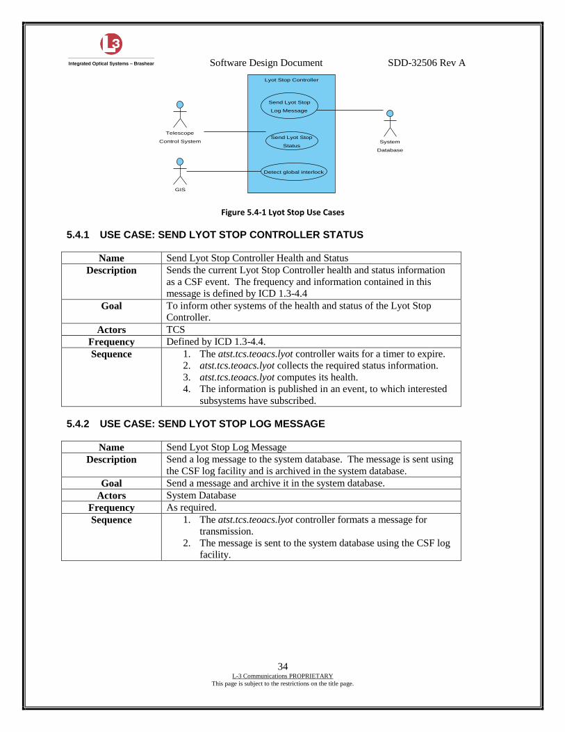
Software Design Document SDD-32506 Rev A
34 L-3 Communications PROPRIETARY
This page is subject to the restrictions on the title page.
Figure 5.4-1 Lyot Stop Use Cases
5.4.1 USE CASE: SEND LYOT STOP CONTROLLER STATUS
Name Send Lyot Stop Controller Health and Status
Description Sends the current Lyot Stop Controller health and status information
as a CSF event. The frequency and information contained in this
message is defined by ICD 1.3-4.4
Goal To inform other systems of the health and status of the Lyot Stop
Controller.
Actors TCS
Frequency Defined by ICD 1.3-4.4.
Sequence 1. The atst.tcs.teoacs.lyot controller waits for a timer to expire.
2. atst.tcs.teoacs.lyot collects the required status information.
3. atst.tcs.teoacs.lyot computes its health.
4. The information is published in an event, to which interested
subsystems have subscribed.
5.4.2 USE CASE: SEND LYOT STOP LOG MESSAGE
Name Send Lyot Stop Log Message
Description Send a log message to the system database. The message is sent using
the CSF log facility and is archived in the system database.
Goal Send a message and archive it in the system database.
Actors System Database
Frequency As required.
Sequence 1. The atst.tcs.teoacs.lyot controller formats a message for
transmission.
2. The message is sent to the system database using the CSF log
facility.
Detect global interlock
GIS
Send Lyot Stop
Log Message
Send Lyot Stop
Status
Telescope
Control System System
Database
Lyot Stop Controller
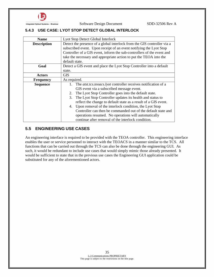
Software Design Document SDD-32506 Rev A
35 L-3 Communications PROPRIETARY
This page is subject to the restrictions on the title page.
5.4.3 USE CASE: LYOT STOP DETECT GLOBAL INTERLOCK
Name Lyot Stop Detect Global Interlock
Description Detect the presence of a global interlock from the GIS controller via a
subscribed event. Upon receipt of an event notifying the Lyot Stop
Controller of a GIS event, inform the sub-controllers of the event and
take the necessary and appropriate action to put the TEOA into the
default state.
Goal Detect a GIS event and place the Lyot Stop Controller into a default
state.
Actors GIS
Frequency As required.
Sequence 1. The atst.tcs.teoacs.lyot controller receives notification of a
GIS event via a subscribed message event.
2. The Lyot Stop Controller goes into the default state.
3. The Lyot Stop Controller updates its health and status to
reflect the change to default state as a result of a GIS event.
4. Upon removal of the interlock condition, the Lyot Stop
Controller can then be commanded out of the default state and
operations resumed. No operations will automatically
continue after removal of the interlock condition.
5.5 ENGINEERING USE CASES
An engineering interface is required to be provided with the TEOA controller. This engineering interface
enables the user or service personnel to interact with the TEOACS in a manner similar to the TCS. All
functions that can be carried out through the TCS can also be done through the engineering GUI. As
such, it would be redundant to include use cases that would simply mimic those already presented. It
would be sufficient to state that in the previous use cases the Engineering GUI application could be
substituted for any of the aforementioned actors.
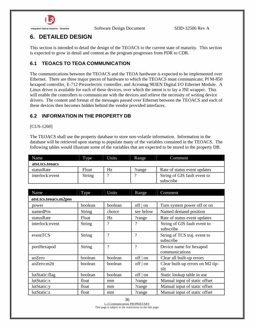
Software Design Document SDD-32506 Rev A
36 L-3 Communications PROPRIETARY
This page is subject to the restrictions on the title page.
6. DETAILED DESIGN
This section is intended to detail the design of the TEOACS to the current state of maturity. This section
is expected to grow in detail and content as the program progresses from PDR to CDR.
6.1 TEOACS TO TEOA COMMUNICATION
The communications between the TEOACS and the TEOA hardware is expected to be implemented over
Ethernet. There are three major pieces of hardware to which the TEOACS must communicate; PI M-850
hexapod controller, E-712 Piezoelectric controller, and Acromag 983EN Digital I/O Ethernet Module. A
Linux driver is available for each of these devices, over which the intent is to lay a JNI wrapper. This
will enable the controllers to communicate with the devices and relieve the necessity of writing device
drivers. The content and format of the messages passed over Ethernet between the TEOACS and each of
these devices then becomes hidden behind the vendor provided interfaces.
6.2 INFORMATION IN THE PROPERTY DB
[CUS-1260]
The TEOACS shall use the property database to store non-volatile information. Information in the
database will be retrieved upon startup to populate many of the variables contained in the TEOACS. The
following tables would illustrate some of the variables that are expected to be stored in the property DB.
Name Type Units Range Comment
atst.tcs.teoacs
statusRate Float Hz ?range Rate of status event updates
interlock:event String ? ? String of GIS fault event to
subscribe
Name Type Units Range Comment
atst.tcs.teoacs.m2pos
power boolean boolean off | on Turn system power off or on
namedPos String choice see below Named demand position
statusRate Float Hz ?range Rate of status event updates
interlock:event String ? ? String of GIS fault event to
subscribe
eventTCS String ? ? String of TCS traj. event to
subscribe
portHexapod String ? ? Device name for hexapod
communications
aoZero boolean boolean off | on Clear all built-up errors
aoZero:m2tt boolean boolean off | on Clear built-up errors on M2 tip-
tilt
lutStatic:flag boolean boolean off | on Static lookup table in use
lutStatic:x float mm ?range Manual input of static offset
lutStatic:y float mm ?range Manual input of static offset
lutStatic:z float mm ?range Manual input of static offset
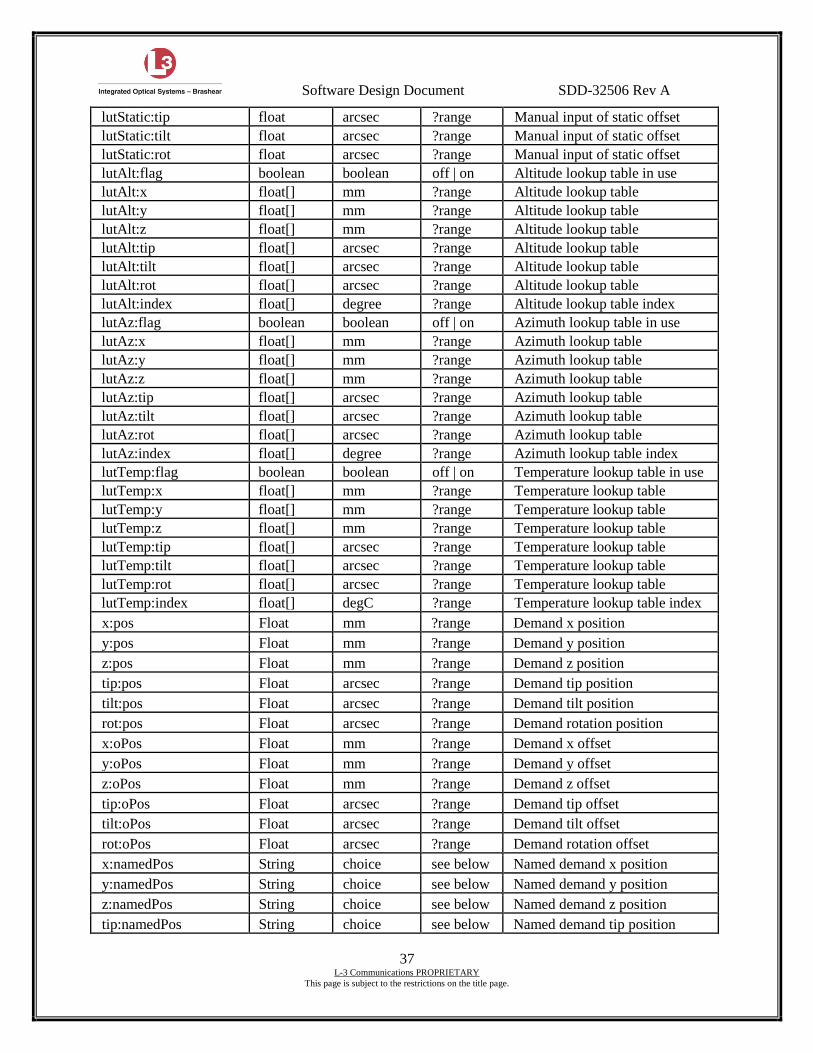
Software Design Document SDD-32506 Rev A
37 L-3 Communications PROPRIETARY
This page is subject to the restrictions on the title page.
lutStatic:tip float arcsec ?range Manual input of static offset
lutStatic:tilt float arcsec ?range Manual input of static offset
lutStatic:rot float arcsec ?range Manual input of static offset
lutAlt:flag boolean boolean off | on Altitude lookup table in use
lutAlt:x float[] mm ?range Altitude lookup table
lutAlt:y float[] mm ?range Altitude lookup table
lutAlt:z float[] mm ?range Altitude lookup table
lutAlt:tip float[] arcsec ?range Altitude lookup table
lutAlt:tilt float[] arcsec ?range Altitude lookup table
lutAlt:rot float[] arcsec ?range Altitude lookup table
lutAlt:index float[] degree ?range Altitude lookup table index
lutAz:flag boolean boolean off | on Azimuth lookup table in use
lutAz:x float[] mm ?range Azimuth lookup table
lutAz:y float[] mm ?range Azimuth lookup table
lutAz:z float[] mm ?range Azimuth lookup table
lutAz:tip float[] arcsec ?range Azimuth lookup table
lutAz:tilt float[] arcsec ?range Azimuth lookup table
lutAz:rot float[] arcsec ?range Azimuth lookup table
lutAz:index float[] degree ?range Azimuth lookup table index
lutTemp:flag boolean boolean off | on Temperature lookup table in use
lutTemp:x float[] mm ?range Temperature lookup table
lutTemp:y float[] mm ?range Temperature lookup table
lutTemp:z float[] mm ?range Temperature lookup table
lutTemp:tip float[] arcsec ?range Temperature lookup table
lutTemp:tilt float[] arcsec ?range Temperature lookup table
lutTemp:rot float[] arcsec ?range Temperature lookup table
lutTemp:index float[] degC ?range Temperature lookup table index
x:pos Float mm ?range Demand x position
y:pos Float mm ?range Demand y position
z:pos Float mm ?range Demand z position
tip:pos Float arcsec ?range Demand tip position
tilt:pos Float arcsec ?range Demand tilt position
rot:pos Float arcsec ?range Demand rotation position
x:oPos Float mm ?range Demand x offset
y:oPos Float mm ?range Demand y offset
z:oPos Float mm ?range Demand z offset
tip:oPos Float arcsec ?range Demand tip offset
tilt:oPos Float arcsec ?range Demand tilt offset
rot:oPos Float arcsec ?range Demand rotation offset
x:namedPos String choice see below Named demand x position
y:namedPos String choice see below Named demand y position
z:namedPos String choice see below Named demand z position
tip:namedPos String choice see below Named demand tip position
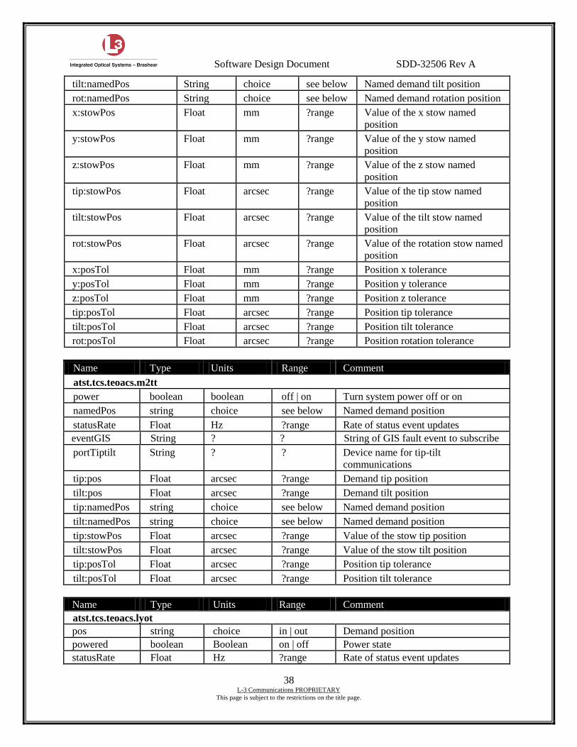
Software Design Document SDD-32506 Rev A
38 L-3 Communications PROPRIETARY
This page is subject to the restrictions on the title page.
tilt:namedPos String choice see below Named demand tilt position
rot:namedPos String choice see below Named demand rotation position
x:stowPos Float mm ?range Value of the x stow named
position
y:stowPos Float mm ?range Value of the y stow named
position
z:stowPos Float mm ?range Value of the z stow named
position
tip:stowPos Float arcsec ?range Value of the tip stow named
position
tilt:stowPos Float arcsec ?range Value of the tilt stow named
position
rot:stowPos Float arcsec ?range Value of the rotation stow named
position
x:posTol Float mm ?range Position x tolerance
y:posTol Float mm ?range Position y tolerance
z:posTol Float mm ?range Position z tolerance
tip:posTol Float arcsec ?range Position tip tolerance
tilt:posTol Float arcsec ?range Position tilt tolerance
rot:posTol Float arcsec ?range Position rotation tolerance
Name Type Units Range Comment
atst.tcs.teoacs.m2tt
power boolean boolean off | on Turn system power off or on
namedPos string choice see below Named demand position
statusRate Float Hz ?range Rate of status event updates
eventGIS String ? ? String of GIS fault event to subscribe
portTiptilt String ? ? Device name for tip-tilt
communications
tip:pos Float arcsec ?range Demand tip position
tilt:pos Float arcsec ?range Demand tilt position
tip:namedPos string choice see below Named demand position
tilt:namedPos string choice see below Named demand position
tip:stowPos Float arcsec ?range Value of the stow tip position
tilt:stowPos Float arcsec ?range Value of the stow tilt position
tip:posTol Float arcsec ?range Position tip tolerance
tilt:posTol Float arcsec ?range Position tilt tolerance
Name Type Units Range Comment
atst.tcs.teoacs.lyot
pos string choice in | out Demand position
powered boolean Boolean on | off Power state
statusRate Float Hz ?range Rate of status event updates
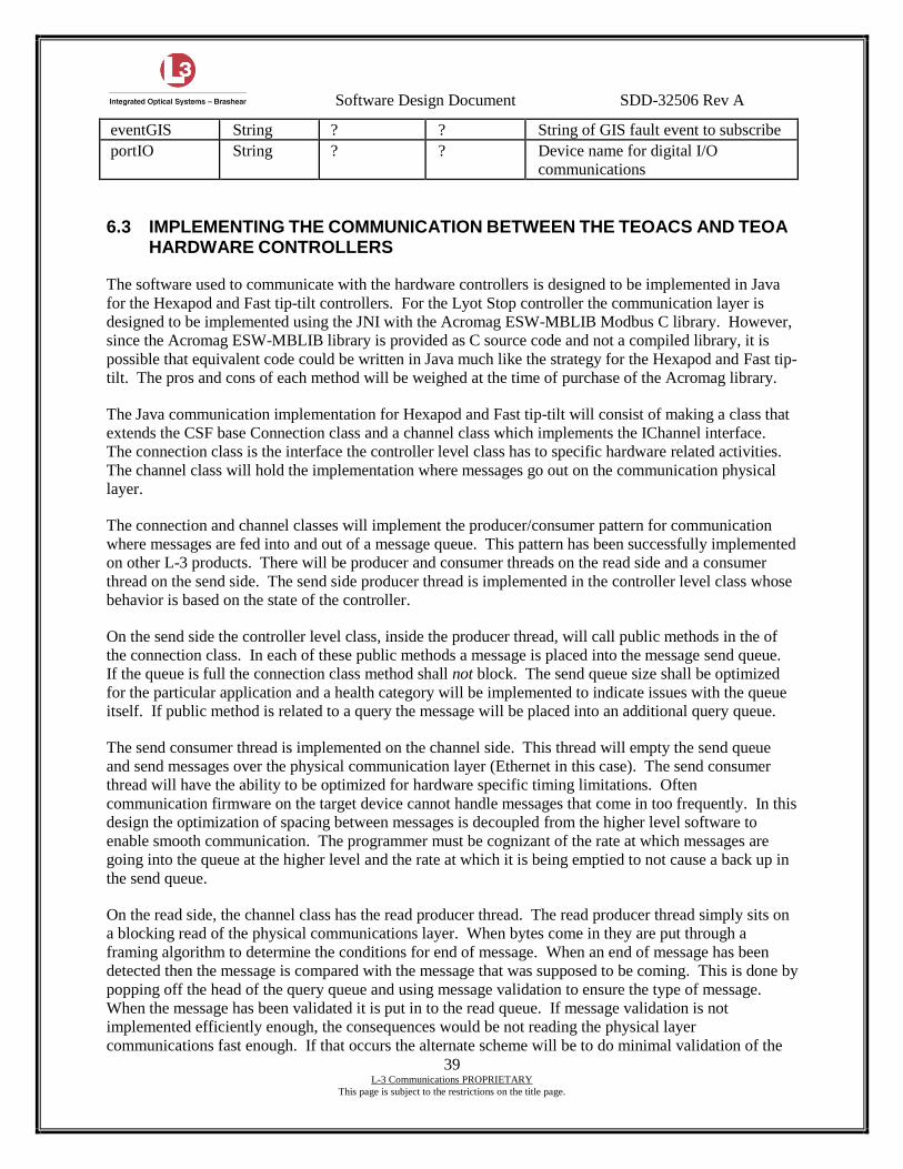
Software Design Document SDD-32506 Rev A
39 L-3 Communications PROPRIETARY
This page is subject to the restrictions on the title page.
eventGIS String ? ? String of GIS fault event to subscribe
portIO String ? ? Device name for digital I/O
communications
6.3 IMPLEMENTING THE COMMUNICATION BETWEEN THE TEOACS AND TEOA
HARDWARE CONTROLLERS
The software used to communicate with the hardware controllers is designed to be implemented in Java
for the Hexapod and Fast tip-tilt controllers. For the Lyot Stop controller the communication layer is
designed to be implemented using the JNI with the Acromag ESW-MBLIB Modbus C library. However,
since the Acromag ESW-MBLIB library is provided as C source code and not a compiled library, it is
possible that equivalent code could be written in Java much like the strategy for the Hexapod and Fast tip-
tilt. The pros and cons of each method will be weighed at the time of purchase of the Acromag library.
The Java communication implementation for Hexapod and Fast tip-tilt will consist of making a class that
extends the CSF base Connection class and a channel class which implements the IChannel interface.
The connection class is the interface the controller level class has to specific hardware related activities.
The channel class will hold the implementation where messages go out on the communication physical
layer.
The connection and channel classes will implement the producer/consumer pattern for communication
where messages are fed into and out of a message queue. This pattern has been successfully implemented
on other L-3 products. There will be producer and consumer threads on the read side and a consumer
thread on the send side. The send side producer thread is implemented in the controller level class whose
behavior is based on the state of the controller.
On the send side the controller level class, inside the producer thread, will call public methods in the of
the connection class. In each of these public methods a message is placed into the message send queue.
If the queue is full the connection class method shall not block. The send queue size shall be optimized
for the particular application and a health category will be implemented to indicate issues with the queue
itself. If public method is related to a query the message will be placed into an additional query queue.
The send consumer thread is implemented on the channel side. This thread will empty the send queue
and send messages over the physical communication layer (Ethernet in this case). The send consumer
thread will have the ability to be optimized for hardware specific timing limitations. Often
communication firmware on the target device cannot handle messages that come in too frequently. In this
design the optimization of spacing between messages is decoupled from the higher level software to
enable smooth communication. The programmer must be cognizant of the rate at which messages are
going into the queue at the higher level and the rate at which it is being emptied to not cause a back up in
the send queue.
On the read side, the channel class has the read producer thread. The read producer thread simply sits on
a blocking read of the physical communications layer. When bytes come in they are put through a
framing algorithm to determine the conditions for end of message. When an end of message has been
detected then the message is compared with the message that was supposed to be coming. This is done by
popping off the head of the query queue and using message validation to ensure the type of message.
When the message has been validated it is put in to the read queue. If message validation is not
implemented efficiently enough, the consequences would be not reading the physical layer
communications fast enough. If that occurs the alternate scheme will be to do minimal validation of the
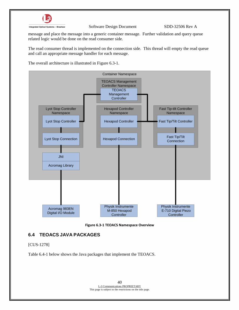
Software Design Document SDD-32506 Rev A
40 L-3 Communications PROPRIETARY
This page is subject to the restrictions on the title page.
message and place the message into a generic container message. Further validation and query queue
related logic would be done on the read consumer side.
The read consumer thread is implemented on the connection side. This thread will empty the read queue
and call an appropriate message handler for each message.
The overall architecture is illustrated in Figure 6.3-1.
Container Namespace
Hexapod Controller
Namespace
Fast Tip-tilt Controller
Namespace
Lyot Stop Controller
Namespace
Hexapod Controller Fast Tip/Tilt ControllerLyot Stop Controller
Physik Instrumente
M-850 Hexapod
Controller
Physik Instrumente
E-710 Digital Piezo
Controller
Acromag 983EN
Digital I/O Module
Hexapod ConnectionFast Tip/Tilt
ConnectionLyot Stop Connection
JNI
Acromag Library
TEOACS Management
Controller Namespace
TEOACS
Management
Controller
Figure 6.3-1 TEOACS Namespace Overview
6.4 TEOACS JAVA PACKAGES
[CUS-1278]
Table 6.4-1 below shows the Java packages that implement the TEOACS.

Software Design Document SDD-32506 Rev A
41 L-3 Communications PROPRIETARY
This page is subject to the restrictions on the title page.
Table 6.4-1 Java packages for TEOACS
Java Package Name CSF Controller Supported Description
atst.teoacs atst.tcs.teoacs This package contains the classes that implement the TEOACS management controller.
atst.teoacs.m2pos atst.tcs.teoacs.m2pos This package contains the classes that implement the TEOACS M2 Hexapod controller.
atst.teoacs.m2pos.connections atst.tcs.teoacs.m2pos This package contains the classes that implement the communications layer of the TEOACS M2 Hexapod controller.
atst.teoacs.m2tt atst.tcs.teoacs.m2tt This package contains the classes that implement the TEOACS M2 tip tilt controller.
atst.teoacs.m2tt.connections atst.tcs.teoacs.m2tt This package contains the classes that implement the communications layer of the TEOACS M2 tip tilt controller.
atst.teoacs.lyot atst.tcs.teoacs.lyot This package contains the classes that implement the TEOACS M2 lyot stop controller.
atst.teoacs.lyot.connections atst.tcs.teoacs.lyot This package contains the classes that implement the communications layer of the TEOACS M2 lyot stop controller.
atst.teoacs.interfaces ALL This package contains interfaces that are used throughout the TEOACS.
atst.teoacs.TFault ALL This package contains the implementation of the fault handling system used throughout the TEOACS. Each fault is actually a health category.
atst.teoacs.TMessage ALL This package contains the implementation of the hardware messaging used for communicating with TEOACS hardware controllers. Each message is a Java class with it’s own unique handler and callback context.
atst.teoacs.util ALL This package contains the support classes that are used throughout the TEOACS. Java enumerations, thread abstractions and other utilities are there.
The Java packages seen in Table 6.4-1 above contain the TEOACS application specific classes used to
create the TEOACS controllers. These classes contain the logic of how to translate received
configurations into operations using the communication software layer to the various hardware
controllers. Representative top-level class diagrams are shown in following sections. To see full class
diagrams documenting the interactions of all classes please see Appendix A.
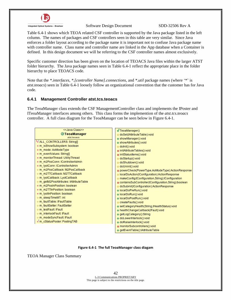
Software Design Document SDD-32506 Rev A
42 L-3 Communications PROPRIETARY
This page is subject to the restrictions on the title page.
Table 6.4-1 shows which TEOA related CSF controller is supported by the Java package listed in the left
column. The names of packages and CSF controllers seen in this table are very similar. Since Java
enforces a folder layout according to the package name it is important not to confuse Java package name
with controller name. Class name and controller name are linked in the App database when a Container is
defined. In this design document we will be referring to the CSF controller names almost exclusively.
Specific customer direction has been given on the location of TEOACS Java files within the larger ATST
folder hierarchy. The Java package names seen in Table 6.4-1 reflect the appropriate place in the folder
hierarchy to place TEOACS code.
Note that the *.interfaces, *.[controller Name].connections, and *.util package names (where ‘*’ is
atst.teoacs) seen in Table 6.4-1 loosely follow an organizational convention that the customer has for Java
code.
6.4.1 Management Controller atst.tcs.teoacs
The TeoaManager class extends the CSF ManagementController class and implements the IPoster and
ITeoaManager interfaces among others. This class forms the implemention of the atst.tcs.teoacs
controller. A full class diagram for the TeoaManager can be seen below in Figure 6.4-1.
Figure 6.4-1 The full TeoaManager class diagam
TEOA Manager Class Summary
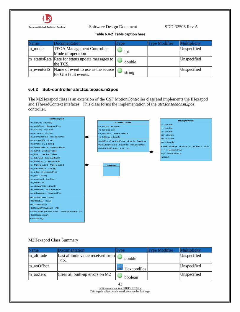
Software Design Document SDD-32506 Rev A
43 L-3 Communications PROPRIETARY
This page is subject to the restrictions on the title page.
Table 6.4-2 Table caption here
Name Documentation Type Type Modifier Multiplicity
m_mode TEOA Management Controller
Mode of operation int
Unspecified
m_statusRate Rate for status update messages to
the TCS. double
Unspecified
m_eventGIS Name of event to use as the source
for GIS fault events. string
Unspecified
6.4.2 Sub-controller atst.tcs.teoacs.m2pos
The M2Hexapod class is an extension of the CSF MotionController class and implements the IHexapod
and IThreadContext intefaces. This class forms the implementation of the atst.tcs.teoacs.m2pos
controller.
M2Hexapod Class Summary
Name Documentation Type Type Modifier Multiplicity
m_altitude Last altitude value received from
TCS. double
Unspecified
m_aoOffset HexapodPos
Unspecified
m_aoZero Clear all built-up errors on M2 boolean
Unspecified
-m_InUse : boolean
-m_Entries : int
-m_Position : HexapodPos
-m_luEntry : double
+AddEntry(LookupEntry : double, Position...
+GetEntry(Value : double) : HexapodPos
+InitTable(Entries : int) : int
LookupTable-x : double
-y : double
-z : double
-tip : double
-tilt : double
-rot : double
+SetPosition(x : double, y : double, z : dou...
++() : HexapodPos
+-() : HexapodPos
+Zero()
HexapodPos
Hexapod
-m_altitude : double
-m_aoOffset : HexapodPos
-m_aoZero : boolean
-m_azimuth : double
-m_demandPos : HexapodPos
-m_eventGIS : string
-m_eventTCS : string
-m_hexapodPos : HexapodPos
-m_lutAlt : LookupTable
-m_lutAz : LookupTable
-m_lutStatic : LookupTable
-m_lutTemp : LookupTable
-m_M2Hexapod : M2Hexapod
-m_namedPos : string[]
-m_offset : HexapodPos
-m_port : string
-m_powered : boolean
-m_state : int
-m_statusRate : double
-m_stowPos : HexapodPos
-m_tolerance : HexapodPos
+EnableCorrections()
+GetStatus() : long
+M2Hexapod()
+SetState(NewState : int)
+SetPosition(NewPosition : HexapodPos) : int
+SetCorrection()
+SetOffset()
M2Hexapod
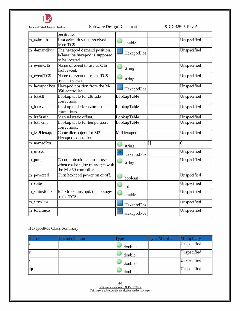
Software Design Document SDD-32506 Rev A
44 L-3 Communications PROPRIETARY
This page is subject to the restrictions on the title page.
positioner
m_azimuth Last azimuth value received
from TCS. double
Unspecified
m_demandPos The hexapod demand position.
Where the hexapod is supposed
to be located.
HexapodPos Unspecified
m_eventGIS Name of event to use as GIS
fault event. string
Unspecified
m_eventTCS Name of event to use as TCS
trajectory event. string
Unspecified
m_hexapodPos Hexapod position from the M-
850 controller. HexapodPos
Unspecified
m_lutAlt Lookup table for altitude
corrections
LookupTable Unspecified
m_lutAz Lookup table for azimuth
corrections.
LookupTable Unspecified
m_lutStatic Manual static offset. LookupTable Unspecified
m_lutTemp Lookup table for temperature
corrections.
LookupTable Unspecified
m_M2Hexapod Controller object for M2
Hexapod controller.
M2Hexapod Unspecified
m_namedPos string
[] 6
m_offset HexapodPos
Unspecified
m_port Communications port to use
when exchanging messages with
the M-850 controller.
string Unspecified
m_powered Turn hexapod power on or off. boolean
Unspecified
m_state int
Unspecified
m_statusRate Rate for status update messages
to the TCS. double
Unspecified
m_stowPos HexapodPos
Unspecified
m_tolerance HexapodPos
Unspecified
HexapodPos Class Summary
Name Documentation Type Type Modifier Multiplicity
x double
Unspecified
y double
Unspecified
z double
Unspecified
tip double
Unspecified
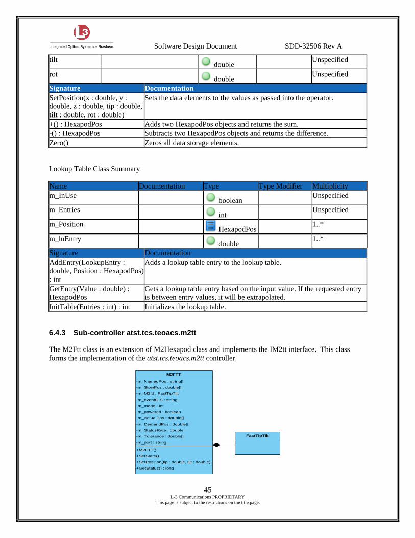
Software Design Document SDD-32506 Rev A
45 L-3 Communications PROPRIETARY
This page is subject to the restrictions on the title page.
tilt double
Unspecified
rot double
Unspecified
Signature Documentation
SetPosition(x : double, y :
double, z : double, tip : double,
tilt : double, rot : double)
Sets the data elements to the values as passed into the operator.
+() : HexapodPos Adds two HexapodPos objects and returns the sum.
-() : HexapodPos Subtracts two HexapodPos objects and returns the difference.
Zero() Zeros all data storage elements.
Lookup Table Class Summary
Name Documentation Type Type Modifier Multiplicity
m_InUse boolean
Unspecified
m_Entries int
Unspecified
m_Position HexapodPos
1..*
m_luEntry double
1..*
Signature Documentation
AddEntry(LookupEntry :
double, Position : HexapodPos)
: int
Adds a lookup table entry to the lookup table.
GetEntry(Value : double) :
HexapodPos
Gets a lookup table entry based on the input value. If the requested entry
is between entry values, it will be extrapolated.
InitTable(Entries : int) : int Initializes the lookup table.
6.4.3 Sub-controller atst.tcs.teoacs.m2tt
The M2Ftt class is an extension of M2Hexapod class and implements the IM2tt interface. This class
forms the implementation of the atst.tcs.teoacs.m2tt controller.
FastTipTilt
-m_NamedPos : string[]
-m_StowPos : double[]
-m_M2ftt : FastTipTilt
-m_eventGIS : string
-m_mode : int
-m_powered : boolean
-m_ActualPos : double[]
-m_DemandPos : double[]
-m_StatusRate : double
-m_Tolerance : double[]
-m_port : string
+M2FTT()
+SetState()
+SetPosition(tip : double, tilt : double)
+GetStatus() : long
M2FTT
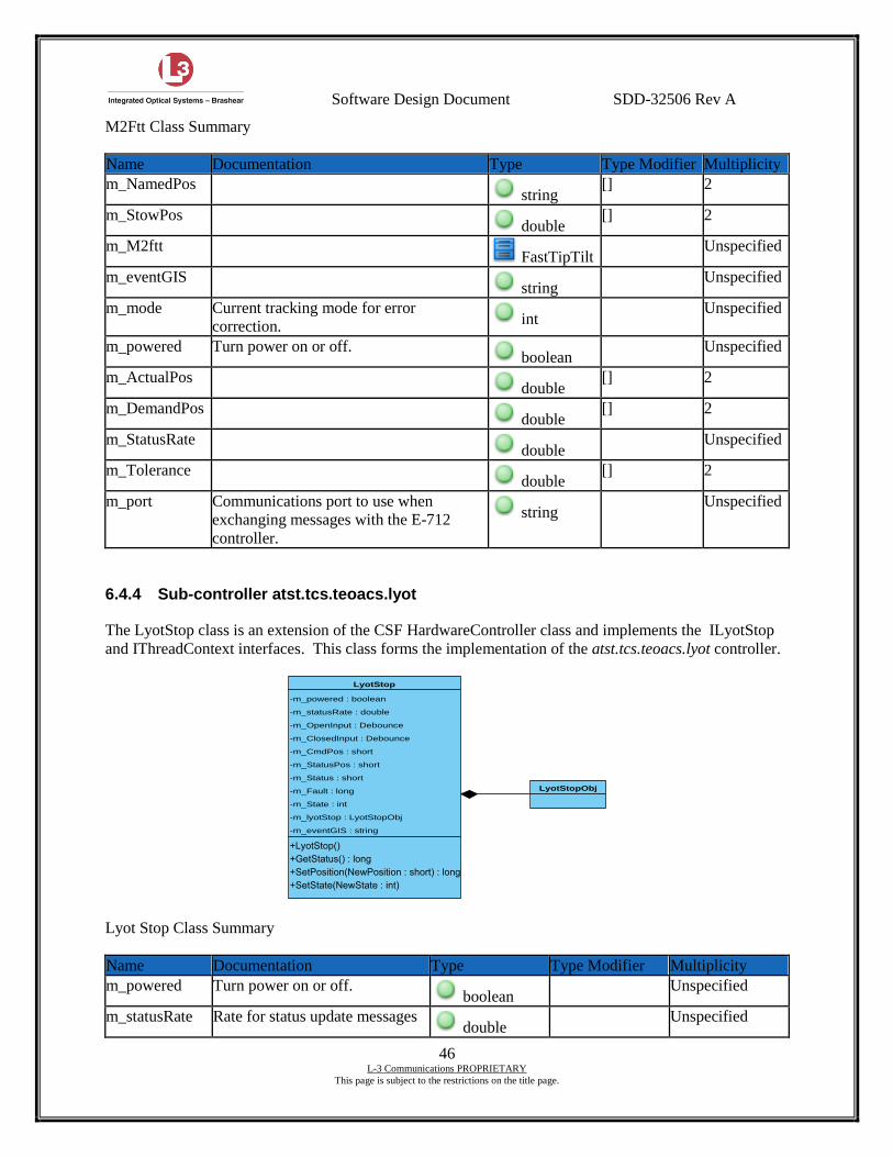
Software Design Document SDD-32506 Rev A
46 L-3 Communications PROPRIETARY
This page is subject to the restrictions on the title page.
M2Ftt Class Summary
Name Documentation Type Type Modifier Multiplicity
m_NamedPos string
[] 2
m_StowPos double
[] 2
m_M2ftt FastTipTilt
Unspecified
m_eventGIS string
Unspecified
m_mode Current tracking mode for error
correction. int
Unspecified
m_powered Turn power on or off. boolean
Unspecified
m_ActualPos double
[] 2
m_DemandPos double
[] 2
m_StatusRate double
Unspecified
m_Tolerance double
[] 2
m_port Communications port to use when
exchanging messages with the E-712
controller.
string Unspecified
6.4.4 Sub-controller atst.tcs.teoacs.lyot
The LyotStop class is an extension of the CSF HardwareController class and implements the ILyotStop
and IThreadContext interfaces. This class forms the implementation of the atst.tcs.teoacs.lyot controller.
Lyot Stop Class Summary
Name Documentation Type Type Modifier Multiplicity
m_powered Turn power on or off. boolean
Unspecified
m_statusRate Rate for status update messages double
Unspecified
LyotStopObj
-m_powered : boolean
-m_statusRate : double
-m_OpenInput : Debounce
-m_ClosedInput : Debounce
-m_CmdPos : short
-m_StatusPos : short
-m_Status : short
-m_Fault : long
-m_State : int
-m_lyotStop : LyotStopObj
-m_eventGIS : string
LyotStop
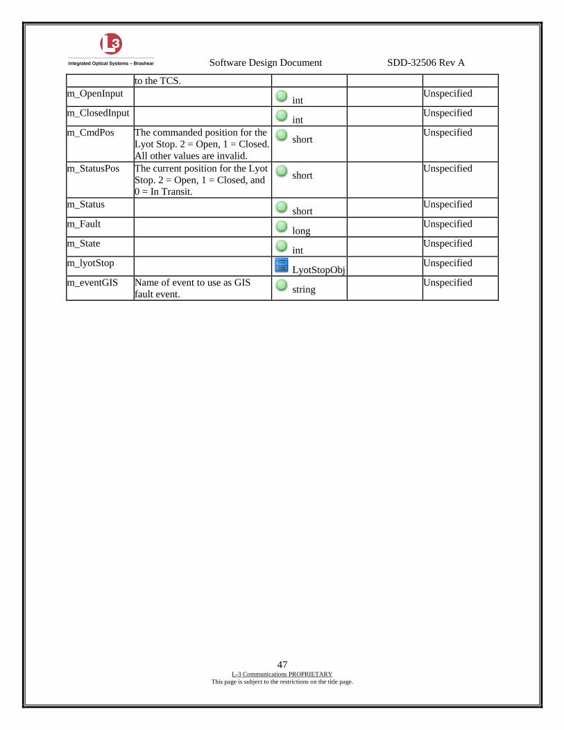
Software Design Document SDD-32506 Rev A
47 L-3 Communications PROPRIETARY
This page is subject to the restrictions on the title page.
to the TCS.
m_OpenInput int
Unspecified
m_ClosedInput int
Unspecified
m_CmdPos The commanded position for the
Lyot Stop. 2 = Open, 1 = Closed.
All other values are invalid.
short Unspecified
m_StatusPos The current position for the Lyot
Stop. 2 = Open, 1 = Closed, and
0 = In Transit.
short Unspecified
m_Status short
Unspecified
m_Fault long
Unspecified
m_State int
Unspecified
m_lyotStop LyotStopObj
Unspecified
m_eventGIS Name of event to use as GIS
fault event. string
Unspecified
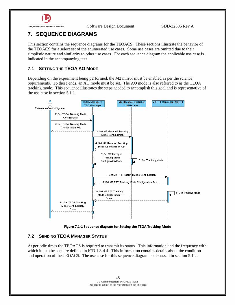
Software Design Document SDD-32506 Rev A
48 L-3 Communications PROPRIETARY
This page is subject to the restrictions on the title page.
7. SEQUENCE DIAGRAMS
This section contains the sequence diagrams for the TEOACS. These sections illustrate the behavior of
the TEOACS for a select set of the enumerated use cases. Some use cases are omitted due to their
simplistic nature and similarity to other use cases. For each sequence diagram the applicable use case is
indicated in the accompanying text.
7.1 SETTING THE TEOA AO MODE
Depending on the experiment being performed, the M2 mirror must be enabled as per the science
requirements. To these ends, an AO mode must be set. The AO mode is also referred to as the TEOA
tracking mode. This sequence illustrates the steps needed to accomplish this goal and is representative of
the use case in section 5.1.1.
Figure 7.1-1 Sequence diagram for Setting the TEOA Tracking Mode
7.2 SENDING TEOA MANAGER STATUS
At periodic times the TEOACS is required to transmit its status. This information and the frequency with
which it is to be sent are defined in ICD 1.3-4.4. This information contains details about the condition
and operation of the TEOACS. The use case for this sequence diagram is discussed in section 5.1.2.
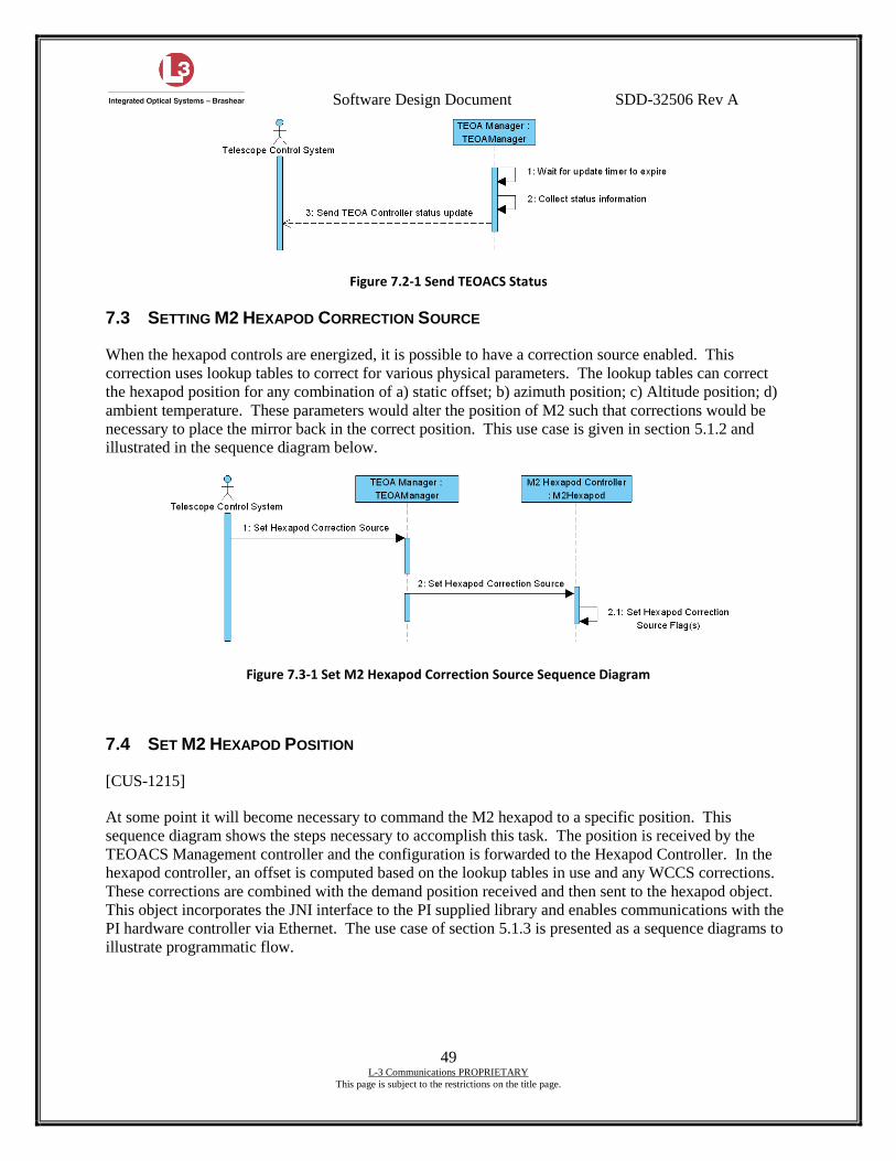
Software Design Document SDD-32506 Rev A
49 L-3 Communications PROPRIETARY
This page is subject to the restrictions on the title page.
Figure 7.2-1 Send TEOACS Status
7.3 SETTING M2 HEXAPOD CORRECTION SOURCE
When the hexapod controls are energized, it is possible to have a correction source enabled. This
correction uses lookup tables to correct for various physical parameters. The lookup tables can correct
the hexapod position for any combination of a) static offset; b) azimuth position; c) Altitude position; d)
ambient temperature. These parameters would alter the position of M2 such that corrections would be
necessary to place the mirror back in the correct position. This use case is given in section 5.1.2 and
illustrated in the sequence diagram below.
Figure 7.3-1 Set M2 Hexapod Correction Source Sequence Diagram
7.4 SET M2 HEXAPOD POSITION
[CUS-1215]
At some point it will become necessary to command the M2 hexapod to a specific position. This
sequence diagram shows the steps necessary to accomplish this task. The position is received by the
TEOACS Management controller and the configuration is forwarded to the Hexapod Controller. In the
hexapod controller, an offset is computed based on the lookup tables in use and any WCCS corrections.
These corrections are combined with the demand position received and then sent to the hexapod object.
This object incorporates the JNI interface to the PI supplied library and enables communications with the
PI hardware controller via Ethernet. The use case of section 5.1.3 is presented as a sequence diagrams to
illustrate programmatic flow.
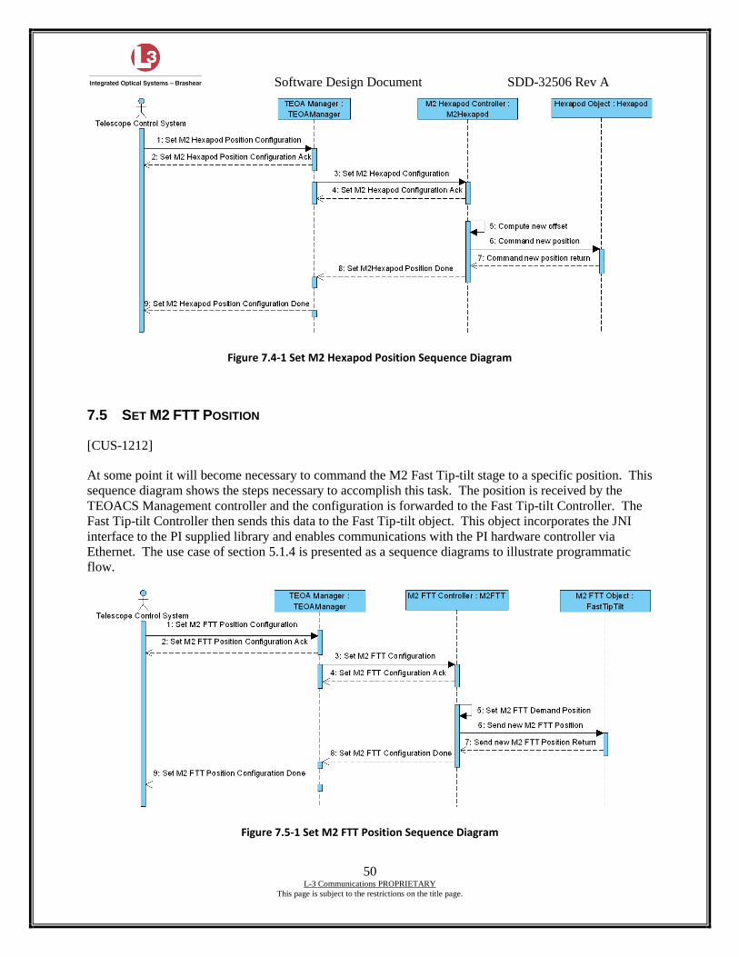
Software Design Document SDD-32506 Rev A
50 L-3 Communications PROPRIETARY
This page is subject to the restrictions on the title page.
Figure 7.4-1 Set M2 Hexapod Position Sequence Diagram
7.5 SET M2 FTT POSITION
[CUS-1212]
At some point it will become necessary to command the M2 Fast Tip-tilt stage to a specific position. This
sequence diagram shows the steps necessary to accomplish this task. The position is received by the
TEOACS Management controller and the configuration is forwarded to the Fast Tip-tilt Controller. The
Fast Tip-tilt Controller then sends this data to the Fast Tip-tilt object. This object incorporates the JNI
interface to the PI supplied library and enables communications with the PI hardware controller via
Ethernet. The use case of section 5.1.4 is presented as a sequence diagrams to illustrate programmatic
flow.
Figure 7.5-1 Set M2 FTT Position Sequence Diagram
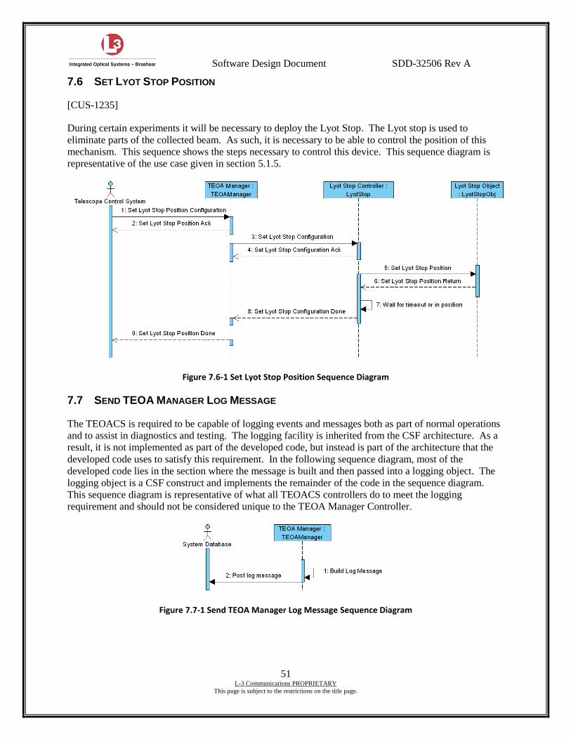
Software Design Document SDD-32506 Rev A
51 L-3 Communications PROPRIETARY
This page is subject to the restrictions on the title page.
7.6 SET LYOT STOP POSITION
[CUS-1235]
During certain experiments it will be necessary to deploy the Lyot Stop. The Lyot stop is used to
eliminate parts of the collected beam. As such, it is necessary to be able to control the position of this
mechanism. This sequence shows the steps necessary to control this device. This sequence diagram is
representative of the use case given in section 5.1.5.
Figure 7.6-1 Set Lyot Stop Position Sequence Diagram
7.7 SEND TEOA MANAGER LOG MESSAGE
The TEOACS is required to be capable of logging events and messages both as part of normal operations
and to assist in diagnostics and testing. The logging facility is inherited from the CSF architecture. As a
result, it is not implemented as part of the developed code, but instead is part of the architecture that the
developed code uses to satisfy this requirement. In the following sequence diagram, most of the
developed code lies in the section where the message is built and then passed into a logging object. The
logging object is a CSF construct and implements the remainder of the code in the sequence diagram.
This sequence diagram is representative of what all TEOACS controllers do to meet the logging
requirement and should not be considered unique to the TEOA Manager Controller.
Figure 7.7-1 Send TEOA Manager Log Message Sequence Diagram
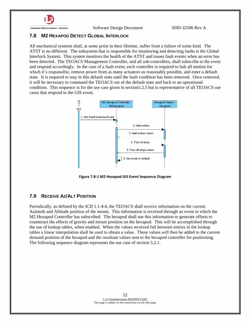
Software Design Document SDD-32506 Rev A
52 L-3 Communications PROPRIETARY
This page is subject to the restrictions on the title page.
7.8 M2 HEXAPOD DETECT GLOBAL INTERLOCK
All mechanical systems shall, at some point in their lifetime, suffer from a failure of some kind. The
ATST is no different. The subsystem that is responsible for monitoring and detecting faults is the Global
Interlock System. This system monitors the health of the ATST and issues fault events when an error has
been detected. The TEOACS Management Controller, and all sub-controllers, shall subscribe to ths event
and respond accordingly. In the case of a fault event, each controller is required to halt all motion for
which it’s responsible, remove power from as many actuators as reasonably possible, and enter a default
state. It is required to stay in this default state until the fault condition has been removed. Once removed,
it will be necessary to command the TEOACS out of the default state and back to an operational
condition. This sequence is for the use case given in section5.2.5 but is representative of all TEOACS use
cases that respond to the GIS event.
Figure 7.8-1 M2 Hexapod GIS Event Sequence Diagram
7.9 RECEIVE AZ/ALT POSITION
Periodically, as defined by the ICD 1.1-4.4, the TEOACS shall receive information on the current
Azimuth and Altitude position of the mount. This information is received through an event to which the
M2 Hexapod Controller has subscribed. The hexapod shall use this information to generate offsets to
counteract the effects of gravity and mount position on the hexapod. This will be accomplished through
the use of lookup tables, when enabled. When the values received fall between entries in the lookup
tables a linear interpolation shall be used to obtain a value. These values will then be added to the current
demand position of the hexapod and the resultant values sent to the hexapod controller for positioning.
The following sequence diagram represents the use case of section 5.2.1.
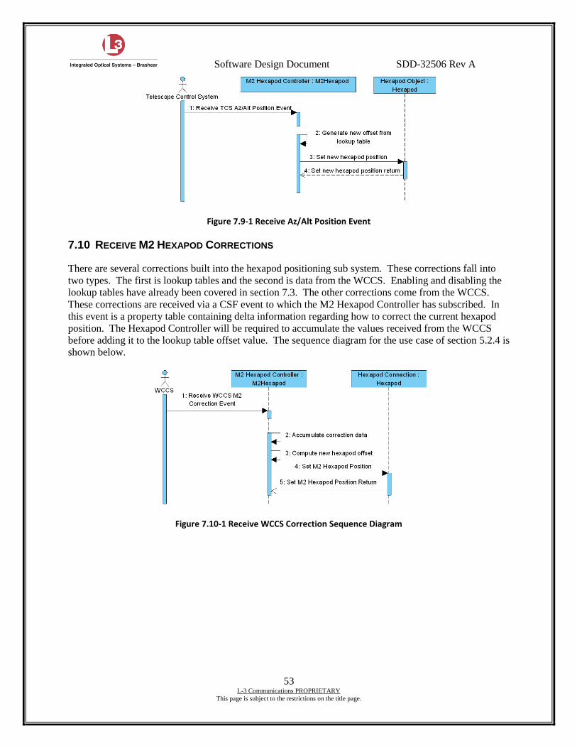
Software Design Document SDD-32506 Rev A
53 L-3 Communications PROPRIETARY
This page is subject to the restrictions on the title page.
Figure 7.9-1 Receive Az/Alt Position Event
7.10 RECEIVE M2 HEXAPOD CORRECTIONS
There are several corrections built into the hexapod positioning sub system. These corrections fall into
two types. The first is lookup tables and the second is data from the WCCS. Enabling and disabling the
lookup tables have already been covered in section 7.3. The other corrections come from the WCCS.
These corrections are received via a CSF event to which the M2 Hexapod Controller has subscribed. In
this event is a property table containing delta information regarding how to correct the current hexapod
position. The Hexapod Controller will be required to accumulate the values received from the WCCS
before adding it to the lookup table offset value. The sequence diagram for the use case of section 5.2.4 is
shown below.
Figure 7.10-1 Receive WCCS Correction Sequence Diagram
Software Design Document SDD-32506 Rev A
54 L-3 Communications PROPRIETARY
This page is subject to the restrictions on the title page.
8. TEOACS JAVA ENGINEERING SCREENS
[CUS-1301] [CUS-1303]
A requirement for the delivery of the TEOACS software is to provide an engineering GUI application.
This application is expected to run using the JES package provided as a part of the CSF architecture. This
application shall be capable of monitoring and manipulating the TEOA hardware. It is intended that any
operations that should be required of the TEOACS, the engineering GUI shall be capable of exercising.
In addition, it shall be able to view logging and health messages. It shall be a full participant of the CSF
network and communicate to the TEOACS using CSF in the same manner as any other subsystem in the
network.
The JES shall be capable of controlling the controller lifecycles (i.e. startup, shutdown, etc.) and
submitting configurations on which the controllers in the TEOACS will act. The engineering GUI shall
be capable of reading back properties of the TEOACS and displaying them.
The following images are intended to be preliminary designs of the screens that would be available
through the engineering GUI. These screens are not intended to be final designs, they should be
interpreted as representative of the information that would be present on the GUI screens.

Software Design Document SDD-32506 Rev A
55 L-3 Communications PROPRIETARY
This page is subject to the restrictions on the title page.
Figure 7.10-1 Management Controller JES
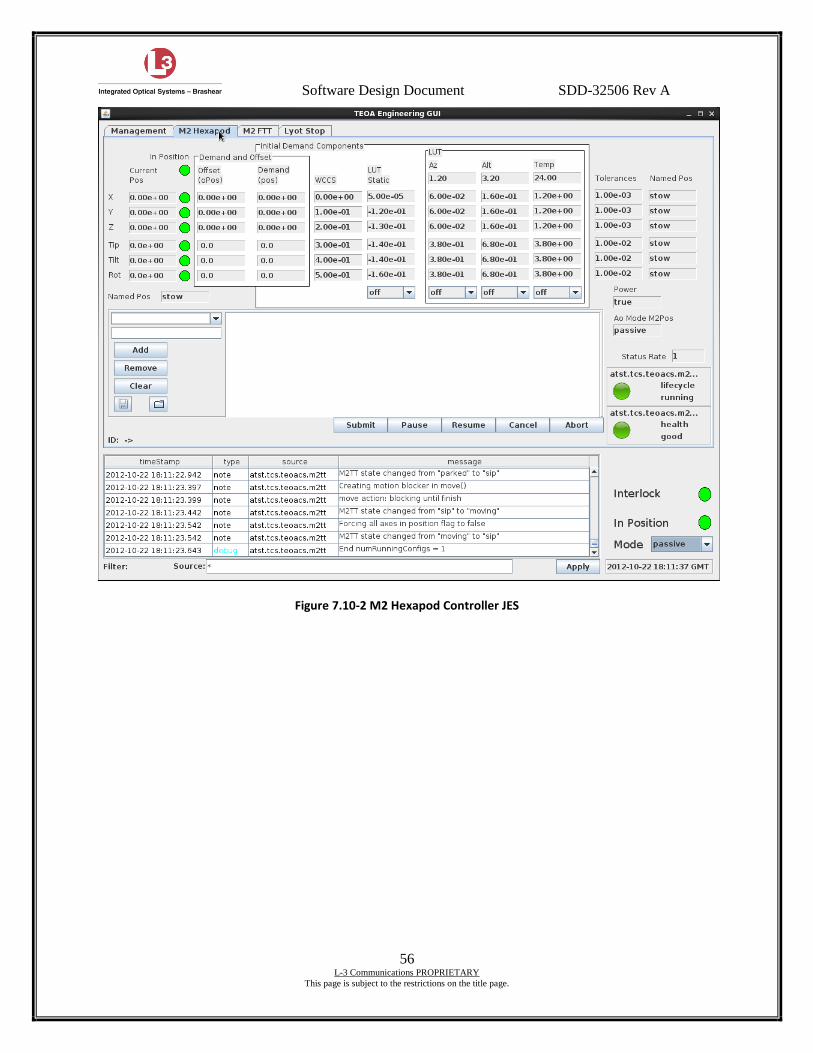
Software Design Document SDD-32506 Rev A
56 L-3 Communications PROPRIETARY
This page is subject to the restrictions on the title page.
Figure 7.10-2 M2 Hexapod Controller JES
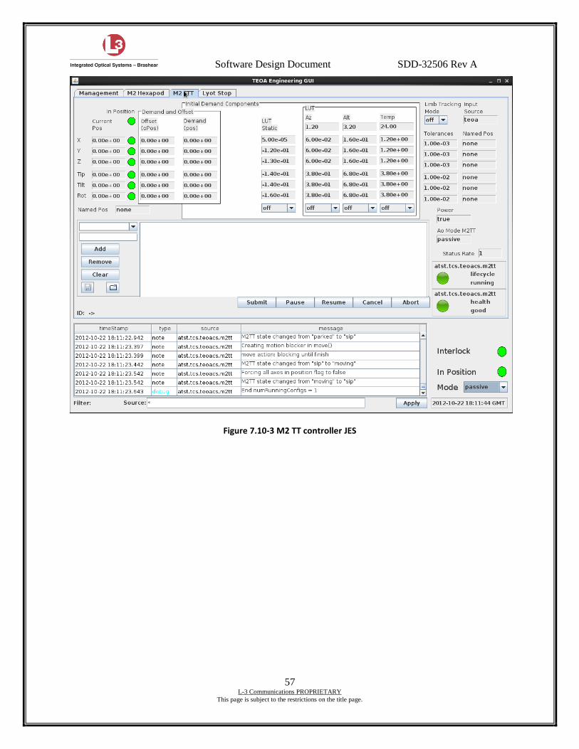
Software Design Document SDD-32506 Rev A
57 L-3 Communications PROPRIETARY
This page is subject to the restrictions on the title page.
Figure 7.10-3 M2 TT controller JES

Software Design Document SDD-32506 Rev A
58 L-3 Communications PROPRIETARY
This page is subject to the restrictions on the title page.
Figure 7.10-4 Lyot Stop JES
Software Design Document SDD-32506 Rev A
59 L-3 Communications PROPRIETARY
This page is subject to the restrictions on the title page.
9. SIMULATION
Simulation of the TEOACS is required to enable testing of the software interfaces and integration into the
overall observatory system. To support this simulation, the TEOA software and controllers will
implement a simulation mode that makes use of the CSF simulation facilities. All CSF controllers
support a simulation mode and hooks are provided in the architecture. The TEOACS will be no different
and shall make use of these features to implement the simulation of the TEOA hardware.
Simulation of the hardware components in the system will be limited to the status feedback positions of
mechanical actuators to immediately match the demand positions. There shall be no intent for the
motions to actually mimic real-life quality of motion (i.e. s-curves on actuator motion).
Since simulation will be implemented in, and through, CSF constructs, there will be no requirement for
virtualization of any hardware controllers or use of communications libraries in simulation.
9.1 TCS SIMULATION REQUIRED BY THE TEOACS
The TEOACS subscribes to the TCS trajectory event published by the TCS. This event contains the
current Az/Alt position and is used by the TEOACS to generate corrections for the hexapod. To fully test
this function of the TEOACS, the JES will be required to simulate this event. One of the tabs on the JES
GUI allows the user to enter a start and stop position as well as a velocity. Upon executing this trajectory,
a stream of events will be generated to which the TEOACS can subscribe. In this manner, the TEOACS
handling of this event can be tested.
9.2 GIS SIMULATION REQUIRED BY THE TEOACS
The TEOACS subscribes to the GIS fault event. To fully test the TEOACS response to this event, the
JES will have to simulate the GIS fault events. To this end, the JES has an Event menu selection which
will enable the user to selectively send the simulated GIS fault and fault cleared events. This will enable
testing of the TEOACS response and handling of these events.

Software Design Document SDD-32506 Rev A
60 L-3 Communications PROPRIETARY
This page is subject to the restrictions on the title page.
10. TESTING
The TEOA Acceptance Test Procedure shall be written to ensure that the TEOACS meets the
requirements as specified in the TEOA specifications. Testing shall be automated to the extent possible
through the use of scripts or other repeatable methods. These scripts shall also be included as part of the
ATP document.
10.1 BUILT-IN TESTS
As part of the internal diagnostics resident in the TEOACS, several built-in tests will be implemented.
These tests are expected to run periodically as part of the TEOACS health checks.
10.1.1 M2 Hexapod
This is a continual test to determine if the TEOACS is able to communicate with the M-850 controller.
This communications link is key to being able to properly position the M2 optic.
10.1.2 M2 Fast TipTilt
This is a continual test to determine if the TEOACS is able to communicate with the E-710 controller.
This communications link is key to being able to properly position the M2 optic.
10.1.3 Lyot Stop
A continual check will be made of the position feedback sensors. This test is designed to detect problems
where both sensors are indicating “In Position”, a case that physically cannot occur.
10.1.4 TEOA Manager
The TEOA Manager will periodically check to establish that all of the controllers of the TEOACS have
actually been loaded and are running. If any controllers are not running, the TEOA Manager will indicate
this status.
10.1.5 Tests executed at startup
Any tests that are executed at startup, and fail, will cause the health of the associated controller to change
to ILL.
10.1.6 PLC
Since the PLC is implemented using PLC logic, the testing scenarios are a little different. In the case of
the PLC, periodic checks shall be made of the temperature sensors to validate the integrity of the sensors
(open or good), as well as validating the communications link with the M2 chiller and blower.
Software Design Document SDD-32506 Rev A
61 L-3 Communications PROPRIETARY
This page is subject to the restrictions on the title page.
11. THERMAL/SAFETY PLC
[CUS-1269]
Thermal management of M2 has been segregated into a PLC for safety reasons. To complement the
safety functions, the PLC also controls the movement of the heat stop shutter and manages the interface to
the GIS through the LIC. The PLC is separate and distinct from the TEOA Control System described in
the previous sections. The two systems do not communicate with each other and do not share any data.
The PLC will be implemented using standard Allen-Bradley® ControlLogix® compatible components.
11.1 THERMAL/SAFETY PLC AND FCS INTEGRATION
The PLC will communicate through the FCS. By proper configuration of the PLC and publishing tag
information, the FCS will be able to communicate with the TEOA PLC and control its operation. Further
information regarding the interface between the PLC and the FCS will be needed from AURA.
11.2 HEAT STOP THERMAL CONTROL
There is no thermal control, per se, of the heat stop. Upon startup, the coolant will be running at full flow.
No software is required for this other than monitoring the temperatures. The temperatures will be
monitored by the heat stop shutter software as part of the safety features.
11.3 HEAT STOP SHUTTER CONTROL
The heat stop shutter is controllable through the discrete input present on the GIS LIC. This input will be
honored only when there are no faults present and the PLC has been commanded to RUN mode via the
FCS. Regardless of the state of the input line, once a fault is sensed from the TEOA sensors, or the GIS
fault line is asserted, the shutter will be closed. This software module will read the temperatures and
coolant flow characteristics of both the M2 cooling system and the heat stop. These values will be used to
determine out of limit conditions that will then trigger faults and the closure of the heat stop shutter. The
faults outputs that are required to be supported are defined in ICD 1.3-4.5 TEOA to GIS – Rev A.
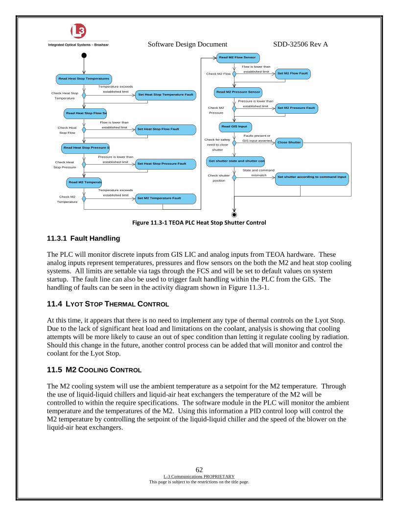
Software Design Document SDD-32506 Rev A
62 L-3 Communications PROPRIETARY
This page is subject to the restrictions on the title page.
Figure 11.3-1 TEOA PLC Heat Stop Shutter Control
11.3.1 Fault Handling
The PLC will monitor discrete inputs from GIS LIC and analog inputs from TEOA hardware. These
analog inputs represent temperatures, pressures and flow sensors on the both the M2 and heat stop cooling
systems. All limits are settable via tags through the FCS and will be set to default values on system
startup. The fault line can also be used to trigger fault handling within the PLC from the GIS. The
handling of faults can be seen in the activity diagram shown in Figure 11.3-1.
11.4 LYOT STOP THERMAL CONTROL
At this time, it appears that there is no need to implement any type of thermal controls on the Lyot Stop.
Due to the lack of significant heat load and limitations on the coolant, analysis is showing that cooling
attempts will be more likely to cause an out of spec condition than letting it regulate cooling by radiation.
Should this change in the future, another control process can be added that will monitor and control the
coolant for the Lyot Stop.
11.5 M2 COOLING CONTROL
The M2 cooling system will use the ambient temperature as a setpoint for the M2 temperature. Through
the use of liquid-liquid chillers and liquid-air heat exchangers the temperature of the M2 will be
controlled to within the require specifications. The software module in the PLC will monitor the ambient
temperature and the temperatures of the M2. Using this information a PID control loop will control the
M2 temperature by controlling the setpoint of the liquid-liquid chiller and the speed of the blower on the
liquid-air heat exchangers.
Read Heat Stop Temperatures
Close Shutter
Read Heat Stop Flow Sensor
Read Heat Stop Pressure Sensor
Set Heat Stop Temperature Fault
Set Heat Stop Flow Fault
Set Heat Stop Pressure Fault
Read M2 Temperature
Read M2 Flow Sensor
Read M2 Pressure Sensor
Set M2 Temperature Fault
Set M2 Flow Fault
Set M2 Pressure Fault
Read GIS Input
Get shutter state and shutter command
Set shutter according to command inputCheck shutter
position
Check for safety
need to close
shutter
Check M2
Pressure
Check M2 Flow
Check M2
Temperature
Check Heat
Stop Pressure
Check Heat
Stop Flow
Check Heat Stop
Temperature
State and command
mismatch
Faults present or
GIS input asserted
Pressure is lower than
established limit
Flow is lower than
established limit
Temperature exceeds
established limit
Pressure is lower than
established limit
Flow is lower than
established limit
Temperature exceeds
established limit
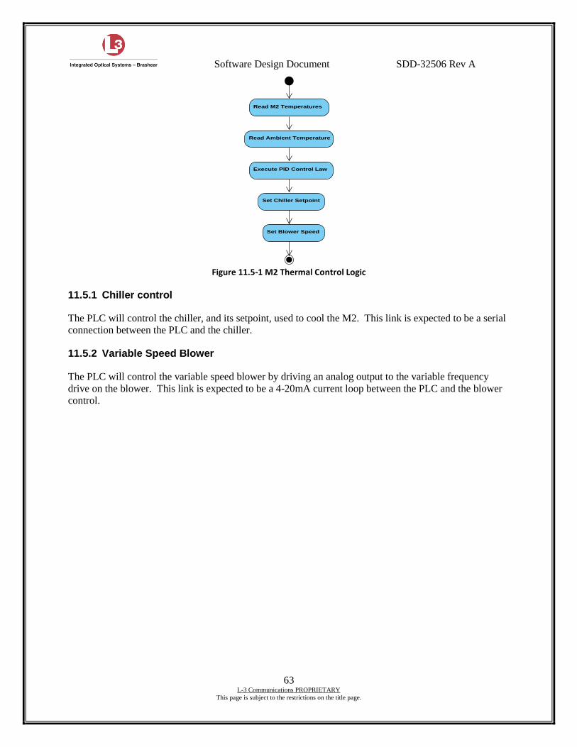
Software Design Document SDD-32506 Rev A
63 L-3 Communications PROPRIETARY
This page is subject to the restrictions on the title page.
Figure 11.5-1 M2 Thermal Control Logic
11.5.1 Chiller control
The PLC will control the chiller, and its setpoint, used to cool the M2. This link is expected to be a serial
connection between the PLC and the chiller.
11.5.2 Variable Speed Blower
The PLC will control the variable speed blower by driving an analog output to the variable frequency
drive on the blower. This link is expected to be a 4-20mA current loop between the PLC and the blower
control.
Read M2 Temperatures
Read Ambient Temperature
Execute PID Control Law
Set Chiller Setpoint
Set Blower Speed
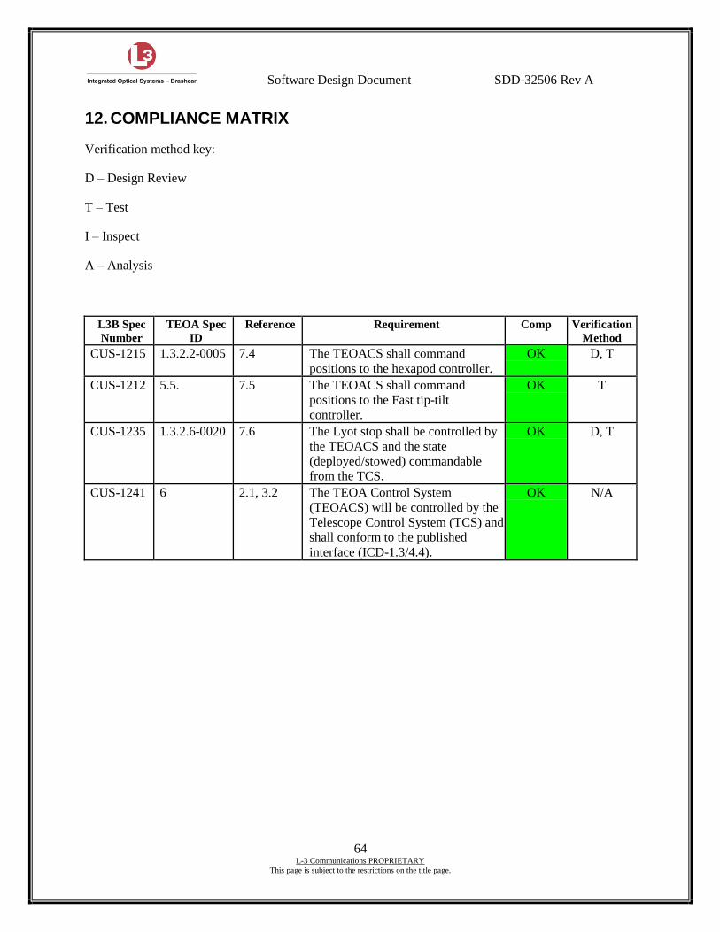
Software Design Document SDD-32506 Rev A
64 L-3 Communications PROPRIETARY
This page is subject to the restrictions on the title page.
12. COMPLIANCE MATRIX
Verification method key:
D – Design Review
T – Test
I – Inspect
A – Analysis
L3B Spec
Number
TEOA Spec
ID
Reference Requirement Comp Verification
Method
CUS-1215 1.3.2.2-0005 7.4 The TEOACS shall command
positions to the hexapod controller.
OK D, T
CUS-1212 5.5. 7.5 The TEOACS shall command
positions to the Fast tip-tilt
controller.
OK T
CUS-1235 1.3.2.6-0020 7.6 The Lyot stop shall be controlled by
the TEOACS and the state
(deployed/stowed) commandable
from the TCS.
OK D, T
CUS-1241 6 2.1, 3.2 The TEOA Control System
(TEOACS) will be controlled by the
Telescope Control System (TCS) and
shall conform to the published
interface (ICD-1.3/4.4).
OK N/A
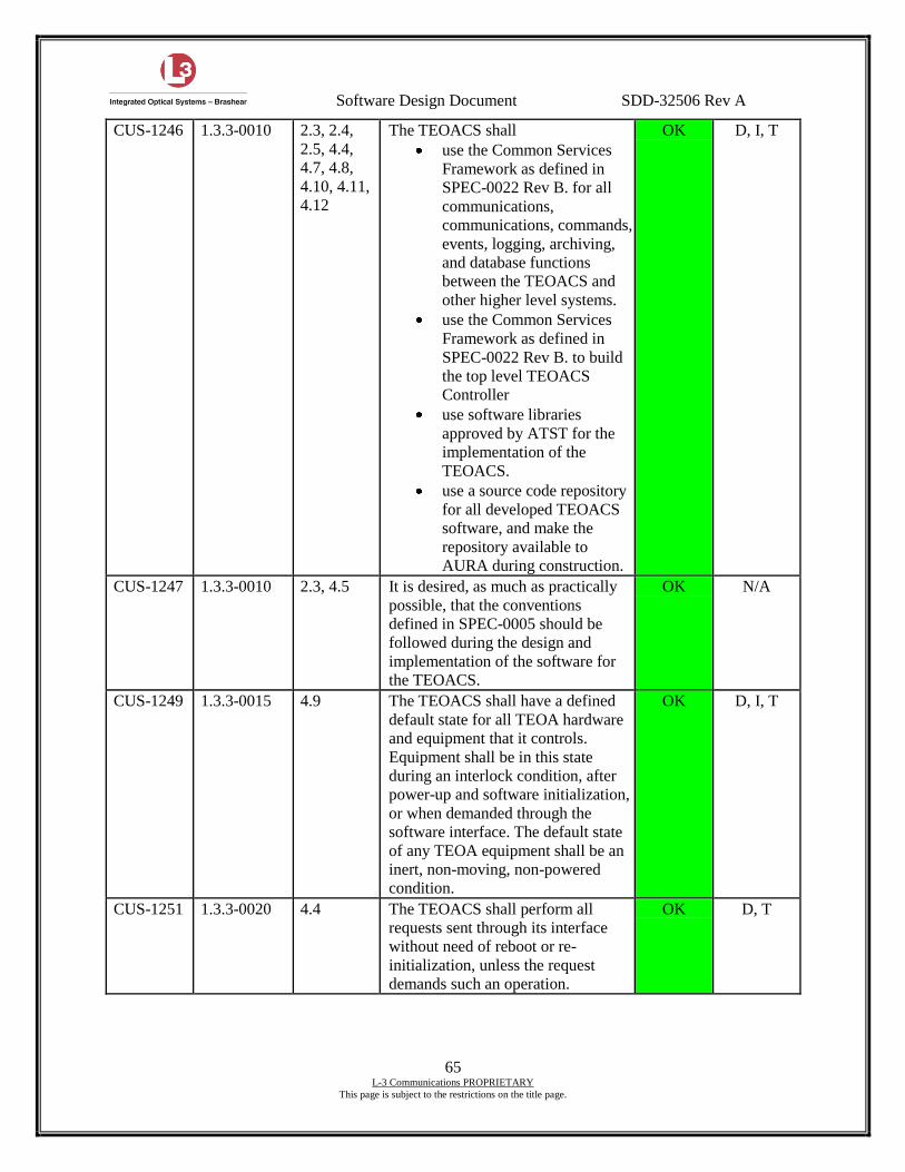
Software Design Document SDD-32506 Rev A
65 L-3 Communications PROPRIETARY
This page is subject to the restrictions on the title page.
CUS-1246 1.3.3-0010 2.3, 2.4,
2.5, 4.4,
4.7, 4.8,
4.10, 4.11,
4.12
The TEOACS shall
use the Common Services
Framework as defined in
SPEC-0022 Rev B. for all
communications,
communications, commands,
events, logging, archiving,
and database functions
between the TEOACS and
other higher level systems.
use the Common Services
Framework as defined in
SPEC-0022 Rev B. to build
the top level TEOACS
Controller
use software libraries
approved by ATST for the
implementation of the
TEOACS.
use a source code repository
for all developed TEOACS
software, and make the
repository available to
AURA during construction.
OK D, I, T
CUS-1247 1.3.3-0010 2.3, 4.5 It is desired, as much as practically
possible, that the conventions
defined in SPEC-0005 should be
followed during the design and
implementation of the software for
the TEOACS.
OK N/A
CUS-1249 1.3.3-0015 4.9 The TEOACS shall have a defined
default state for all TEOA hardware
and equipment that it controls.
Equipment shall be in this state
during an interlock condition, after
power-up and software initialization,
or when demanded through the
software interface. The default state
of any TEOA equipment shall be an
inert, non-moving, non-powered
condition.
OK D, I, T
CUS-1251 1.3.3-0020 4.4 The TEOACS shall perform all
requests sent through its interface
without need of reboot or re-
initialization, unless the request
demands such an operation.
OK D, T
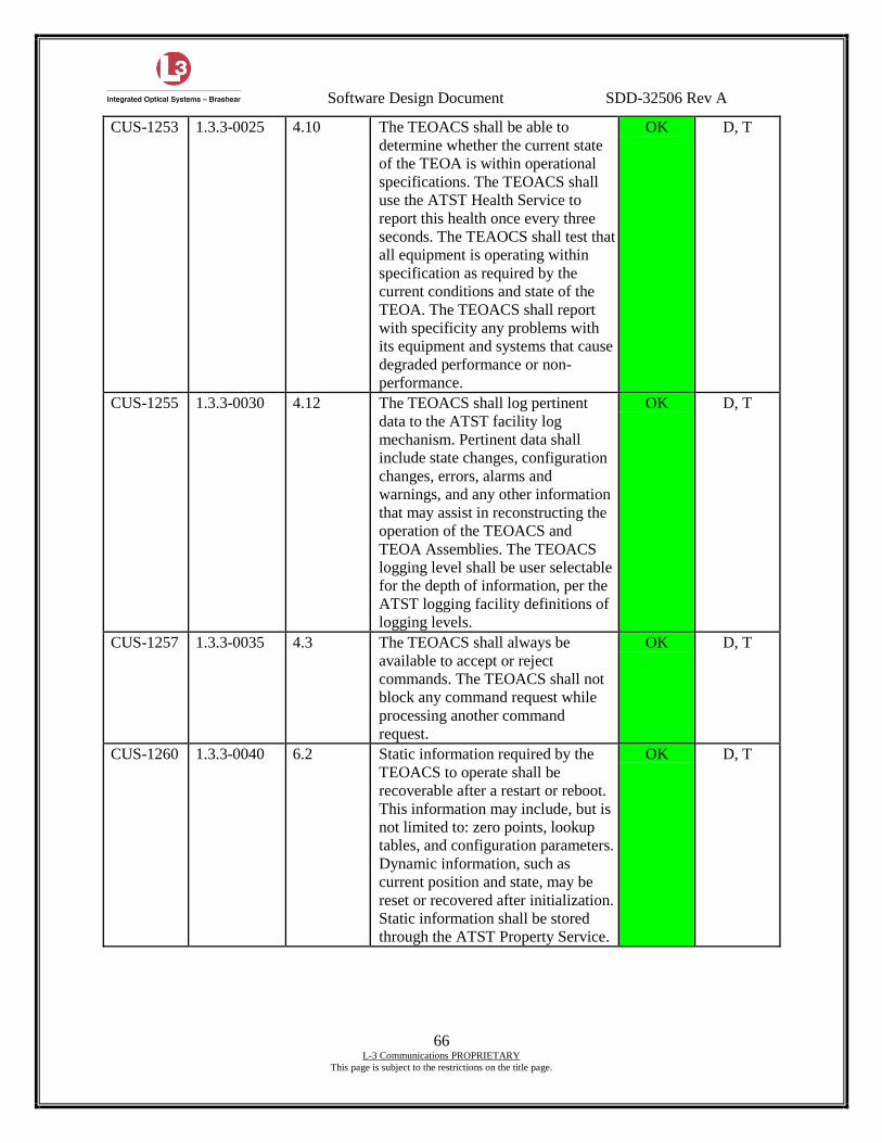
Software Design Document SDD-32506 Rev A
66 L-3 Communications PROPRIETARY
This page is subject to the restrictions on the title page.
CUS-1253 1.3.3-0025 4.10 The TEOACS shall be able to
determine whether the current state
of the TEOA is within operational
specifications. The TEOACS shall
use the ATST Health Service to
report this health once every three
seconds. The TEAOCS shall test that
all equipment is operating within
specification as required by the
current conditions and state of the
TEOA. The TEOACS shall report
with specificity any problems with
its equipment and systems that cause
degraded performance or non-
performance.
OK D, T
CUS-1255 1.3.3-0030 4.12 The TEOACS shall log pertinent
data to the ATST facility log
mechanism. Pertinent data shall
include state changes, configuration
changes, errors, alarms and
warnings, and any other information
that may assist in reconstructing the
operation of the TEOACS and
TEOA Assemblies. The TEOACS
logging level shall be user selectable
for the depth of information, per the
ATST logging facility definitions of
logging levels.
OK D, T
CUS-1257 1.3.3-0035 4.3 The TEOACS shall always be
available to accept or reject
commands. The TEOACS shall not
block any command request while
processing another command
request.
OK D, T
CUS-1260 1.3.3-0040 6.2 Static information required by the
TEOACS to operate shall be
recoverable after a restart or reboot.
This information may include, but is
not limited to: zero points, lookup
tables, and configuration parameters.
Dynamic information, such as
current position and state, may be
reset or recovered after initialization.
Static information shall be stored
through the ATST Property Service.
OK D, T
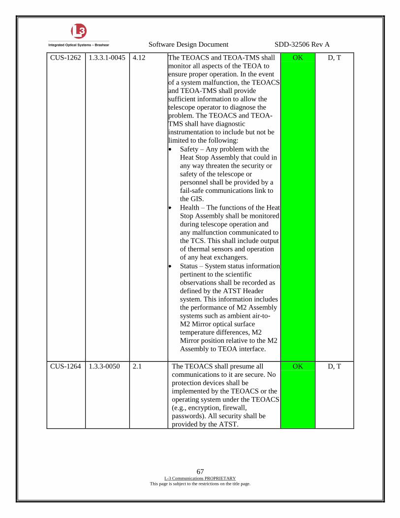
Software Design Document SDD-32506 Rev A
67 L-3 Communications PROPRIETARY
This page is subject to the restrictions on the title page.
CUS-1262 1.3.3.1-0045 4.12 The TEOACS and TEOA-TMS shall
monitor all aspects of the TEOA to
ensure proper operation. In the event
of a system malfunction, the TEOACS
and TEOA-TMS shall provide
sufficient information to allow the
telescope operator to diagnose the
problem. The TEOACS and TEOA-
TMS shall have diagnostic
instrumentation to include but not be
limited to the following:
Safety – Any problem with the
Heat Stop Assembly that could in
any way threaten the security or
safety of the telescope or
personnel shall be provided by a
fail-safe communications link to
the GIS.
Health – The functions of the Heat
Stop Assembly shall be monitored
during telescope operation and
any malfunction communicated to
the TCS. This shall include output
of thermal sensors and operation
of any heat exchangers.
Status – System status information
pertinent to the scientific
observations shall be recorded as
defined by the ATST Header
system. This information includes
the performance of M2 Assembly
systems such as ambient air-to-
M2 Mirror optical surface
temperature differences, M2
Mirror position relative to the M2
Assembly to TEOA interface.
OK D, T
CUS-1264 1.3.3-0050 2.1 The TEOACS shall presume all
communications to it are secure. No
protection devices shall be
implemented by the TEOACS or the
operating system under the TEOACS
(e.g., encryption, firewall,
passwords). All security shall be
provided by the ATST.
OK D, T
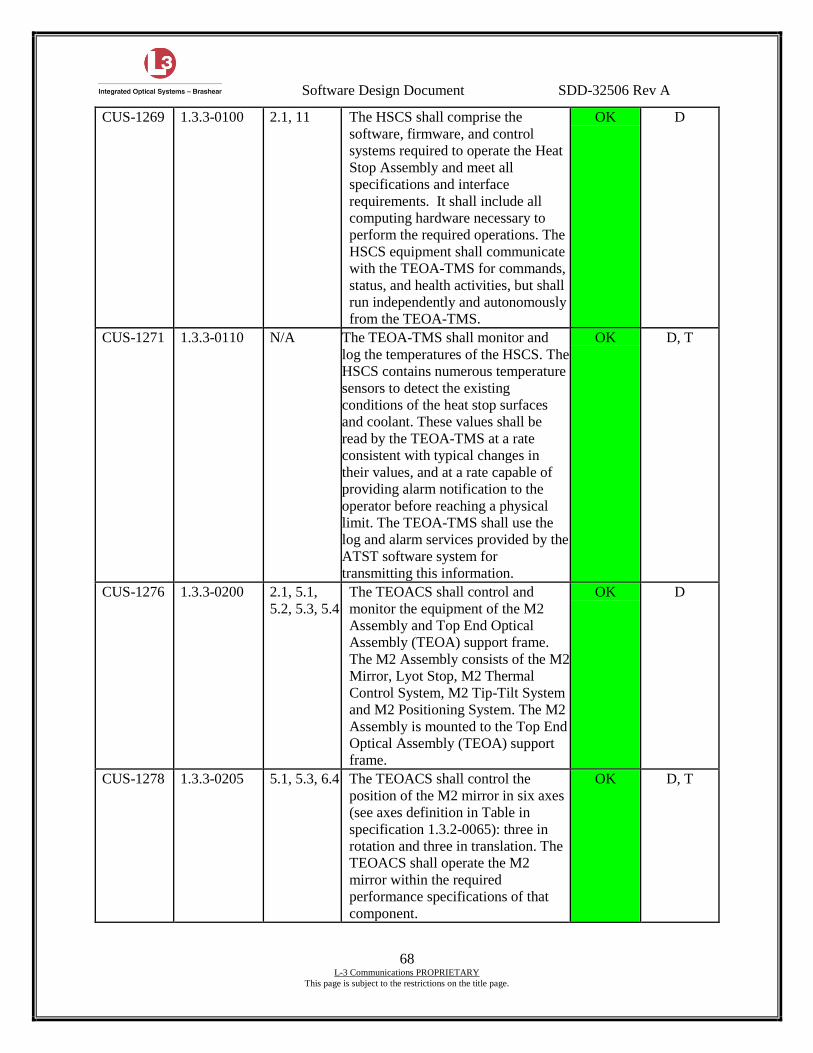
Software Design Document SDD-32506 Rev A
68 L-3 Communications PROPRIETARY
This page is subject to the restrictions on the title page.
CUS-1269 1.3.3-0100 2.1, 11 The HSCS shall comprise the
software, firmware, and control
systems required to operate the Heat
Stop Assembly and meet all
specifications and interface
requirements. It shall include all
computing hardware necessary to
perform the required operations. The
HSCS equipment shall communicate
with the TEOA-TMS for commands,
status, and health activities, but shall
run independently and autonomously
from the TEOA-TMS.
OK D
CUS-1271 1.3.3-0110 N/A The TEOA-TMS shall monitor and
log the temperatures of the HSCS. The
HSCS contains numerous temperature
sensors to detect the existing
conditions of the heat stop surfaces
and coolant. These values shall be
read by the TEOA-TMS at a rate
consistent with typical changes in
their values, and at a rate capable of
providing alarm notification to the
operator before reaching a physical
limit. The TEOA-TMS shall use the
log and alarm services provided by the
ATST software system for
transmitting this information.
OK D, T
CUS-1276 1.3.3-0200 2.1, 5.1,
5.2, 5.3, 5.4
The TEOACS shall control and
monitor the equipment of the M2
Assembly and Top End Optical
Assembly (TEOA) support frame.
The M2 Assembly consists of the M2
Mirror, Lyot Stop, M2 Thermal
Control System, M2 Tip-Tilt System
and M2 Positioning System. The M2
Assembly is mounted to the Top End
Optical Assembly (TEOA) support
frame.
OK D
CUS-1278 1.3.3-0205 5.1, 5.3, 6.4 The TEOACS shall control the
position of the M2 mirror in six axes
(see axes definition in Table in
specification 1.3.2-0065): three in
rotation and three in translation. The
TEOACS shall operate the M2
mirror within the required
performance specifications of that
component.
OK D, T
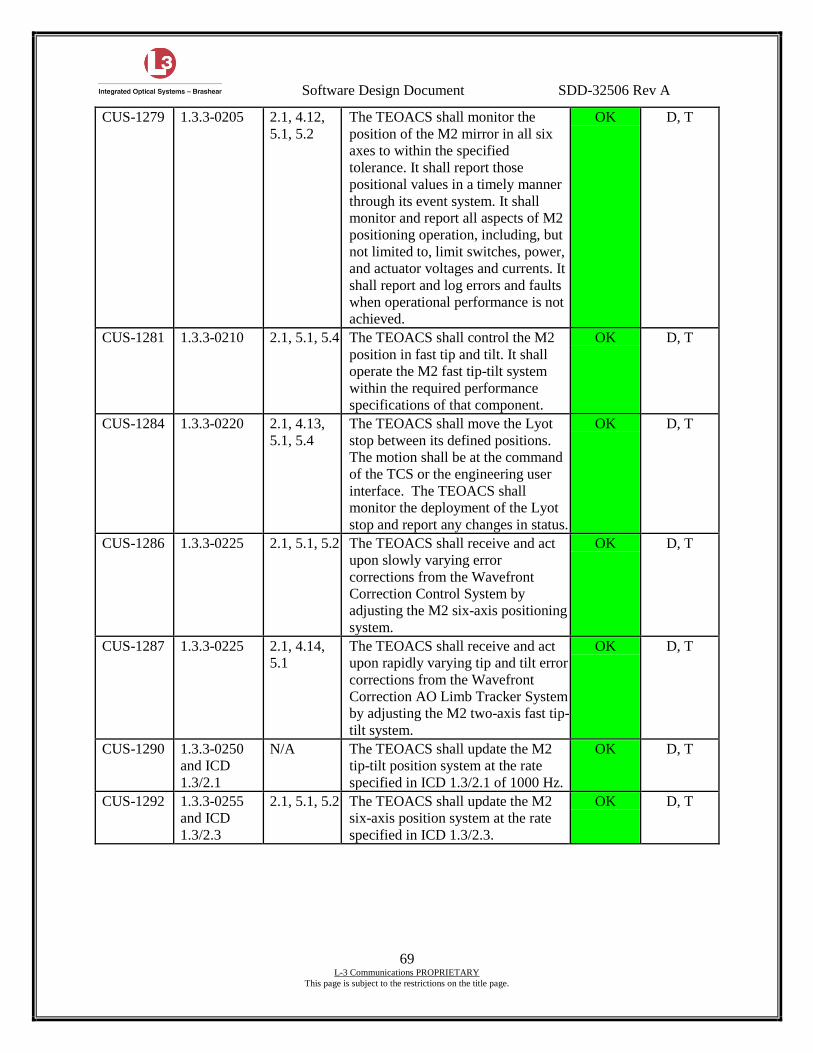
Software Design Document SDD-32506 Rev A
69 L-3 Communications PROPRIETARY
This page is subject to the restrictions on the title page.
CUS-1279 1.3.3-0205 2.1, 4.12,
5.1, 5.2
The TEOACS shall monitor the
position of the M2 mirror in all six
axes to within the specified
tolerance. It shall report those
positional values in a timely manner
through its event system. It shall
monitor and report all aspects of M2
positioning operation, including, but
not limited to, limit switches, power,
and actuator voltages and currents. It
shall report and log errors and faults
when operational performance is not
achieved.
OK D, T
CUS-1281 1.3.3-0210 2.1, 5.1, 5.4 The TEOACS shall control the M2
position in fast tip and tilt. It shall
operate the M2 fast tip-tilt system
within the required performance
specifications of that component.
OK D, T
CUS-1284 1.3.3-0220 2.1, 4.13,
5.1, 5.4
The TEOACS shall move the Lyot
stop between its defined positions.
The motion shall be at the command
of the TCS or the engineering user
interface. The TEOACS shall
monitor the deployment of the Lyot
stop and report any changes in status.
OK D, T
CUS-1286 1.3.3-0225 2.1, 5.1, 5.2 The TEOACS shall receive and act
upon slowly varying error
corrections from the Wavefront
Correction Control System by
adjusting the M2 six-axis positioning
system.
OK D, T
CUS-1287 1.3.3-0225 2.1, 4.14,
5.1
The TEOACS shall receive and act
upon rapidly varying tip and tilt error
corrections from the Wavefront
Correction AO Limb Tracker System
by adjusting the M2 two-axis fast tip-
tilt system.
OK D, T
CUS-1290 1.3.3-0250
and ICD
1.3/2.1
N/A The TEOACS shall update the M2
tip-tilt position system at the rate
specified in ICD 1.3/2.1 of 1000 Hz.
OK D, T
CUS-1292 1.3.3-0255
and ICD
1.3/2.3
2.1, 5.1, 5.2 The TEOACS shall update the M2
six-axis position system at the rate
specified in ICD 1.3/2.3.
OK D, T
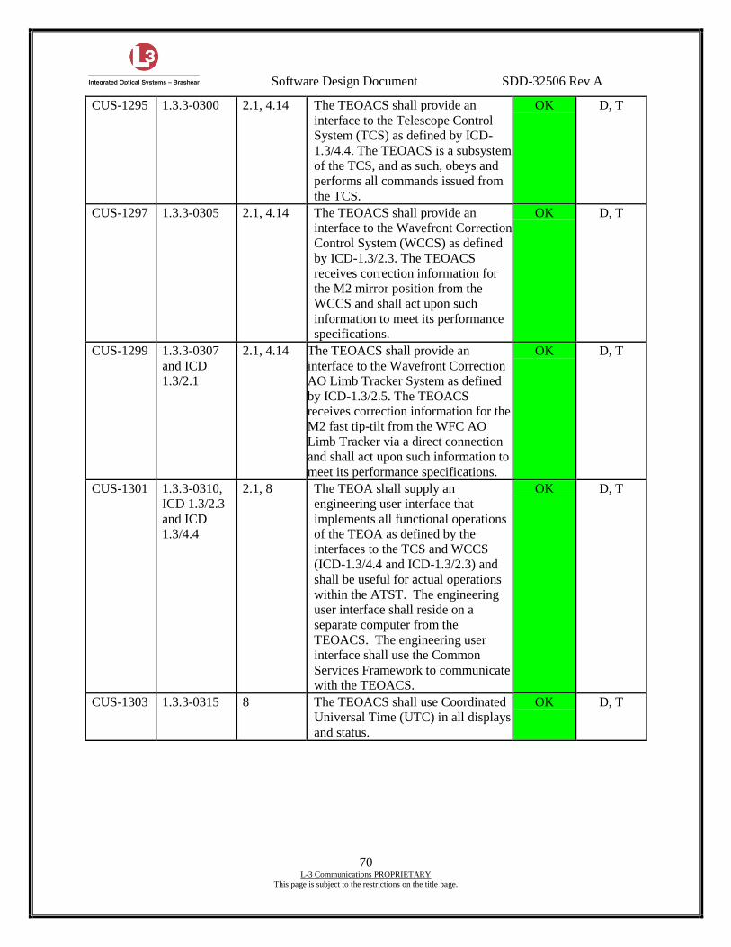
Software Design Document SDD-32506 Rev A
70 L-3 Communications PROPRIETARY
This page is subject to the restrictions on the title page.
CUS-1295 1.3.3-0300 2.1, 4.14 The TEOACS shall provide an
interface to the Telescope Control
System (TCS) as defined by ICD-
1.3/4.4. The TEOACS is a subsystem
of the TCS, and as such, obeys and
performs all commands issued from
the TCS.
OK D, T
CUS-1297 1.3.3-0305 2.1, 4.14 The TEOACS shall provide an
interface to the Wavefront Correction
Control System (WCCS) as defined
by ICD-1.3/2.3. The TEOACS
receives correction information for
the M2 mirror position from the
WCCS and shall act upon such
information to meet its performance
specifications.
OK D, T
CUS-1299 1.3.3-0307
and ICD
1.3/2.1
2.1, 4.14 The TEOACS shall provide an
interface to the Wavefront Correction
AO Limb Tracker System as defined
by ICD-1.3/2.5. The TEOACS
receives correction information for the
M2 fast tip-tilt from the WFC AO
Limb Tracker via a direct connection
and shall act upon such information to
meet its performance specifications.
OK D, T
CUS-1301 1.3.3-0310,
ICD 1.3/2.3
and ICD
1.3/4.4
2.1, 8 The TEOA shall supply an
engineering user interface that
implements all functional operations
of the TEOA as defined by the
interfaces to the TCS and WCCS
(ICD-1.3/4.4 and ICD-1.3/2.3) and
shall be useful for actual operations
within the ATST. The engineering
user interface shall reside on a
separate computer from the
TEOACS. The engineering user
interface shall use the Common
Services Framework to communicate
with the TEOACS.
OK D, T
CUS-1303 1.3.3-0315 8 The TEOACS shall use Coordinated
Universal Time (UTC) in all displays
and status.
OK D, T
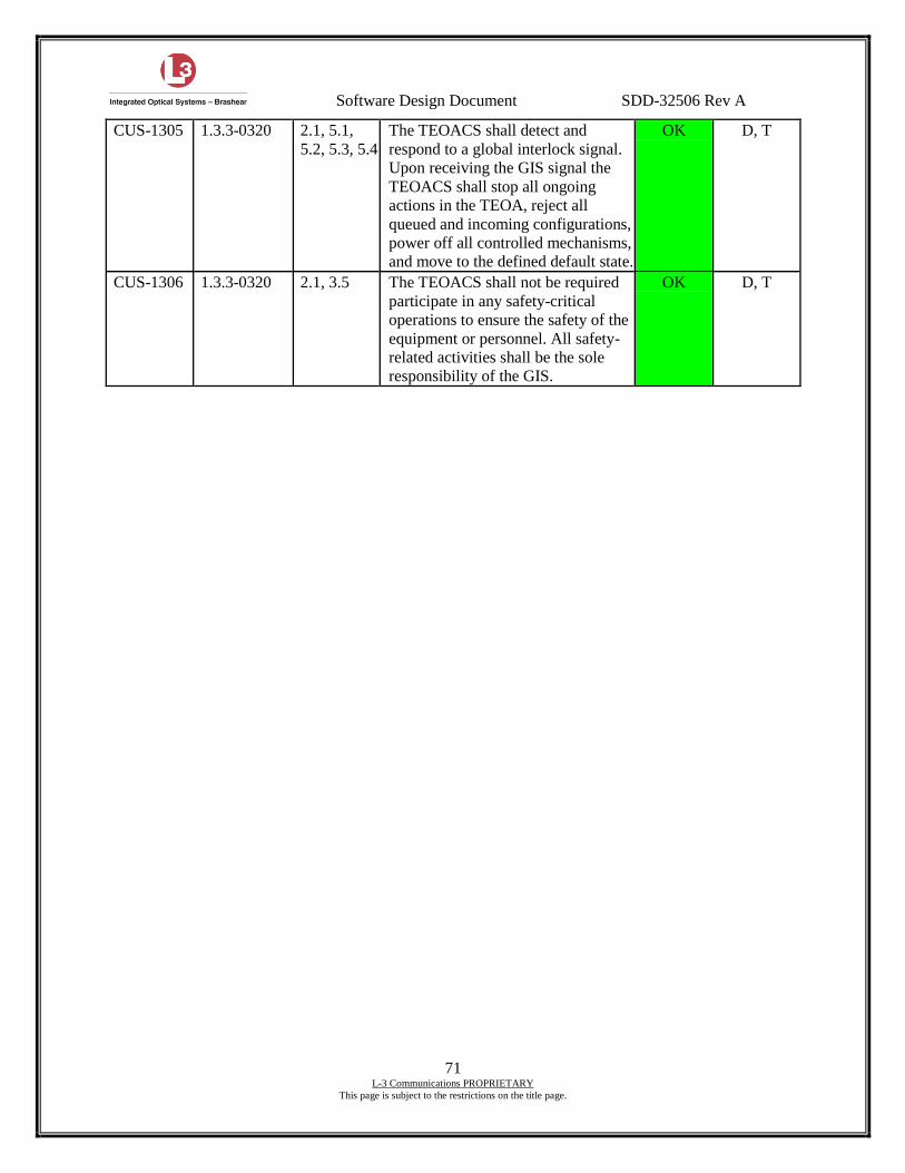
Software Design Document SDD-32506 Rev A
71 L-3 Communications PROPRIETARY
This page is subject to the restrictions on the title page.
CUS-1305 1.3.3-0320 2.1, 5.1,
5.2, 5.3, 5.4
The TEOACS shall detect and
respond to a global interlock signal.
Upon receiving the GIS signal the
TEOACS shall stop all ongoing
actions in the TEOA, reject all
queued and incoming configurations,
power off all controlled mechanisms,
and move to the defined default state.
OK D, T
CUS-1306 1.3.3-0320 2.1, 3.5 The TEOACS shall not be required
participate in any safety-critical
operations to ensure the safety of the
equipment or personnel. All safety-
related activities shall be the sole
responsibility of the GIS.
OK D, T
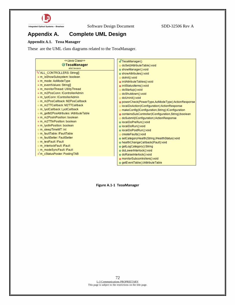
Software Design Document SDD-32506 Rev A
72 L-3 Communications PROPRIETARY
This page is subject to the restrictions on the title page.
Appendix A. Complete UML Design
Appendix A.1. Teoa Manager
These are the UML class diagrams related to the TeoaManager.
Figure A.1-1 TeoaManager
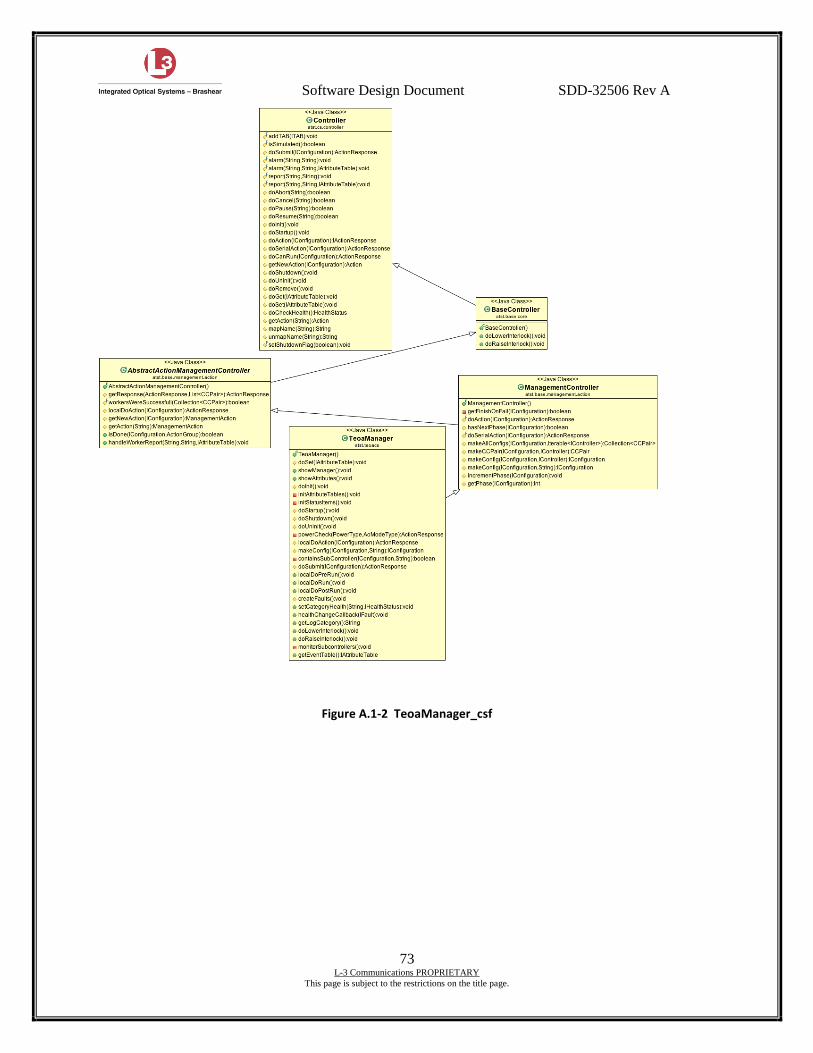
Software Design Document SDD-32506 Rev A
73 L-3 Communications PROPRIETARY
This page is subject to the restrictions on the title page.
Figure A.1-2 TeoaManager_csf
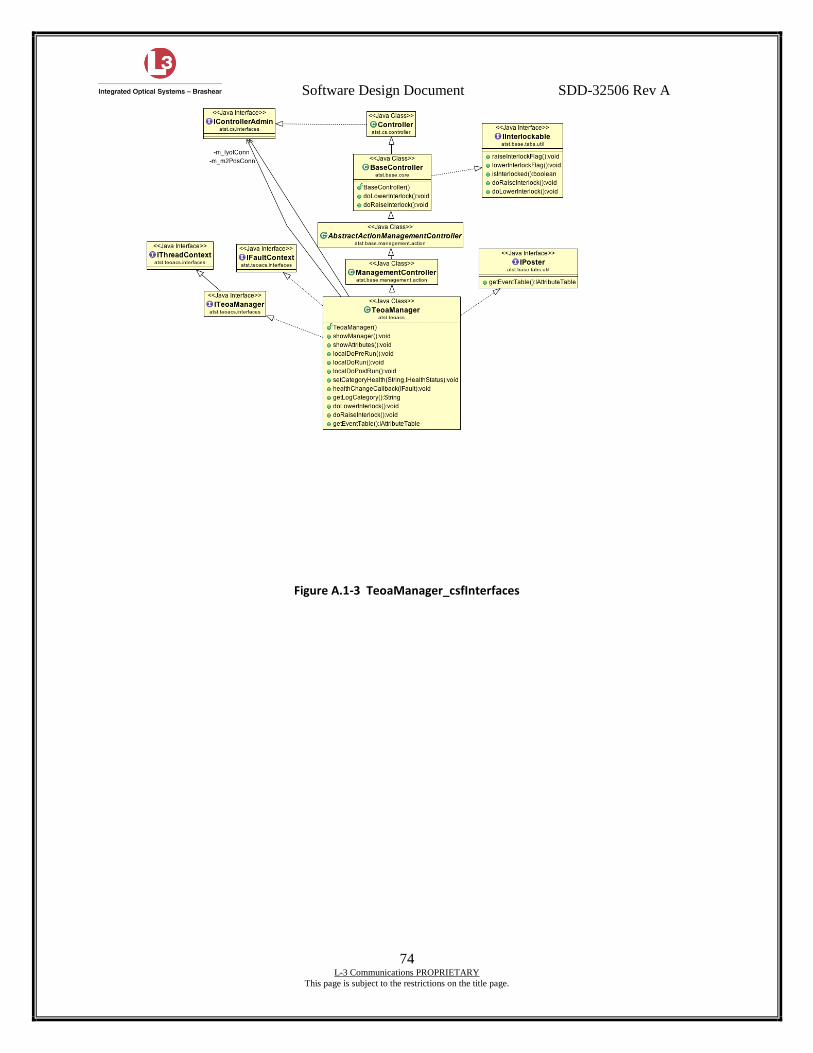
Software Design Document SDD-32506 Rev A
74 L-3 Communications PROPRIETARY
This page is subject to the restrictions on the title page.
Figure A.1-3 TeoaManager_csfInterfaces
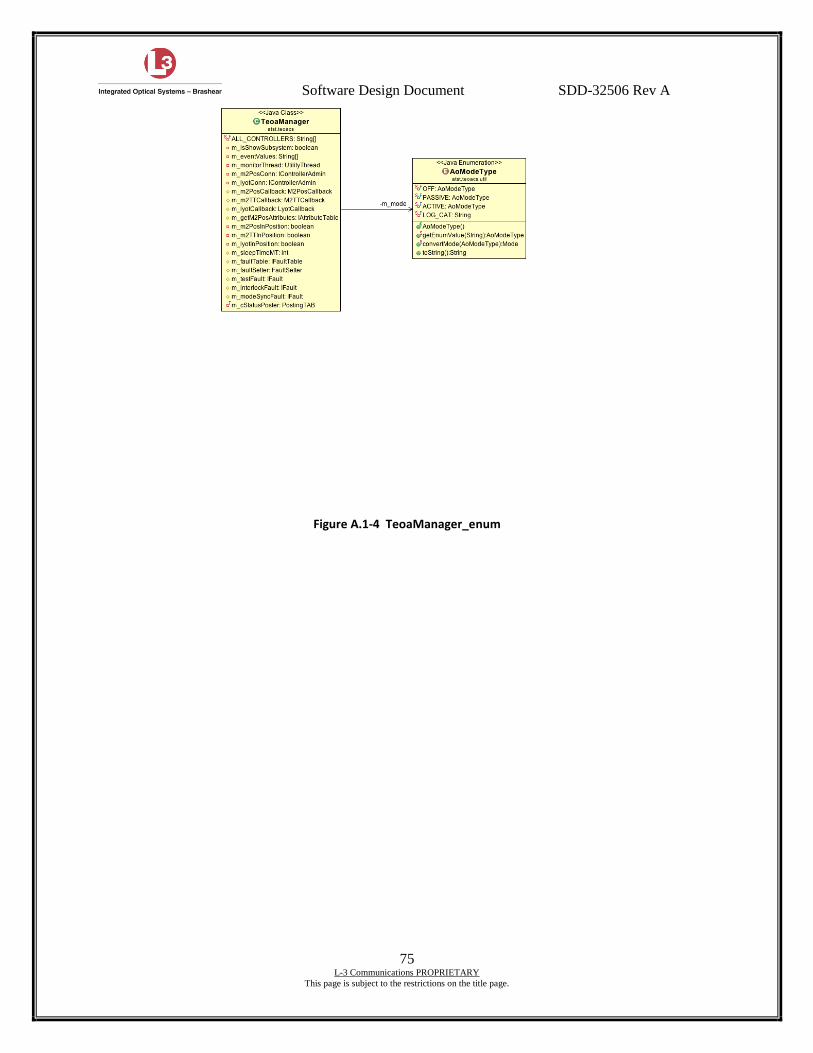
Software Design Document SDD-32506 Rev A
75 L-3 Communications PROPRIETARY
This page is subject to the restrictions on the title page.
Figure A.1-4 TeoaManager_enum

Software Design Document SDD-32506 Rev A
76 L-3 Communications PROPRIETARY
This page is subject to the restrictions on the title page.
Figure A.1-5 TeoaManager_faults
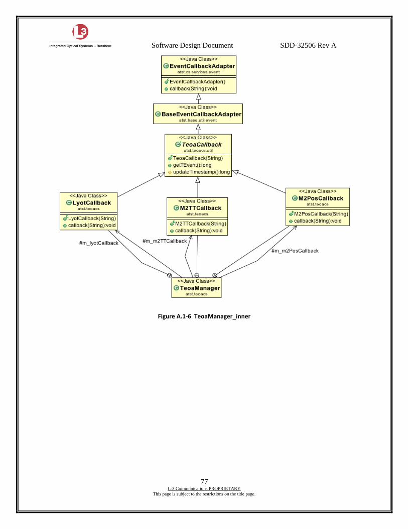
Software Design Document SDD-32506 Rev A
77 L-3 Communications PROPRIETARY
This page is subject to the restrictions on the title page.
Figure A.1-6 TeoaManager_inner
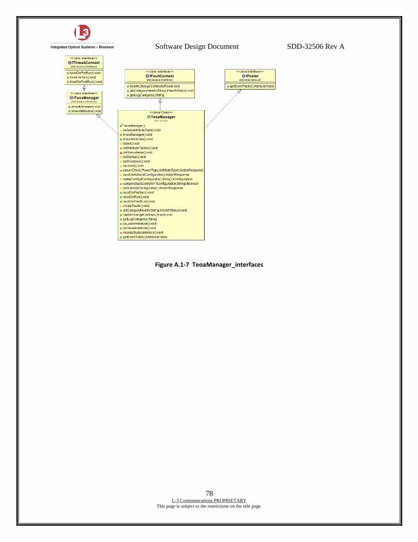
Software Design Document SDD-32506 Rev A
78 L-3 Communications PROPRIETARY
This page is subject to the restrictions on the title page.
Figure A.1-7 TeoaManager_interfaces
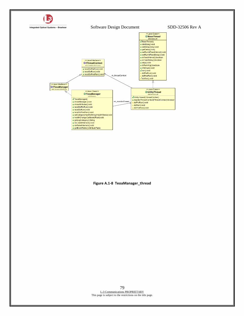
Software Design Document SDD-32506 Rev A
79 L-3 Communications PROPRIETARY
This page is subject to the restrictions on the title page.
Figure A.1-8 TeoaManager_thread
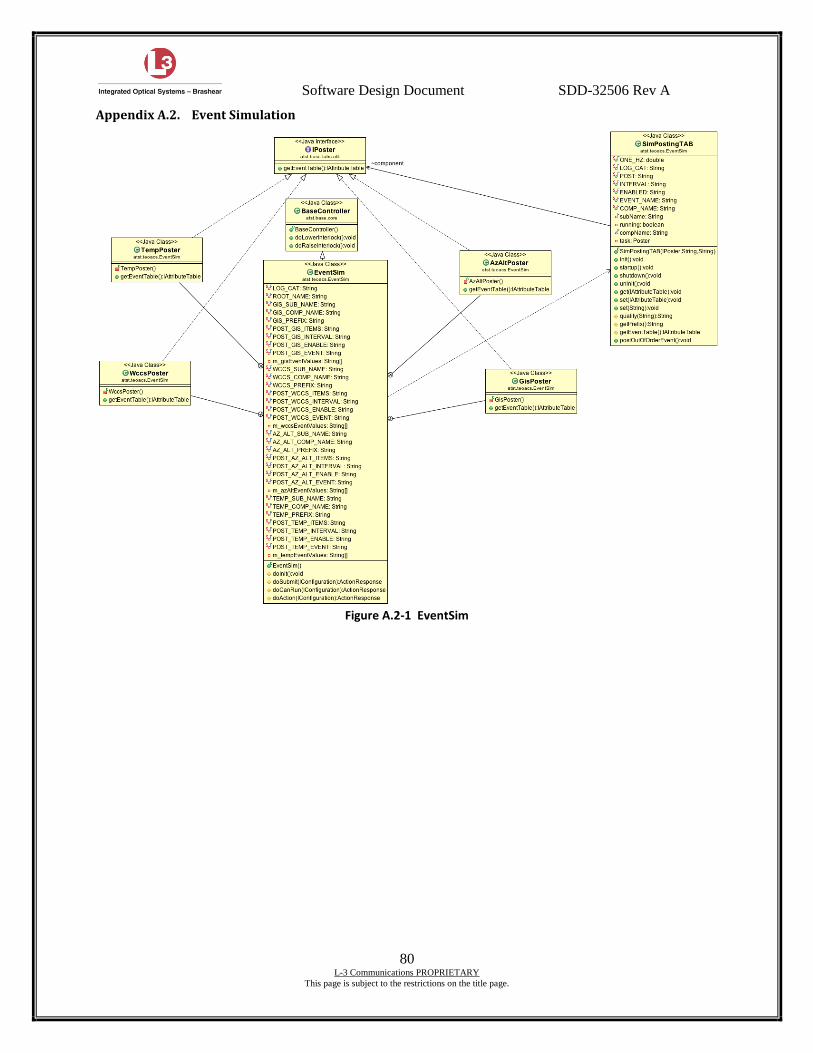
Software Design Document SDD-32506 Rev A
80 L-3 Communications PROPRIETARY
This page is subject to the restrictions on the title page.
Appendix A.2. Event Simulation
Figure A.2-1 EventSim
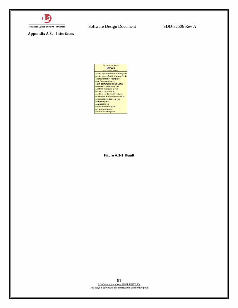
Software Design Document SDD-32506 Rev A
81 L-3 Communications PROPRIETARY
This page is subject to the restrictions on the title page.
Appendix A.3. Interfaces
Figure A.3-1 IFault
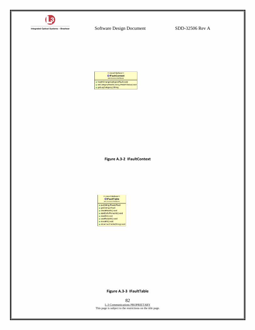
Software Design Document SDD-32506 Rev A
82 L-3 Communications PROPRIETARY
This page is subject to the restrictions on the title page.
Figure A.3-2 IFaultContext
Figure A.3-3 IFaultTable

Software Design Document SDD-32506 Rev A
83 L-3 Communications PROPRIETARY
This page is subject to the restrictions on the title page.
Figure A.3-4 IFttChannel
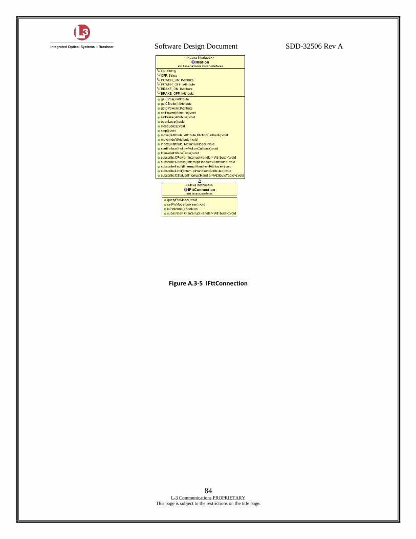
Software Design Document SDD-32506 Rev A
84 L-3 Communications PROPRIETARY
This page is subject to the restrictions on the title page.
Figure A.3-5 IFttConnection
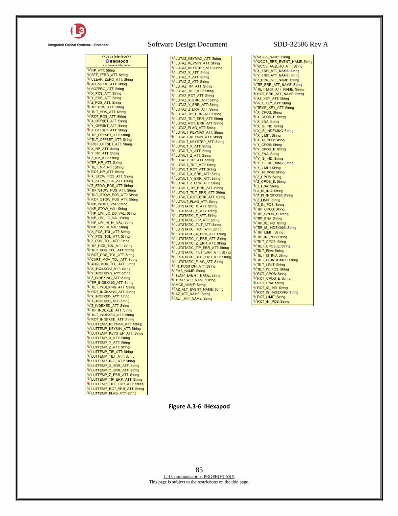
Software Design Document SDD-32506 Rev A
85 L-3 Communications PROPRIETARY
This page is subject to the restrictions on the title page.
Figure A.3-6 IHexapod
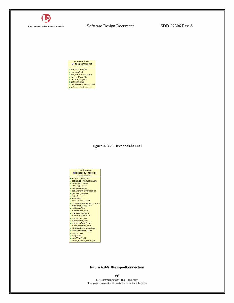
Software Design Document SDD-32506 Rev A
86 L-3 Communications PROPRIETARY
This page is subject to the restrictions on the title page.
Figure A.3-7 IHexapodChannel
Figure A.3-8 IHexapodConnection
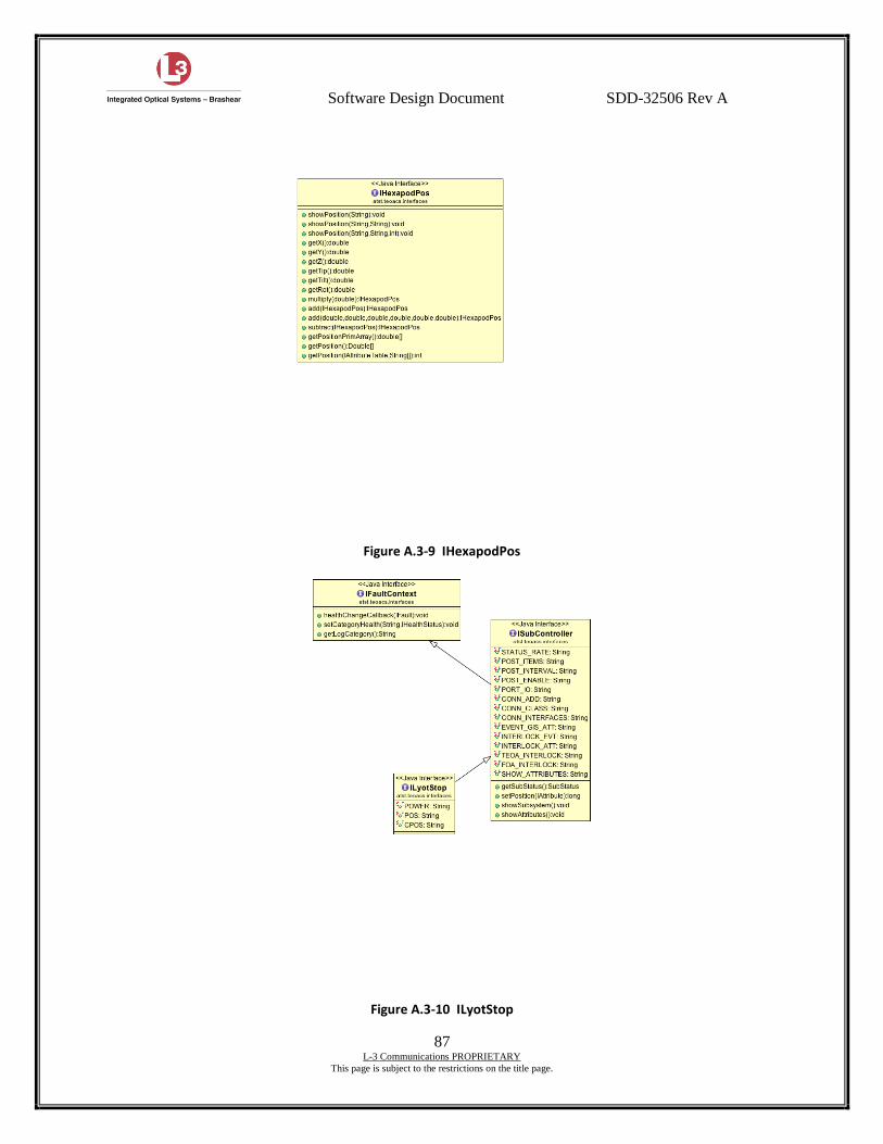
Software Design Document SDD-32506 Rev A
87 L-3 Communications PROPRIETARY
This page is subject to the restrictions on the title page.
Figure A.3-9 IHexapodPos
Figure A.3-10 ILyotStop
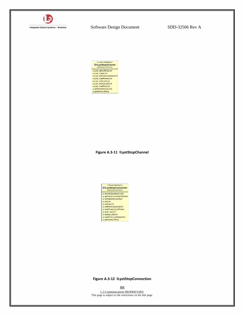
Software Design Document SDD-32506 Rev A
88 L-3 Communications PROPRIETARY
This page is subject to the restrictions on the title page.
Figure A.3-11 ILyotStopChannel
Figure A.3-12 ILyotStopConnection
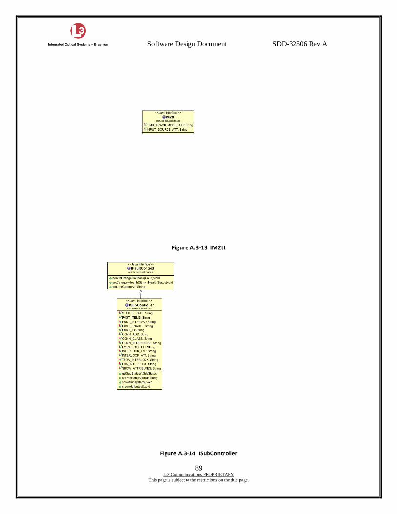
Software Design Document SDD-32506 Rev A
89 L-3 Communications PROPRIETARY
This page is subject to the restrictions on the title page.
Figure A.3-13 IM2tt
Figure A.3-14 ISubController
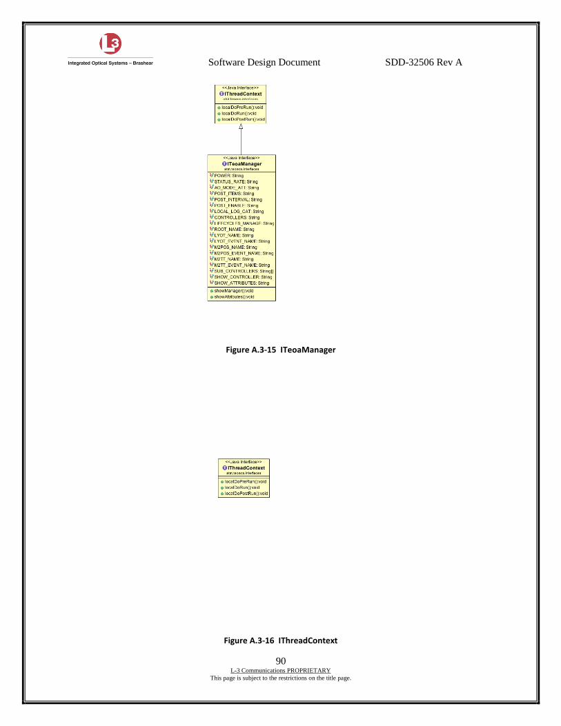
Software Design Document SDD-32506 Rev A
90 L-3 Communications PROPRIETARY
This page is subject to the restrictions on the title page.
Figure A.3-15 ITeoaManager
Figure A.3-16 IThreadContext

Software Design Document SDD-32506 Rev A
91 L-3 Communications PROPRIETARY
This page is subject to the restrictions on the title page.
Figure A.3-17 ITMessage
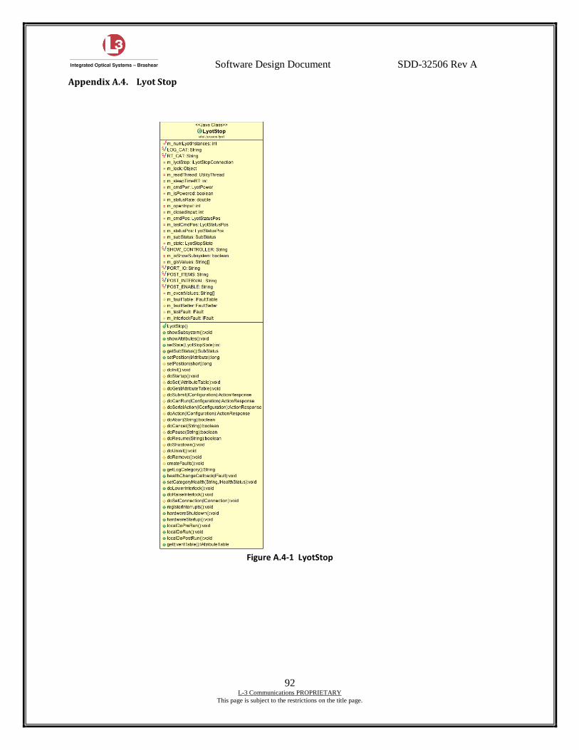
Software Design Document SDD-32506 Rev A
92 L-3 Communications PROPRIETARY
This page is subject to the restrictions on the title page.
Appendix A.4. Lyot Stop
Figure A.4-1 LyotStop
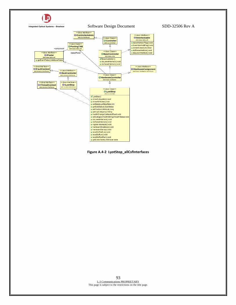
Software Design Document SDD-32506 Rev A
93 L-3 Communications PROPRIETARY
This page is subject to the restrictions on the title page.
Figure A.4-2 LyotStop_allCsfInterfaces
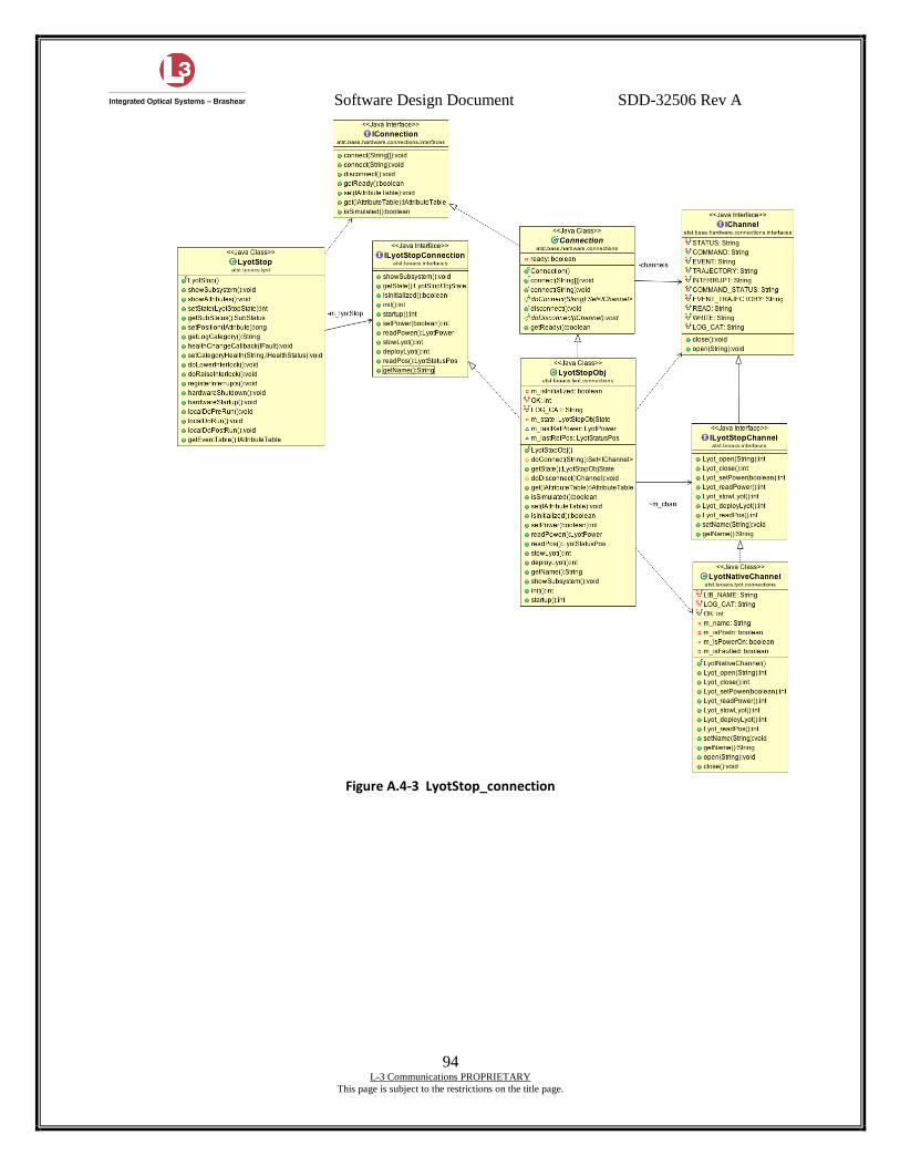
Software Design Document SDD-32506 Rev A
94 L-3 Communications PROPRIETARY
This page is subject to the restrictions on the title page.
Figure A.4-3 LyotStop_connection
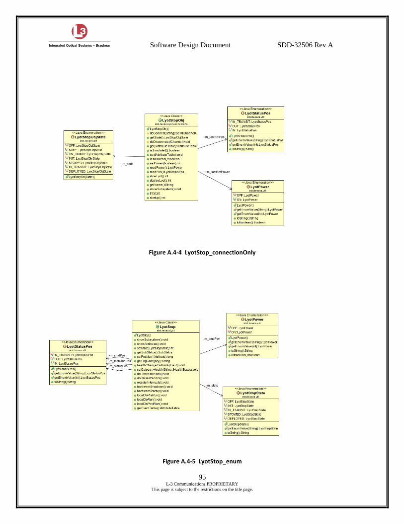
Software Design Document SDD-32506 Rev A
95 L-3 Communications PROPRIETARY
This page is subject to the restrictions on the title page.
Figure A.4-4 LyotStop_connectionOnly
Figure A.4-5 LyotStop_enum
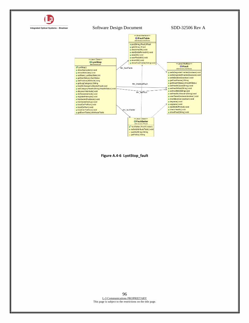
Software Design Document SDD-32506 Rev A
96 L-3 Communications PROPRIETARY
This page is subject to the restrictions on the title page.
Figure A.4-6 LyotStop_fault
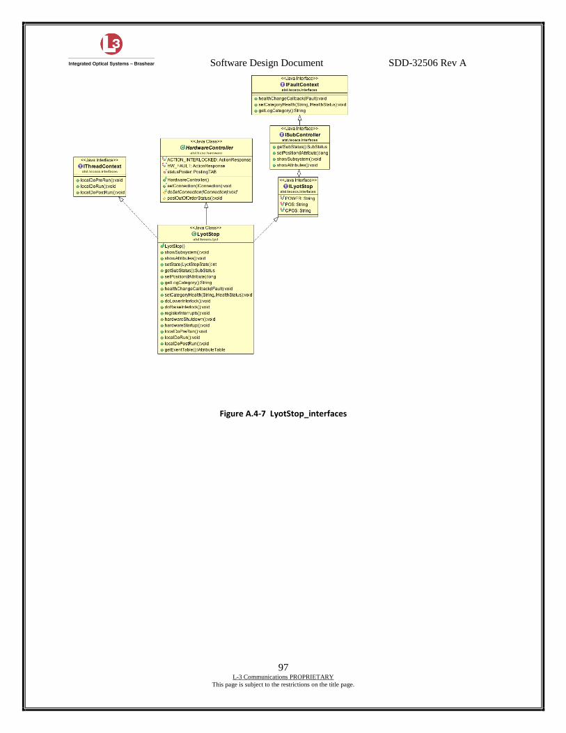
Software Design Document SDD-32506 Rev A
97 L-3 Communications PROPRIETARY
This page is subject to the restrictions on the title page.
Figure A.4-7 LyotStop_interfaces
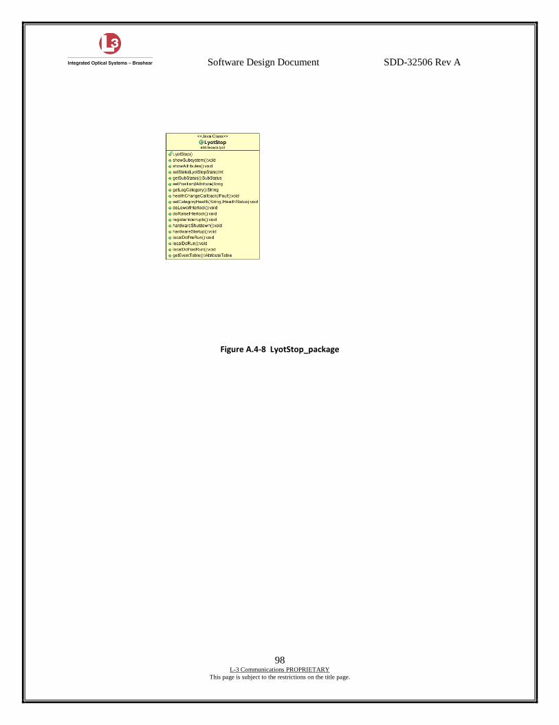
Software Design Document SDD-32506 Rev A
98 L-3 Communications PROPRIETARY
This page is subject to the restrictions on the title page.
Figure A.4-8 LyotStop_package
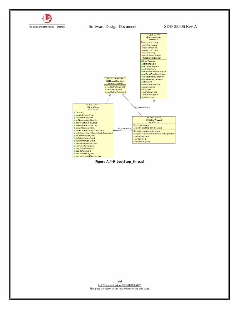
Software Design Document SDD-32506 Rev A
99 L-3 Communications PROPRIETARY
This page is subject to the restrictions on the title page.
Figure A.4-9 LyotStop_thread
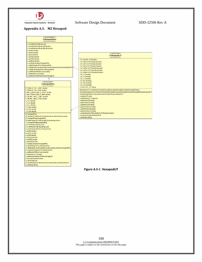
Software Design Document SDD-32506 Rev A
100 L-3 Communications PROPRIETARY
This page is subject to the restrictions on the title page.
Appendix A.5. M2 Hexapod
Figure A.5-1 HexapodLIT
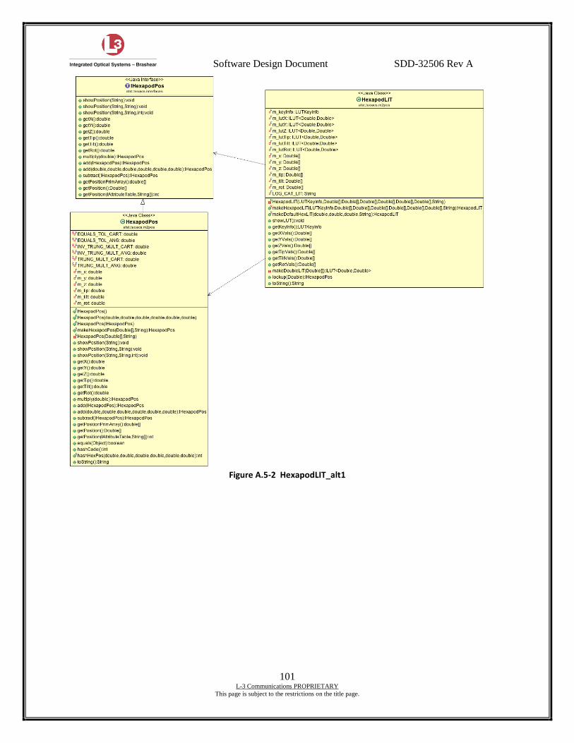
Software Design Document SDD-32506 Rev A
101 L-3 Communications PROPRIETARY
This page is subject to the restrictions on the title page.
Figure A.5-2 HexapodLIT_alt1
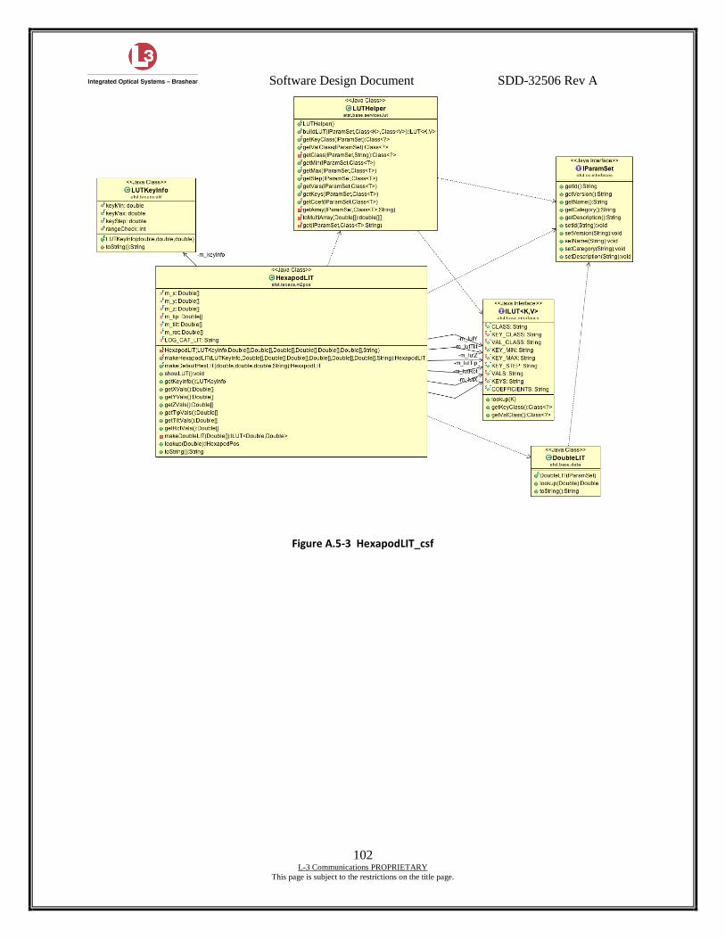
Software Design Document SDD-32506 Rev A
102 L-3 Communications PROPRIETARY
This page is subject to the restrictions on the title page.
Figure A.5-3 HexapodLIT_csf
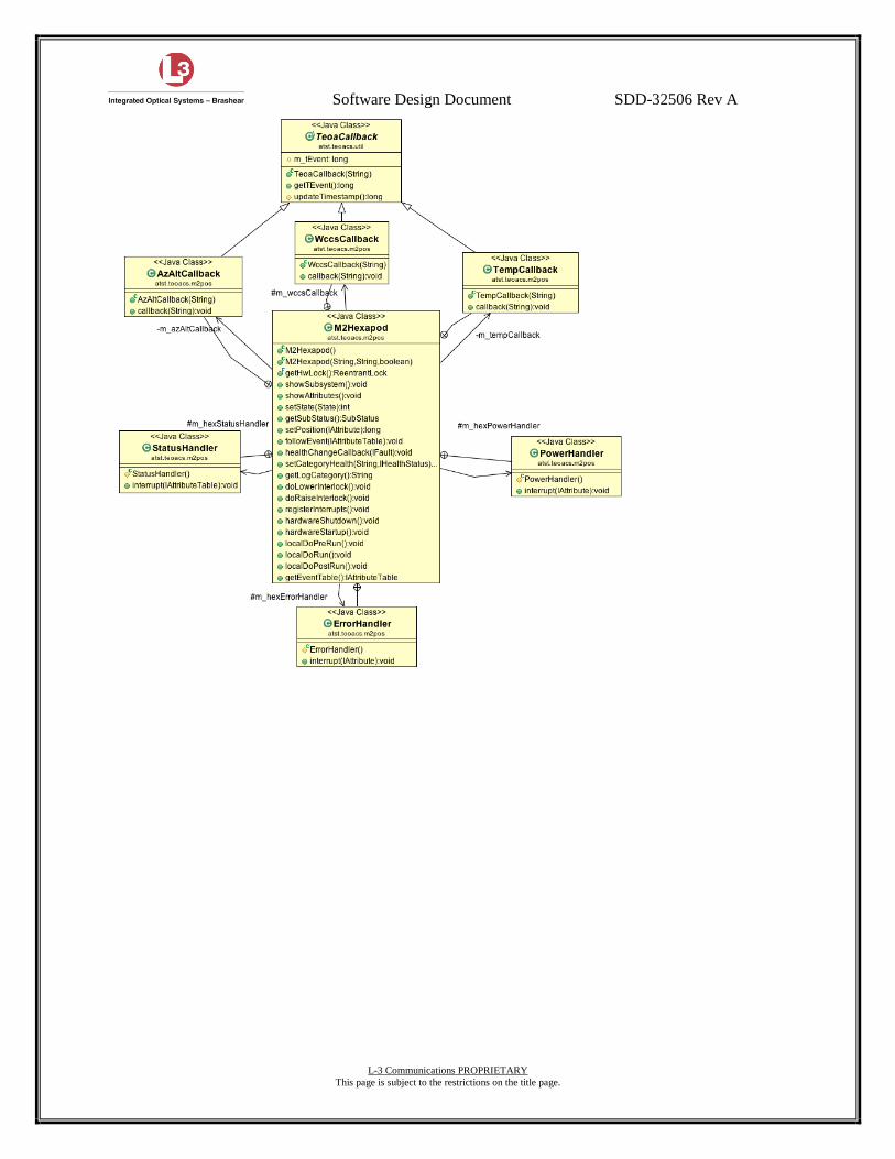
Software Design Document SDD-32506 Rev A
103 L-3 Communications PROPRIETARY
This page is subject to the restrictions on the title page.

Software Design Document SDD-32506 Rev A
104 L-3 Communications PROPRIETARY
This page is subject to the restrictions on the title page.
Figure A.5-4 M2Hexapod+innerClasses
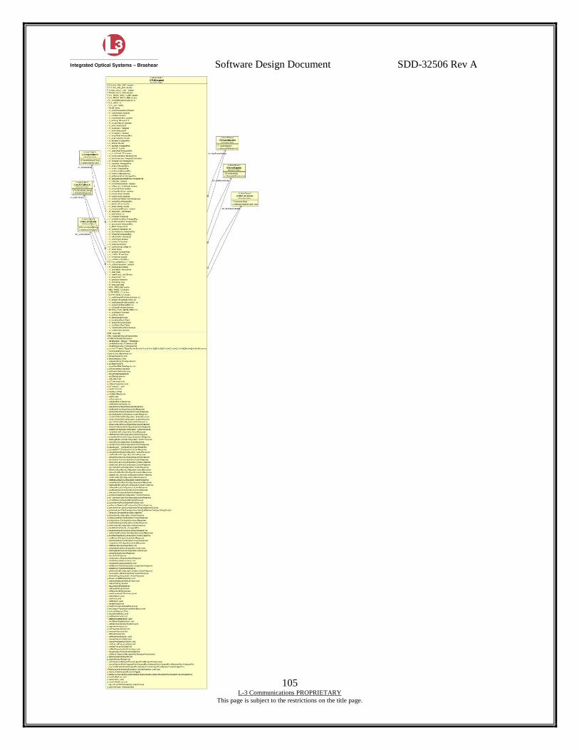
Software Design Document SDD-32506 Rev A
105 L-3 Communications PROPRIETARY
This page is subject to the restrictions on the title page.

Software Design Document SDD-32506 Rev A
106 L-3 Communications PROPRIETARY
This page is subject to the restrictions on the title page.
Figure A.5-5 M2Hexapod

Software Design Document SDD-32506 Rev A
107 L-3 Communications PROPRIETARY
This page is subject to the restrictions on the title page.
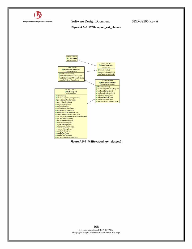
Software Design Document SDD-32506 Rev A
108 L-3 Communications PROPRIETARY
This page is subject to the restrictions on the title page.
Figure A.5-6 M2Hexapod_ext_classes
Figure A.5-7 M2Hexapod_ext_classes2
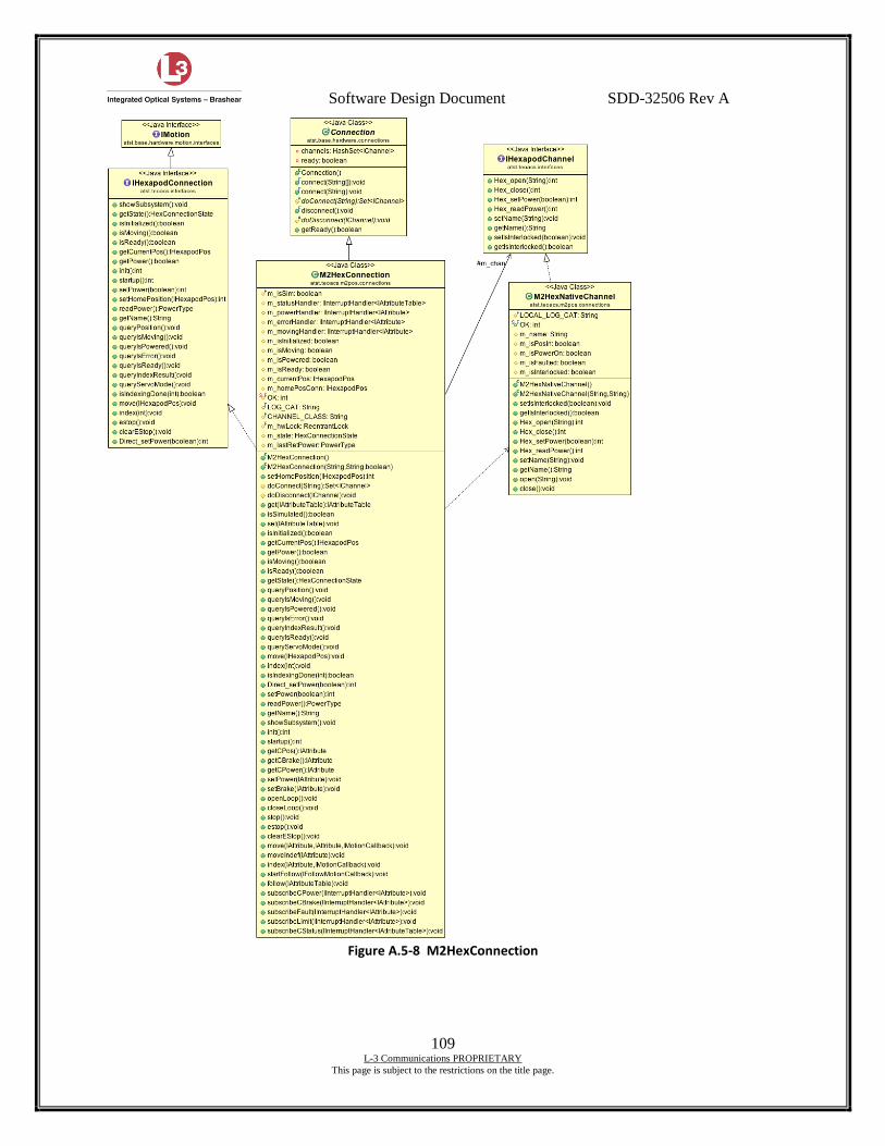
Software Design Document SDD-32506 Rev A
109 L-3 Communications PROPRIETARY
This page is subject to the restrictions on the title page.
Figure A.5-8 M2HexConnection
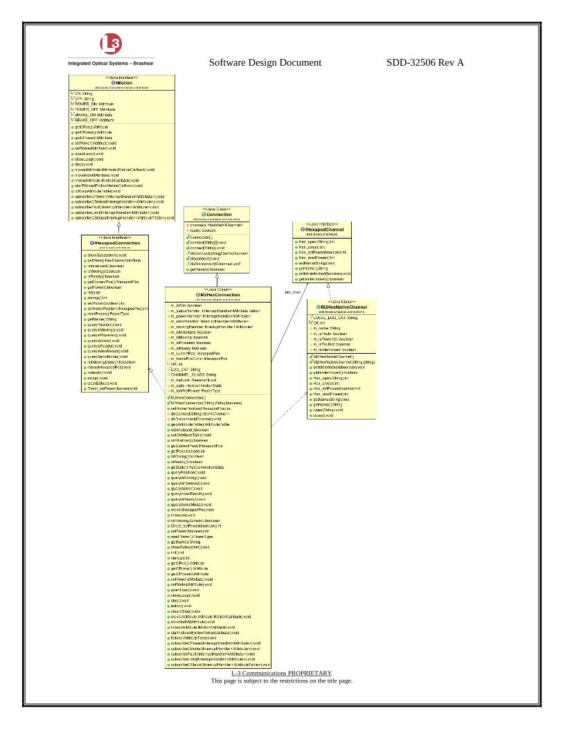
Software Design Document SDD-32506 Rev A
110 L-3 Communications PROPRIETARY
This page is subject to the restrictions on the title page.
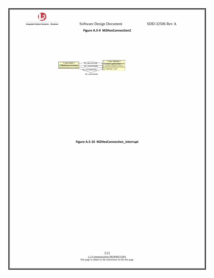
Software Design Document SDD-32506 Rev A
111 L-3 Communications PROPRIETARY
This page is subject to the restrictions on the title page.
Figure A.5-9 M2HexConnection2
Figure A.5-10 M2HexConnection_interrupt
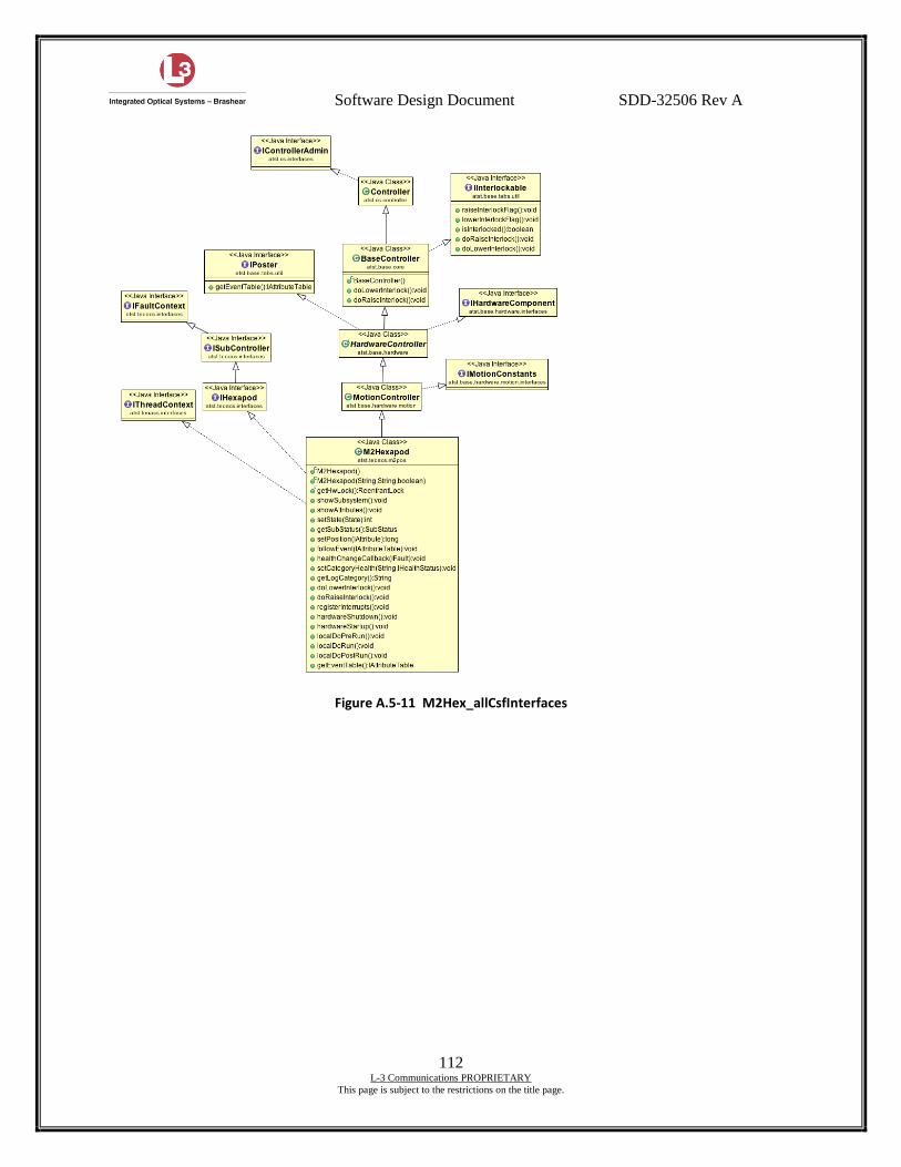
Software Design Document SDD-32506 Rev A
112 L-3 Communications PROPRIETARY
This page is subject to the restrictions on the title page.
Figure A.5-11 M2Hex_allCsfInterfaces
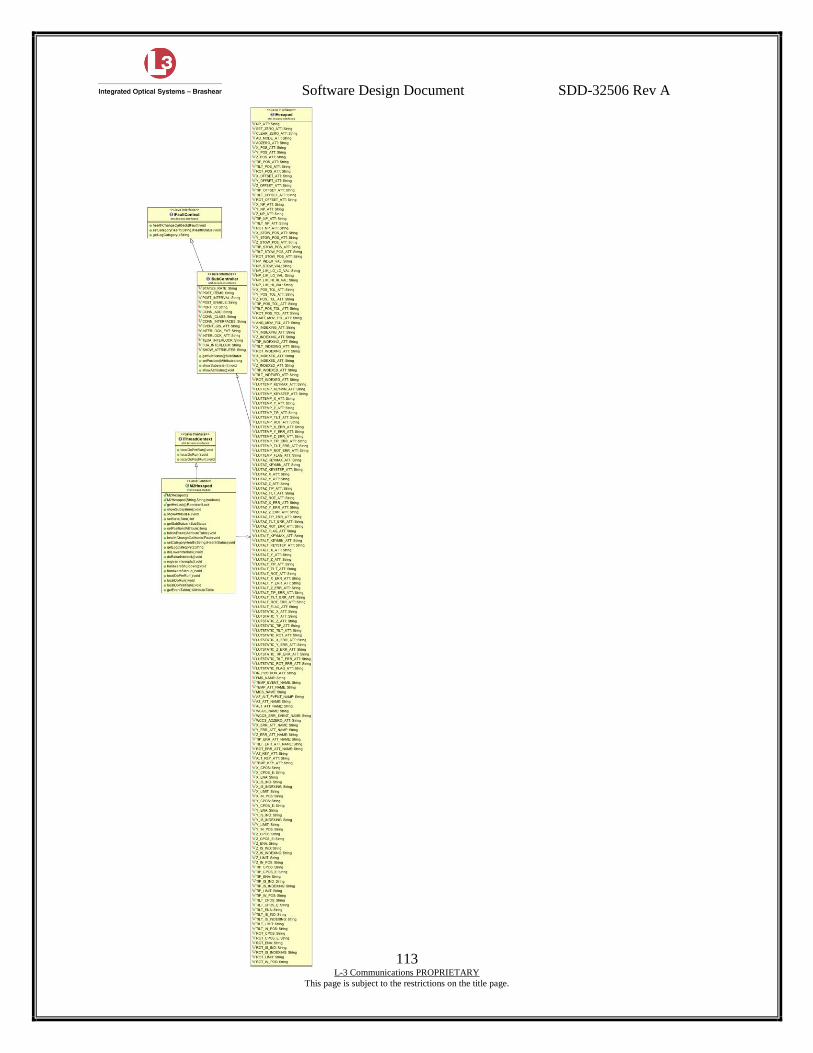
Software Design Document SDD-32506 Rev A
113 L-3 Communications PROPRIETARY
This page is subject to the restrictions on the title page.

Software Design Document SDD-32506 Rev A
114 L-3 Communications PROPRIETARY
This page is subject to the restrictions on the title page.
Figure A.5-12 M2Hex_all_interfaces_fullInterface
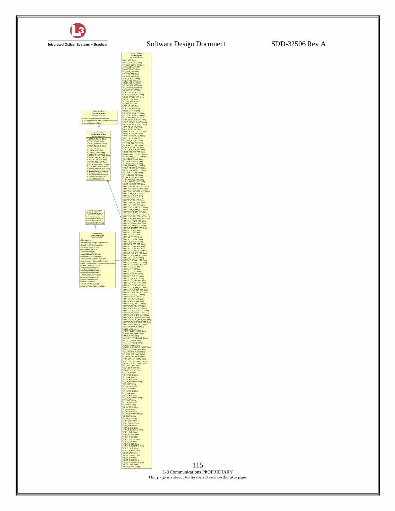
Software Design Document SDD-32506 Rev A
115 L-3 Communications PROPRIETARY
This page is subject to the restrictions on the title page.

Software Design Document SDD-32506 Rev A
116 L-3 Communications PROPRIETARY
This page is subject to the restrictions on the title page.
Figure A.5-13 M2Hex_all_interfaces_partialInterface
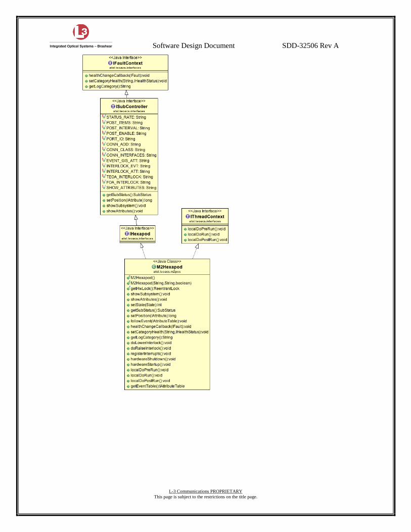
Software Design Document SDD-32506 Rev A
117 L-3 Communications PROPRIETARY
This page is subject to the restrictions on the title page.
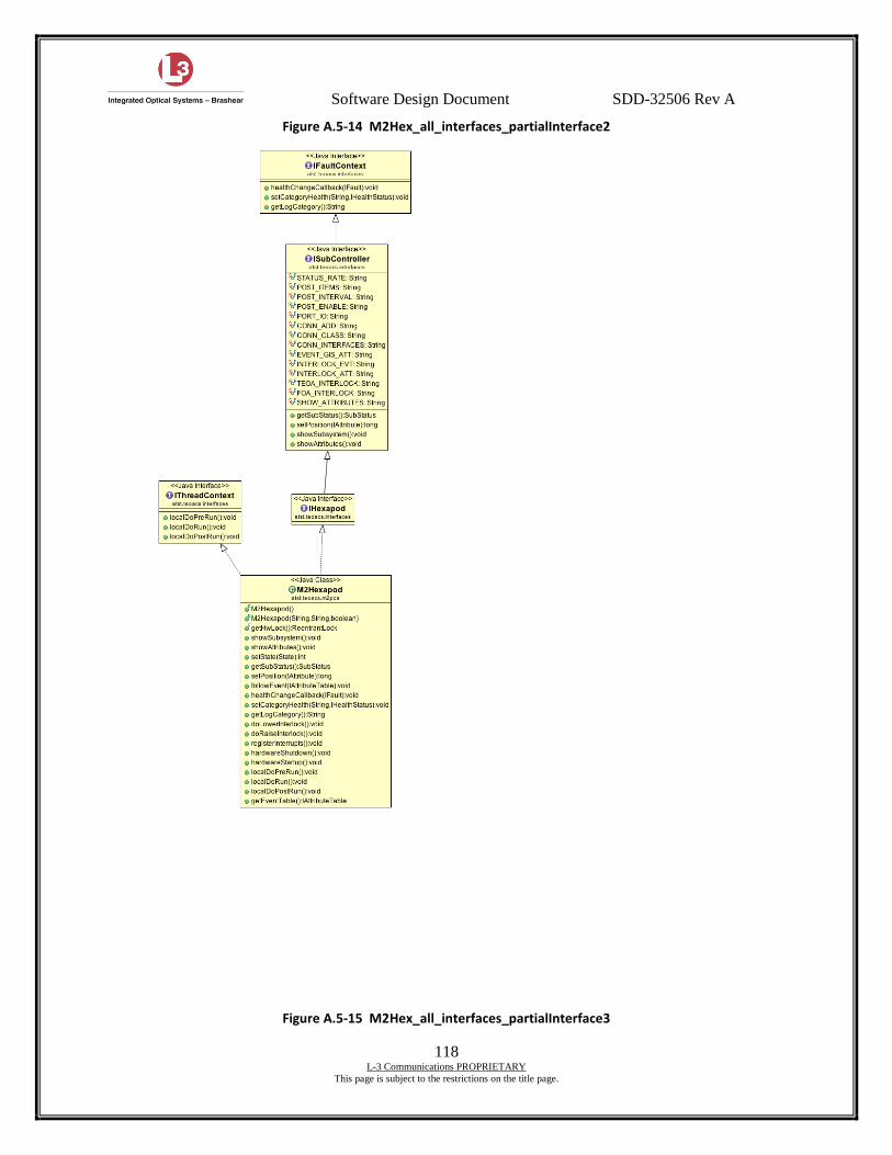
Software Design Document SDD-32506 Rev A
118 L-3 Communications PROPRIETARY
This page is subject to the restrictions on the title page.
Figure A.5-14 M2Hex_all_interfaces_partialInterface2
Figure A.5-15 M2Hex_all_interfaces_partialInterface3
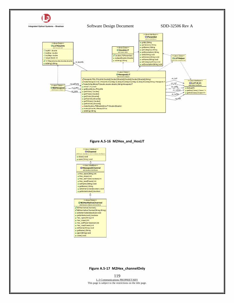
Software Design Document SDD-32506 Rev A
119 L-3 Communications PROPRIETARY
This page is subject to the restrictions on the title page.
Figure A.5-16 M2Hex_and_HexLIT
Figure A.5-17 M2Hex_channelOnly
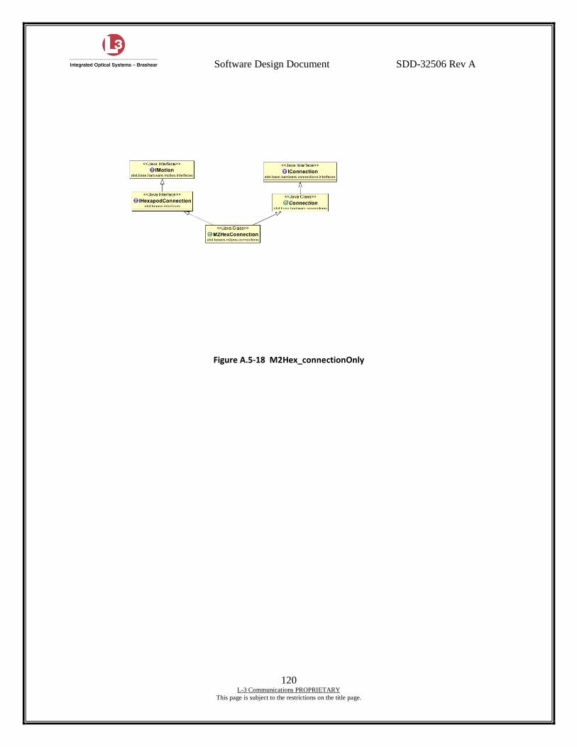
Software Design Document SDD-32506 Rev A
120 L-3 Communications PROPRIETARY
This page is subject to the restrictions on the title page.
Figure A.5-18 M2Hex_connectionOnly
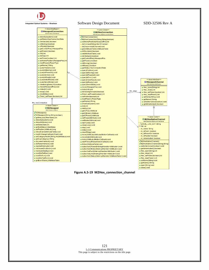
Software Design Document SDD-32506 Rev A
121 L-3 Communications PROPRIETARY
This page is subject to the restrictions on the title page.
Figure A.5-19 M2Hex_connection_channel
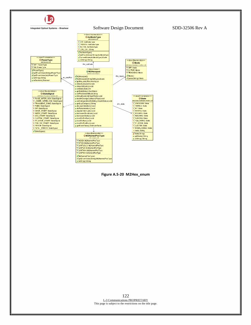
Software Design Document SDD-32506 Rev A
122 L-3 Communications PROPRIETARY
This page is subject to the restrictions on the title page.
Figure A.5-20 M2Hex_enum
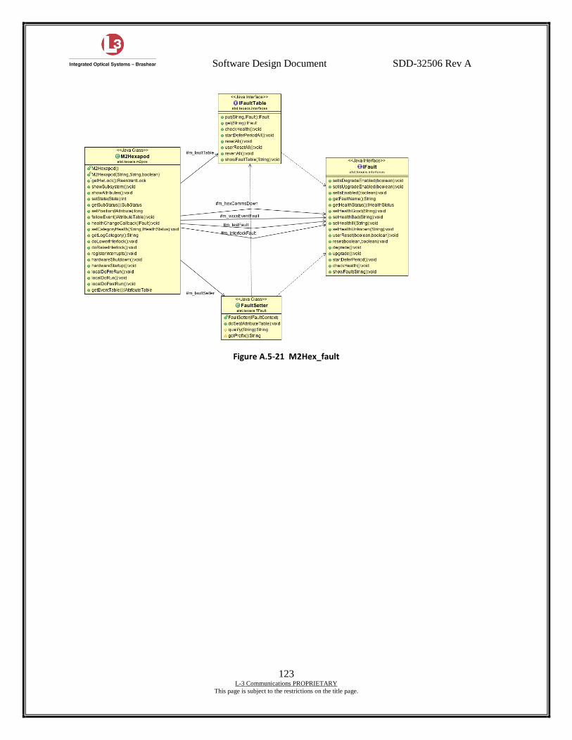
Software Design Document SDD-32506 Rev A
123 L-3 Communications PROPRIETARY
This page is subject to the restrictions on the title page.
Figure A.5-21 M2Hex_fault
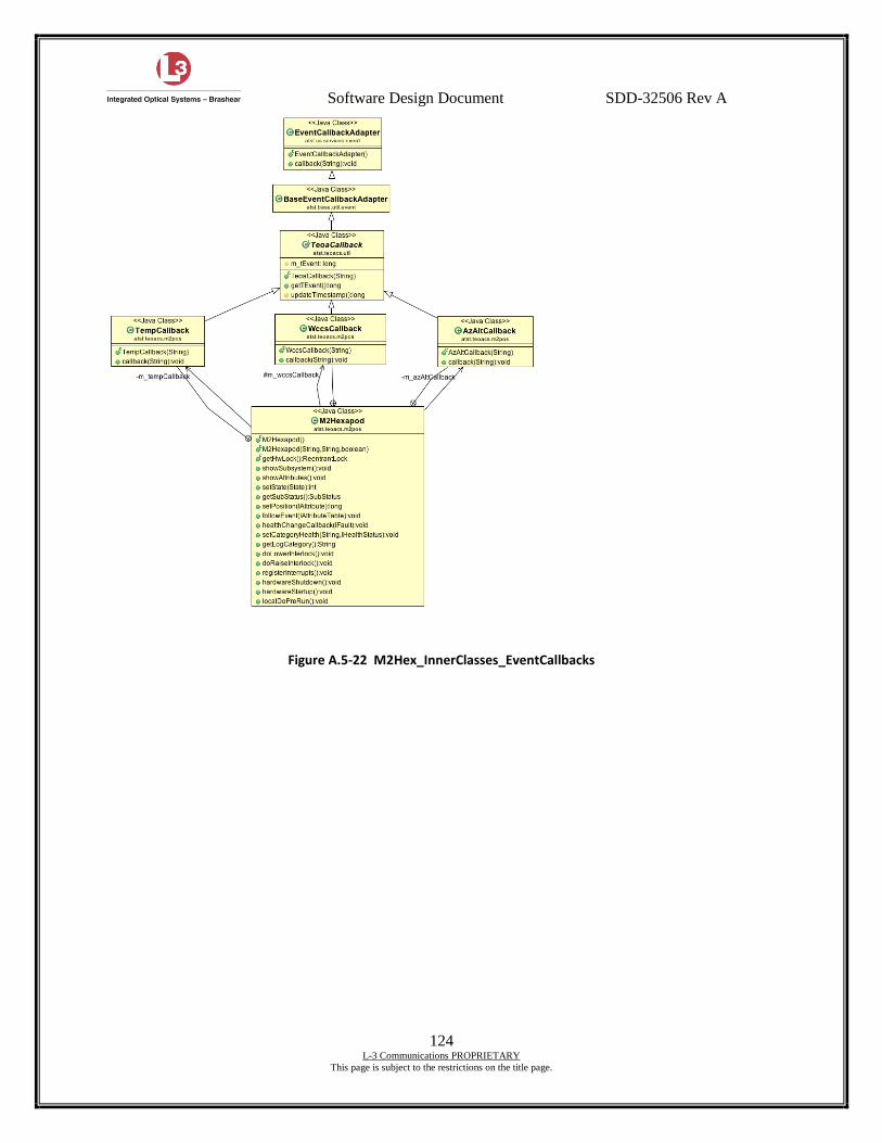
Software Design Document SDD-32506 Rev A
124 L-3 Communications PROPRIETARY
This page is subject to the restrictions on the title page.
Figure A.5-22 M2Hex_InnerClasses_EventCallbacks
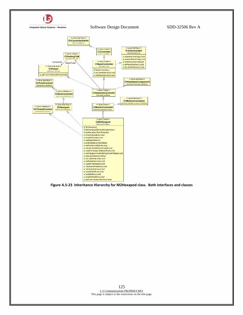
Software Design Document SDD-32506 Rev A
125 L-3 Communications PROPRIETARY
This page is subject to the restrictions on the title page.
Figure A.5-23 Inheritance Hierarchy for M2Hexapod class. Both interfaces and classes
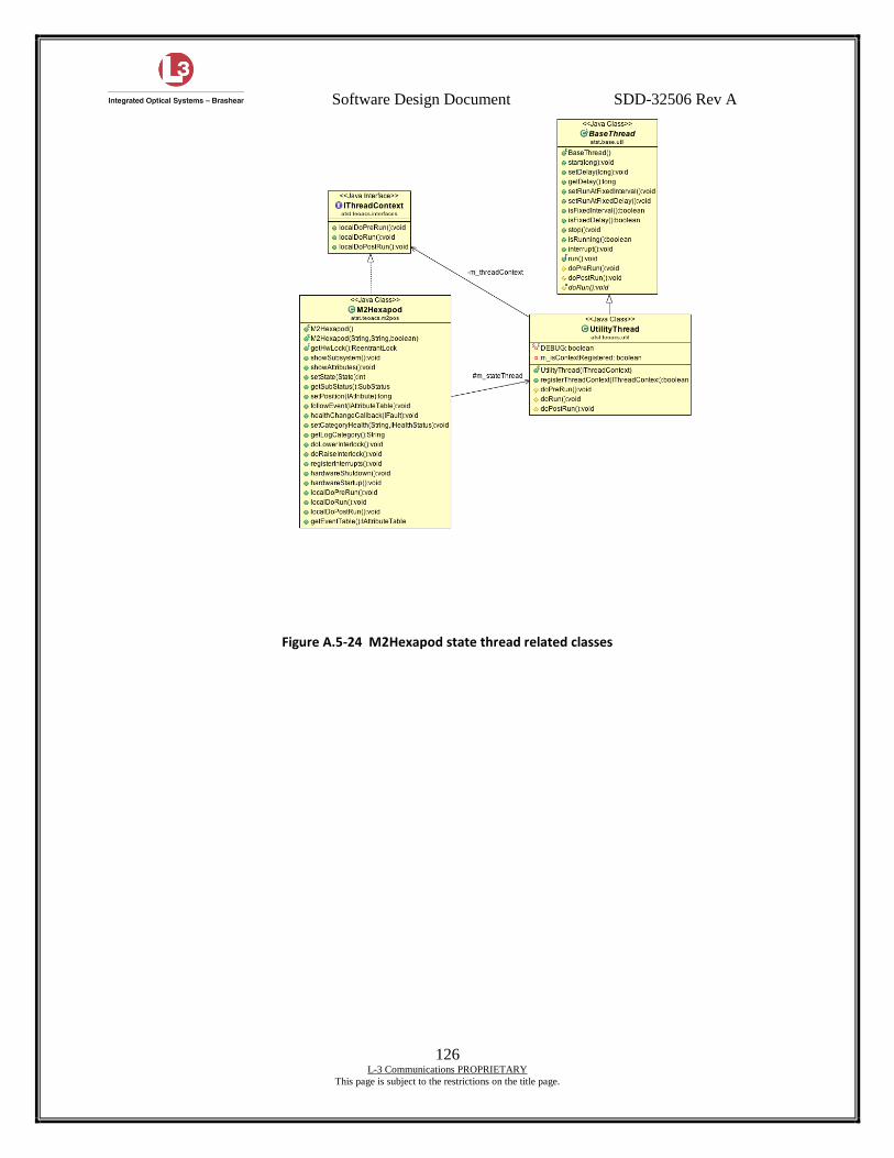
Software Design Document SDD-32506 Rev A
126 L-3 Communications PROPRIETARY
This page is subject to the restrictions on the title page.
Figure A.5-24 M2Hexapod state thread related classes
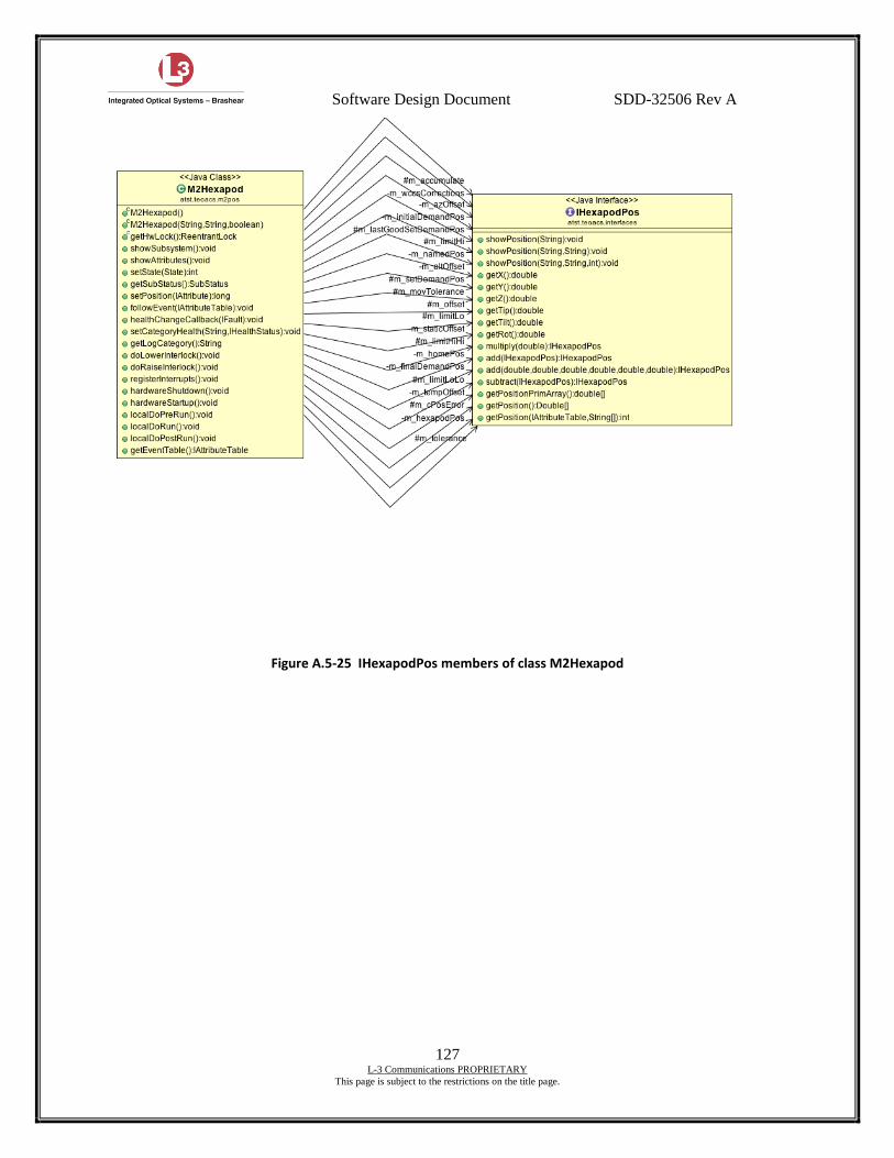
Software Design Document SDD-32506 Rev A
127 L-3 Communications PROPRIETARY
This page is subject to the restrictions on the title page.
Figure A.5-25 IHexapodPos members of class M2Hexapod
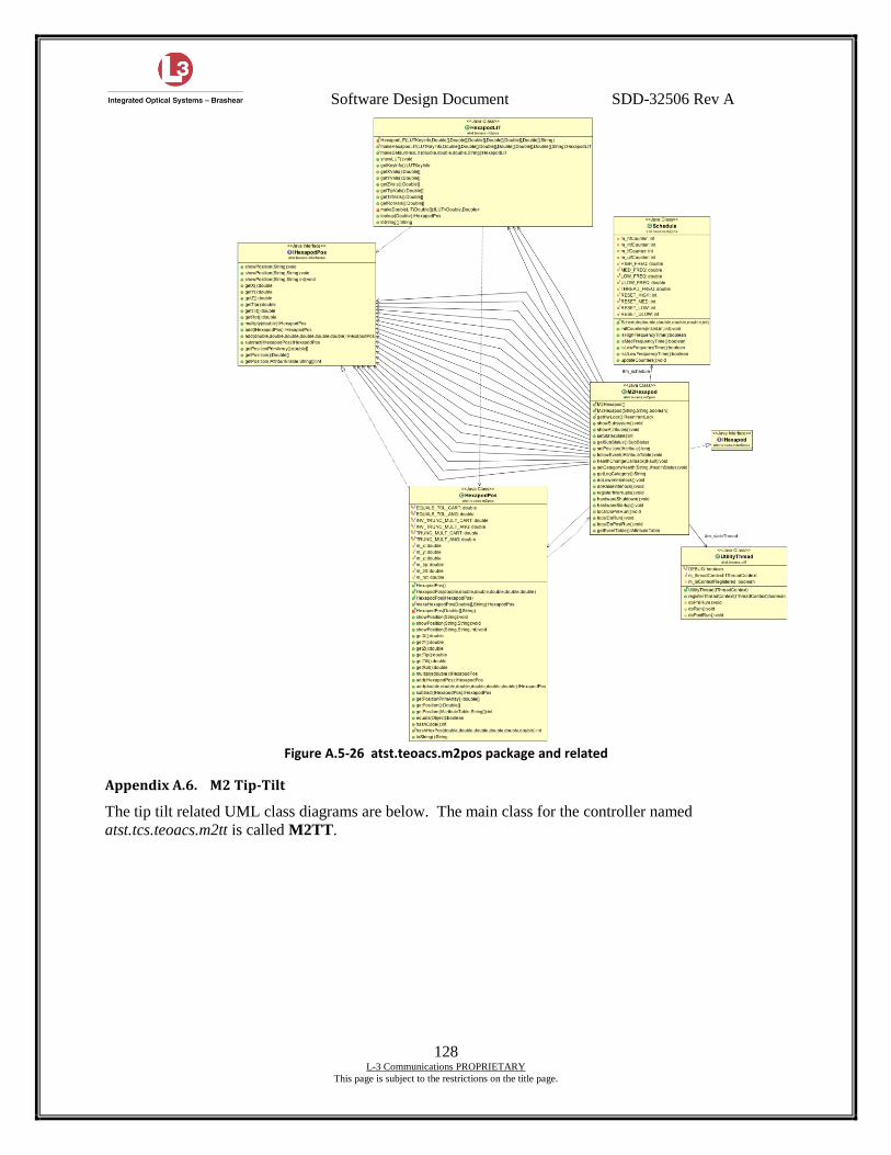
Software Design Document SDD-32506 Rev A
128 L-3 Communications PROPRIETARY
This page is subject to the restrictions on the title page.
Figure A.5-26 atst.teoacs.m2pos package and related
Appendix A.6. M2 Tip-Tilt
The tip tilt related UML class diagrams are below. The main class for the controller named
atst.tcs.teoacs.m2tt is called M2TT.
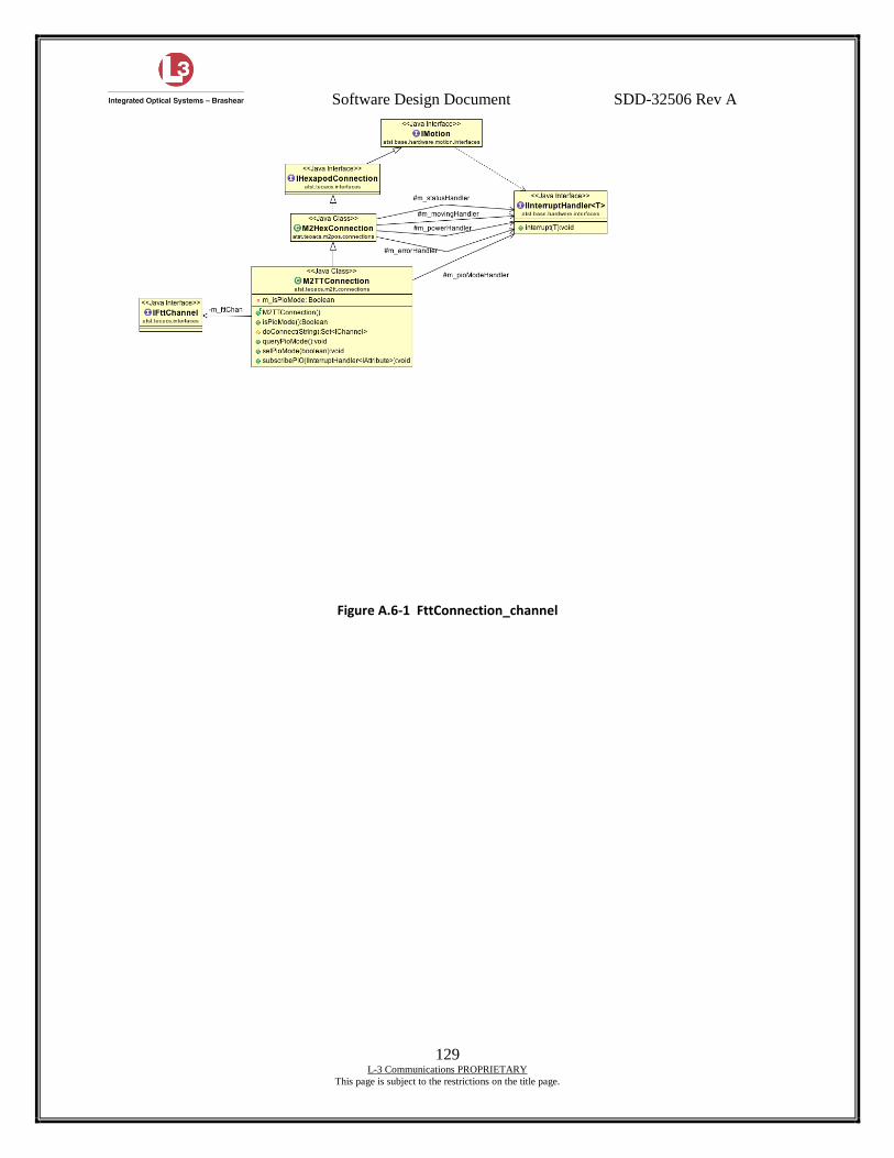
Software Design Document SDD-32506 Rev A
129 L-3 Communications PROPRIETARY
This page is subject to the restrictions on the title page.
Figure A.6-1 FttConnection_channel
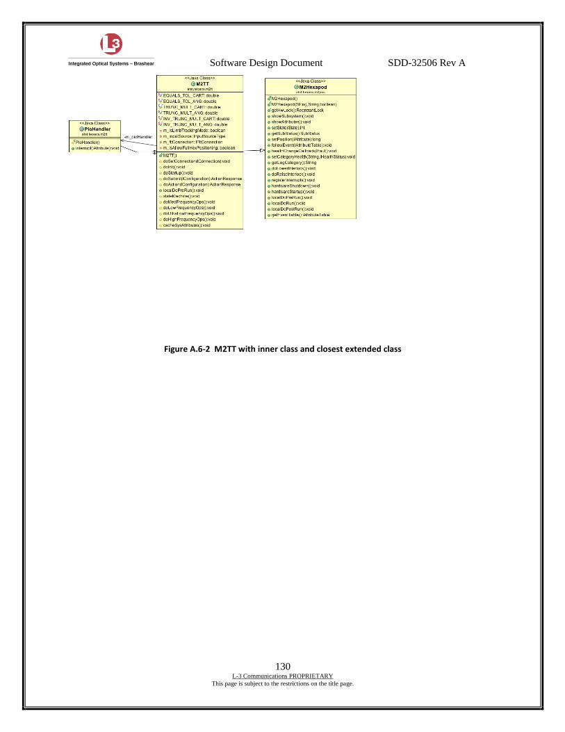
Software Design Document SDD-32506 Rev A
130 L-3 Communications PROPRIETARY
This page is subject to the restrictions on the title page.
Figure A.6-2 M2TT with inner class and closest extended class
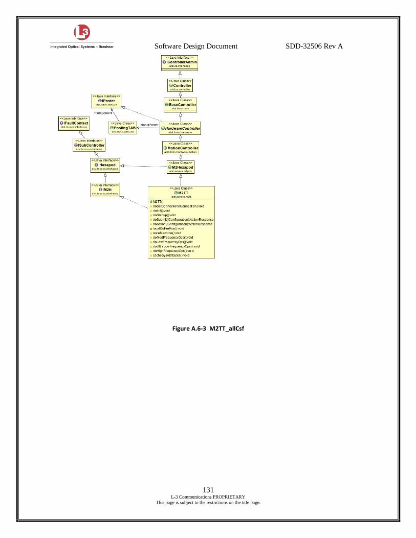
Software Design Document SDD-32506 Rev A
131 L-3 Communications PROPRIETARY
This page is subject to the restrictions on the title page.
Figure A.6-3 M2TT_allCsf
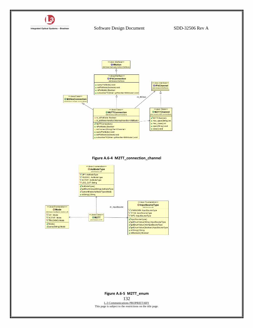
Software Design Document SDD-32506 Rev A
132 L-3 Communications PROPRIETARY
This page is subject to the restrictions on the title page.
Figure A.6-4 M2TT_connection_channel
Figure A.6-5 M2TT_enum
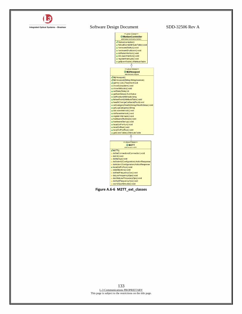
Software Design Document SDD-32506 Rev A
133 L-3 Communications PROPRIETARY
This page is subject to the restrictions on the title page.
Figure A.6-6 M2TT_ext_classes
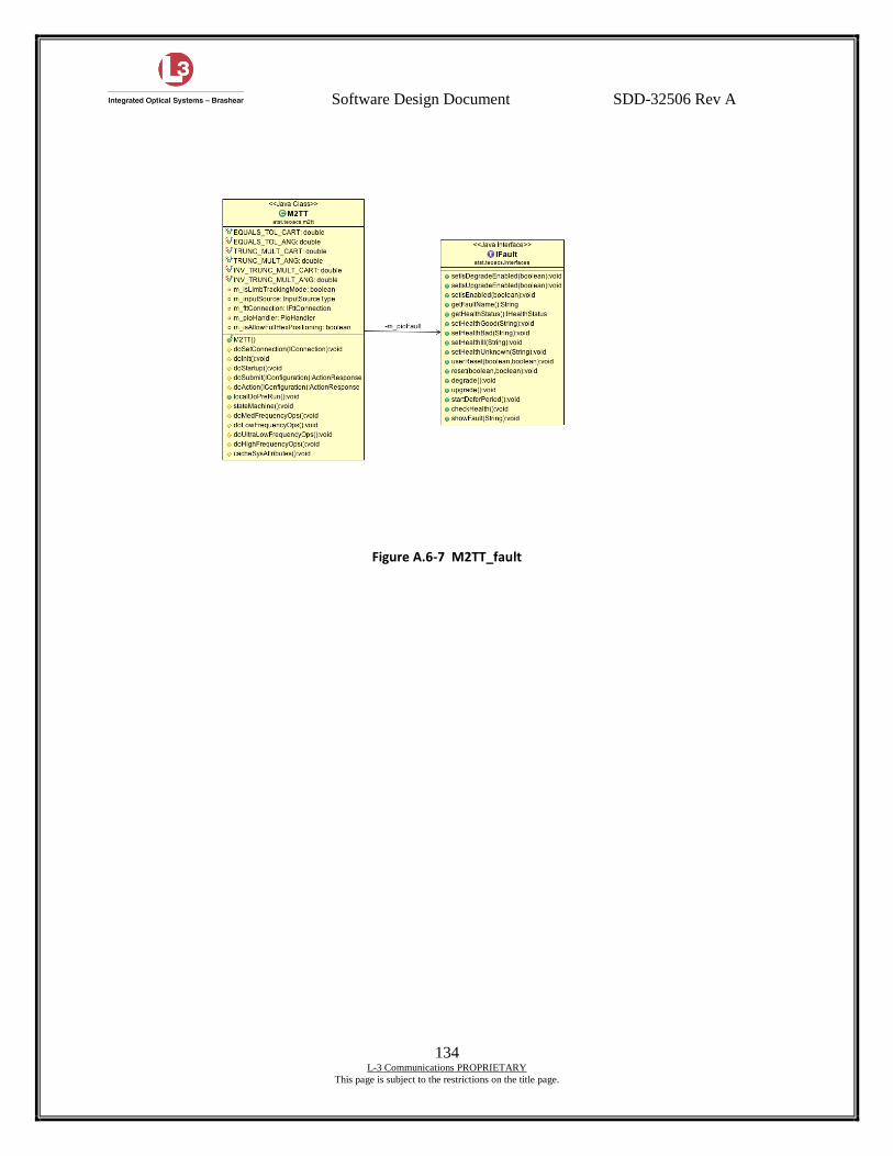
Software Design Document SDD-32506 Rev A
134 L-3 Communications PROPRIETARY
This page is subject to the restrictions on the title page.
Figure A.6-7 M2TT_fault
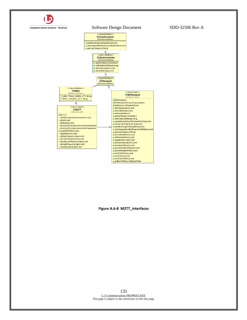
Software Design Document SDD-32506 Rev A
135 L-3 Communications PROPRIETARY
This page is subject to the restrictions on the title page.
Figure A.6-8 M2TT_interfaces
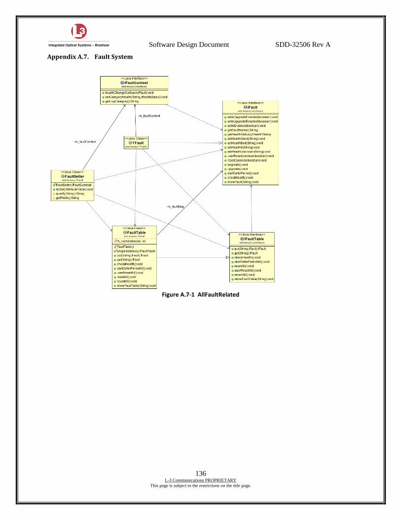
Software Design Document SDD-32506 Rev A
136 L-3 Communications PROPRIETARY
This page is subject to the restrictions on the title page.
Appendix A.7. Fault System
Figure A.7-1 AllFaultRelated
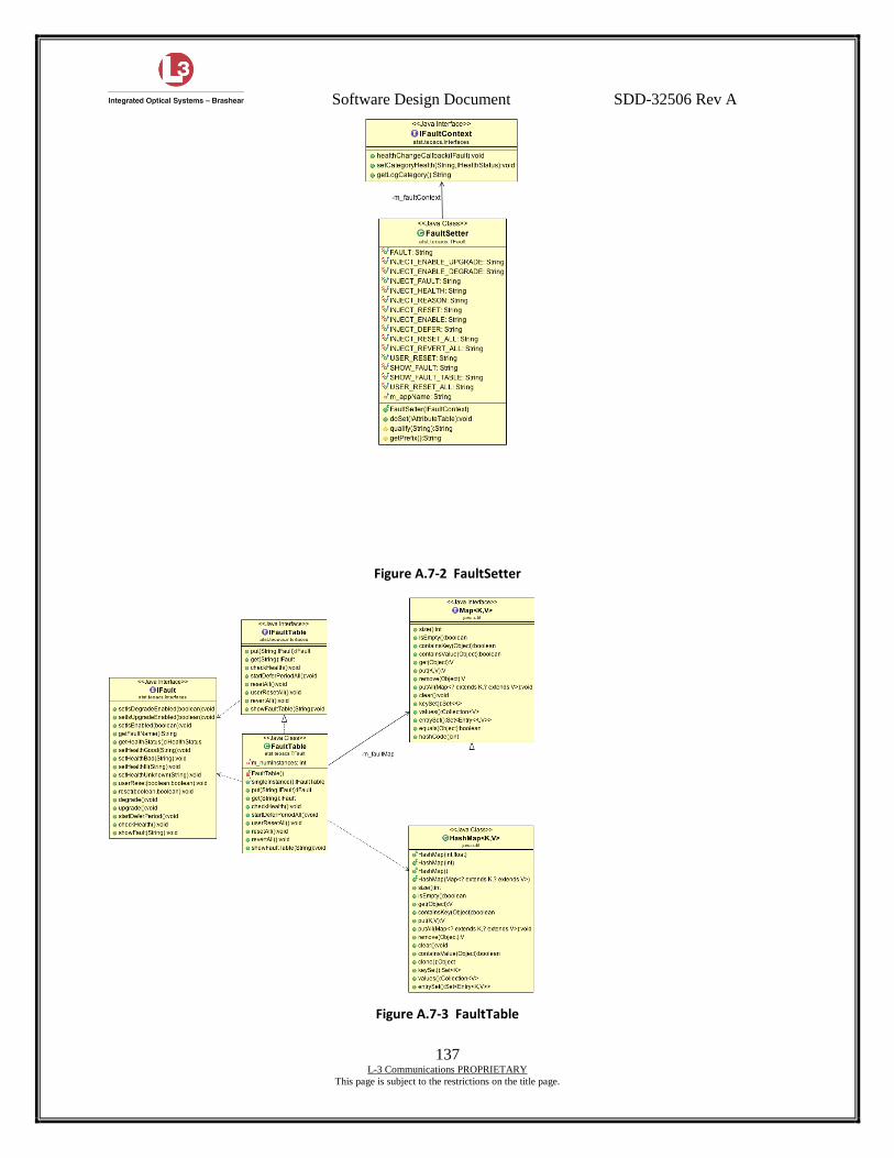
Software Design Document SDD-32506 Rev A
137 L-3 Communications PROPRIETARY
This page is subject to the restrictions on the title page.
Figure A.7-2 FaultSetter
Figure A.7-3 FaultTable
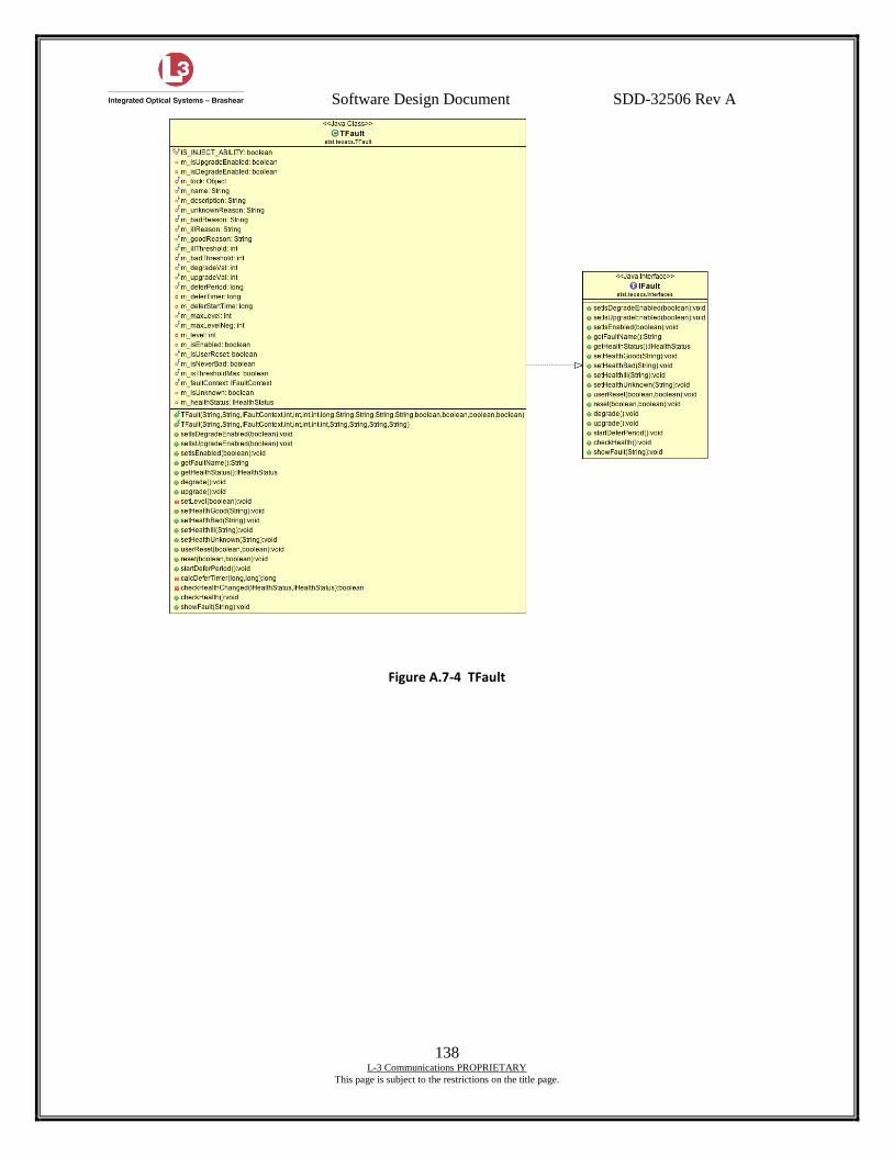
Software Design Document SDD-32506 Rev A
138 L-3 Communications PROPRIETARY
This page is subject to the restrictions on the title page.
Figure A.7-4 TFault

Software Design Document SDD-32506 Rev A
139 L-3 Communications PROPRIETARY
This page is subject to the restrictions on the title page.
Appendix A.8. Utilites
Figure A.8-1 Enumerations
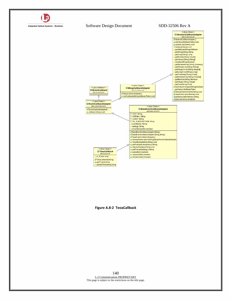
Software Design Document SDD-32506 Rev A
140 L-3 Communications PROPRIETARY
This page is subject to the restrictions on the title page.
Figure A.8-2 TeoaCallback
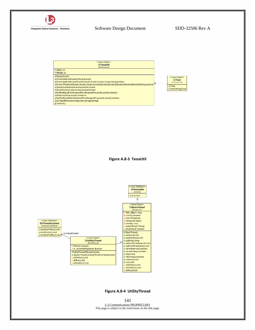
Software Design Document SDD-32506 Rev A
141 L-3 Communications PROPRIETARY
This page is subject to the restrictions on the title page.
Figure A.8-3 TeoaUtil
Figure A.8-4 UtilityThread
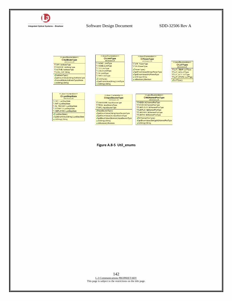
Software Design Document SDD-32506 Rev A
142 L-3 Communications PROPRIETARY
This page is subject to the restrictions on the title page.
Figure A.8-5 Util_enums