Embed Size (px)
Citation preview

Software Defined Radio
Graham KingG3XSD

Content
● The context of the rise of Software Defined Radio (SDR)
● The reliance on Digital Signal Processing (DSP)
● General architectures● Technical discussion of significant constituent
parts● Conclusions and Questions

What is it?A radio system in which:
● Most of the complex signal handling uses DSP– Filters– Noise Reduction/processing– Voice compression etc etc
● Provides RF Spectrum and waterfall displays using FFTs, in Panadapter style
● User interface is through a computer● Often using some form of direct conversion● Uses a computer to run software and control rig

Who wants it?
● Mainly radio manufacturers● Why? Progress is so fast these days that they want
to create systems that could be upgraded, updated easily
● This requires a near universal set of hardware ( computers are universal machines)
● This also requires functionality/performance/control defined by software
● But also, Radio Amateurs benefit from clever systems with reduced obsolescence

The simplest architecture(Softrock)

What is DSP?Digital Signal Processing
● Signals are sampled, and the sampled data sequences are processed by:
● shift registers,flipflops,logic gates,● correlators/fast convolution● FFT/DCT butterflies● Various other transforms ( e.g.Hilbert)● ALL implemented as recurrence formulae in
SOFTWARE running on a DS Processor or as logic in a FPGA or such like.

Digital Signal Processor?
● A staggeringly fast CPU, usually with multiple parallel ALUs and multiple parallel FFT butterflies
● Most are SIMD – single instruction multiple data set i.e. can perform 128 FFTs or more, all at once – BANG! Done!
● FPGA – Field Programmable Gate Array chips – implement your recurrence formula by interconnecting gates according to your design

Direct Conversion?
● What was wrong with the TRF?● Gain at HF and also Selectivity (BW=fr/Q)
● Has anything changed since the triode and LC tuned circuits?● DSP brick wall filters● SAW filters ( to 3 GHz)● FET RF amplifiers etc etc......
● Time to give it another go?

Anything else involved?Yes, A to D and D to A conversion
● Recent developments of cheap high resolution and fast chips for this:
● Fast? Remember the Nyquist frequency. To work up to 30MHz you must sample at least 60 Mb/s to avoid aliasing
● Resolution? 32 bit now possible – reduces quantisation error (noise)

How do analogue and digital cctsrelate?
● These are functionally the same!
yn = 0.5(x1+δx0)
This can be scaled up hugelyHow do you do an FFT1?

How do you do an FFT (DFT)2An 8 point transform
● 12 Butterflies! ( Decimation in Time algorithm - Sande-Tukey)

The software is not so bad!Zoran Vector Signal Processor Assembler
Begin/* Load the 16 data points into internal RAM EVEN points first*/LD NMPT:8,MBS:8,MSS:2,MBA:SIGNAL/* Store consecutively /*ST NMPT:8,MBS:8,MSS:8, MBA:REORDER
/*Read in the odd sample points and reverse order them */LD NMPT:8,MBS:8;MSS:2,MBA:SIGNAL+1Load the other half beginning with sample 1, e.g. 1,3,5,7,9,11,13,15. RV=1
STB NMPT:8,MBS:8,MSS:8, MBAB:REORDER+8
/* Load the re-ordered data back into the processor */LD NMPT:16,MBS:16,MSS:16,MBA:REORDER/* Do the FFT DIT in 4 passes */FFT NMBT:8, R:1,FPS:1,LPS:8,I:0,RS:1
/* Output to memory for use by other routines/methods etc */ST NMPT:16,MBS:16,MSS:16,RS:0,MBA:RESULT

IQ modulation/demodulationone more concept!
● Does it all! PSK QPSK QPAM AM [SSB*] CW FM + ● 2 sigs, Sine and Cosine, interpretive algorithms
* in combination with additional bits! See later....

● All we have talked of is usually provided in a box
● Add PSU and PC,antenna ( and a TX if box is RX only).
● Or if SDR Rx in a stick,just plug in to a USB port.
Architecture options

Receivers
● Receiver
● There are many variations. Some use a traditional radio front-end and operate on an IF signal
● Increasingly popular is Direct conversion, giving a wide band front end to an IQ demodulator followed by SDR techniques
● We shall concentrate on Direct conversion– Softrock, Fun Cube, SDR-Radio,RTL-SDR, and all sticks
using the RL2832U/Elonics E4000 chip

Direct conversion receiverhttp://vaedrah.angelfire.com

Transmitter

Phasing Method

Hilbert Transform 1
● In signal processing, the Hilbert transform is a linear operator which takes a function, u(t), and produces a function, H(u)(t), with the same domain
● There are many Hilbert Transforms but the one we are interested in is an operator that shifts a signal by -90 degrees: All Pass
● This can be thought of as the convolution of u(t) with the function h(t) = 1/(πt)

Hilbert Transform 2-90 in software
● The transform is equivalent to:two all-pass IIR filters whose phase difference is approximately 90 degrees over a range of frequencies symmetric around Nyquist/2
● For this there is transfer function expressed as a recurrence formula
● This job can be done by 8 multiplies and a final scaling by 0.5 ( Niemitelo 2003 http://yehar.com/blog/?p=368)

Hilbert transform 3
● Refer to the Phasing Method diagram......● Hilbert transforms are used twice
– Once for the carrier.....easy: a single frequency– Once for the AF input : not so easy 300Hz-2.4KHz– Delay is to compensate for the group delay in the
transform.● This was a problem for hardware implementations
– See next slide● It is still a problem for software implementations!
– See Slide Hilbert 2

Hilbert Transform (-90 degs)Hardware implementation

Can we make it easier?
● Yes, devise a circuit that does not require the -90 degree phase shift consistent and accurate over 300Hz to 2.4 Khz
● An alternative requiring two carriers BUT using two single frequency -90 degree shifts only was designed by Weaver
● We now call it the THIRD method● In near monopoly use for Software Defined
Radio

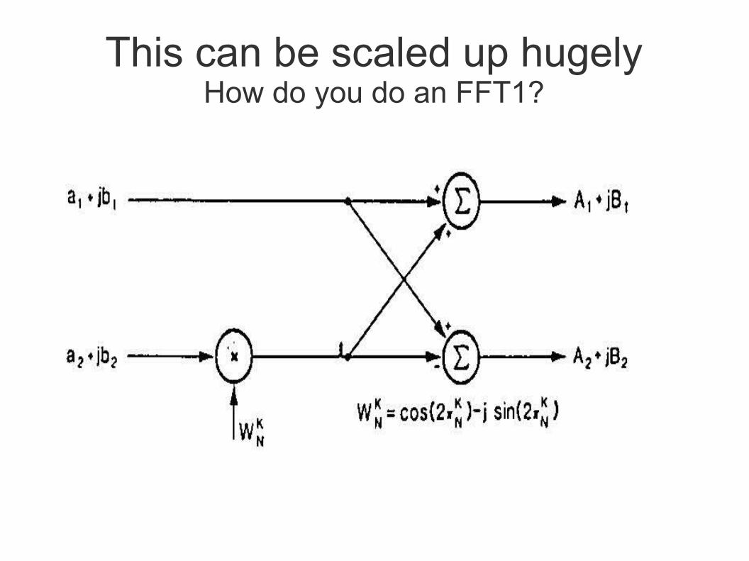
Third method ( Weaver)
Can't quite see it?
What have we covered so far?
● Most of the building blocks of TX and RX in SDR:● IQ demodulators in RX● Need for 16 or 32 bit A/D and fast D/A● Hilbert Transforms● SSB generation by the third method for TX● Doing the signal processing with a DSProcessor● What about doing the signal processing with an
FPGA ( PLA)?

FPGA
● Are used when DSP functions are committed to programmable hardware instead of being software executed by a Digital Signal Processor
● Transceiver functions are selected by I/O port control of the FPGA by a PC. Thus it is Software Defined Radio
● Many architectures: Logic blocks based on LUT ( Xilinx),MUX (Actel),PLA (Altera), Sea of Gates
● Different layouts and interconnection structures

LBLogic Block
LBLogic Block
LBLogic Block
LBLogic Block
LBLogic Block
LBLogic Block
LBLogic Block
LBLogic Block
LBLogic Block
S/Vblock
I/OCell
S/Vblock
I/OCell
S/Vblock
I/OCell
S/Vblock
I/OCell
S/Vblock
I/OCell
S/Vblock
I/OCell
S/V
blo
ckI/O
Cell
S/V
blo
ckI/O
Cell
S/V
blo
ckI/O
Cell
S/V
blo
ckI/O
Cell
S/V
blo
ckI/O
Cell
S/V
blo
ckI/O
Cell
FPGA - Field Programmable Gate Array

LB LB
Row of interconnection resources in a FPGA with architecture
LB LB
LBLB
Long lines over logical blocks
For example, Actel-i Act-1, Act-2 FPGA-d

S
0
1
MUXS
0
1
MUX
S
0
1
MUX
0
0
1
1
X1
X2
X3
X2
X3
Y
Y = X1 X2 + X1 X3
X1 X2 + X1 X3
X3 X2
1 00 1
X1 = 0 X1 = 1
X3 = 0 X3 = 1 X2 = 0 X2 = 1
Example: realisation of function based on MUX-s.
What does what? And where's the PC?
● The recurrence formulae for filters,voice compression,noise limiting, even FFT, Third method ssb, IQ demodulator interpretation etc, etc can all be realized within the logic blocks*
● Which is selected depends on the control of the interconnection busses.
● The PC does the bus control, and most often displays the FFT o/p as a wideband spectrum, and Audio to speaker/earphones
* other functionality splits are possible

Conclusions
● You should now have a feeling for SDR!● Building your own kit will require additional
skills e.g. full understanding of sampled data systems and digital signal processing algorithms plus FPGA or DSProcessor development environments.
● I have investment in a more traditional TXVR can I link to the SDR world?

Conclusions ( cont'd)
● Recent TXVRs like the TS-590 already do a lot of SDR but using an internal processor not a PC! (software updates with improved functionality are regular.)
● Can I link my recent TXVR to a PC for control and extra features like wideband pan-adaptor?● Depends on the rig, but people have started to
devise this. e.g.
http://homepage.ntlworld.com/wadei/HOWTO_TS-590S_with_SDR_IQ.pdf

THE END
Questions...................?