Embed Size (px)
Citation preview

This work is partially supported by the Grant Agency of the Academy of Sciences of the Czech Republic(project number A2030902), the Grant Agency of the Czech Republic (project number 201/99/0244)1
.
SOFTWARE CONNECTORS AND THEIR ROLEIN COMPONENT DEPLOYMENT
Dušan Bálek1, František Plášil1,2
1 Charles University, Faculty of Mathematics and Physics, Department of SoftwareEngineering, Malostranské námstí 25, 118 00 Prague 1, Czech Republic,http://nenya.ms.mff.cuni.cz
2Academy of Sciences of the Czech Republic, Institute of Computer Science, Pod vodárenskouvñí 2, 180 00 Prague 8, Czech Republic, http://www.cs.cas.cz
Abstract To support rapid software evolution, it is desirable to construct software systemsfrom reusable components. In this approach, the architecture of a system isdescribed as a collection of components along with the interactions among thesecomponents. Whereas the main system functional blocks are components, theproperties of the system also strongly depend on the character of the componentinteractions. This fact gave birth to the “connector” concept which is anabstraction capturing the nature of these interactions. The problem tackled in thispaper is that even though the notion of connectors originates in the earliest paperson software architectures [20, 15], connectors are currently far from being atypical first class entity in the contemporary component-based systems.
By articulating the “deployment anomaly”, the paper identifies the role connectorsshould play when the distribution and deployment of a component-basedapplication is considered. Further, we introduce a connector model reflected at allthe key stages of an application’s development: ADL specification, deployment,and implementation
Keywords: Software component, deployment, connector

2 SOFTWARE CONNECTORS AND THEIR ROLE IN COMPONENT
1. INTRODUCTION
A few years ago, the trend to construct software systems as a collection ofcooperating reusable components emerged and has become widely acceptedsince. Influenced by the academic research projects focused on components [8,19, 21, 7, 1, 14, 5], several industrial systems on the market [22, 23, 12, 13, 24]advertise support of component technology. As for components, there is a broadagreement on grasping them as reusable black/grey-box entities with well-defined interfaces and specified behavior. Usually, a component can havemultiple interfaces; some of them to provide services to the component’sclients, other to require services from the surrounding environment.Components can be nested to form hierarchies; a higher-level component canbe composed of several mutually interconnected, cooperating subcomponents.Serving as tools for specifying component interfaces and architecture, a numberarchitecture description languages (ADLs) [8, 21, 1, 14, 17] have beendesigned. To describe component interactions, an ADL may encompass theconnector concept: Typically, a connector is a first class architectural elementthat reflects the specific features of interactions among components in a system[21, 1, 14, 10, 3]. Even though the notion of a connector originates in theearliest papers on software architectures [20, 15], no widespread consensus onhow to incorporate it into the existing application development systems andlanguages has been reached until present.
1.1 Connectors: overview and related work
Studying the related work [8, 21, 1, 3, 14], the following basic approachesto specifying component interactions can be identified: (1) using implicitconnections, (2) via connectors, which can be either built-in or user-defined.
The Darwin language [8] is a typical representative of ADLs that useimplicit connections. The connections among components are specified viadirect bindings of their requires and provides interfaces. The semantics of aconnection is defined by the underlying environment (programming language,operating system, etc.), and the communicating components should be awareof it (to communicate, Darwin components directly use ports of the underlyingRegis environment).
In addition to making system maintenance easier, letting componentscommunicate via connectors has also other significant benefits: increased

SOFTWARE CONNECTORS AND THEIR ROLE IN COMPONENT 3
reusability (the same component can be used in a variety of environments, eachof them providing specific communication primitives) direct support fordistribution, location transparency and mobility of components in a system,support for dynamic changes in the system’s connectivity, etc.
The UniCon language [21] is a representative of ADLs with (only) built-inconnectors. A developer is provided with a selection of several predefinedbuilt-in connector types that correspond to the common communicationprimitives supported by the underlying language or operating system (such asRPC, pipe, etc.). However, the most significant drawback of a UniCon-likeADL is that there is no way to capture any interaction among components thatdoes not correspond to a predefined connector type.
User-defined connectors, the most flexible approach to specifyingcomponent interactions, are employed, e.g., in the Wright language [1]. Theinteractions among components are fully specified by the user (systemdeveloper). Complex interactions can be expressed by nested connector types.However, the main drawback of the Wright language is the absence of anyguidelines as to how to realize connectors in an implementation. (In Wright,connectors exist at the specification level only, which results in the problem ofhow to correctly reflect the specification of a connector in its implementation.)
Based on a thorough study of existing ADLs, Medvidovic et al. [10]presented a classification framework and taxonomy of software connectors.This taxonomy is an important attempt to improve the current level ofunderstanding of what software connectors and their building blocks are. Notaddressing all the issues of designing connector types, it is focused mainly onclassification (thus better comprehension) of connector types. In addition, theselection of basic connector types in [10] may be questionable, as not all ofthem seem to be at the same abstraction level (e.g., adaptor, arbitrator anddistributor vs. procedure call, event, stream).
1.2 Challenges and the goals of the paper
Component-based systems and ADLs have become fields of study in theirown right, however their practical application is still to be demonstrated. Reuseof components is an attractive idea, but the real life has proved many times thatto combine the business components provided by third parties into a runningapplication can be very demanding. The main problem of the current ADLs isthat they either do not capture component interactions at all, or they focus on

4 SOFTWARE CONNECTORS AND THEIR ROLE IN COMPONENT
application design stages only. However, the component interactions have to bereflected throughout the whole application lifecycle, otherwise they maybecome a serious obstacle in component reusability. In particular, thedeployment phase has turned out to be critical in this respect.
The first goal of the paper is to bring an additional argument for consideringconnectors as first class ADL entities by analyzing their role in componentdeployment (deployment anomaly is articulated). The second goal of the paperis to propose a connector model that allows to describe a variety of (possiblycomplex) component interactions, helps system developers target thedeployment anomaly, and at the same time allows to generate the correspondinginteraction code (since none of the existing connector models/ADL systemsprovides a sufficient support for that).
The paper has the following outline. Reviewing the basic ADL concepts forillustration purpose, Section 2 briefly introduces a simple component model andintroduces the deployment anomaly. The set of basic connector tasks andrequirements is identified and studied in Section 3. A new connector model isproposed in Section 4. As a proof of the concept, it is integrated into theSOFA/DCUP component model in Section 5. Finally, the main achievementsand future intentions are summarized in the concluding Section 6.
2. COMPONENTS AND THEIR LIFECYCLE
2.1 A component model
For the purpose of this paper we adopt the following component model(event though based on [16,17] in some details, it very much follows the basicspirit of most ADL languages): An application is viewed as a hierarchy ofsoftware components. A software component is an instance of a componenttemplate (template for short). A template is defined by a pair <componentframe, component architecture>. In principle, the component frame determinesa component type as the set of interfaces provided and required by everyinstance of T (reflecting a black-box view on T's instances). Similarly, thecomponent architecture reflects a gray-box view of each of T’s instances bydescribing its internal structure in the terms of its direct subcomponents andtheir interactions (interface ties, “wiring”). A component architecture can be

SOFTWARE CONNECTORS AND THEIR ROLE IN COMPONENT 5
Figure 1. BankingDemo Architecture
specified as primitive which means that there are no subcomponents and thecomponent frame is directly implemented in the underlying implementationlanguage, for example as a set of Java classes, a shared library, or even a binaryexecutable file. If a component C is an instance of a template with a primitivearchitecture, we say that C is a primitive component, otherwise C is a composedcomponent.
For illustration, consider a bank where tellers serve a number of customers.Each customer requests a teller to perform a desired financial transaction(s) onan account(s). Certain transactions, such as an overdraft, require the teller toask the supervisor for an approval. Each of these entities can be modeled as acomponent (Figure 1). The core of the application is the instance aBank of theBank template (Bank component for short). The Bank component internallycontains an array of Teller subcomponents (T[1], T[2], ... , T[N]), theSupervisor subcomponent, and the DataStore subcomponent. The Bankcomponent features a number of provide interfaces, each of them being tied toa Customer component’s requires interface, and internally tied (delegated) tothe provides interface of a Teller subcomponent. The remaining part of theapplication is formed by the Customer and VisualLogWindow components, thelatter serving for system administration purposes. The communication of theCustomer components with the Bank component is based on procedure calls,while all the interaction with the VisualLogWindow components relies on eventdelivery.

6 SOFTWARE CONNECTORS AND THEIR ROLE IN COMPONENT
Figure 2. Deployment boundaries crossing interface ties
2.2 Component lifecycle
The lifecycle of a component is characterized by a sequence of design time,deployment time, and run time phases (potentially repeated). In a more detailedview, a design time phase is composed of the following design stages:development and provision, assembly, and distribution.
Development and provision. The component is specified at the level ofits template, i.e. component frame and component architecture is specified inan ADL; if the architecture is primitive, its implementation in an underlyingprogramming language/environment has to be also supplied. As a frame F canbe implemented by potentially several component architectures, each of suchtemplates can be viewed as a design version of components of the type F.
Assembly. An application is assembled by choosing one particularcomponent architecture for each frame involved recursively in the topmostframe of the application. Consequently, an executable form of the applicationis based on all the primitive architectures involved recursively in the componentarchitecture associated with the topmost frame.
Distribution. To reflect its future distribution, the assembled applicationis divided into deployment units. Here, two approaches are to be considered: (1)Deployment unit boundaries can cross the component interface ties, but not thecomponent/frame boundaries (Figure 2, right part). Advantageously, thedeployment description of composed/nested components can be done on a top-down basis, following the hierarchy of components. (2) Deployment boundariesare orthogonal to component/frame boundaries. Thus, deployment boundariescan cross a component/frame boundary. Assuming that a primitive componentcannot be distributed (see Deployment below), deployment boundaries cancross a component/frame boundary of compound components only (the

SOFTWARE CONNECTORS AND THEIR ROLE IN COMPONENT 7
alternatives a), c) d) in the left part of Figure 2 are permitted, b) is not). Thusthere is no difference in comparison with (1) when deploying primitivecomponents. As to composed components, the following two problems are noteasy to overcome: (i) the deployment description cannot parallel the hierarchyof component nesting, and (ii) the deployment of a composed component intomore deployments docks (see below) may be a complex process.
Deployment time. The goal is to achieve deployment of the application, i.e.to associate each of its deployment units with a deployment dock and let thesedeployment docks start the application. In principle, a deployment dock servesas a component factory and a container which controls the lifecycle of runningcomponents. A deployment dock may be an instance of Java Virtual Machine,capable to load, instantiate, and run components written in Java, a processescapable to load dynamically linked native libraries and instantiate componentsinto its address space, a daemon that instantiates components by starting newprocesses from binary executables, etc. In such settings, it is natural to requirea primitive component not to be distributed.
2.3 Deployment anomaly
If a deployment unit boundary crosses the interface tie of two componentsA and B, the actual deployment of A and B in general substantially influencesthe communication of A and B. For example, in Figure 3a), the method callson the r and q interfaces have to be modified in order to use an appropriatemiddleware technique of remote procedure calls (RPC), e.g. RMI stub andskeleton is to be employed. These modifications include changes to the internalarchitectures of A and B . Analogously with the inheritance anomaly concept[9, 18], we refer to this kind of a post-design modification of a componentenforced by its deployment as deployment anomaly.
As a quick fix, one can imagine employing an ordinary component DCmediating the communication of A and B (Figure 3 b)). In principle, however,this leads to the deployment anomaly again: (1) If a component DC was addedto handle change in communication enforced by the deployment, the parentcomponent of A and B would be modified by this adjustment of its architecture;(2) As it is unrealistic to imagine a primitive component spanning moredeployment docks, DC has to be a composed component; this leads to the issueof adjusting the internals of some inner components of DC.

8 SOFTWARE CONNECTORS AND THEIR ROLE IN COMPONENT
Figure 3. Deployment anomaly
To illustrate the deployment anomaly on the BankingDemo example,consider the DataStore component is to be deployed in a separate deploymentdock, compared to the rest of the application. Thus, inside the Bank component,all the interactions with DataStore have to be modified to be based on RPC.This post-design modification affects the Teller, Supervisor, and DataStorecomponents.
2.4 Targeting the deployment anomaly: connectors
Basically, the deployment anomaly could be addressed by introducinga firstclass abstraction being: (a) inherently distributed, and (b) flexible enough toaccommodate changes to the component communication enforced by aparticular deployment. The connector abstraction can meet this requirement ifdefined accordingly: (1) It should be a part of the system architecture from thevery beginning (being a first class entity at the same abstraction level as acomponent). (2) To absorb the changes in communication induced by thedeployment modification, a flexible parametrization system of the connectorinternals has to be provided. (3) To reflect inherent distribution, the deploymentof a connector should not be specified explicitly, but inferred from thedeployment description of the components involved in the communication theconnector conveys. As a consequence, the lifecycle of a connector inherentlydiffers from the lifecycle of a component as its underlaying code has to besupplied (e.g. semiautomatically generated) as late as its deployment is known(Section 4.3).
3. BASIC CONNECTOR TASKS
SOFTWARE CONNECTORS AND THEIR ROLE IN COMPONENT 9
To understand the connector concept properly, it is useful to identify andanalyze the basic tasks a connector should perform; here, the taxonomy ofsoftware connectors presented in [10] can be used for guidance. From the mainservice categories and the basic connector types of this taxonomy, we haveselected the connector tasks listed below that we generally consider the keyones. In Section 5, we will show that most of the basic connector tasks can beprovided through a simple hierarchical composition of a few primitiveconnector elements.
Control and data transfer. A connector specifies the mechanisms onwhich possible control and/or data transfer is based (like procedure call, eventhandling, and data stream). Each of these mechanisms has specificcharacteristics and properties, e.g., a procedure call can be local or remote. Asto RPC, various kinds of middleware can be used to implement it. Similarly,event handling can be based on an event channel, a centralized event queue, etc.
Interface adaptation and data conversion. When facing the need to tietwo (or more) components that have not been originally designed tointeroperate, a straightforward idea is to include an adaptor into the connectorabstraction. As mentioned in [16], there is the option (and challenge) to devisea mechanism for automatic or semi-automatic generation of adaptors and/ordata convertors.
Access coordination and synchronization. In principle, the ordering ofmethod calls on a component’s interface is important (the protocol concept in[11]). The permitted orderings are usually determined by a behavioralspecification of the component (e.g., interface, frame and architecture protocolsin SOFA [17], CSP-based glue and computation in Wright). Thus anotherconnector task is access coordination and synchronization - enforcingcompliance with the protocol of an interface (set of interfaces). As an example,consider a server component, implemented for a singe-threaded environment,to be deployed into an environment with multiple client threads. The necessaryserialization of threads can be achieved by a connector mediating the clients’access to the component.
Communication intercepting. Since connectors mediate all interactionsamong components in a system, they provide a natural framework forintercepting component communication (without the participating componentsbeing aware of it) which might help implement various filters (with applicationsin cryptography, data compression, load monitoring, debugging, etc.).

10 SOFTWARE CONNECTORS AND THEIR ROLE IN COMPONENT
4. CONNECTOR MODEL
To reflect the variety of interactions among components in a hierarchicallystructured system, a connector model supporting the creation of a connector bya hierarchical composition of its internal elements is a natural choice. Thiscomplies with the observation that the complexity of interactions amongcomponents depends on the granularity of the system’s architecture description.A finer granularity implies a larger number of components with simplerinteractions, while a coarser granularity implies a smaller number ofcomponents with more complex interactions.
In this section, we propose a connector model designed as follows: Everyinteraction among components in an application is represented by a connectorwhich is an instance of a connector template. Being generic in principle, aconnector template is a pair <connector frame, connector architecture> that canbe parameterized by interface type and property parameters. Given a connectortemplate T, the connector frame specifies the black-box view of a T’s instance(thus it can be referred to as connector type), while the connector architecturespecifies the structure of a T’s instance in terms of its internal elements(primitive elements, component instances, and instances of other connectortemplates) and their interactions (thus it can be referred to as connectorimplementation).
4.1 Connector frame
A connector frame is represented by a set of role instances. In principle, arole is a generic interface of the connector intended to be tied to a componentinterface. In a frame, a role is specified either as a provides role or requiresrole. A provides role serves as an entry point to the component interactionrepresented by the connector template instance and is intended to be tied to a(single) requires interface of a component (or to a requires role of anotherconnector). Similarly, a requires role servers as an outlet point of thecomponent interaction represented by the connector template instance and isintended to be tied to a (single) provides interface of a component (or to aprovides role of another connector). In general, a role is an entity of a genericinterface type; the actual interface type of a role R of a template T is implicitlydetermined by the specific interface (of a component or another connector) tiedto R at the instantiation time of T.

SOFTWARE CONNECTORS AND THEIR ROLE IN COMPONENT 11
Figure 4. Connector model: a) simple architecture, b) compound architecture
4.2 Connector architecture
Depending on the internal elements employed, a connector architecture canbe simple or compound. The internal elements of a simple connectorarchitecture are instances of primitive elements only (Figure 4a); some of themcan be specified as optional. Primitive elements are typed (usually generic typesare employed - both the interface type and property parameters are allowed).For every primitive element type, in addition to functional specification in plainEnglish, a precise specification of its semantics is given by mappings tounderlying environments. For example: “Stub and skeleton elements providethe standard marshaling and unmarshaling functionality of RPC”. Each of theseelements is parameterized by its remote interface type and by the underlyingimplementation platform (specified as a property parameter). The mappings ofthe stub and skeleton element types exist for each of the implementationplatforms supported (CORBA, Java RMI, etc.).
The internal elements of a compound connector architecture are instancesof other connector types and/or components (Figure 4b). This concept allowsfor creating complex connectors with hierarchically structured architecturesreflecting the hierarchical nature of component interactions. For examples, werefer the reader to Sections 5.1 and 5.2.
4.3 Connector lifecycle
The connector lifecycle substantially differs form the component lifecycle.It can be viewed as a sequence of the design time, instantiation time,deployment and generation time, and runtime phases.

12 SOFTWARE CONNECTORS AND THEIR ROLE IN COMPONENT
Connector design. The connector is specified as a template in ADL. Foreach of its primitive element types, a functional specification and definition ofcorresponding mappings (at least one) are to be provided. Since connectors areinherently distributed entities, the connector architecture is divided into anumber of disjoint deployment units. A deployment unit is formed by the roleinstances and internal elements designed to share the same deployment dock.
Connector instantiation. The connector is instantiated within anapplication. Since the actual interface types of the entities tied by the connectorinstance become known at this point, the interface type parameters of theconnector’s roles can be resolved. Also the actual need for some of thoseprimitive elements specified as optional at the design time (e.g. interfaceadaptors) reveals. A part of the connector instance remains generic - due to theunresolved property parameters related to a future deployment of the connector.
Connector deployment and generation. Connectors are deployed at thesame time as the components the interactions of which they convey. To each ofthe connector’s deployment units, a specific deployment dock is assigned. Fora connector of simple architecture, the actual deployment docks of theconnector’s deployment units can be inferred from the locations of thecomponents interconnected by the connector. The deployment of potentialinternal components of a connector is specified in the same way as thedeployment of “ordinary” components in the application.
Once the deployment of a connector is known, the connector’simplementation code is (semi-automatically) generated to use thecommunication primitives offered by the deployment docks’s underlyingenvironments. Note that the generated code of the primitive elements eitherfollows their mapping to the underlying programming environment, or it can benull (e.g., no need for an adaptor). Note that the connectors with primitivearchitectures are considered for code generation while the connectors ofcompound architectures are created by composition of their internal elements.
A typical scenario of the code generation of a connector is as follows: (1)Using a deployment tool, the deployment of components (the interaction ofwhich the connector conveys) is specified. (2) Each of the selected deploymentdocks is then asked to automatically generate the implementation code of thoseinternal elements of the connector that are intended to be deployed in it. (3) Thedeployment dock replies the list of technologies offered by its underlyingenvironment on which the generated implementation could be based (the
SOFTWARE CONNECTORS AND THEIR ROLE IN COMPONENT 13
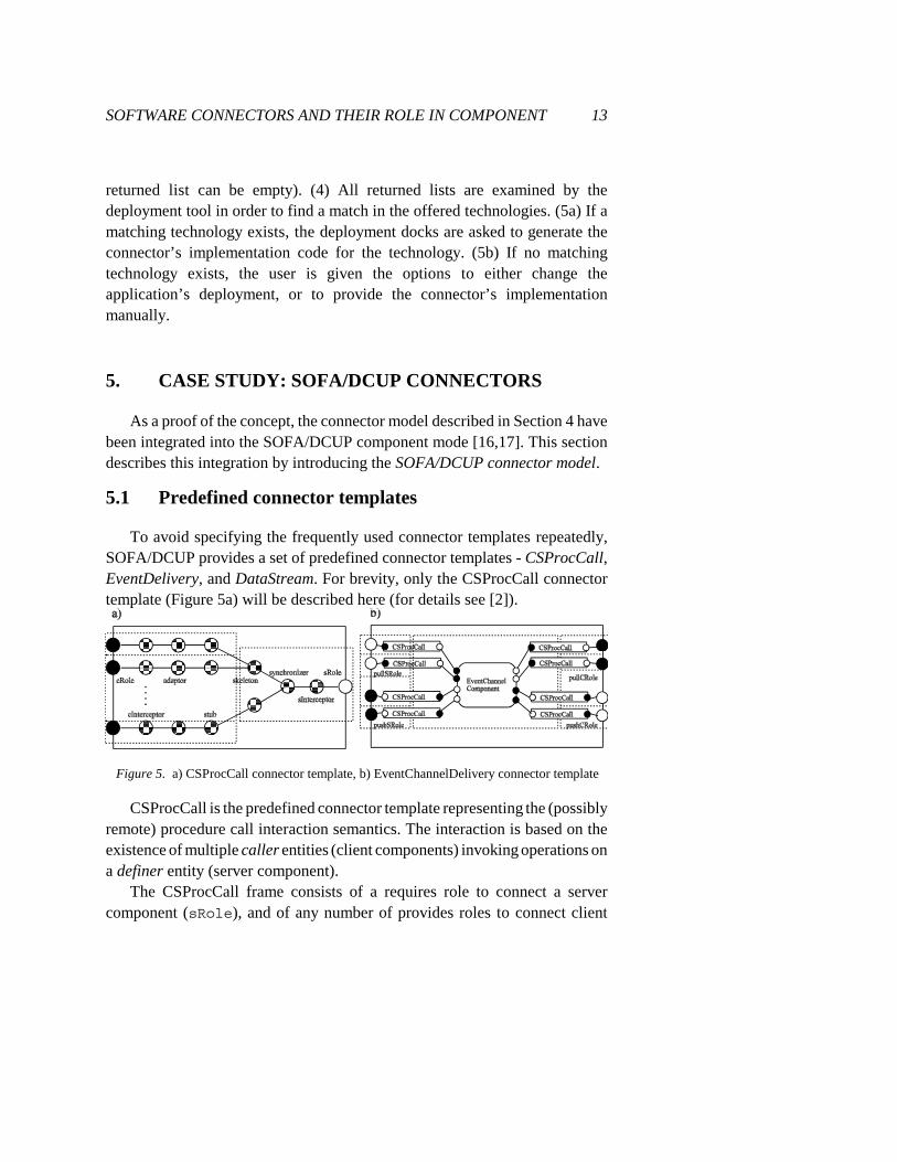
Figure 5. a) CSProcCall connector template, b) EventChannelDelivery connector template
returned list can be empty). (4) All returned lists are examined by thedeployment tool in order to find a match in the offered technologies. (5a) If amatching technology exists, the deployment docks are asked to generate theconnector’s implementation code for the technology. (5b) If no matchingtechnology exists, the user is given the options to either change theapplication’s deployment, or to provide the connector’s implementationmanually.
5. CASE STUDY: SOFA/DCUP CONNECTORS
As a proof of the concept, the connector model described in Section 4 havebeen integrated into the SOFA/DCUP component mode [16,17]. This sectiondescribes this integration by introducing the SOFA/DCUP connector model.
5.1 Predefined connector templates
To avoid specifying the frequently used connector templates repeatedly,SOFA/DCUP provides a set of predefined connector templates - CSProcCall,EventDelivery, and DataStream. For brevity, only the CSProcCall connectortemplate (Figure 5a) will be described here (for details see [2]).
CSProcCall is the predefined connector template representing the (possiblyremote) procedure call interaction semantics. The interaction is based on theexistence of multiple caller entities (client components) invoking operations ona definer entity (server component).
The CSProcCall frame consists of a requires role to connect a servercomponent (sRole), and of any number of provides roles to connect client

14 SOFTWARE CONNECTORS AND THEIR ROLE IN COMPONENT
components (cRole). All of the roles are generic entities with interface typeparameters.
The CSProcCall architecture is simple. It consists of several primitiveelements interconnected in the way illustrated in Figure 5a). ThecInterceptor and sInterceptor instances of TInterceptor provide aframework for plugging in an additional connector functionality to supportlogging, debugging, etc. An interface adaptor is (optionally) included in aconnector instance if a particular client’s interface does not match the serverinterface. A (TStub, TSkeleton) instance pair is used if a remote invocationis needed. These primitive elements provide the standard RPC marhalling andunmarshalling. A synchronizer is (optionally) included if the servercomponent requires client invocations to be synchronized when accessing itsinterface.
There is an exactly one server deployment unit (composed of sRole,sInterceptor, synchronizer, and skeleton) and any number of clientdeployment units (each of them composed of cRole, cInterceptor,adaptor, and a stub). There is one client deployment unit per connectedclient component.
The following fragment of source text illustrates the main parts of theCSProcCall specification using the modified SOFA CDL notation.
connector frame CSProcCall<CT, ST> (Properties properties){provides: optional multiple Role<CT> Crole;requires: Role<ST> Srole;
};connector architecture CSProcCall {
inst optional multiple TInterceptor<CT> cInterceptor;inst optional multiple TAdaptor<CT, ST> adaptor;inst optional multiple TStub<ST> stub;inst optional multiple TSkeleton<ST> skeleton;inst optional TSynchronizer<ST> synchronizer;inst optional TInterceptor<ST> sInterceptor;delegate cRole to cInterceptor;bind cInterceptor to adaptor;bind adaptor to stub;bind stub to skeleton;bind skeleton to synchronizer;bind synchronizer to sInterceptor;subsume sInteceptor to sRole;
};

SOFTWARE CONNECTORS AND THEIR ROLE IN COMPONENT 15
5.2 User-defined connector templates
The process of creating a new connector template can be illustrated on theexample of EventChannelDelivery, a connector template reflecting event-basedcommunication via an event channel. Similarly to the CORBA Event Service,this connector template allows multiple suppliers to send data asynchronouslyto multiple consumers in both the push and pull modes.
The EventChannelDelivery frame consists of a number of roles to connectsupplier components in the push and pull modes (pushSRole andpullSRole), and of a number of roles to connect consumer components in thepush and pull modes (pushCRole andpullCRole). All of the roles are genericentities with interface type parameters.
The EventChannelDelivery architecture is compound. As depicted in Figure5b), the core element of the EventChannelDelivery architecture is an instanceof the EventChannel component. The other internal elements ofEventChannelDelivery are instances of the CSProcCall connector template totie EventChannelDelivery’s roles to the EventChannel’s interfaces.
The division into deployment units is illustrated in Figure 5b). It should beemphasized that while the deployment of the internal CSProcCall connectorsis partially determined by the EventChannelDelivery’s roles, the deploymentof the EventChannel component (and related parts of CSPracCall connectors)has to be stated explicitly as with “ordinary” components.
5.3 Using SOFA/DCUP connectors
To demonstrate how the SOFA/DCUP connectors can be used, consider theDataStore and Supervisor components from the banking application introducedin Section 2.1. The following fragment of CDL specification illustrates theirinterconnection using the CSProcCall connector instance.
inst DataStore DS;inst Supervisor Sup;bind Sup.dsi to DS.dsi using CSProcCall;
Since the actual interfaces of the DataStore and Supervisor components areknown at this point, the interface type parameters of the conveying connectorare resolved. Assuming that the actual interfaces match, the interface adaptor
16 SOFTWARE CONNECTORS AND THEIR ROLE IN COMPONENT
(as an optional element of the CSProcCall architecture) will be omitted.However, the rest of the connector architecture still remains generic due to theunresolved property parameters related to future deployments of theapplication.
Consider a deployment scenario which assumes that the DataStore andSupervisor components are to be deployed into separate deployment docks.Since both components do not share an address space, a cross-address spacecommunication is needed. The stub and skeleton internal elements are thereforegenerated and included in the resulting connector.
6. EVALUATION AND CONCLUSION
As the first goal of the paper, we articulated the deployment anomaly as thenecessity for a post-design modification of components caused by theirparticular deployment. This is a serious obstacle in usingcomponent-based real-life applications. In a practical setting, the deployment of a component - basedapplication can be efficiently done by system staff members, experts in theunderlying system environment (typically in the brands of middleware to beemployed). To realize the necessary deployment modifications, these peoplewould have to study the business logic details of the components subject to thedeployment. This is inherently inefficient, if not even impossible, since someof the components may be of a third-party origin. A symmetrical inefficiencywould be to ask the business logic designers to deal with the localnetworking/middleware details. For these reasons it is very desirable to separatethe business and communication part of the component - based application.This issue can be addressed by the connector concept presented in the paper .
None of the current ADL languages/systems, such as [14, 19, 7, 21, 1],targets the deployment issue directly nor combines it with connectors). Thesecond goal of the paper was therefore to propose a novel connector modelallowing not only to express and represent a variety of possible interactionsamong components in an application at all key stages of the applicationlifecycle, but in particular to reflect component distribution.
In summary, in the presented component model, the key differencebetween a component and connector is in (1) distribution (a primitiveconnector can be distributed, while primitive component cannot) and (2) in the

SOFTWARE CONNECTORS AND THEIR ROLE IN COMPONENT 17
lifecycle (parts of the connector can be generated only after all componentdeployment has been determined). In addressing the deployment anomaly, aconnector helps in (3) separation of concerns (by separating the business andcommunication part of a component-based application), and in (4) reusability -if the primitive elements are designed properly, they can be reused in many ofthe typical component communication patterns. The important trick supportingthe reusability is that the primitive elements are very generic (work almost for“any interface”); the modification of the communication pattern for the actualinterfaces is done in an automatized way, i.e. it can be generated.
Having finished a pilot implementation of our connector model, wecurrently focus on finding techniques for at least semi-automatic generation ofprimitive elements, including interface adaptors, stubs and skeletons for remotecommunication, etc. We believe this can be done by defining a mapping ofevery primitive element type to the underlying programming environment.Another future intention is to apply behavioral protocols [17] in connectorspecification to express the interplay of its internal elements.
REFERENCES
[1] Allen, R. J.: A Formal Approach to Software Architecture. Ph.D. Thesis, School of ComputerScience, Carnegie Mellon University, Pittsburgh, 1997.
[2] Balek, D., Plasil, F.: A Hierarchical Model of Software Connectors, Tech. Report No. 2000/2,Department of SW Engineering, Charles University, Prague, 2000.
[3] Bishop, J., Faria, R.: Connectors in Configuration Programming Languages: are TheyNecessary? Proceedings of the 3rd International Conference on Configurable Distributed Systems,1996.
[4] Ducasse, S., Richner, T.: Executable Connectors: Towards Reusable Design Elements. InProceedings of ESEC/FSE’97, Lecture Notes in Computer Science no. 1301, Springer-Verlag,1997.
[5] Issarny, V., Bidan, C., Saridakis, T.: Achieving Middleware Customization in aConfiguration-Based Development Environment: Experience with the Aster Prototype. InProceedings of ICCDS ‘98, 1998, http://www.irisa.fr/solidor/work/aster.html.
[6] Leavens, G.T., Sitaraman,M.(eds.): Fundations of Component-Based Systems, CambridgeUniversity Press 2000.
[7] Luckham,D. C., Kenney, J. J., Augustin, L. M., Vera, J., Bryan, D., Mann, W.: Specificationand Analysis of System Architecture Using Rapide. IEEE Transactions on Software Engineering},21(4), 1995.

18 SOFTWARE CONNECTORS AND THEIR ROLE IN COMPONENT
[8] Magee, J., Dulay, N., Kramer, J.: Regis: A Constructive Development Environment forDistributed Programs. In Distributed Systems Engineering Journal, 1(5), 1994.
[9] Matsuoka, S., Yonezawa, A.: Analysis of Inheritance Anomaly in Object-Oriented ConcurentProgramming Languages. Research Directions in Concurrent Object-Oriented Programming, MITPress, 1993.
[10] Mehta N. R., Medvidovic, N.,Phadke S.: Towards a Taxonomy of Software Connectors. InProceedings of the 22th International Conference on Software Engineering (ICSE 2000), Limerick,Ireland, 2000.
[11] Nierstrasz, O.: Regular Types for Active Objects, In Proceedings of the OOPSLA ‘93, ACMPress, 1993, pp. 1–15.
[12] OMG orbos/99-04-16, CORBA Component Model. Volume 1, 1999.
[13] OMG orbos/99-04-17, CORBA Component Model, Volume 2, 1999.
[14] Oreizy, P., Rosenblum, D. S., Taylor, R. N.: On the Role of Connectors in Modeling andImplementing Software Architectures, Technical Report UCI-ICS-98-04, UniversityofCalifornia,Irvine, 1998.
[15] Perry, D.E., Wolf, A. L.: Foundations for the Study of Software Architecture. ACM SoftwareEngineering Notes, vol. 17, no. 4, 1992.
[16] Plasil, F., Balek, D., Janecek, R.: SOFA/DCUP Architecture for Component Trading andDynamic Updating. In Proceedings of ICCDS '98, Annapolis, IEEE CS, 1998, pp. 43–52.
[17] Plasil, F., Besta, M., Visnovsky, S.: Bounding Component Behavior via Protocols. InProceedings of TOOLS USA ‘99, Santa Barbara, USA, 1999.
[18] Plasil, F., Mikusik, D.: Inheriting Synchronization Protocols via Sound Enrichment Rules.In Proceedings of JMPLC, Springer LNCS 1204, March 1997.
[19] Purtilo, J. M.: The Polylith Software Bus. ACM Transactions on Programming Languagesand Systems, 16(1), 1994.
[20] Shaw, M.: Procedure Calls Are the Assembly Language of Software Interconnection:Connectors Deserve First-Class Status. In D.A. Lamb (ed) Studies of Software Design,Proceedings of a 1993 Workshop, Lecture Notes in Computer Science no. 1078, Springer-Verlag1996.
[21] Shaw, M., DeLine, R., Klein, D. V., Ross, T. L., Young, D. M., Zalesnik, G.: Abstractionsfor Software Architecture and Tools to Support Them. IEEE Transactions on SoftwareEngineering, Vol. 21, No. 4, April 1995, pp. 314–335.
[22] Sun Microsystems: JavaBeans 1.0 Specification. http://java.sun.com/beans/docs/spec.html.
[ 2 3 ] Su n Micro sys tems : En te rp r i se JavaB e a n s 1 . 1 S p e c i f i c a t i o n .http://java.sun.com/products/ejb/docs.html.
[24] Rogerson, D.: Inside COM. Microsoft Press 1997.
[25] Yellin, D. M., Strom, R. E.: Interfaces, Protocols, and the Semi-Automatic Construction OfSoftware Adaptors. In Proceedings of the OOPSLA ‘94, ACM Press, 1994, pp. 176–190.