Embed Size (px)
Citation preview
Software Architectures for Correct Components Assembly
Paola Inverardi
Dipartimento di Informatica
Universita’ dell’Aquila

Several people contributed to the general issue …
Alexander Wolf Daniel Yankelevich Sebastian Uchitel Simone Scriboni Massimo Tivoli

Presentation Scheme Introduction Motivation Software Architectures and Component-based
systems Our Approach
Without a fixed Software Architecture Infrastructure Assumptions Partial Equivalence
The role of fixed Software Architecture Synthesis
Conclusions + Future Work

We believe that…
Model construction should be part of the development process. Early identification of problems.
Analysis by model checking. Increased confidence on the adequacy and validity of the final
product. Mechanical verification of properties.
In particular: Design of concurrent systems. Integration of components can introduce interaction problems
that are hard to detect. Deadlock, starvation, safety and liveness properties.
Motivation
In some cases existing model checking techniques can be too expensive to be applied successfully.State explosion problem.Techniques developed to accommodate a
very broad range of concurrent systems.

The role of Software Architecture Very high level system abstraction
Component and connectors
Architectural Properties
Does this help in managing verification problems?

A bit of history: CP
3
Compressing HTTP Proxy (CP)
Adaptor(Pseudo Filter)
Filter Filter
GZIP
function-call interface
UNIX pipe interface
UNIX process
component
channel 1 2
3 41
32
4

CP: HTTP to improve the performance of UNIX-based WWW browsers by Garlan, Kindred, and Wing 1995.
compresses and uncompresses data across the network by using gzip compression/decompression program together with standard HTTP servers .
To assemble the Compressing Proxy from HTTP servers and gzip, use an adaptor to manage interfaces
The adaptor acts as a pseudo CERN HTTP filter, communicating with the upstream and downstream filters through a function-call interface, and with gzip using pipes connected to a separate gzip process.
CP components behavior
the upstream filter offers data along channel 1 (to AD and the downstream filter accept data along channel 4 (from AD).
GZ accepts data along channel 2 (from AD). It can then end its input and start offering data along channel 3 (to AD), and then end.
AD accepts data along channel 1 (from an upstream
filter) and must wait until it has stopped accepting the data before it can offer data on channel 2 (to GZ).It can then end its output.
Verification: 2 deadlocks
the adaptor and gzip reach a state in which one is willing to output on channel 2 while the other is willing to output on channel 3. Both components are trying to output.
Both the adaptor and gzip are trying to input, one on channel 3 and the other on channel 2.

How do we verify CP SA?
We build the complete model of the 4 components (automata)
Model check to find deadlocks
Could have we been smarter?
Fine but …

Component-based systems
Component-based systems (CBS).Growing acceptance in industry.Characteristics of concurrent systems.
Can new (and more efficient) model checking techniques be developed in the context of CBS?
Component-based software development
Focuses on building large software systems by integrating previously-existing software components [SEI-CMU].
Embodies the "buy, don't build" philosophy [Brooks 87]. Boosted by…
Increase in the quality and variety of Commercial Off-The-Shelf (COTS) components.
Component integration technologies. E.g. COM & CORBA Lower development and maintenance budgets.
Introduces a new approach to system design
Designing component-based systems
Components are… autonomous, decoupled, concurrent and possibly
distributed entities. with well defined interfaces for communication and
synchronisation.
Integration context provides… abstraction framework for integrating components.
E.g. network, operating system, data representation… standard services: naming, yellow pages,… capabilities for accessing component services.
Only simple interactions are supported. For example: In CORBA only 3: Synchronous, Deferred
Synchronous and One Way
Checking Deadlock Freedom in CBS
Can we take advantage of… Simple interaction mechanisms. Flat architecture.
… in CBS to check for deadlock freedom? YES
How? Our approach is based on… Extra information at component level: Assumptions. Tightly coupled with: property and architecture. Local checks. E.i. component to component.
Results: Efficient but incomplete deadlock detection.

Modelling Component behaviour modelled using finite state
machines. Integration through parallel composition of
component models. In the context of CCS
Components: sequence and choice operators.E.g. Server = call.service.return.Server.
Integration: parallel composition and restriction operators.
E.g. (C1 | C2 | ... | Cn) / L
Deadlock: (C1 | C2 | ... | Cn) / L can reach a state where no actions are possible.

Assumptions
Component requirement on its environment in order to guarantee a property in a specific integration context.
In a sense we are enhancing component semantics.
In our case we use: “My context never blocks me” or in other words “If I can perform action a, my context must be able to perform action a”.
Assumptions modeled in the same way as components.

Back to CP
3
Compressing HTTP Proxy (CP)
Adaptor(Pseudo Filter)
Filter Filter
GZIP
function-call interface
UNIX pipe interface
UNIX process
component
channel 1 2
3 41
32
4
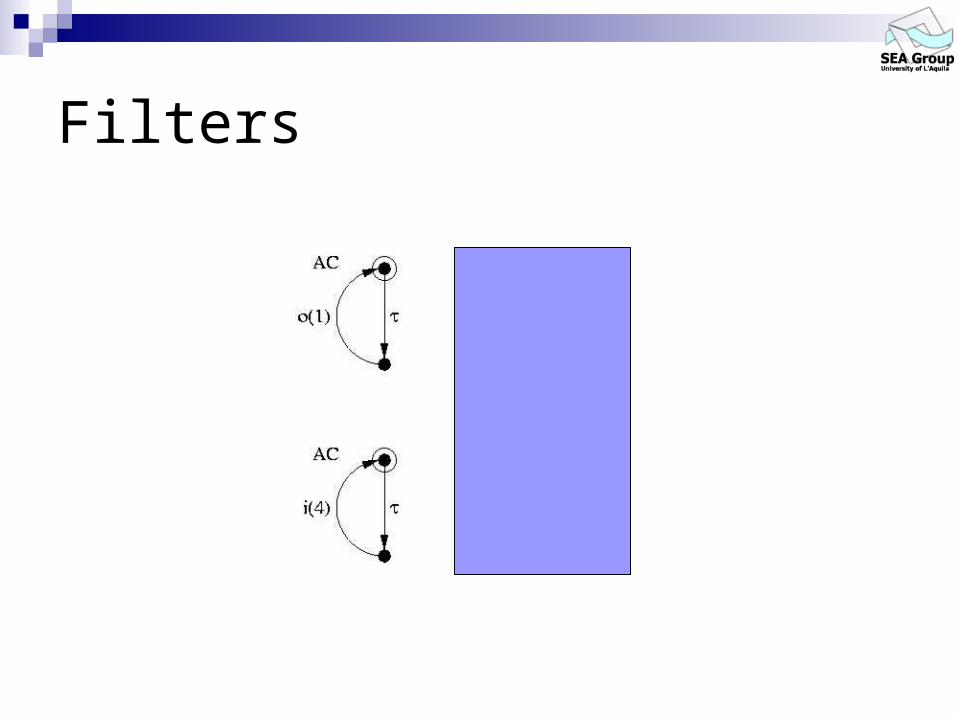
Filters

GZIP

Adaptor

Relation between component assumptions and behaviours.
Compare assumptions with context. Based on observational equivalence…
A B: If A can do action a then B can also do a and continue to be observationally equivalent to A.
and allows partial matching…
Partial Equivalence
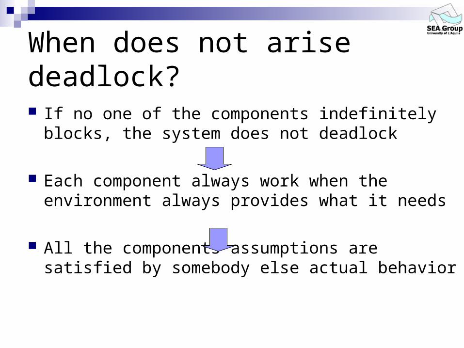
When does not arise deadlock?
If no one of the components indefinitely blocks, the system does not deadlock
Each component always work when the environment always provides what it needs
All the components assumptions are satisfied by somebody else actual behavior

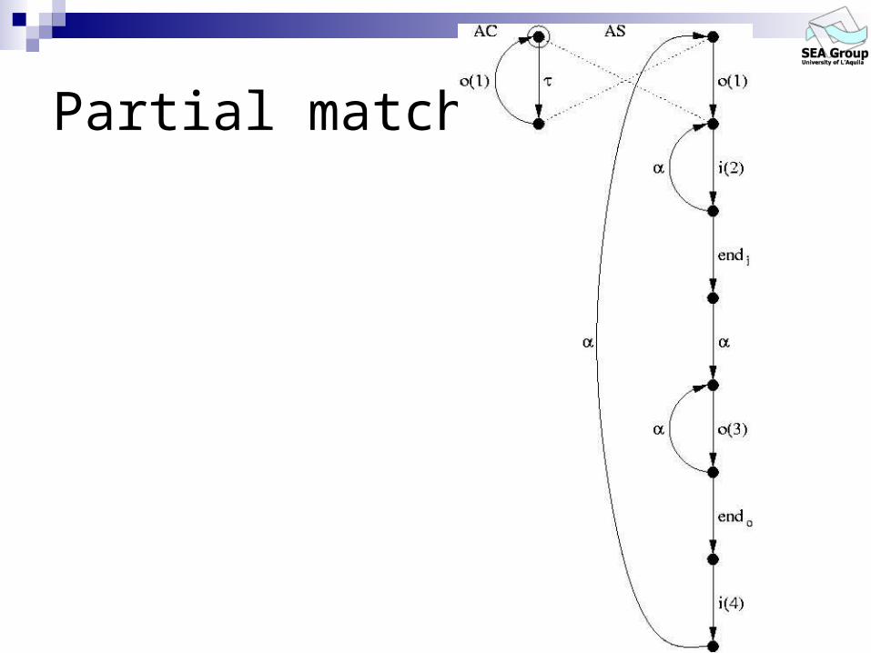
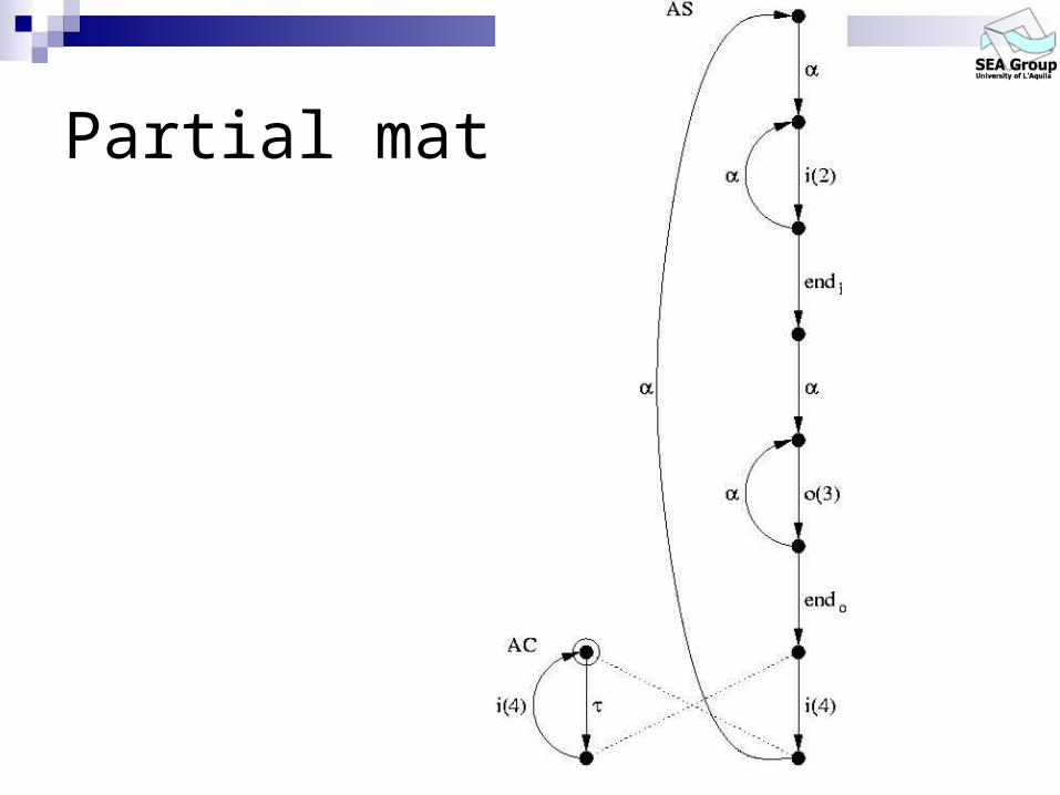
Partial Equivalence
Requires behaviours to be equivalent up to a set of stopping nodes. A B: If A can do action a then B can also do a
and always continues to be observationally equivalent to A up to a certain set of stopping states.
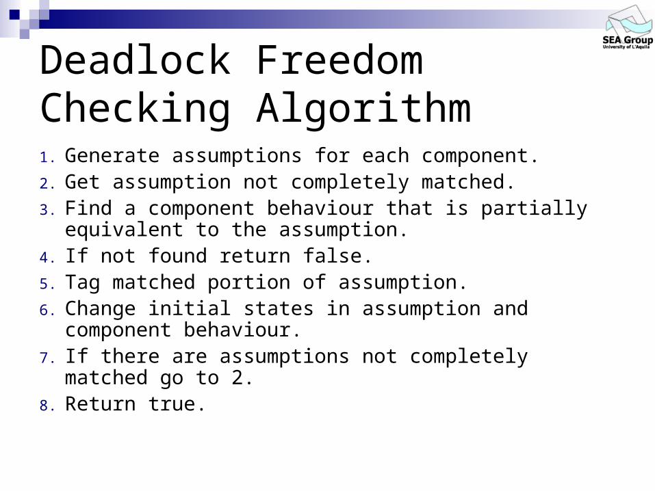
Deadlock Freedom Checking Algorithm1. Generate assumptions for each component.2. Get assumption not completely matched.3. Find a component behaviour that is partially equivalent to
the assumption.4. If not found return false.5. Tag matched portion of assumption.6. Change initial states in assumption and component
behaviour.7. If there are assumptions not completely matched go to 2.8. Return true.
Partial match
Partial match

Partial match

call return call
return
output
restart
output
service
ServerActual Behaviour
ClientAssumed Behaviour
Successful Matching
Stopping nodes

Successful Matching (II)
return
return
output
restart
call output
service
ServerActual Behaviour
ClientAssumed Behaviour

New Adaptor

New match 1

New match 2
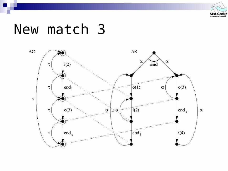
New match 3
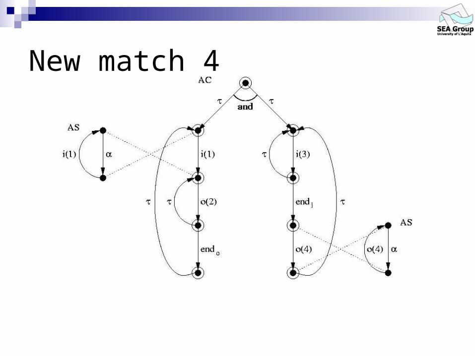
New match 4
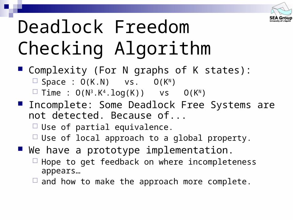
Deadlock Freedom Checking Algorithm Complexity (For N graphs of K states):
Space : O(K.N) vs. O(KN) Time : O(N3.K4.log(K)) vs O(KN)
Incomplete: Some Deadlock Free Systems are not detected. Because of... Use of partial equivalence. Use of local approach to a global property.
We have a prototype implementation. Hope to get feedback on where incompleteness appears… and how to make the approach more complete.

What can we conclude?
Deadlock freedom checking algorithm that… has very good space complexity and comparable time
complexity. is incomplete.
The concept of assumptions as an extension to component semantics.
Framework that might be extendable to other properties and integration contexts.

So far so good but … We have modelled AC and AS component
behaviors We do not have hypothesis on the SA, i.e. on the
interaction infrastructure We are able to efficiently capture some behavioral
problems
Can we do better?

Let us re-consider the problem
software projects are based on the integration of COTS components.
Integration frameworks are fixed: CORBA, COM/DCOM, etc.
Component based technologies provide composition mechanisms

What is the problem?
The ability to establish properties on the assembly code by only assuming a relative knowledge of the single components properties.
A software architecture represents the reference skeleton used to compose components and let them interact:
interactions among components are represented by the notion of software connector.

What would we like to do:
extend the analysis of component-based systems to general safety and liveness properties;
provide recovery strategies besides property analysis; (e.g.: avoid deadlock, starvation and guarantee safety and liveness)
make the whole approach as automatic as possible;
validate the approach on several concrete component-based architectural models.

Problem description
Given a set of components C and a set of properties P automatically derive an assembly A of these components which satisfies every property in P.
Basic ingredients: the type of components we refer to (COTS, black-box); the type of properties we want to check (functional,
interaction behaviors); the type of systems we want to build (component-based).
Basic idea A simple software architecture structure which
exploits the separation between functional behavior and Integration/Communication behavior.
Extra information at component level: component actual behavior and assumptions.
Our approach: detect software anomalies; remove software anomalies; guarantee a given coordination policy.
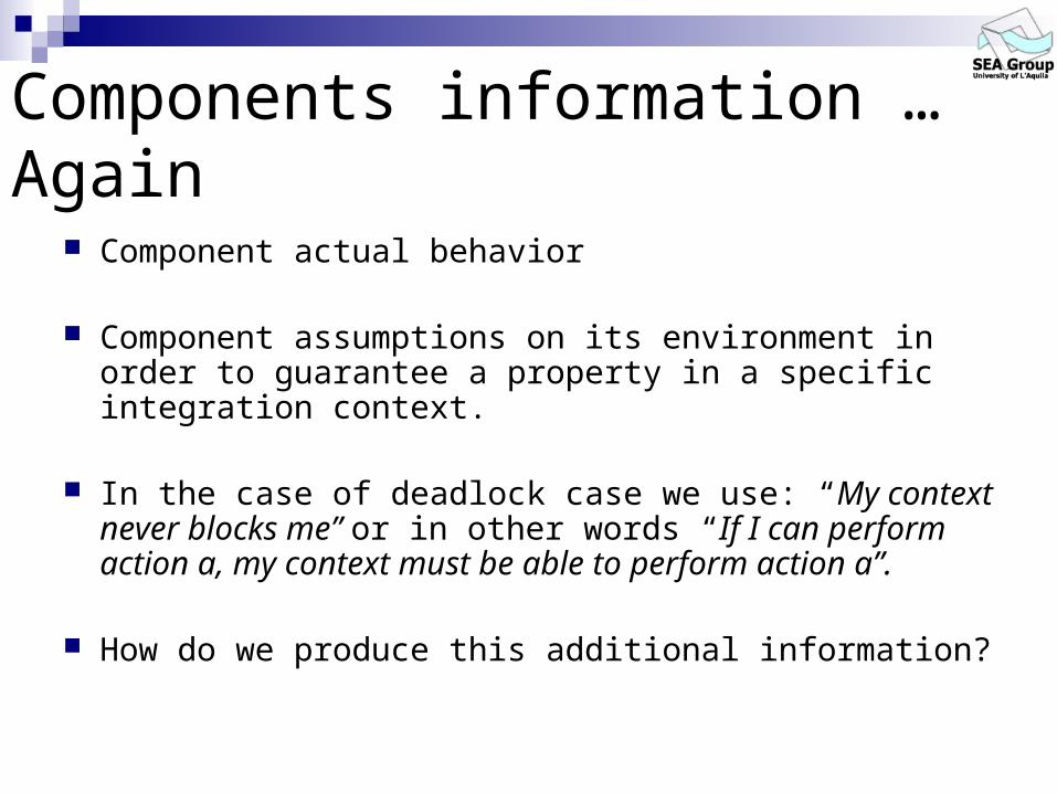
Components information …Again
Component actual behavior
Component assumptions on its environment in order to guarantee a property in a specific integration context.
In the case of deadlock case we use: “My context never blocks me” or in other words “If I can perform action a, my context must be able to perform action a”.
How do we produce this additional information?

Modeling the system Partial behavioural specification of the composed
system: bMSCs (basic Message Sequence Charts)
a bMSC describes a single scenario as a set of finite interactions between a set of components;
HMSCs (High-level Message Sequence Charts) a HMSC provides the means for composing bMSCs as a directed
graph where nodes represent bMSCs and edges indicate their possible continuations.
Specification of the behavioural properties to be enforced: LTL (Linear-time Temporal Logic)
is a formalism for describing sequences of transitions between states in reactive system;
operators are provided for describing events along a single computation path.

Modeling … continuing Component behaviour modelled using finite state machines:
finite-state CCS (Calculus of Communicating Systems); LTS (Labelled Transitions System).
Integration through parallel composition of component models.
In the context of CCS Components: prefix and choice operators.
E.g. ServerA = (call_service1.return1 + call_service2.return2).ServerA
Integration: parallel composition and restriction operators. E.g. (C1 | C2 | ... | Cn) / L
Deadlock: (C1 | C2 | ... | Cn) / L can reach a state where no actions are possible.

Connector Free Architecture
Component 1
Component 2 channel
Component 3
channel
A Connector Free Architecture (CFA) is a set ofcomponents directly connected in a synchronous way.
In CCS : (C1 | C2 | ... | Cn) \ Ui=1..n Acti
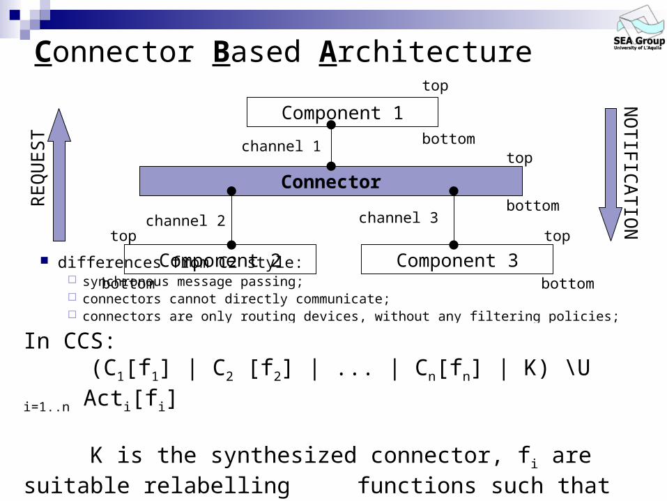
Connector Based Architecture
differences from C2 style: synchronous message passing; connectors cannot directly communicate; connectors are only routing devices, without any filtering policies; connectors have a strictly sequential input-output behavior.
RE
QU
ES
TN
OT
IFIC
AT
ION
Connectortop
bottom
Component 1
top
bottomchannel 1
Component 2
top
bottom
channel 2
Component 3
top
bottom
channel 3
In CCS:(C1[f1] | C2 [f2] | ... | Cn[fn] | K) \U i=1..n Acti[fi]
K is the synthesized connector, fi are suitable relabelling functions such that fi()=i, for all Acti

Approach description: 3-step method
Component 1 Component 3
Component 2
Connector Free Architecture
Connector Based Architecture
Component 1 Component 3
Component 2
Connector
local views of each component
deadlock-freeness
Component 1
Deadlock-free Connector Based Architecture
Component 3
Component 2
Deadlock-free Connector Behavioral property
Component 1
Failures-free Connector Based Architecture
Component 3
Component 2
Failure-free ConnectorConnector code(assembly code)

Example A client/server (single-layer) system:
2 clients (C1, C2); 1 server (C3).
C1 C2 C3a
b
S1
bMSCs:
S1 S2
HMSC:
C1 C2 C3c
d
a
S2
sLbl1=S1
sLbl2=S2 sLbl3=S3
sLbl1=S’1sLbl2=S2 sLbl3=S’3
sLbl1=S1
sLbl2=S2 sLbl3=S3
sLbl1=S1 sLbl2=S2sLbl3=S3
sLbl1=S1 sLbl2=S’2 sLbl3=S’’3
sLbl1=S1 sLbl2=S’’2 sLbl3=S’’’3
sLbl1=S1 sLbl2=S2sLbl3=S3
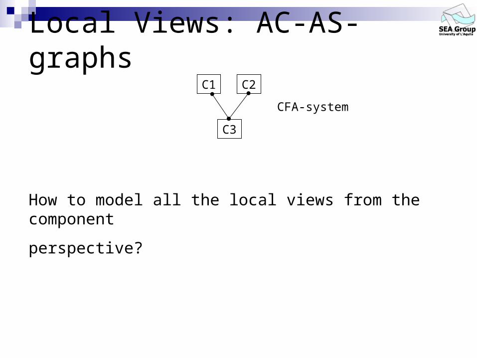
Local Views: AC-AS- graphsC1 C2
C3
CFA-system
How to model all the local views from the component
perspective?

Example: AC-AS- graphs
Knowing the composition mechanism
AS: assumptions on the environment AS1: c
a
db a
S1
SI1
S2
SI2
SII2
S3
SII3
SIII3
c
a
d
SI3
abAS2: AS3:
AC: the inner knowledgeAC1: c
a
db a
S1
SI1
S2
SI2
SII2
S3
SII3
SIII3
c
a
d
SI3
abAC2: AC3:

If we know the SA …EX- graphs
C1 C2
C3
K1 2
3CBA-system
Knowing the characteristics of the connector, i.e. the environment
EX: assumptions on the connector
EX1: c2
a2
d?b1
a1
S1
SI1
S2
SI2
SII2
EX2: EX3:
a?
b?
S1
SI1
c?
a?
d2
S2 SI2
SII2
c?
a?
d3S3
SII3
c3
a3
d?
S3SII
3
SIII3
SIII3
b3
a3
b?
a?
S3SI
3
SI3

Example: EX-Graphs unification (first step)
K: c2 a2
d3K1
K5c3
a3
d2
K4
K9
K10K11
b3
a3
b1
a1
K2K3
K6
K7K8
nodes labels:
a1 a3
K1=<S1,S2,S3>
K2=<S1,S2,S3>K3=<SI
1,S2,SI3>
K4=<S1,S2,S3>
K5=<S1,SI2,S
II3>
K6=<SI1,S2,S
I3>
K7=<S1,SI2,S
II3>
K8=<SI1,S
I2,S
III3>
K9=<S1,SI2,S
II3>
K10=<S1,SII
2,SIII
3>
K11=<S1,SII
2,SIII
3>
is based on a usual first-order unification algorithm
EX1: c2
a2
d?b1
a1
S1
SI1
S2
SI2
SII2
EX2: EX3:
a?
b?
S1
SI1
c?
a?
d2
S2 SI2
SII2
c?
a?
d3S3
SII3
c3
a3
d?
S3SII
3
SIII3
SIII3
b3
a3
b?
a?
S3SI
3
SI3

Deadlock recovery (second step) It is enough to prune all the finite branches of
the connector transition graph.
A further check: the portion of the connector graph related with the
communication with Ci has to CB-simulate the AS-Graph ASi.
CB-simulation is a notion of “state-based” equivalence.
We cannot solve behavioral failures that are not identifiable with precise behaviors of the synthesized connector (black-box setting).

Example: deadlock recovery (second step)
K: c2 a2
d3K1
K5c3
a3
d2
K4
K9
K10K11
b3
a3
b1
a1
K2K3
K6
K7K8
nodes labels:
a1 a3
K1=<S1,S2,S3>
K2=<S1,S2,S3>K3=<SI
1,S2,SI3>
K4=<S1,S2,S3>
K5=<S1,SI2,S
II3>
K6=<SI1,S2,S
I3>
K7=<S1,SI2,S
II3>
K8=<SI1,S
I2,S
III3>
K9=<S1,SI2,S
II3>
K10=<S1,SII
2,SIII
3>
K11=<S1,SII
2,SIII
3>
AS1: c
a
db a
S1
SI1
S2
SI2
SII2
S3
SII3
SIII3
c
a
d
SI3
abAS2: AS3:
a
b
<=CB
<=CB
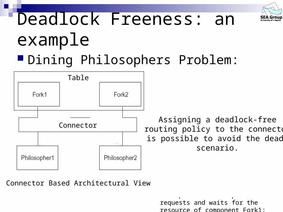
Deadlock Freeness: an example
Dining Philosophers Problem:
Connector Free Architectural View
• component Philosopher1 requests and gets the resource of component Fork1;
• component Philosopher2 requests and gets the resource of component Fork2;
• component Philosopher1 requests and waits for the resource of component Fork2;
• component Philosopher2 requests and waits for the resource of component Fork1;
Deadlock Scenario:
Assigning a deadlock-freerouting policy to the connector
it is possible to avoid the deadlockscenario.
Table
Connector Based Architectural View
Connector
Table

Beyond Deadlock A designer can now think not only of a deadlock-
free routing policy but of a precise scheduling one. For instance he might want: the philosophers to eat in turn or that the Philosopher1 always eats twice before
Philosopher2.
The approaches we are experimenting are based on two existent line of research in the program verification area: usual model checking approach; supervisory control theory.

Beyond Deadlock: Model Checking Approach
We must adapt the usual model checking approach to our approach;
We need: some kind of temporal logic to define properties that represent
unexpected behavior of the system;
an existent translation algorithm of a behavioral property to a graph with the same structure of the connector graph (Büchi Automata Theory);
an existent structural mismatches search strategy to find structural mismatches between portions of the connector graph and a property graph

Property enforcing (third step) By exploiting the automata-based model checking
approach.
Property specification: LTL as specification language; AP={ t : t is a tuple of states in the AC-Graphs where each state
in t is not reachable only through transitions}; BP is the Büchi Automaton (automaton over infinite words)
corresponding to P.
Connector Model: KSK is the Kripke structure corresponding to K; BKSK
is the Büchi Automaton corresponding to KSK;
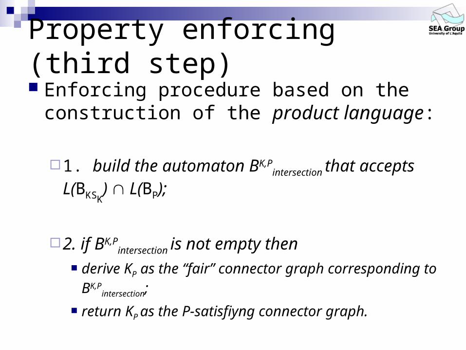
Enforcing procedure based on the construction of the product language:
1. build the automaton BK,Pintersection that accepts
L(BKSK) L(BP);
2. if BK,Pintersection is not empty then
derive KP as the “fair” connector graph corresponding to BK,P
intersection;
return KP as the P-satisfiyng connector graph.
Property enforcing (third step)

Synthesizing dynamic information off black-box components assume a (partial) standard specification for the components
interaction behavior (e.g.: MSC and HMSC): we can adapt a translation algorithm from an HMSC to a finite state machine
to our approach;
Use black-box component inspection techniques (e.g: Interface Propagation Analysis – J. Voas)
inspection techniques are not completely automatic; An inspection technique should benefit of the knowledge of the type of
components and architectural interaction model. we can try to
increase the automation of these techniques and extend them in order to derive a behavioral specification that reflects the
constraints of the architectural model;
We can only synthesize observable behaviors

Our approach: an examplefrom the bMSCs and HMSCs specification to theAC-Graphs for each component (from Sebastian Uchitel,
Jeff Kramer and Jeff Magee):
a
b
c
a
d
AC3
C1 C2 C3
ab
bMSC1
C1 C2 C3c
a
bMSC2
d
bMSC1bMSC2
a
a
bb
bMSC1 bMSC2
HMSC
c
c
a
a
dd

Our approach: an examplefrom the AC-Graphs to the AS-Graphs for eachcomponent:
a
b
c
a
d
AC3
a
b
c d
AS3
a

Our approach: an examplefrom the AS-Graphs to the EX-Graphs for eachcomponent:
a
b
c d
AS3
a
EX3
a?
a3
b3
b?
c?
c3 a?
a3
d3d?

Our approach: an exampleEX-Graphs unification (coordinator graph) and concurrency conflicts avoidance (deadlock-free coordinator graph):
EX3
a?
a3
b3
b?
c?
c3 a?
a3
d3d?
a1
a?
b?
b1EX1
c2
c? a2
a?
d?d2
EX2
a1
a?
c2
c?
K
a1
a3
c2
c3
b3
b1
a2
a3
d3d2
a1
a3
deadlock
K
a1
a3
c2
c3
b3
b1
a2
a3
d3d2

Our approach: an exampleCoordination policy enforcing (failure-free coordinator graph):
K
a1
a3
c2
c3
b3
b1
a2
a3
d3d2
KSK
{a1}{a3}{c2} {c3}
{b3}{b1,d2}
{a2}
{a3}{d3}
P=F((a1 X(!a1 U a2)) (a2 X(!a2 U a1)))
BKS
a1
a3
c2
c3
b3
b1
a2
a3
d3d2
K
b1 d2k1
k2k3
k6
k4 k5 k9
k10
k11
BPCBA
a1 a2
a2 a1
!a1
!a2
true
p0p1
p2
p3 ∩
PCBA=F((a1 X(!a1 U a2)) (a2 X(!a2 U a1)))

Our approach: an exampleCoordination policy enforcing (failure-free coordinator graph):
BKS
a1
a3
c2
c3
b3
b1
a2
a3
d3d2
K
b1 d2k1
k2k3
k6
k4 k5 k9
k10
k11
BPCBA
a1 a2
a2 a1
!a1
!a2
true
p0p1
p2
p3 ∩(k1,p0)
a1a3b3
b1
a2
c2 c3
a2
c2 c3a3
d3d2
a1
(k2,p1)(k3,p1)
(k6,p1)
(k1,p1)
(k4,p1) (k5,p1)(k9,p3)
(k4,p0) (k5,p0) (k9,p2) (k10,p2)
(k11,p2)
(k1,p2)
(k2,p3)c2
c3(k4,p2)
(k5,p2)
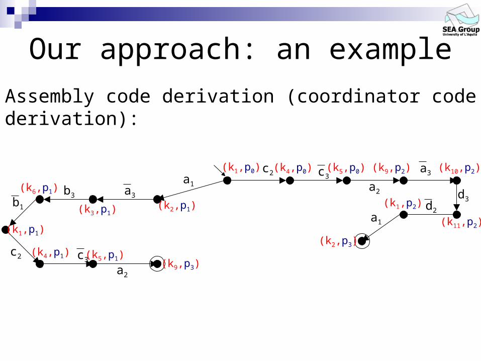
Our approach: an example
Assembly code derivation (coordinator code derivation):
(k1,p0)a1
a3b3b1
c2 c3
c2 c3a3
d3d2
(k2,p1)(k3,p1)
(k6,p1)
(k1,p1)
(k4,p1)
a2
(k5,p1)(k9,p3)
(k4,p0)
a2
(k5,p0) (k9,p2) (k10,p2)
(k11,p2)a1
(k1,p2)
(k2,p3)


A more complex example Starting point:
group-ware systems development by assembling third-party components;
Our proposed approach to this problem: automatic synthesis of failure-free software connectors (i.e.
failure-free coordinators).
An application example of our approach to group-ware systems: a Collaborative Writing (CW) system development by
assembling third-party components.
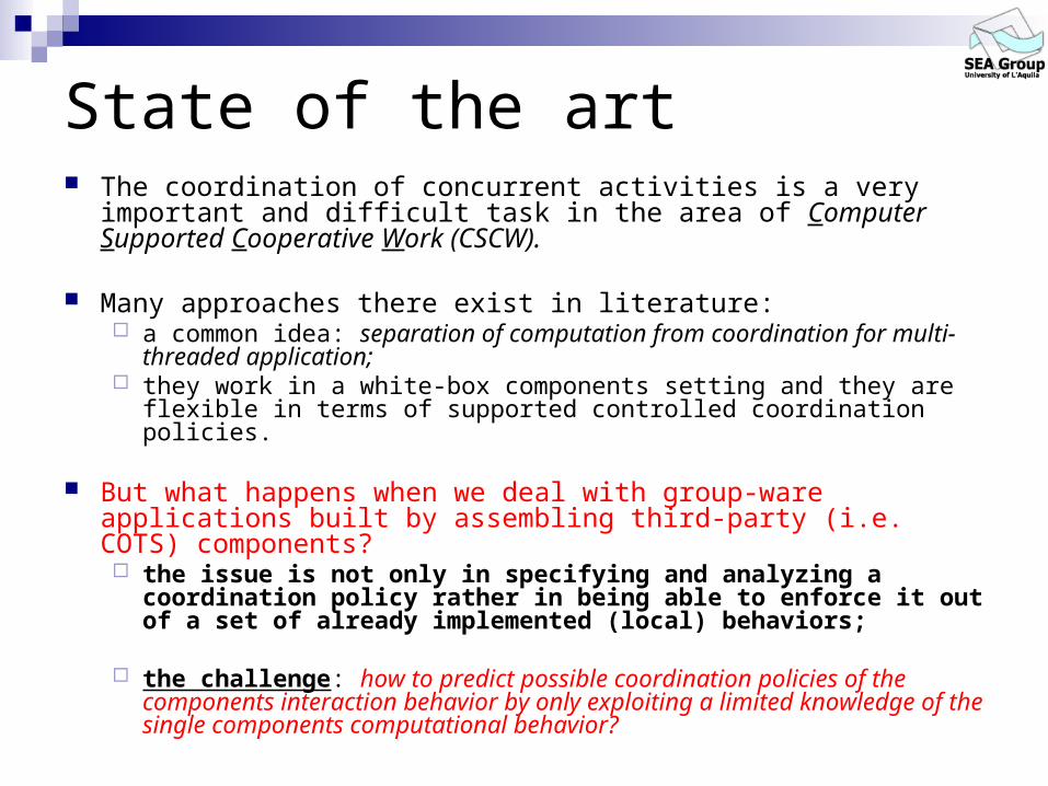
State of the art The coordination of concurrent activities is a very important and
difficult task in the area of Computer Supported Cooperative Work (CSCW).
Many approaches there exist in literature: a common idea: separation of computation from coordination for multi-
threaded application; they work in a white-box components setting and they are flexible in
terms of supported controlled coordination policies.
But what happens when we deal with group-ware applications built by assembling third-party (i.e. COTS) components? the issue is not only in specifying and analyzing a coordination
policy rather in being able to enforce it out of a set of already implemented (local) behaviors;
the challenge: how to predict possible coordination policies of the components interaction behavior by only exploiting a limited knowledge of the single components computational behavior?
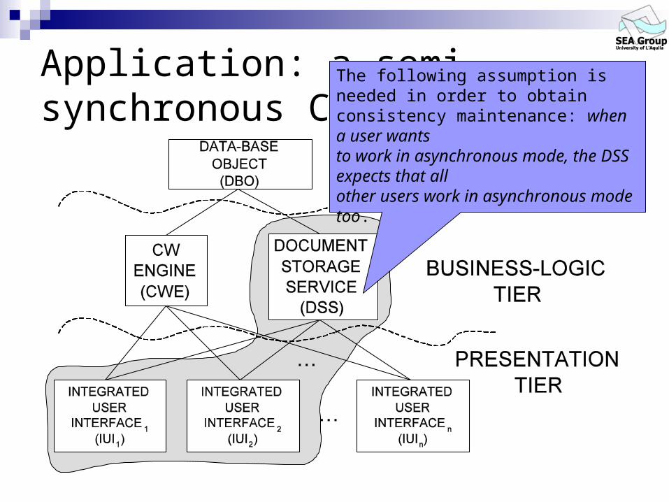
Application: a semi-synchronous CW system
The following assumption is needed in order to obtain consistency maintenance: when a user wantsto work in asynchronous mode, the DSS expects that allother users work in asynchronous mode too.

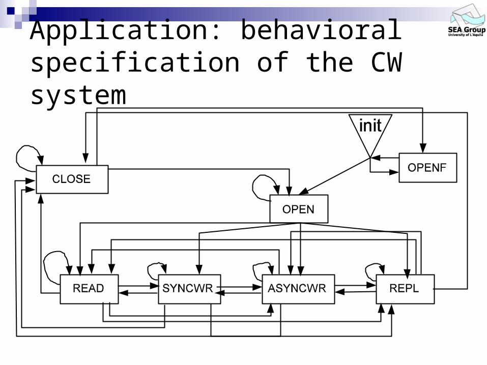
Application: behavioral specification of the CW system
Possible scenarios of the composed system (basic Message Sequence Charts): OPEN: ‘open work session’ scenario; OPENF: ‘failed work session opening’ scenario; CLOSE: ‘close work session’ scenario; READ: ‘document’s content displaying’ scenario; SYNCWR: ‘document’s content synchronous
updating’ scenario; REPL: ‘document’s content replication for asynchronous
updating’ scenario; ASYNCWR: ‘document’s content asynchronous updating’
scenario;

Application: behavioral specification of the CW system
Application: behavioral specification of the CW system

Application: coordination policy specification Coordination policy: “every client who requires to commit an update on the
shared document will eventually always be able to perform this update”.
LTL formula corresponding to the policy: P1 = G(F(write1 )) G(F(write2 ))
Büchi Automaton corresponding to P1:
^
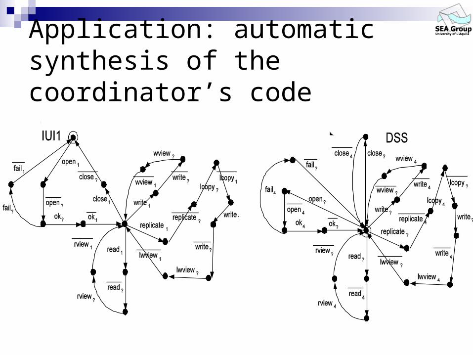
Application: automatic synthesis of the coordinator’s code From the bMSCs and HMSCs specification we
derive the models of the components interaction behavior (AC-Graphs):

Application: automatic synthesis of the coordinator’s code
IUII
DSS

Application: automatic synthesis of the coordinator’s code By assuming the rules of the CBA style, from the
AC-Graphs we derive the models of the connector expected behavior for each component (EX-Graphs):
Application: automatic synthesis of the coordinator’s code

Application: automatic synthesis of the coordinator’s code By unifying each EX-Graph we can derive
the model of the connector behavior in the CBA version of the system:


Application: automatic synthesis of the coordinator’s code In order to obtain the concurrency conflict-free
(i.e. deadlock-free) coordinator we prune all the finite branches of the synthesized connector model.
In order to obtain the model of the coordination policy-satisfying coordinator we enforce the policy on the model of the concurrency conflict-free coordinator: we exploit the automata-based model checking
approach.


Application: automatic synthesis of the coordinator’s code By visiting the graph of the policy-
satisfying coordinator behavior we derive the actual code implementing the coordinator component.
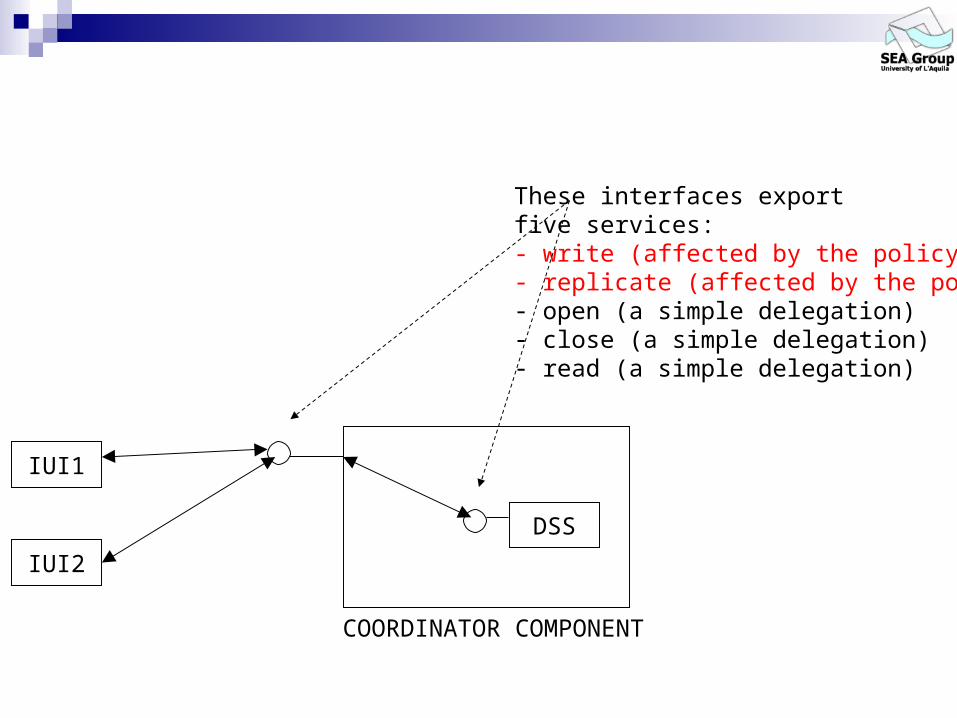
IUI1
IUI2
COORDINATOR COMPONENT
DSS
These interfaces exportfive services:- write (affected by the policy)- replicate (affected by the policy)- open (a simple delegation)- close (a simple delegation)- read (a simple delegation)

HRESULT write(S_DA da) { if(sLbl == 24) { if((chId == 1) && (pState == 0)) { retValue = dssObj->write(da); pState = 1; sLbl = 24; return retValue; } else if((chId == 2) && (pState == 1)) { retValue = dssObj->write(da); pState = 0; sLbl = 24; return retValue; } } else if(sLbl == k56) { if((chId == 1) && (pState == 0)) { retValue = dssObj->write(da); pState = 1; sLbl = 44; return retValue; } else if((chId == 2) && (pState == 1)) { retValue = dssObj->write(da); pState = 0; sLbl = 42; return retValue; } } else if(sLbl == 42) { if((chId == 1) && (pState == 0)) { retValue = dssObj->write(da); pState = 1; sLbl = 24; return retValue; } } else if(sLbl == 44) { if((chId == 2) && (pState == 1)) { retValue = dssObj->write(da); pState = 0; sLbl = 24; return retValue; } }
return E_HANDLE;}
HRESULT write(S_DA da) { if(sLbl == 24) { if((chId == 1) && (pState == 0)) { retValue = dssObj->write(da); pState = 1; sLbl = 24; return retValue; } else if((chId == 2) && (pState == 1)) { retValue = dssObj->write(da); pState = 0; sLbl = 24; return retValue; } }…
write1
write4
wview4
wview1
(k24,p0)
(k24,p1)
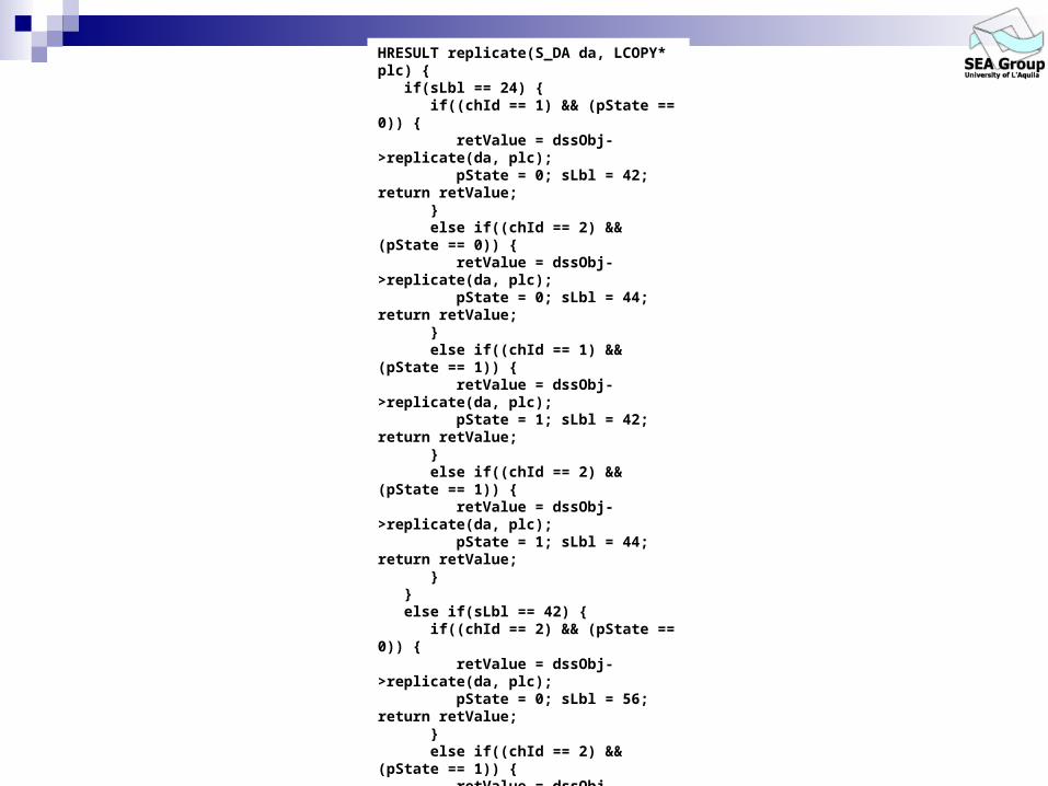
HRESULT replicate(S_DA da, LCOPY* plc) { if(sLbl == 24) { if((chId == 1) && (pState == 0)) { retValue = dssObj->replicate(da, plc); pState = 0; sLbl = 42; return retValue; } else if((chId == 2) && (pState == 0)) { retValue = dssObj->replicate(da, plc); pState = 0; sLbl = 44; return retValue; } else if((chId == 1) && (pState == 1)) { retValue = dssObj->replicate(da, plc); pState = 1; sLbl = 42; return retValue; } else if((chId == 2) && (pState == 1)) { retValue = dssObj->replicate(da, plc); pState = 1; sLbl = 44; return retValue; } } else if(sLbl == 42) { if((chId == 2) && (pState == 0)) { retValue = dssObj->replicate(da, plc); pState = 0; sLbl = 56; return retValue; } else if((chId == 2) && (pState == 1)) { retValue = dssObj->replicate(da, plc); pState = 1; sLbl = 56; return retValue; } } else if(sLbl == k44) { if((chId == 1) && (pState == 0)) { retValue = dssObj->replicate(da, plc); pState = 0; sLbl = 56; return retValue; } else if((chId == 1) && (pState == 1)) { retValue = dssObj->replicate(da, plc); pState = 1; sLbl = 56; return retValue; } }
return E_HANDLE;}
HRESULT replicate(S_DA da, LCOPY* plc) { if(sLbl == 24) { if((chId == 1) && (pState == 0)) { retValue = dssObj->replicate(da, plc); pState = 0; sLbl = 42; return retValue; } else if((chId == 2) && (pState == 0)) { retValue = dssObj->replicate(da, plc); pState = 0; sLbl = 44; return retValue; }…

import idss.idl;...library K1_1_Lib { ... coclass K1_1 { [default] interface IDSS; }}
...class K1_1 : public IDSS { // stores the current state of the connector private static int sLbl;
// stores the current state of the // property automaton private static int pState;
// stores the number of clients private static int clientsCounter = 0;
// channel's number of a client private int chId;
// COM smart pointer; is a reference to // the DSS object private static DSS* dssObj; ...
// the constructor K1_1() { sLbl = 24; pState = 0; clientsCounter++; chId = clientsCounter; dssObj = new DSS(); ... }
// implemented methods ...}

class K1_1 : public IDSS { // stores the current state of the connector private static int sLbl;
// stores the current state of the // property automaton private static int pState;
// stores the number of clients private static int clientsCounter = 0;
// channel's number of a client private int chId;
// COM smart pointer; is a reference to // the DSS object private static DSS* dssObj; ...
// the constructor K1_1() { sLbl = 24; pState = 0; clientsCounter++; chId = clientsCounter; dssObj = new DSS(); ... }
import idss.idl;...library K1_1_Lib { ... coclass K1_1 { [default] interface IDSS; }}
...class K1_1 : public IDSS { // stores the current state of the connector private static int sLbl;
// stores the current state of the // property automaton private static int pState;
// stores the number of clients private static int clientsCounter = 0;
// channel's number of a client private int chId;
// COM smart pointer; is a reference to // the DSS object private static DSS* dssObj; ...
// the constructor K1_1() { sLbl = 24; pState = 0; clientsCounter++; chId = clientsCounter; dssObj = new DSS(); ... }
// implemented methods ...}

What we achieved in this example? We have:
described a connector-based architectural approach to component assembly;
applied it in order to automatically synthesize coordinators components for COTS group-ware applications;
applied it in a real-scale context (namely the Microsoft COM/DCOM applications context).
Our approach focuses on detection of concurrent activities conflicts and on enforcing coordination policies on the assembly.
The software architecture imposed on the composed system allows for easy replacement of a connector with an other one in order to make the whole system flexible with respect to different coordination policies.
The approach is oriented to coordination protocols enforcing besides coordination protocols analysis.

Summarizing
A general framework to synthesize coordinator connectors for black-box component-based systems
Assumes a fixed SA Can capture globally observable
properties

Automatic synthesis tool architectureMSC
specificationof composed
systemscenario1
HMSCspecification of thecomposed system
connector-freearchitecture
From (H)MSC toLTS Translator
AC-Graph 1 AC-Graph 2 AC-Graph 3
AS-Graph 1 AS-Graph 2 AS-Graph 3
EX-Graph 1 EX-Graph 2 EX-Graph 3
UnificationAlgorithm
Connector Model
Failure-free ConnectorModel
Connector CodeBuilder
Failure-freeConnector SourceCode (Assembly
Code)
Property enforcingAlgorithm
MSCspecificationof composed
systemscenario2
MSCspecificationof composed
systemscenario3
AC-Graph 4
AS-Graph 4
EX-Graph 4
intermediatecomponent views
From LTL formulas toBuchi AutomataTranslator
LTL properties set(expectedbehaviors)
Buchi Automata set(unexpected behaviors)
..
..
CB-SimulationChecker
Failure-free ConnectorModel satisfying
componentsassumptions

Dealing with multi-layer systems Idea:
make the layers of a multi-layer architecture completely independent in order to reduce a multi-layer system in a set of single-layer subsystems.
Behavior of a component within the multi-layer hierarchy as: i) top component behavior (Bottom domain AC-Graph); ii) bottom component behavior (Top domain AC-Graph).
C1 C2
C3
C4 C5 C6
2-layer CFA architecture
layer 1
layer 2
C1 C2
Bottom ComponentBehavior of C3
C4 C5 C6
Top ComponentBehavior of C3
single-layer CFA architecture 1
single-layer CFA architecture 2

Compositionality
The approach is compositional with respect to the assembled system evolution;
compositional in the connector synthesis process: K’ = F(KP,C1,..,Cn,Cn+1,..Cn+m);
compositional in the property enforcing process: P is already validated in K’ along the paths
corresponding to the paths of KP.

Example: compositionalityC1:
b a
a
c
d
a3
b1
a1
b3
b1
a1
b2
a2
C2:
b a b a
K
d c
b
CBA1:
add and components
b a b a b aCBA2: a
c
d c
b
d
a5
a1
c5
c4
b5b1
d5
d4
d5
d4d4
d5
a3
b1
a1b3
b1
a1b2
a2
a3
b1a1
b3
b1
a1 b2
a2
KI
S1
SI1
S2
SI2
C3: S3
SI3
C4: S4
SI4
C5: S5
SI5
SII5
SIII5
C1: S1
SI1
C2: S2
SI2
C3: S3
SI3
C4: S4
SI4
C5: S5
SI5
SII5
SIII5
KI1
KI14
{P : P = G(F(<S’1,S’2,S3,X,Y>)) G(F(<S’1,S2,S’3,X,Y>)) for all statesg =<S1,S2,S3,X,Y> in K’ for which the unification procedure has applied the compositional unification step}.
{P1, P2} where P1 = G(F(<S’1,S’2,S3,S4,S5>)) G(F(<S’1,S2,S’3,S4,S5>)) andP2 = G(F(<S’1,S’2,S3,S’4,S’’’5>)) G(F(<S’1,S2,S’3,S’4,S’’’5>)).
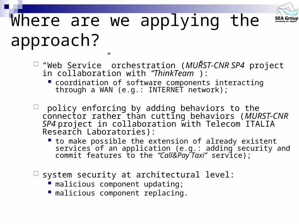
Where are we applying the approach?
“Web Service” orchestration (MURST-CNR SP4 project in collaboration with “ThinkTeam”):
coordination of software components interacting through a WAN (e.g.: INTERNET network);
policy enforcing by adding behaviors to the connector rather than cutting behaviors (MURST-CNR SP4 project in collaboration with Telecom ITALIA Research Laboratories):
to make possible the extension of already existent services of an application (e.g.: adding security and commit features to the “Call&Pay Taxi” service);
system security at architectural level: malicious component updating; malicious component replacing.

What is good
Automatic synthesis of correct assembly
Automatic production of connector code
General coordination properties
Evolutionary, i.e. we can change coordinator
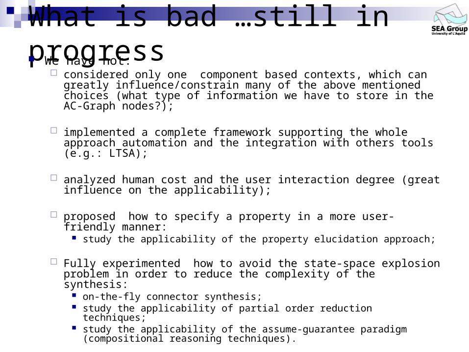
What is bad …still in progress We have not:
considered only one component based contexts, which can greatly influence/constrain many of the above mentioned choices (what type of information we have to store in the AC-Graph nodes?);
implemented a complete framework supporting the whole approach automation and the integration with others tools (e.g.: LTSA);
analyzed human cost and the user interaction degree (great influence on the applicability);
proposed how to specify a property in a more user-friendly manner: study the applicability of the property elucidation approach;
Fully experimented how to avoid the state-space explosion problem in order to reduce the complexity of the synthesis:
on-the-fly connector synthesis; study the applicability of partial order reduction techniques; study the applicability of the assume-guarantee paradigm (compositional
reasoning techniques).

References
Uncovering Architectural Mismatch in Component Behavior D. Compare, Paola Inverardi, , A.L. Wolf Science Of ComputerProgramming (33)2 (1999) pp. 101-131
Static Checking of Systems Behaviors Using Derived Component Assumptions Paola Inverardi, Daniel Yankelevich, Alexander L. Wolf ACM TOSEM vol. 9, n.3, July 2000, pp.239-272.
Proving Deadlock Freedom in Component-Based Programming Paola Inverardi, Sebastian Uchitel Proceedings FASE 2001, LNCS 2029 , Genova April 2001
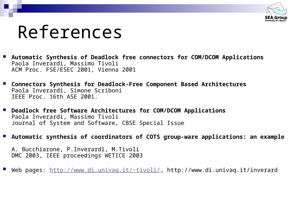
References Automatic Synthesis of Deadlock free connectors for COM/DCOM Applications
Paola Inverardi, Massimo Tivoli ACM Proc. FSE/ESEC 2001, Vienna 2001
Connectors Synthesis for Deadlock-Free Component Based Architectures Paola Inverardi, Simone Scriboni IEEE Proc. 16th ASE 2001.
Deadlock free Software Architectures for COM/DCOM Applications Paola Inverardi, Massimo Tivoli Journal of System and Software, CBSE Special Issue
Automatic synthesis of coordinators of COTS group-ware applications: an example A. Bucchiarone, P.Inverardi, M.Tivoli DMC 2003, IEEE proceedings WETICE 2003
Web pages: http://www.di.univaq.it/~tivoli/, http://www.di.univaq.it/inverard