Embed Size (px)
Citation preview
Software Architecture for Object-Oriented Simulation
Modeling and Simulation Environments: Case Study and Approach
Ranjit Singh [email protected]
Hessam S. Sarjoughian [email protected]
Technical Report
TR-03-09 Sept. 2003
Dept. of Computer Science & Engineering Ira A. Fulton School of Engineering
Arizona State University Tempe, Arizona, 85287-5406, USA
Abstract
During the past two decades, there has been a steady migration towards object-oriented modeling and simulation environments. There exist many issues besides use of a modeling and simulation approach and an object-oriented programming language that are important to account for in developing modeling and simulation environments. For example, it is not only necessary to consider run-time attributes, but also the underlying, non-run-time traits of such environments. In this report, we will (i) examine an object-oriented modeling & simulation environment called DEVSJAVA with respect to its architectural traits and (ii) propose a new software architecture capable of supporting essential functionalities advocated by system-theoretic modeling and simulation concepts and methods. Software architecture concepts and principles are applied to the Discrete Event System Specification modeling and simulation framework and shown to increase DEVSJAVA’s support for a principled approach for conducting simulation studies. This report presents a prototype Tracking Environment which serves both as a vehicle for exemplifying modeling and simulation software architecture concepts and for supporting systematic observation of dynamic simulation models.
2
1. Introduction
For many years, modeling and simulation environments have been used as part of a repertoire of software engineering tools. Engineering of computer-based systems, particularly those that are complex and large-scale, increasingly require simulation modeling. Therefore, it is important that M&S tools support a level of various quality attributes as is typically required of other software applications. Since there are numerous modeling and simulation tools for a variety of modeling methods and simulation techniques, it is useful to study the relationships between the realm of (i) model building & simulation execution in conjunction with (ii) software architecture, design, and development.
Looking at the vast range of domains M&S is applicable to, there are fundamental concepts of Modeling and Simulation independent of any one particular field. A general theory of modeling and simulation, founded on the fundamentals of system theory (e.g., decomposability and aggregation) provides a basis toward creating software-based environments [21,20,13]. With advances in computational sciences and engineering (e.g., design patterns), it is possible to create modeling and simulation environments that can begin to realize additional M&S capabilities (e.g., supporting verification and validation) [17].
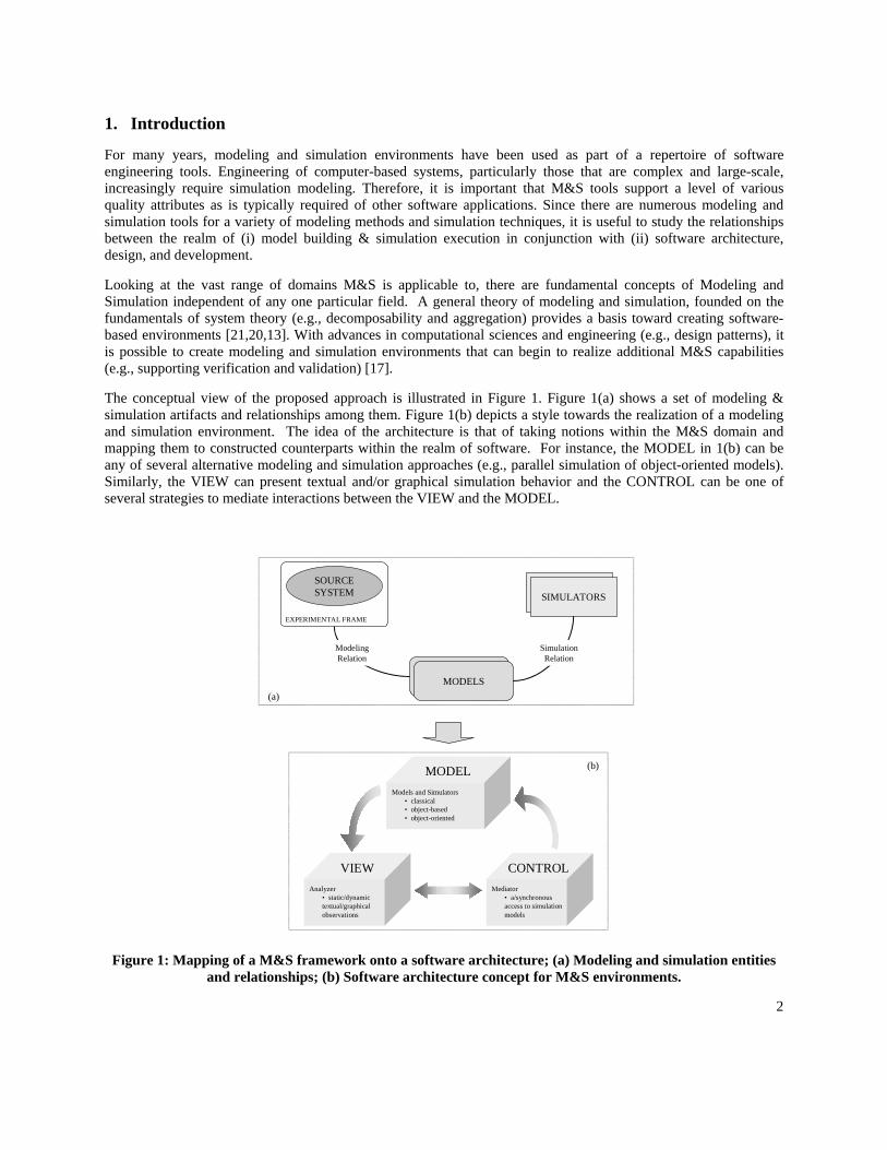
The conceptual view of the proposed approach is illustrated in Figure 1. Figure 1(a) shows a set of modeling & simulation artifacts and relationships among them. Figure 1(b) depicts a style towards the realization of a modeling and simulation environment. The idea of the architecture is that of taking notions within the M&S domain and mapping them to constructed counterparts within the realm of software. For instance, the MODEL in 1(b) can be any of several alternative modeling and simulation approaches (e.g., parallel simulation of object-oriented models). Similarly, the VIEW can present textual and/or graphical simulation behavior and the CONTROL can be one of several strategies to mediate interactions between the VIEW and the MODEL.
MODELS
SIMULATORS
SOURCESYSTEM
EXPERIMENTAL FRAME
SimulationRelation
ModelingRelation
(b)
(a)
Models and Simulators• classical• object-based• object-oriented
MODEL
Analyzer• static/dynamictextual/graphicalobservations
VIEWMediator
• a/synchronous access to simulationmodels
CONTROL
Figure 1: Mapping of a M&S framework onto a software architecture; (a) Modeling and simulation entities and relationships; (b) Software architecture concept for M&S environments.
3
Software architecture plays a key role in developing robust complex simulation environments. For example, the High Level Architecture (HLA) [11,3] software specification offer concepts, methods and processes for developing modeling and simulation environments based on the capabilities provided, for example, by the Run Time Infrastructure (RTI) [11]. Examination of HLA, however, illustrates the importance of supporting a systematic approach for experimentation with simulation models [16]. The remainder of this report presents some important concepts and issues concerning development of software architectures that can support validation of simulation models using the DEVSJAVA simulation environment [1].
1.1 Modeling and Simulation
There exist a variety of frameworks supporting modeling methodologies and simulation techniques [e.g., 8, 9,13,20, 21]. In this report, we briefly describe one such framework that distinguishes three primary artifacts, namely: source system, model, and simulator. To select among many alternative models, the framework employs the basic concept of experiments to reduce the scope of simulation complexity. The following provides a brief description of these entities.
Source System: The real or virtual environment that is intended to be modeled. It is viewed as a source of observable data, in the form of time-indexed trajectories of variables. The data can be gathered from observing real-world systems or virtually constructed.
Model: A model is any physical, mathematical, or logical representation of a system, entity, phenomenon, or process. Models defined in terms of system theory have a sound mathematical foundation with appropriate syntax and semantic underpinnings. A model in system theory can be defined at multiple levels of details or specificity. For example, a model can be specified as input/output trajectories or as a canonical state-space where outputs are defined in terms of inputs and states.
Simulator: A simulator is any computational system (such as a single processor, or a network of processors) that can execute a model to generate its explicit and implicit behavior. A general-purpose simulator can be configured to execute a variety of model types. Such a simulator can be dedicated to a particular model, small class of similar models or capable of accepting multi-formalism models (having components from alternative formalisms such as continuous and discrete event).
Experimental Frame: An experimental frame specifies the conditions under which the system (and/or its model) is experimented with. It specifies, in a computable form, the objectives that motivate a modeling and simulation project. For simulation studies, an experimental frame can be defined as another model that supports experimentation with the model of interest to obtain some data of interest under well-defined, observable conditions. These experiments can be analyzed at run-time or post execution.
1.1.1 Two Fundamental Concepts
Two important relationships known modeling and simulation can be defined among the source system, model, simulator and experiment frame [21]. The modeling relation exists between source system and model for a given experimental frame. The simulation relationship exists between model and its simulator. These relationships can be characterized as appropriate morphisms between their corresponding system specifications thereby useable for model validation and simulation verification.
Modeling Relationship
The modeling relation (or validity relation) refers to the relation between a model, a system and an experimental frame. Validity is often thought of as the degree to which a model faithfully represents its source system. The concept of validity is to answer the question of whether or not it is possible to distinguish the model and source system from one another in a given experimental frame of interest. Hence, it is more practical to require that the model faithfully capture the system behavior only to the extent demanded by the objectives of the simulation study. A basic form of model validation is replicative validity. This form of validation states that for all experiments possible within an experimental frame, all observable behavior of the model and source system are not
4
distinguishable from one another within some acceptable range. An intermediate form of validity is predictive validity. For this to be satisfied, the source system and model should have the same behavior not only for previously observed behavior, but also for unforeseen behavior. For predictive validity, the model is set in a state corresponding to that of the source system. An advanced from of validity is structural validity. It requires agreement at the state-space representation (atomic and composite components). With structural validity the model is not only capable of replicating the data observed from the system but also must mimic in step-by-step, component-by-component fashion, the way that the system undergoes its state transitions.
Simulation Relationship
The simulation relation (or simulator correctness) is a relation between a simulator and a model. A simulator correctly simulates a model if it is guaranteed to faithfully generate the model’s output trajectory given its initial state and its input trajectory. However, it is important for simulators to execute not just one model, but also a family of models. In this case, it is necessary to establish that a simulator will correctly execute a particular class of models (verification). Since the structures of both the simulator and the model are at hand, it may be possible to prove correctness by showing that a homomorphism relation holds. A homomorphism shows a correspondence between simulator and model states that is preserved for transition states and transition and outputs functions given some input regimes.
1.2 Software Design
While there is no exact recipe for developing applications, human experience, practices and research in Software Engineering have lead to the creation of a toolbox of mature methodologies and practices capable of providing guidance [e.g.,5,4,6]. Reference models, architectural styles, design patterns and reference architectures are among the design aids with direct applicability for engineering new systems. Most design endeavors typically begin with the classification of entities and boundaries within the problem domain in efforts to create a reference architecture that formalizes key components and relations. Although no formal reference model is defined here, the previous section presents basic system-theoretic M&S concepts that are useful for the design of a modeling and simulation software tool. It is these concepts that will be applied and mapped to a software architecture in conjunction with known software design strategies and frameworks. Next, some fundamental aspects of the MVC architectural style [7,10,12] and the façade design pattern are described.
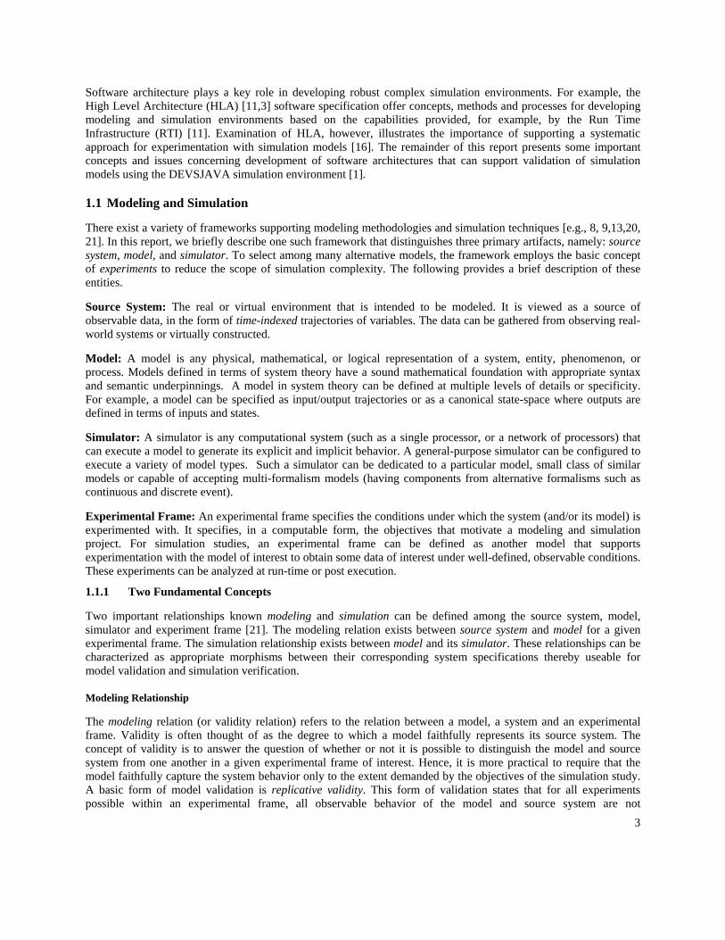
Providing patterns for component types and topology, as well as runtime data/control transfer relations, architectural styles and design patterns lend themselves as initial structural and behavioral blueprints of a software system [4]. Reflecting the earliest of design decisions, the influence of these patterns propagate throughout all developmental phases. Often, as is the case here, software architectures are the result of a heterogeneous mix of patterns and styles, reflecting a synergistic amalgamation that yields a quantitatively larger set of quality attributes than any one single style can offer.
Figure 2: The MVC topology and component responsibilities [12]
5
The Model-View-Controller (MVC) architectural style is a widely used and accepted design blueprint for applications that are interactive in nature. MVC has direct applicability to software with the generic input/processing/output cycle, such as simulator environments. The MVC architectural style is split into three major components. That which encapsulates state and content (while providing access and manipulation to the content) is called the Model. The View is the visual aspect that handles presentation of the Model while the Controller is charged with application level logic and behavioral aspects. Coupling concerns between the MVC components are typically handled through a subscribe/notify protocol between the view and model, and call and return interfaces between the controller and its model/view (Figure 2).
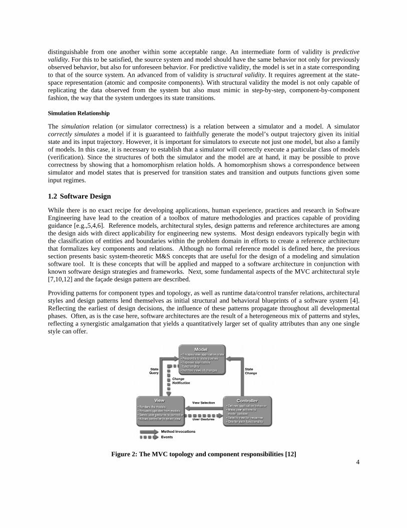
As seen in figure 2, MVC conceptually distinguishes between different functionalities in a system and creates a spatial dissemination between them. Although there are multiple ways to present a similar type of decomposition and topology, MVC is a proven paradigm that is known to intrinsically support a unique variety of quality attributes. In [10] a perspective is given on the MVC architecture in terms of the design patterns that it embodies and uses. Observer, Composite and Strategy are some of the patterns that can be found within MVC. Each of these contributes to the integrability, modifiability, reusability and other quality attributes within the MVC architectural style (Figure 3).
Pattern Integrability Modifiability Reusability Testability
Composite Moderate High Low Moderate Observer High High High Moderate Strategy High High High Moderate
Figure 3: Patterns found in MVC and the levels of quality attributes they contribute
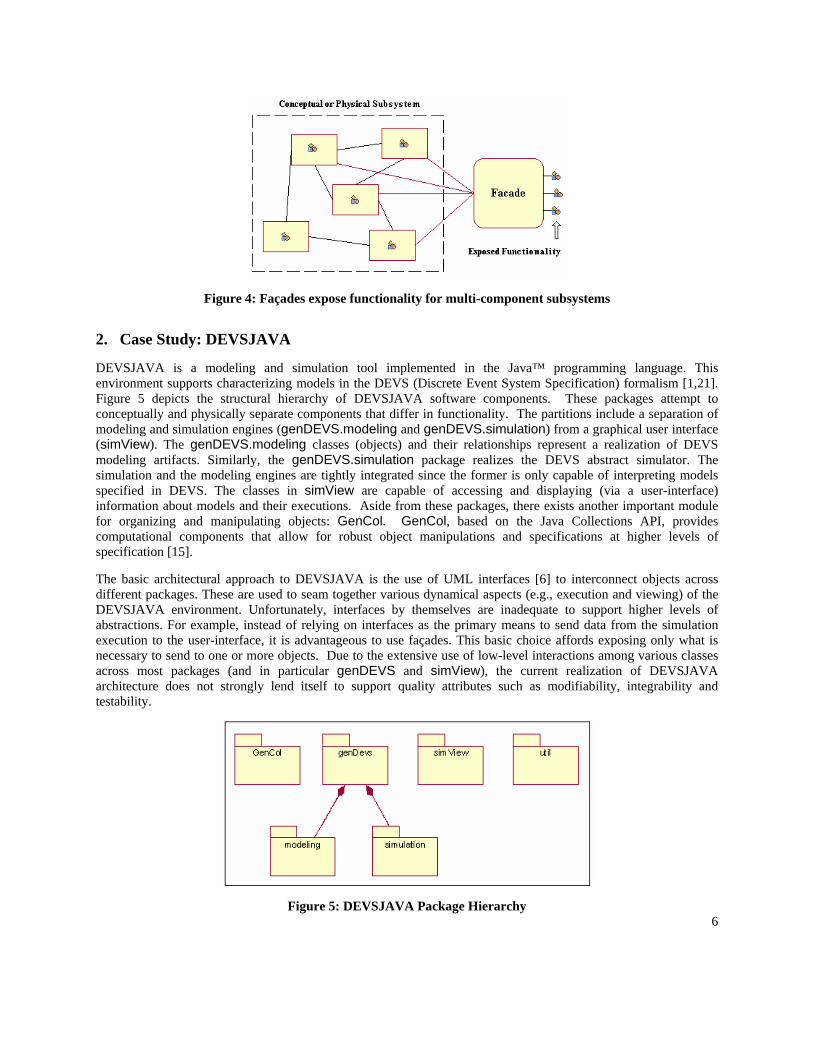
The other strategy used in the proposed software architecture is the façade design pattern. Façades present a unified, high-level interface to collective attributes and behaviors of a subsystem [10]. Façades further the notion of encapsulation, by hiding functionality that is distributed among numerous objects, and providing a single, simple access point for behavior (Figure 4). Façades are more powerful than traditional interfaces in that they also contain logic needed to map defined behavior to appropriate parts of the underlying subsystem.
There are numerous benefits to be found in the structural façade pattern, they include: (i) strengthening encapsulation by exposing only required behavior from subsystems, (ii) providing a layering technique for developing modularized code, (iii) alleviating complex dependencies between components and (iv) promoting weak couplings between components. The first three items above have positive architectural contributions in the areas of modifiability, reusability and testability quality attributes. The last two promote integrability and portability traits.
As mentioned earlier, software architectures come about from a combination of concepts in the problem domain in conjunction with software design constructs (whether they be new frameworks, known strategies or variants on existing patterns). The system theoretic entities in the previous section, and the architectural style and design pattern presented here, will all be used in the approach toward a new software architecture for an object-oriented modeling and simulation environment.
6
Figure 4: Façades expose functionality for multi-component subsystems
2. Case Study: DEVSJAVA
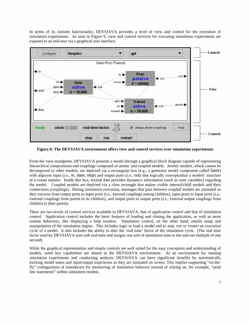
DEVSJAVA is a modeling and simulation tool implemented in the Java™ programming language. This environment supports characterizing models in the DEVS (Discrete Event System Specification) formalism [1,21]. Figure 5 depicts the structural hierarchy of DEVSJAVA software components. These packages attempt to conceptually and physically separate components that differ in functionality. The partitions include a separation of modeling and simulation engines (genDEVS.modeling and genDEVS.simulation) from a graphical user interface (simView). The genDEVS.modeling classes (objects) and their relationships represent a realization of DEVS modeling artifacts. Similarly, the genDEVS.simulation package realizes the DEVS abstract simulator. The simulation and the modeling engines are tightly integrated since the former is only capable of interpreting models specified in DEVS. The classes in simView are capable of accessing and displaying (via a user-interface) information about models and their executions. Aside from these packages, there exists another important module for organizing and manipulating objects: GenCol. GenCol, based on the Java Collections API, provides computational components that allow for robust object manipulations and specifications at higher levels of specification [15].
The basic architectural approach to DEVSJAVA is the use of UML interfaces [6] to interconnect objects across different packages. These are used to seam together various dynamical aspects (e.g., execution and viewing) of the DEVSJAVA environment. Unfortunately, interfaces by themselves are inadequate to support higher levels of abstractions. For example, instead of relying on interfaces as the primary means to send data from the simulation execution to the user-interface, it is advantageous to use façades. This basic choice affords exposing only what is necessary to send to one or more objects. Due to the extensive use of low-level interactions among various classes across most packages (and in particular genDEVS and simView), the current realization of DEVSJAVA architecture does not strongly lend itself to support quality attributes such as modifiability, integrability and testability.
Figure 5: DEVSJAVA Package Hierarchy
7
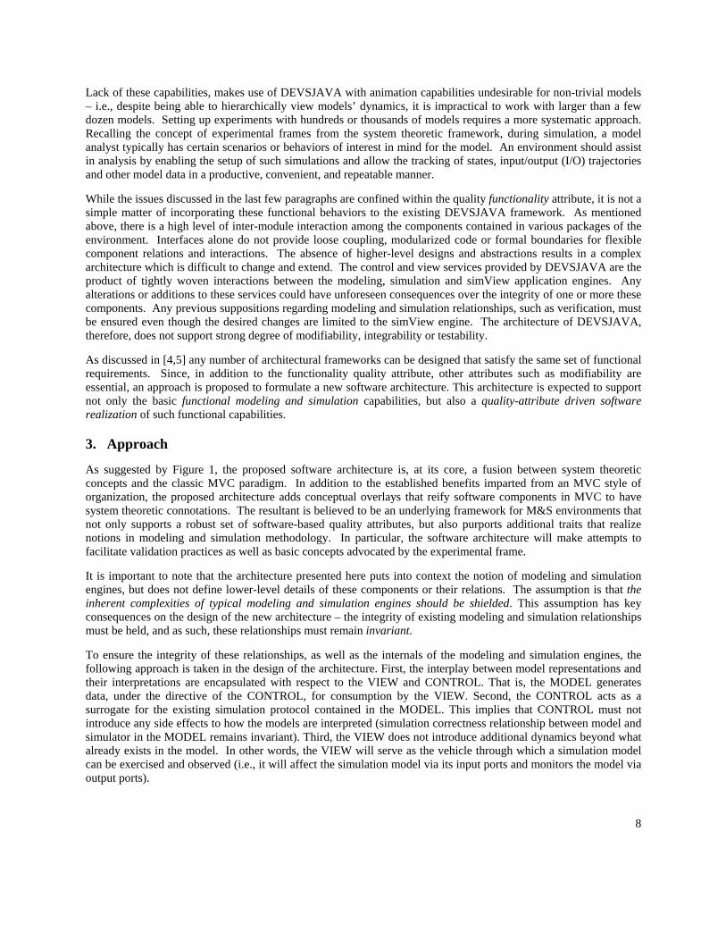
In terms of its runtime functionality, DEVSJAVA provides a level of view and control for the execution of simulation experiments. As seen in Figure 6, view and control services for executing simulation experiments are exposed to an end-user via a graphical user interface.
Control
Control
View
Figure 6: The DEVSJAVA environment offers view and control services over simulation experiments
From the view standpoint, DEVSJAVA presents a model through a graphical block diagram capable of representing hierarchical compositions and couplings composed of atomic and coupled models. Atomic models, which cannot be decomposed to other models, are depicted via a rectangular box (e.g., a generator model component called Genr) with adjacent input (i.e., in, start, stop) and output ports (i.e., out) that logically conceptualize a models’ structure in a visual manner. Inside this box, textual data provides dynamics information (such as state variables) regarding the model. Coupled models are depicted via a clear rectangle that makes visible internal/child models and their connections (couplings). During simulation execution, messages that pass between coupled models are animated as they traverse from output ports to input ports (i.e., internal couplings among children), input ports to input ports (i.e., external couplings from parent to its children), and output ports to output ports (i.e., external output couplings from children to their parent).
There are two-levels of control services available in DEVSJAVA, that of application control and that of simulation control. Application control includes the basic features of loading and closing the application, as well as more routine behaviors, like displaying a help window. Simulation control, on the other hand, entails setup and manipulation of the simulation engine. This includes logic to load a model and to step, run or restart an execution cycle of a model. It also includes the ability to alter the ‘real time’ factor of the simulation cycle. (The real time factor used by DEVSJAVA uses soft real-time and assigns one unit of simulation time to the user-set multiple of one second)
While the graphical representation and simple controls are well suited for the easy conception and understanding of models, some key capabilities are absent in the DEVSJAVA environment. As an environment for running simulation experiments and conducting analysis, DEVSJAVA can have significant benefits by automatically tracking model states and input/output trajectories as they are animated on screen. This implies supporting “on-the-fly” configuration of transducers for monitoring of simulation behavior instead of relying on, for example, “print line statements” within simulation models.
8
Lack of these capabilities, makes use of DEVSJAVA with animation capabilities undesirable for non-trivial models – i.e., despite being able to hierarchically view models’ dynamics, it is impractical to work with larger than a few dozen models. Setting up experiments with hundreds or thousands of models requires a more systematic approach. Recalling the concept of experimental frames from the system theoretic framework, during simulation, a model analyst typically has certain scenarios or behaviors of interest in mind for the model. An environment should assist in analysis by enabling the setup of such simulations and allow the tracking of states, input/output (I/O) trajectories and other model data in a productive, convenient, and repeatable manner.
While the issues discussed in the last few paragraphs are confined within the quality functionality attribute, it is not a simple matter of incorporating these functional behaviors to the existing DEVSJAVA framework. As mentioned above, there is a high level of inter-module interaction among the components contained in various packages of the environment. Interfaces alone do not provide loose coupling, modularized code or formal boundaries for flexible component relations and interactions. The absence of higher-level designs and abstractions results in a complex architecture which is difficult to change and extend. The control and view services provided by DEVSJAVA are the product of tightly woven interactions between the modeling, simulation and simView application engines. Any alterations or additions to these services could have unforeseen consequences over the integrity of one or more these components. Any previous suppositions regarding modeling and simulation relationships, such as verification, must be ensured even though the desired changes are limited to the simView engine. The architecture of DEVSJAVA, therefore, does not support strong degree of modifiability, integrability or testability.
As discussed in [4,5] any number of architectural frameworks can be designed that satisfy the same set of functional requirements. Since, in addition to the functionality quality attribute, other attributes such as modifiability are essential, an approach is proposed to formulate a new software architecture. This architecture is expected to support not only the basic functional modeling and simulation capabilities, but also a quality-attribute driven software realization of such functional capabilities.
3. Approach
As suggested by Figure 1, the proposed software architecture is, at its core, a fusion between system theoretic concepts and the classic MVC paradigm. In addition to the established benefits imparted from an MVC style of organization, the proposed architecture adds conceptual overlays that reify software components in MVC to have system theoretic connotations. The resultant is believed to be an underlying framework for M&S environments that not only supports a robust set of software-based quality attributes, but also purports additional traits that realize notions in modeling and simulation methodology. In particular, the software architecture will make attempts to facilitate validation practices as well as basic concepts advocated by the experimental frame.
It is important to note that the architecture presented here puts into context the notion of modeling and simulation engines, but does not define lower-level details of these components or their relations. The assumption is that the inherent complexities of typical modeling and simulation engines should be shielded. This assumption has key consequences on the design of the new architecture – the integrity of existing modeling and simulation relationships must be held, and as such, these relationships must remain invariant.
To ensure the integrity of these relationships, as well as the internals of the modeling and simulation engines, the following approach is taken in the design of the architecture. First, the interplay between model representations and their interpretations are encapsulated with respect to the VIEW and CONTROL. That is, the MODEL generates data, under the directive of the CONTROL, for consumption by the VIEW. Second, the CONTROL acts as a surrogate for the existing simulation protocol contained in the MODEL. This implies that CONTROL must not introduce any side effects to how the models are interpreted (simulation correctness relationship between model and simulator in the MODEL remains invariant). Third, the VIEW does not introduce additional dynamics beyond what already exists in the model. In other words, the VIEW will serve as the vehicle through which a simulation model can be exercised and observed (i.e., it will affect the simulation model via its input ports and monitors the model via output ports).
9
With these invariants, modeling and simulation engines, such as those in DEVSJAVA, can be included into the proposed apporach without a loss of integrity. The benefit is a new software architecture capable of providing a rich and expandable underpinning for developing simulation environments.
3.1 Software Architecture
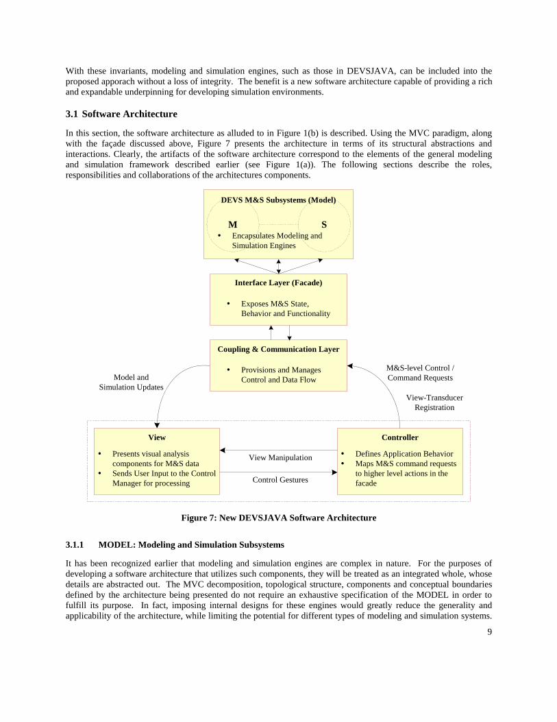
In this section, the software architecture as alluded to in Figure 1(b) is described. Using the MVC paradigm, along with the façade discussed above, Figure 7 presents the architecture in terms of its structural abstractions and interactions. Clearly, the artifacts of the software architecture correspond to the elements of the general modeling and simulation framework described earlier (see Figure 1(a)). The following sections describe the roles, responsibilities and collaborations of the architectures components.
Interface Layer (Facade)
Exposes M&S State,Behavior and Functionality
Controller
Defines Application BehaviorMaps M&S command requeststo higher level actions in thefacade
View
Presents visual analysiscomponents for M&S dataSends User Input to the ControlManager for processing
M SEncapsulates Modeling andSimulation Engines
DEVS M&S Subsystems (Model)
View Manipulation
Control Gestures
M&S-level Control /Command RequestsModel and
Simulation Updates
Coupling & Communication Layer
Provisions and ManagesControl and Data Flow
View-TransducerRegistration
Figure 7: New DEVSJAVA Software Architecture
3.1.1 MODEL: Modeling and Simulation Subsystems
It has been recognized earlier that modeling and simulation engines are complex in nature. For the purposes of developing a software architecture that utilizes such components, they will be treated as an integrated whole, whose details are abstracted out. The MVC decomposition, topological structure, components and conceptual boundaries defined by the architecture being presented do not require an exhaustive specification of the MODEL in order to fulfill its purpose. In fact, imposing internal designs for these engines would greatly reduce the generality and applicability of the architecture, while limiting the potential for different types of modeling and simulation systems.
10
Instead the MODEL will only be defined by its role, responsibilities and boundaries with respect to the architecture while the integrity of its internals (i.e. modeling & simulation relationships) will not be compromised by its integration within this framework.
As the composite of two important subsystems, the MODEL is responsible for encapsulating core M&S logic. The modeling and simulation engines within the MODEL define entities, behaviors and relations needed to realize software counterparts of modeling formalisms and associated simulation protocols. (Note that these engines depend on supporting containers classes) Serving as the source of dynamic behavior of the architecture, the MODEL contains all the classes, interfaces, components and subcomponents necessary to form a computational infrastructure for modeling and simulation activities.
Although the internals of the MODEL is not considered in the architecture, the external subset of static and dynamic properties exposed by the MODEL is key for interaction purposes with the CONTROL and VIEW. From a software perspective, there are important interface and impendence matching issues that must be addressed in order to facilitate connections and communication among the MVC parts. From a conceptual perspective, there are important levels of abstractions to be created which discerns the modeling and simulation artifacts that are exchanged and understood within the MVC. With these points of interest in mind, two primary levels of concern can be established, that of interface, and that of coupling and communication.
The interface level deals directly with structural and behavioral aspects that are exposed from the MODEL and are available to the VIEW and CONTROLLER. In terms of software entities, this translates to a specific structured set of classes that has both design-level values as well as domain-level correlations to modeling and simulation concepts. For instance, a model is a class with a name attribute of type String and a simulator is a class capable of running a model with {start} and {stop} functionality (methods). Within the presented architecture, the interface level is realized through a façade called the interface layer. A set of surrogate classes is created that represent abstracted M&S concepts whose actual detailed computational logic is hidden inside the MODEL.
The coupling and communication level complements the interface level. Once an interface is established for a MODEL, it must somehow be connected or coupled to the VIEW and CONTROLLER. Additionally, there are communication issues, such as timing, synchronization, concurrency, data format and more that must be handled with respect to the context of the M&S data and control flows being transferred. The architecture includes a coupling and communication layer that sits between the interface façade and the view and controller to tackle these issues. Both the interface layer and the coupling & communication layer are discussed below in further detail.
3.1.2 FAÇADE: Interface Layer
The role of the interface layer is that of a well-defined bridge capable of providing access and interaction with a MODEL. The interface layer is implemented through a façade and exposes those mechanisms in the MODEL needed to support data and control services required by the VIEW and CONTROLLER. It is the presence of this façade allows the MODEL to maintain its ‘black box’ nature. Through the interface layer, the complexities of the MODEL are managed. As illustrated in Figure 7, only the interface layer façade is capable of interacting with the MODEL and reaching its inner components. With the proper implementation of the interface layer, the integrity of the MODEL (i.e. modeling and simulation relationships) can be maintained. This logically supports the addition of components outside of the MODEL such that they are known not to interfere with the correct operation of entities within the MODEL.
Fundamentally, the interface layer does not add any new functionality to the MODEL, but rather presents two conceptual sets of surrogate-views for MODEL. The abstract modeling set defines the structure of simulation models and provides a means for accessing their attributes. The abstract simulator set defines simulation functionality and behavior. Together these two entities offer concrete syntactic and semantic software structures while imparting a homomorphic view on the MODEL.
The following is an abbreviated list of requirements that need to be provided by the abstract modeling and simulation sets within the interface layer. Since it is difficult to generate such a list for all possible MODEL types,
11
the subsequent requirements are tailored towards the DEVS modeling and simulation engines and the proposed Tracking environment.
Abstract Modeling Set:
An explicit, well defined class structure for models. Access to static model information (e.g., ports, input/output values, etc.). Access to dynamic model information (e.g., state information, etc.). Well-defined set of data-types used by the simulation models (e.g., integer, strings, etc.). Additional support mechanisms required within the MVC (e.g., meta-model information for the VIEW).
Abstract Simulation Set:
An explicit, well defined set of simulation behaviors (e.g., run, step, pause, restart, etc.). Access to general simulation information (e.g., elapsed times, output values, etc.). Loading of MODEL level models with the automatic creation of façade level modeling counterparts. Listing and access to all loaded models. Additional support mechanisms required within the MVC (e.g., distributed simulation execution).
In comparison to the traditional MVC, the interface layer façade adds an additional level of flexibility to the design. MVC extended with a façade facilitates higher degree of interactions and thus enhances the encapsulation of the MODEL [10]. This allows the MODEL to have a greater range of design choices than normally afforded by the classic MVC design paradigm. For instance, a simulator could be implemented for a single-processor or multi-processor system, or it could run models sequentially or in parallel. Regardless of these choices, from a software standpoint, only the façade is affected.
3.1.3 Coupling and Communication Layer
As inferred from the name, the Coupling and Communication (C&C) layer is responsible for establishing the mechanisms and protocols needed to connect the MODEL (through the façade) to VIEW and CONTROLLER. This entails more than making an undesirable ‘hard-wiring’ between these components. Between the realm of software design and the problem domain of simulation environments, there is a plethora of hybrid concerns to address. Timing, synchronization, concurrency, data format and distributed connections are some of the most important issues that can arise in communicating data and control between the MODEL and its VIEW/CONTROLLER. The existence and placement of the coupling and communication layer within the software architecture, makes it an attractive candidate for supporting and facilitating such issues.
Traditionally, models in MVC are classified as either being passive or active. Models that are said to be passive do not make any provisions for their participation in the MVC [7]. Consider, for instance, a plain text editor that utilizes the MVC paradigm and whose model is a simple String data type [7]. The communication within the MVC for the text editor consists solely of the controller (i) accepting input (keystrokes) from the user, (ii) sending an update to the model, and then (iii) requesting the view to refresh itself. In this type of scenario, the control space of all application components is contained within the control space of the Controller MVC component. The couplings are three straightforward unidirectional links between the controller and the model, the controller and the view, and the view and the model.
Most models, however (like the one in the presented architecture), are not passive and rather fall into the active category. In an MVC containing an active model, there is more than one control space and the CONTROLLER is not always aware of changes that occur in the model. Hence communication is more sophisticated then the tri-event sequence of a passive model, and by extension so is the couplings. Conventional solutions to this problem place additional logic (typically an Observer [10] type of pattern) within the model to facilitate update notification. The view registers itself as an observer to the model, and the model publishes changes as they occur.
Although the MODEL will need to provide some amenities for model updates (via the interface layer), the coupling and communication layer can subsume much of the logic needed for data flow services. The result of this decoupling is a more adaptable architecture whose communication protocols and logic to the VIEW/CONTROLLER can be
12
enhanced or modified without alteration or influence to the MODEL. In addition, since the VIEW and CONTROLLER will connect only to the C&C layer, control flow will be specified within it. This has the effect of the C&C component acting as a sort of additional façade layer capable of further refining or specializing the exposed services of the MODEL.
3.1.4 VIEW: Observing Behavior
In a traditional MVC design, the view’s objective is generically defined as ‘rendering the model’ in some fashion that applies to the context of the application. In this architecture, the VIEW is further specialized by assigning context in terms of two key responsibilities, that of (i) providing a gateway between the end-user and application functionality, and that of (ii) facilitating experimentation with simulation models.
The notions for (i) are fairly straightforward; the VIEW provides an access point for a user to interact with the system, particularly through a Graphical User Interface (GUI). The VIEW supplies a visual representation of simulation models and offers a means to inspect details or interact with those models. In classic MVC designs, the VIEW is MODEL-aware in the sense that it has explicit knowledge regarding the structure and semantics of artifacts exposed by the MODEL. Here the VIEW is MODEL-aware with respect to the Interface Layer façade. The visual representation of models and their level of interaction are based on the structural and behavioral abstractions defined at the interface layer façade.
The idea of (ii) is that of considering the VIEW as a workspace for creating, conducting and analyzing dynamic simulation scenarios. The extent to which the view can facilitate validation of models, however, is dependent upon the functionality exposed via the façade. For instance, at minimum there should be a means to initialize a system and monitor simulation model data at the I/O level. This, in turn, will allow mechanisms in the view such as on-the-fly view transducers that offer graphical perspectives on I/O data. More sophisticated features could also be supported, such as being able to alter modeling dynamics for simulations, (e.g. structural representation [18,14]), but require significantly more effort in terms of design and implementation.
In its effort to support both (i) and (ii), the VIEW must handle some interesting issues, including the preservation of logical correctness as well as more HCI types of concerns such as scalability and usability. The first topic deals with the accurate representation of data and semantics pushed down from the MODEL. Generally, MVC designs are susceptible to the liar-view bug [2] in which the challenges of synchronizing the current state of the MODEL with its visual depiction in the VIEW can lead to erroneous results. In modeling and simulation this type of flaw can have detrimental effects on the outcome of results and will nullify attempts at validation. It is imperative for the data depicted by the VIEW to at least maintain logical correctness. This implies that the timing and data values for all simulation data are accurate and both syntactically and semantically match that which is in the MODEL. It is not, however, mandatory for the VIEW to maintain visual correctness at varying levels of resolutions. Unless explicitly accounted for within the MODEL and its collaboration protocols, there will always be some delay between the MODEL’s state and its visual representation within the VIEW. In addition, it is possible for some kinds of a simulation model behavior not to be visible – for example due to concurrency or need for fast simulation. For modeling and simulation applications, in general, these kinds of discrepancies are acceptable. To maintain logical correctness then, these concerns must be addressed both internally to the VIEW, CONTROLLER and C&C layer and well as externally between their couplings.
The other concerns addressed by the VIEW are HCI issues such as scalability and usability. As noted in the above case study, the current version of DEVSJAVA uses graphical blocks as a visual depiction for simulation models and their hierarchies. While this type of representation is viable for a small number of simulation models, it does not scale well as the number of models increase. This leaves practical application of the environment less to real world problems and more to pedagogic purpose. The usefulness and feasibility of an environment to setup a simulation scenario and monitor results is dependent upon the attributes of scalability and usability. The appearance, setup, layout, and behavior of the VIEW and its subcomponents are accountable for a substantial part of these concerns and should be addressed accordingly.
13
3.1.5 CONTROLLER: Communicating Behavior
Within the architecture, there are two different echelons of ‘control’ present: one is at the application level and the other at the MODEL level. Application-level logic resides with the VIEW and CONTROLLER and entails behavior local to these components. For instance, initialization and termination of the environment, window manipulation, and data interpretation all are encapsulated under application level logic. MODEL-level logic is encapsulated within the MODEL, and is exposed vertically through the façade and C&C layers. MODEL-level logic includes behaviors such as simulation and model manipulation (Run, Pause, Inject Input, etc). As the view exposes both echelons of control, the CONTROLLER defines application-level logic and acts as surrogate for MODEL-level logic.
Runtime logic within the Controller focus’ primarily on one task, that of processing and providing logic for ‘control gestures’ that are sent from the View during runtime. Control gestures are high-level semantic events that encapsulate a control request (for example starting a simulation, or exiting the system). Control gestures are typically triggered in the View by a user request or action. The different types of control gestures available are enumerated within the Controllers’ subsystem. If the logic for processing a control request is not defined within the controller (MODEL-level logic) then the controller simply maps the request to an appropriate corresponding call to the Coupling and Communication layer. Control gestures provide a well-structured connection between the View and Controller and present behavioral capabilities in a more formal manner than direct method calls. Other traits of the Controller are those characteristic of most controllers in MVC. Changes in the controller are generally driven by alterations to application-level system behavior or cascade changes from the C&C or View.
3.2 Validation Through VIEW and CONTROLLER
An important rationale for the development of a new framework for M&S environments was to support a rigorous systematic basis for model configuration and observation of simulation models. The development of such a software architecture that includes system-theoretic concepts can lead to incentives such as validation facilities. To our knowledge there is no generic, domain independent software framework capable of accepting a model (of a certain formalism) and based on system theoretic semantics (as opposed to its domain semantics) set up and create dynamic simulation experiments that support validation. The presented architecture aims at accomplishing this by providing a system-theoretic experimental frame that is decoupled from the model and is capable of setting up scenarios that lend themselves toward validation.
The VIEW and CONTROLLER play a particularly important role as they define a workspace capable of initializing, and observing experimental scenarios independent of the model under examination. Modelers are empowered to construct scenarios that will yield results for validating multiple aspects of simulation models. Replicative, predictive and even structural (depending upon how much is exposed by the MODEL, Interface and C&C Layers) validity can be performed. This is accomplished mainly through a library of analysis components within the VIEW that are dynamically customizable to track explicit sets of model simulation data during a simulation run. These components are capable of giving visual (graphs, charts, etc) and logical (text, tables, etc) forms of analysis for validation.
4. Tracking Environment Implementation
To provide more depth to the concepts above and to illustrate feasibility, a simplistic tracking environment was developed using the presented architecture as a basis. This illustrative application allows setup and execution of simulation experiments from which simulation model data sets (state variables, input/output ports etc) can be dynamically selected and observed for any number of models during run-time. Model analysis and validation checking facilities includes tabular data output that can be exported to other tools such as Excel for further manipulation.
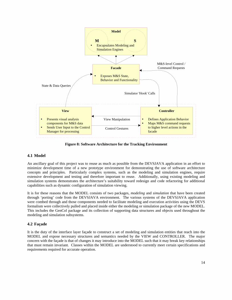
Figure 8 presents the core components and connections that underlie the detailed design and implementation of the tracking environment. An important observation to note is the absence of the coupling and communication layer. For this environment, the C&C layer is unnecessary as its functionality is included in the view and the controller.
14
Facade
Exposes M&S State,Behavior and Functionality
Controller
Defines Application BehaviorMaps M&S command requeststo higher level actions in thefacade
View
Presents visual analysiscomponents for M&S dataSends User Input to the ControlManager for processing
M SEncapsulates Modeling andSimulation Engines
Model
View Manipulation
Control Gestures
M&S-level Control /Command Requests
Simulator 'Hook' Calls
State & Data Queries
Figure 8: Software Architecture for the Tracking Environment
4.1 Model
An ancillary goal of this project was to reuse as much as possible from the DEVSJAVA application in an effort to minimize development time of a new prototype environment for demonstrating the use of software architecture concepts and principles. Particularly complex systems, such as the modeling and simulation engines, require extensive development and testing and therefore important to reuse. Additionally, using existing modeling and simulation systems demonstrates the architecture’s suitability toward redesign and code refactoring for additional capabilities such as dynamic configuration of simulation viewing.
It is for these reasons that the MODEL consists of two packages, modeling and simulation that have been created through ‘porting’ code from the DEVSJAVA environment. The various systems of the DEVSJAVA application were combed through and those components needed to facilitate modeling and execution activities using the DEVS formalism were collectively pulled and placed inside either the modeling or simulation package of the new MODEL. This includes the GenCol package and its collection of supporting data structures and objects used throughout the modeling and simulation subsystems.
4.2 Façade
It is the duty of the interface layer façade to construct a set of modeling and simulation entities that reach into the MODEL and expose necessary structures and semantics needed by the VIEW and CONTROLLER. The major concern with the façade is that of changes it may introduce into the MODEL such that it may break key relationships that must remain invariant. Classes within the MODEL are understood to currently meet certain specifications and requirements required for accurate operation.
15
The constraints on the façade are that it must not:
Modify the MODEL in a way that alters the existing modeling or simulation relation. Expose behavioral attributes that allow the alteration of the existing modeling or simulation relation.
These constraints are imposed by the software architecture, but it is up to the developer to ensure they are maintained.
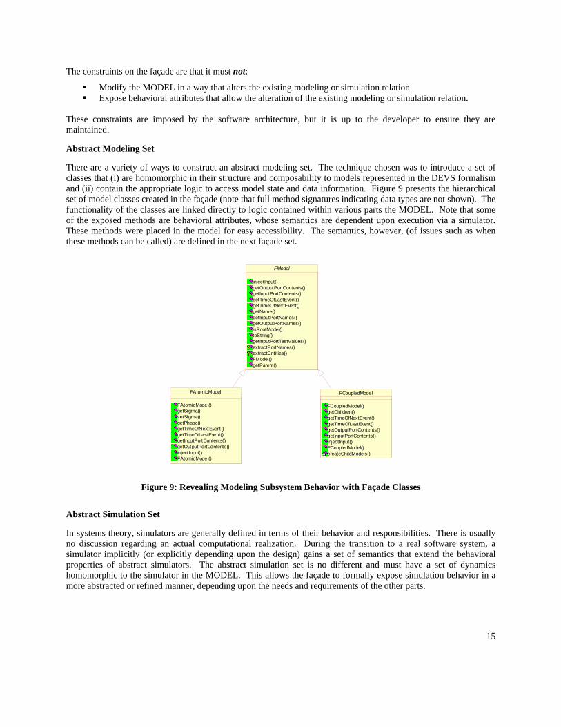
Abstract Modeling Set
There are a variety of ways to construct an abstract modeling set. The technique chosen was to introduce a set of classes that (i) are homomorphic in their structure and composability to models represented in the DEVS formalism and (ii) contain the appropriate logic to access model state and data information. Figure 9 presents the hierarchical set of model classes created in the façade (note that full method signatures indicating data types are not shown). The functionality of the classes are linked directly to logic contained within various parts the MODEL. Note that some of the exposed methods are behavioral attributes, whose semantics are dependent upon execution via a simulator. These methods were placed in the model for easy accessibility. The semantics, however, (of issues such as when these methods can be called) are defined in the next façade set.
FAtomicModel
FAtomicModel()getSigma()setSigma()getPhase()getTimeOfNextEvent()getTimeOfLastEvent()getInputPortContents()getOutputPortContents()inject Input()FAtomicModel()
FCoupledModel
FCoupledModel()getChildren()getTimeOfNextEvent()getTimeOfLastEvent()getOutputPortContents()getInputPortContents()injectInput()FCoupledModel()createChildModels()
FModel
injectInput()getOutputPortContents()getInputPortContents()getTimeOfLastEvent()getTimeOfNextEvent()getName()getInputPortNames()getOutputPortNames()isRootModel()toString()getInputPortTestValues()extractPortNames()extractEntities()FModel()getParent()
Figure 9: Revealing Modeling Subsystem Behavior with Façade Classes
Abstract Simulation Set
In systems theory, simulators are generally defined in terms of their behavior and responsibilities. There is usually no discussion regarding an actual computational realization. During the transition to a real software system, a simulator implicitly (or explicitly depending upon the design) gains a set of semantics that extend the behavioral properties of abstract simulators. The abstract simulation set is no different and must have a set of dynamics homomorphic to the simulator in the MODEL. This allows the façade to formally expose simulation behavior in a more abstracted or refined manner, depending upon the needs and requirements of the other parts.
16
Initial
Simulation Active
Simulating
Pause
Simulating
PauseFinal
simulate
reset
Allowed behavior in state {Initial}:
Root Coupled Model Inject()Atomic Model Inject()Run()Step(n) where n > 0
Allowed behavior in state {Simulating}:
RequestPause()
Allowed behavior in state{Pause}:
Atomic Model Inject()Run()Step(n) where n > 0Reset()
Allowed behavior in state {Final}
Reset()
Allowed behavior in all states:
Read and access Modeling and Simulation information.*Note: In state {Simulating}, M&S information is only guarenteed correct during a hook execution.*
reset
reset
suspend simulate
end
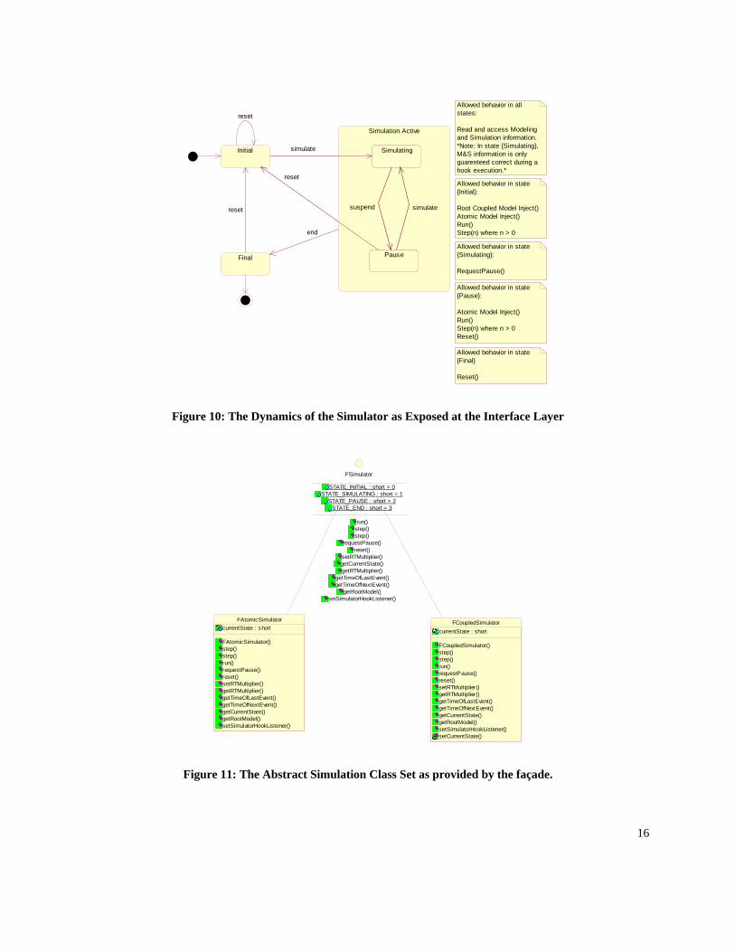
Figure 10: The Dynamics of the Simulator as Exposed at the Interface Layer
FCoupledSimulatorcurrentState : short
FCoupledSimulator()step()step()run()requestPause()reset()setRTMultiplier()getRTMultiplier()getTimeOfLastEvent()getTimeOfNextEvent()getCurrentState()getRootModel()setSimulatorHookListener()setCurrentState()
FAtomicSimulatorcurrentState : short
FAtomicSimulator()step()step()run()requestPause()reset()setRTMultiplier()getRTMultiplier()getTimeOfLastEvent()getTimeOfNextEvent()getCurrentState()getRootModel()setSimulatorHookListener()
FSimulator
STATE_INITIAL : short = 0STATE_SIMULATING : short = 1
STATE_PAUSE : short = 2STATE_END : short = 3
run()step()step()
requestPause()reset()
setRTMultiplier()getCurrentState()getRTMultiplier()
getTimeOfLastEvent()getTimeOfNextEvent()
getRootModel()setSimulatorHookListener()
Figure 11: The Abstract Simulation Class Set as provided by the façade.
17
Figure 10 presents a statechart diagram that represents the states and transitions of the simulator at the façade level. From this diagram, a precise set of simulation directives is defined. Exposed simulation behavior at the façade level includes, Simulate, Suspend, Reset, and End. In implementation, the façade enforces the statechart diagram below through exception handling. The set of implementing class is shown in Figure 11.
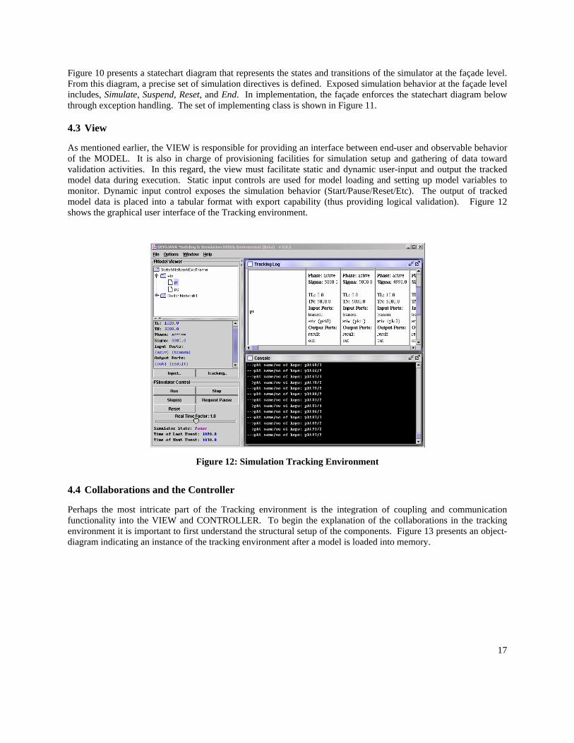
4.3 View
As mentioned earlier, the VIEW is responsible for providing an interface between end-user and observable behavior of the MODEL. It is also in charge of provisioning facilities for simulation setup and gathering of data toward validation activities. In this regard, the view must facilitate static and dynamic user-input and output the tracked model data during execution. Static input controls are used for model loading and setting up model variables to monitor. Dynamic input control exposes the simulation behavior (Start/Pause/Reset/Etc). The output of tracked model data is placed into a tabular format with export capability (thus providing logical validation). Figure 12 shows the graphical user interface of the Tracking environment.
Figure 12: Simulation Tracking Environment
4.4 Collaborations and the Controller
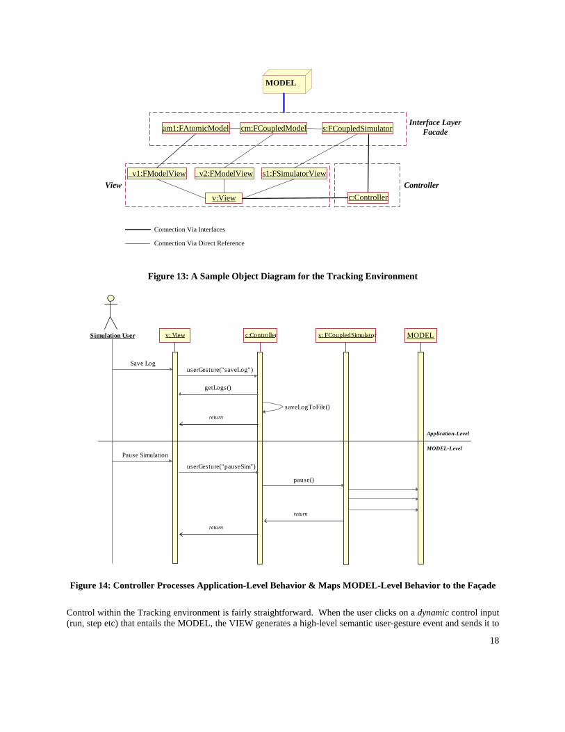
Perhaps the most intricate part of the Tracking environment is the integration of coupling and communication functionality into the VIEW and CONTROLLER. To begin the explanation of the collaborations in the tracking environment it is important to first understand the structural setup of the components. Figure 13 presents an object-diagram indicating an instance of the tracking environment after a model is loaded into memory.
18
v:View c:Controller
s:FCoupledSimulatorcm:FCoupledModelam1:FAtomicModel
_v1:FModelView _v2:FModelView s1:FSimulatorView
MODEL
Connection Via Interfaces
Interface LayerFacade
ControllerView
Connection Via Direct Reference
Figure 13: A Sample Object Diagram for the Tracking Environment
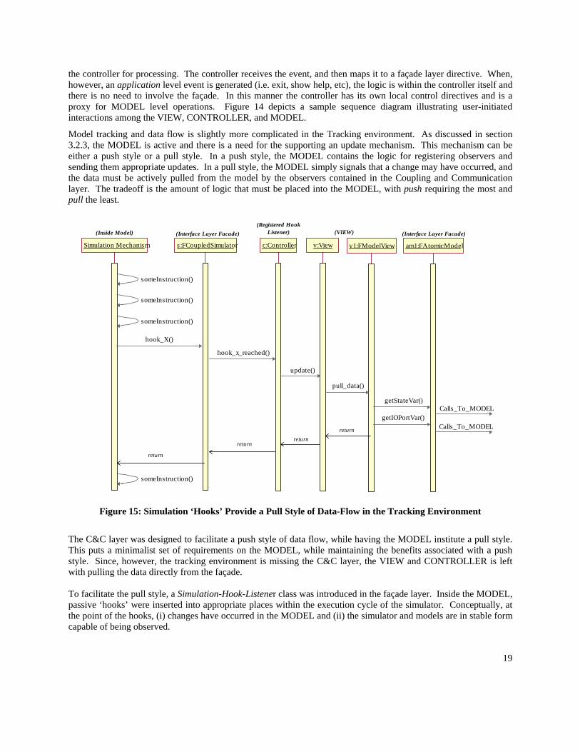
Figure 14: Controller Processes Application-Level Behavior & Maps MODEL-Level Behavior to the Façade
Control within the Tracking environment is fairly straightforward. When the user clicks on a dynamic control input (run, step etc) that entails the MODEL, the VIEW generates a high-level semantic user-gesture event and sends it to
userGesture("saveLog")
v: View s: FCoupledSimulator MODELSimulation User c:Controller
return
getLogs()
Save Log
saveLogToFile()return
Pause Simulation
userGesture("pauseSim")
pause()
return
Application-Level
MODEL-Level
19
the controller for processing. The controller receives the event, and then maps it to a façade layer directive. When, however, an application level event is generated (i.e. exit, show help, etc), the logic is within the controller itself and there is no need to involve the façade. In this manner the controller has its own local control directives and is a proxy for MODEL level operations. Figure 14 depicts a sample sequence diagram illustrating user-initiated interactions among the VIEW, CONTROLLER, and MODEL.
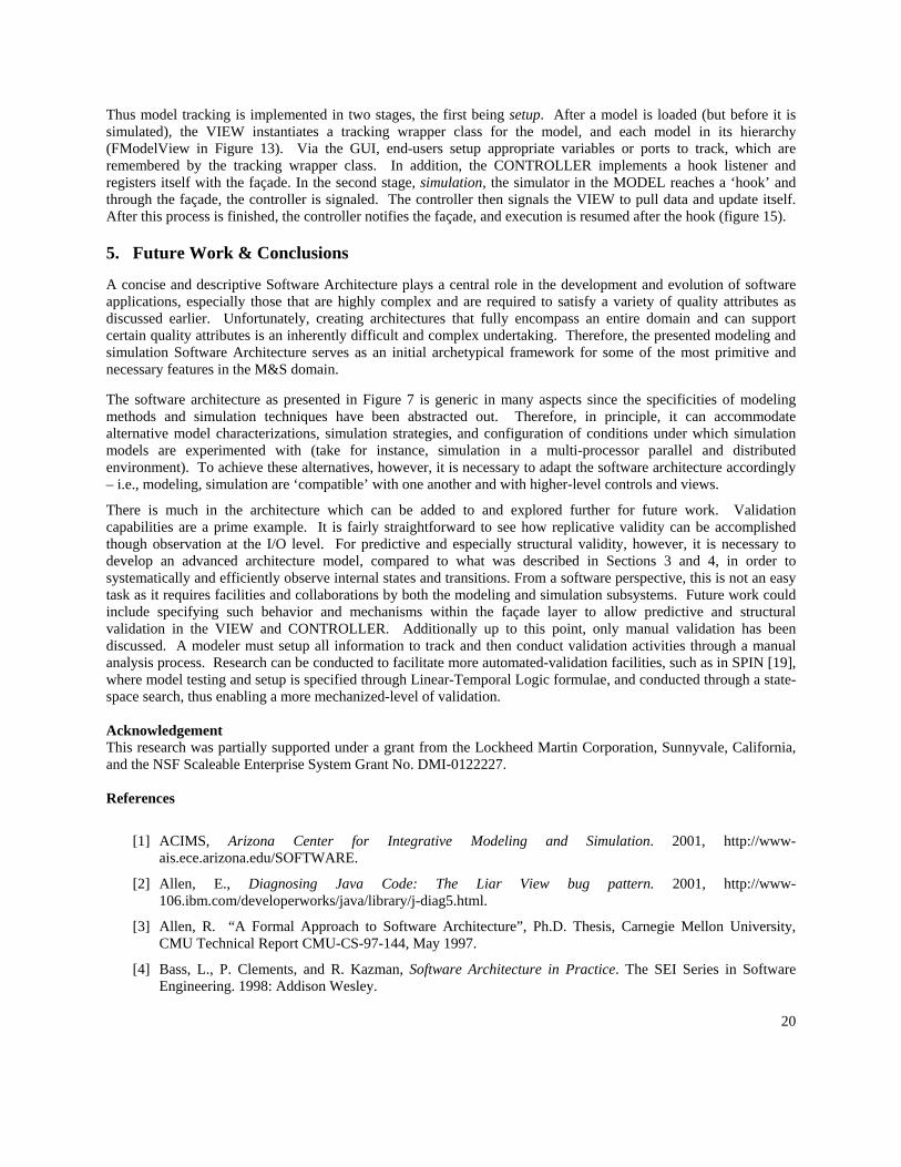
Model tracking and data flow is slightly more complicated in the Tracking environment. As discussed in section 3.2.3, the MODEL is active and there is a need for the supporting an update mechanism. This mechanism can be either a push style or a pull style. In a push style, the MODEL contains the logic for registering observers and sending them appropriate updates. In a pull style, the MODEL simply signals that a change may have occurred, and the data must be actively pulled from the model by the observers contained in the Coupling and Communication layer. The tradeoff is the amount of logic that must be placed into the MODEL, with push requiring the most and pull the least.
hook_x_reached()
Simulation Mechanism c:Controllers:FCoupledSimulator
return
someInstruction()
hook_X()
return
(Inside Model)
someInstruction()
someInstruction()
(Interface Layer Facade)(Registered Hook
Listener)
v:View v1:FModelView am1:FAtomicModel
update()
pull_data()
getStateVar()
getIOPortVar()
return
return
someInstruction()
(Interface Layer Facade)(VIEW)
Calls_To_MODEL
Calls_To_MODEL
Figure 15: Simulation ‘Hooks’ Provide a Pull Style of Data-Flow in the Tracking Environment
The C&C layer was designed to facilitate a push style of data flow, while having the MODEL institute a pull style. This puts a minimalist set of requirements on the MODEL, while maintaining the benefits associated with a push style. Since, however, the tracking environment is missing the C&C layer, the VIEW and CONTROLLER is left with pulling the data directly from the façade. To facilitate the pull style, a Simulation-Hook-Listener class was introduced in the façade layer. Inside the MODEL, passive ‘hooks’ were inserted into appropriate places within the execution cycle of the simulator. Conceptually, at the point of the hooks, (i) changes have occurred in the MODEL and (ii) the simulator and models are in stable form capable of being observed.
20
Thus model tracking is implemented in two stages, the first being setup. After a model is loaded (but before it is simulated), the VIEW instantiates a tracking wrapper class for the model, and each model in its hierarchy (FModelView in Figure 13). Via the GUI, end-users setup appropriate variables or ports to track, which are remembered by the tracking wrapper class. In addition, the CONTROLLER implements a hook listener and registers itself with the façade. In the second stage, simulation, the simulator in the MODEL reaches a ‘hook’ and through the façade, the controller is signaled. The controller then signals the VIEW to pull data and update itself. After this process is finished, the controller notifies the façade, and execution is resumed after the hook (figure 15).
5. Future Work & Conclusions
A concise and descriptive Software Architecture plays a central role in the development and evolution of software applications, especially those that are highly complex and are required to satisfy a variety of quality attributes as discussed earlier. Unfortunately, creating architectures that fully encompass an entire domain and can support certain quality attributes is an inherently difficult and complex undertaking. Therefore, the presented modeling and simulation Software Architecture serves as an initial archetypical framework for some of the most primitive and necessary features in the M&S domain.
The software architecture as presented in Figure 7 is generic in many aspects since the specificities of modeling methods and simulation techniques have been abstracted out. Therefore, in principle, it can accommodate alternative model characterizations, simulation strategies, and configuration of conditions under which simulation models are experimented with (take for instance, simulation in a multi-processor parallel and distributed environment). To achieve these alternatives, however, it is necessary to adapt the software architecture accordingly – i.e., modeling, simulation are ‘compatible’ with one another and with higher-level controls and views.
There is much in the architecture which can be added to and explored further for future work. Validation capabilities are a prime example. It is fairly straightforward to see how replicative validity can be accomplished though observation at the I/O level. For predictive and especially structural validity, however, it is necessary to develop an advanced architecture model, compared to what was described in Sections 3 and 4, in order to systematically and efficiently observe internal states and transitions. From a software perspective, this is not an easy task as it requires facilities and collaborations by both the modeling and simulation subsystems. Future work could include specifying such behavior and mechanisms within the façade layer to allow predictive and structural validation in the VIEW and CONTROLLER. Additionally up to this point, only manual validation has been discussed. A modeler must setup all information to track and then conduct validation activities through a manual analysis process. Research can be conducted to facilitate more automated-validation facilities, such as in SPIN [19], where model testing and setup is specified through Linear-Temporal Logic formulae, and conducted through a state-space search, thus enabling a more mechanized-level of validation. Acknowledgement This research was partially supported under a grant from the Lockheed Martin Corporation, Sunnyvale, California, and the NSF Scaleable Enterprise System Grant No. DMI-0122227. References
[1] ACIMS, Arizona Center for Integrative Modeling and Simulation. 2001, http://www-ais.ece.arizona.edu/SOFTWARE.
[2] Allen, E., Diagnosing Java Code: The Liar View bug pattern. 2001, http://www-106.ibm.com/developerworks/java/library/j-diag5.html.
[3] Allen, R. “A Formal Approach to Software Architecture”, Ph.D. Thesis, Carnegie Mellon University, CMU Technical Report CMU-CS-97-144, May 1997.
[4] Bass, L., P. Clements, and R. Kazman, Software Architecture in Practice. The SEI Series in Software Engineering. 1998: Addison Wesley.
21
[5] Booch, G., Object-Oriented Design with Applications. 1994, Redwood City, CA: Benjamin/Cummings.
[6] Booch, G., I. Jacobson, and J. Rumbaugh, The Unified Modeling Language User Guide. 1998: Addison-Wesley. 482.
[7] Burbeck, S., Applications Programming in Smalltalk-80(TM): How to use Model-View-Controller (MVC). 1992, http://st-www.cs.uiuc.edu/users/smarch/st-docs/mvc.html.
[8] Cellier, F.E., Continuous System Modeling. 1991: Springer Verlag.
[9] Fishwick, P.A., Simulation Model Design and Execution: Building Digital Worlds. 1995: Prentice Hall
[10] Gamma, E., R. Helm, R. Johnson, J. Vlissides, Design Patterns: Elements of Reusable Object-Oriented Software. 1994: Addison Wesley.
[11] HLA/RTI, https://www.dmso.mil/public/, visited Sept. 2003.
[12] Java BluePrints, Model-View-Controller. 2003: http://java.sun.com/blueprints/patterns/MVC-detailed.html
[13] Mesarovic, M.D., Y. Takahara, Abstract Systems Theory, Springer-Verlag, New York, 1989.
[14] Mohan, S. “Measuring Structural Complexities of Modular, Hierarchical Large-scale Models”, Master Thesis, Computer Science and Engineering, Arizona State University, Tempe, AZ, August, 2003.
[15] Park, S., B.P. Zeigler, H.S. Sarjoughian, (2001), “Interface for Scalable DEVS and Distributed Container Object Specifications”, IEEE International Conference on Systems, Man, and Cybernetics, October, Vol. 5, pp. 3075-80, Tucson, AZ, USA.
[16] Sarjoughian, H.S., B.P. Zeigler, “DEVS and HLA: Complementary Paradigms for M&S?”, Transactions of the Society for Computer Simulation, Vol. 17, No. 4, pp. 187-197, 2000.
[17] Sarjoughian, H.S., F.E. Cellier, Discrete Event Modeling & Simulation Technologies: A Tapestry of Systems and AI-based Theories and Methodologies for Modeling and Simulation, Springer Verlag, 2001.
[18] Sarjoughian, H.S, “An Approach for Scaleable Model Representation and Management Methodology”, in preparation.
[19] SPIN, http://spinroot.com/spin/whatispin.html, visited Sept. 2003.
[20] Wymore, W.A., Model-based Systems Engineering: An Introduction to the Mathematical Theory of Discrete Systems and to the Tricotyledon Theory of System Design, CRC, Boca Raton, 1993.
[21] Zeigler, B.P., H. Praehofer, and T.G. Kim, Theory of Modeling and Simulation: Integrating Discrete Event and Continuous Complex Dynamic Systems. Second Edition ed. 2000: Academic Press.