Embed Size (px)
Citation preview

1
Lecturer:Henry Muccini
Assistant Professor, Computer Science Department University of L'Aquila - Italy
[email protected][www.di.univaq.it/muccini] – [www.HenryMuccini.com]
Software Architecture-based Testing and Model-checking- ECI 2005, University of Buenos Aires -
Course Web-site: [www.di.univaq.it/muccini/ECI05/]
Lecture 5: Model-Checking driven Testing
2SEA Group
© 2005 by H. Muccini / ECI 2005 CourseSEA GroupSEA Group
Copyright Notice
» The material in these slides may be freely reproduced and distributed, partially or totally, as far as an explicit referenceor acknowledge to the material author is preserved.
Henry Muccini
3SEA Group
© 2005 by H. Muccini / ECI 2005 CourseSEA GroupSEA Group
Acknowledgment
» This work is joined with Patrizio Pelliccione (University of L’Aquila), Pierluigi Pierini (Siemens CNX), and Antonio Bucchiarone (ISTI – CNR)
» Published in ITM 2004, Lecture Notes in Computer Science, LNCS, vol. 3236, pp. 351 - 365 (2004).
2
4SEA Group
© 2005 by H. Muccini / ECI 2005 CourseSEA GroupSEA Group
Agenda
» Introduction and Motivations:
- ModTest and TeStor
» ModTest in Siemens C.N.X.
» Challenges and Future Work
5SEA Group
© 2005 by H. Muccini / ECI 2005 CourseSEA GroupSEA Group
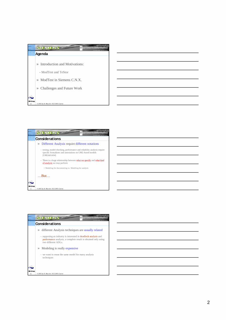
Considerations» Different Analysis require different notations
- testing, model-checking, performance and reliability analysis requirespecific formalisms and annotations on UML-based models[UML&SA04]
- There is a huge relationship between what we specify and what kindof analysis we may perform
> Modeling for documenting vs. Modeling for analysis
…But…
6SEA Group
© 2005 by H. Muccini / ECI 2005 CourseSEA GroupSEA Group
Considerations
» different Analysis techniques are usually related
- supposing an industry is interested in deadlock analysis and performance analysis, a complete result is obtained only using two different ADLs.
» Modeling is really expensive
- we want to reuse the same model for many analysistechniques
3
7SEA Group
© 2005 by H. Muccini / ECI 2005 CourseSEA GroupSEA Group
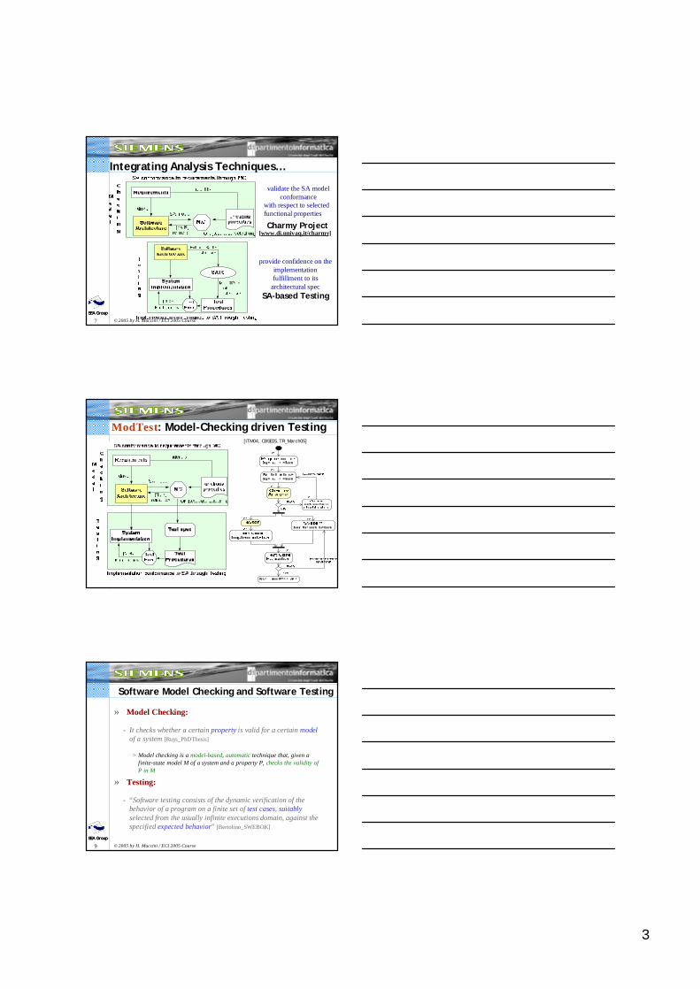
Integrating Analysis Techniques…
provide confidence on the implementation fulfillment to its
architectural specSA-based Testing
Charmy Project
validate the SA model conformance
with respect to selected functional properties
[www.di.univaq.it/charmy]
8SEA Group
© 2005 by H. Muccini / ECI 2005 CourseSEA GroupSEA Group
ModTest: Model-Checking driven Testing[ITM04, CBSE05,TR_March05]
9SEA Group
© 2005 by H. Muccini / ECI 2005 CourseSEA GroupSEA Group
Software Model Checking and Software Testing
» Model Checking:
- It checks whether a certain property is valid for a certain modelof a system [Ruys_PhDThesis]
> Model checking is a model-based, automatic technique that, given a finite-state model M of a system and a property P, checks the validity of P in M
» Testing:
- “Software testing consists of the dynamic verification of the behavior of a program on a finite set of test cases, suitablyselected from the usually infinite executions domain, against the specified expected behavior” [Bertolino_SWEBOK]
4
10SEA Group
© 2005 by H. Muccini / ECI 2005 CourseSEA GroupSEA Group
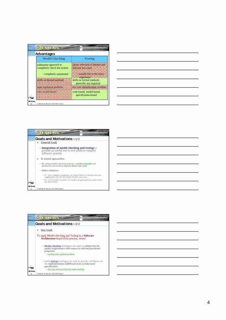
Advantages
skills on formal methodsgenerally not required
skills on formal methods
test case identification problemstate explosion problem
code-based, model-based, specification-based
only model-based
clever selection of limited and relevant test cases
- usually left to the testerexperience
exhaustive approach tocompletely check the system
- completely automated
TestingModel Checking
11SEA Group
© 2005 by H. Muccini / ECI 2005 CourseSEA GroupSEA Group
Goals and Motivations > 1/2» General Goal:
-- integrationintegration of of modelmodel--checkingchecking and and testingtesting toprovide an useful tool to test modern complexsoftware systems
» In related approaches:
- By using model-checking features, counter-examples are produced, successively used to derive test cases
- Main Limitations:
> P1 : due to models complexity, the model checker techniques become inapplicable, thus not allowing to identify test cases;
> P2 : even on little examples, the number of generated test cases causes the intractability
12SEA Group
© 2005 by H. Muccini / ECI 2005 CourseSEA GroupSEA Group
Goals and Motivations > 2/2
» Our Goal:
To apply Model-checking and Testing in a SoftwareArchitecture-based (SA) process, where:
> Model-checking techniques are used to validate the SA model conformance with respect to selected functionalproperties+ avoiding state explosion problem
> while testing techniques are used to provide confidence on the implementation fulfillment to its architecturalspecification+ Test case selection driven by model-checking
5
13SEA Group
© 2005 by H. Muccini / ECI 2005 CourseSEA GroupSEA Group
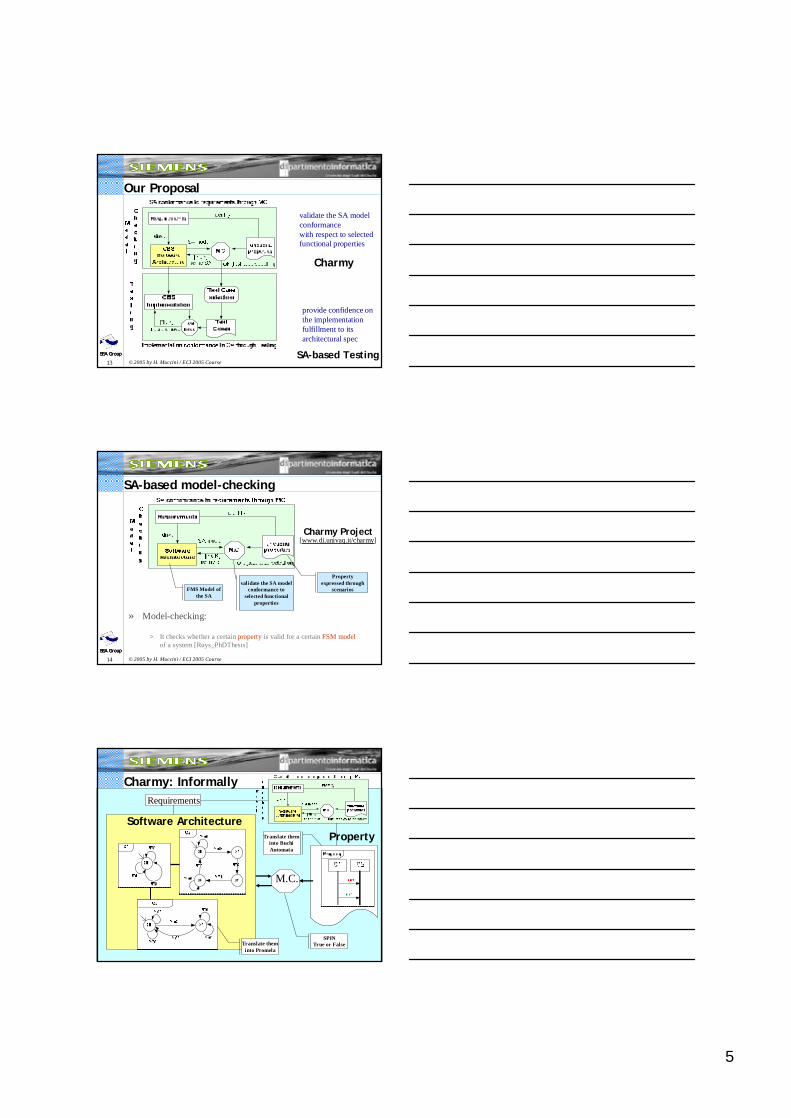
Our Proposal
Charmy
validate the SA model conformance with respect to selected functional properties
provide confidence on the implementation fulfillment to its architectural spec
SA-based Testing
14SEA Group
© 2005 by H. Muccini / ECI 2005 CourseSEA GroupSEA Group
SA-based model-checking
Charmy Project[www.di.univaq.it/charmy]
» Model-checking:
> It checks whether a certain property is valid for a certain FSM modelof a system [Ruys_PhDThesis]
FMS Model of the SA
Propertyexpressed through
scenariosvalidate the SA model
conformance to selected functional
properties
15SEA Group
© 2005 by H. Muccini / ECI 2005 CourseSEA GroupSEA Group
Software ArchitectureProperty
M.C.
Requirements
Charmy: Informally
SPINTrue or FalseTranslate them
into Promela
Translate theminto Buchi Automata
6
16SEA Group
© 2005 by H. Muccini / ECI 2005 CourseSEA GroupSEA Group
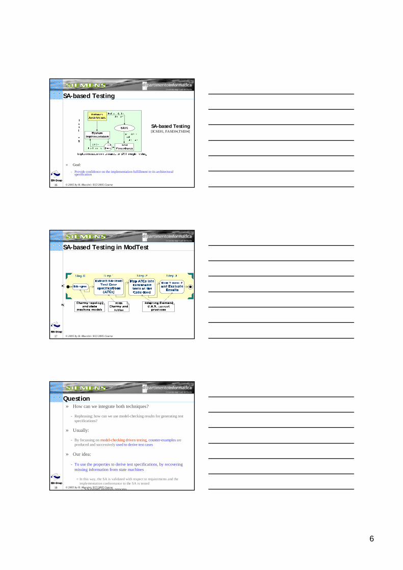
SA-based Testing
» Goal:
- Provide confidence on the implementation fulfillment to its architectural specification
SA-based Testing[ICSE01, FASE04,TSE04]
17SEA Group
© 2005 by H. Muccini / ECI 2005 CourseSEA GroupSEA Group
SA-based Testing in ModTest
18SEA Group
© 2005 by H. Muccini / ECI 2005 CourseSEA GroupSEA Group
Question» How can we integrate both techniques?
- Rephrasing: how can we use model-checking results for generating test specifications?
» Usually:
- By focussing on model-checking driven testing, counter-examples are produced and successively used to derive test cases
» Our idea:
- To use the properties to derive test specifications, by recoveringmissing information from state machines
> In this way, the SA is validated with respect to requirements and the implementation conformance to the SA is tested
- SA-based analysis process
7
19SEA Group
© 2005 by H. Muccini / ECI 2005 CourseSEA GroupSEA Group
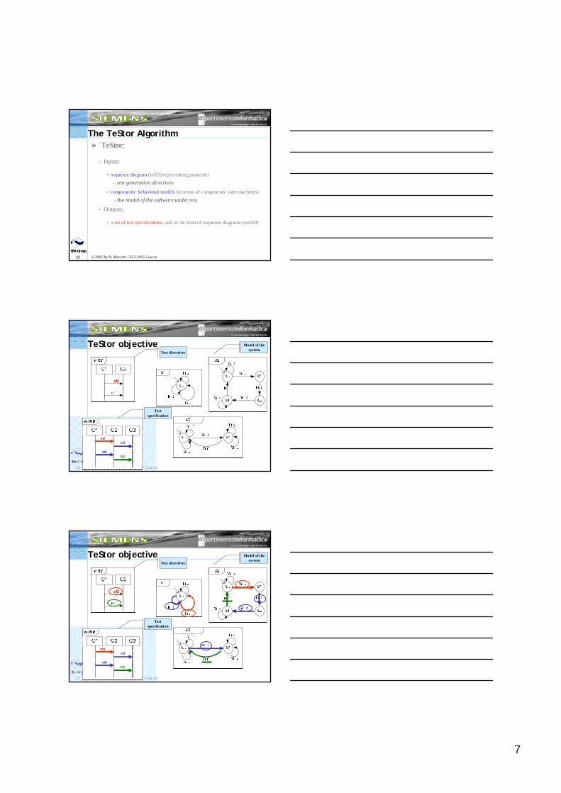
The TeStor Algorithm» TeStor:
- Inputs:
> sequence diagram (inSD) representing properties- test generation directives
> components’ behavioral models (in terms of components' state machines),
- the model of the software under test- Outputs:
> a set of test specifications, still in the form of sequence diagrams (outSD)
20SEA Group
© 2005 by H. Muccini / ECI 2005 CourseSEA GroupSEA Group
TeStor objective Model of the system
Test directives
m9m3
m8m1
Test specification
21SEA Group
© 2005 by H. Muccini / ECI 2005 CourseSEA GroupSEA Group
TeStor objective
m9m3
m8m1
Model of the system
Test directives
Test specification

8
22SEA Group
© 2005 by H. Muccini / ECI 2005 CourseSEA GroupSEA Group
How TeStor can achieve this goal
» How TeStor could work:
- Parallel composition of the state-machines models, and theirtraversal (like model-checkers), or
- Challenge: to avoid parallel composition
> To limit state explosion problems…
23SEA Group
© 2005 by H. Muccini / ECI 2005 CourseSEA GroupSEA Group
The Algorithm
» The TeStor algorithm can be split into two macro-steps:
- State machines (SM) Linearization
> Decomposes SM in a set of linear traces
- Test Sequence Generation
> Looks at each linearized trace in order to identify the sup-trace of the inSD.
> This macro-step is composed by a Validation part, which checkswhen and how sup-traces need to be combined to produce theoutSD.
> The Merge algorithm glues together the validated traces
24SEA Group
© 2005 by H. Muccini / ECI 2005 CourseSEA GroupSEA Group
Linearization» Starting from the initial state in the components’ state diagrams;
- It creates a trace at any time a state with a branch is reached or analready visited state is reached
» The algorithm is iterated, starting from the previously reached state, until unvisited states still exist.
S0 à S0m8
S0 à S1à S2à S3m9 m3 m10
S3 à S3m9
S3 à S4à S5à S0m8 m1 m7
S1
S2S3S4
S5
9
25SEA Group
© 2005 by H. Muccini / ECI 2005 CourseSEA GroupSEA Group
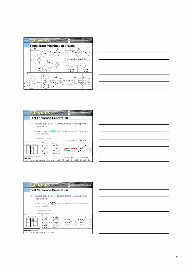
From State Machines to Traces
26SEA Group
© 2005 by H. Muccini / ECI 2005 CourseSEA GroupSEA Group
Test Sequence Generation
» Starting from the traces generated from each componentstate machine
- For each message “mi” in the inSD, TeStor identifies those traceswhich contain it
> Validate algorithm
Property
e) Property to be verified
C3 C2 C1 C4
m9m3
m10
m8
m1
m7
C2’s i.s. = S0 C3’s i.s. = S0
S0 –m9> S1S0 --m9-> S1 -- m3->S2 --m10->S3 --m9->S3
S0 –m9> S0
27SEA Group
© 2005 by H. Muccini / ECI 2005 CourseSEA GroupSEA Group
Test Sequence Generation
» Starting from the traces generated from each componentstate machine
- For each message “mi” in the inSD, TeStor identifies those traceswhich contain it
> Validate algorithm
> Merge algoritmProperty
e) Property to be verified
C3 C2 C1 C4
m9m3
m10
m8
m1
m7
10
28SEA Group
© 2005 by H. Muccini / ECI 2005 CourseSEA GroupSEA Group
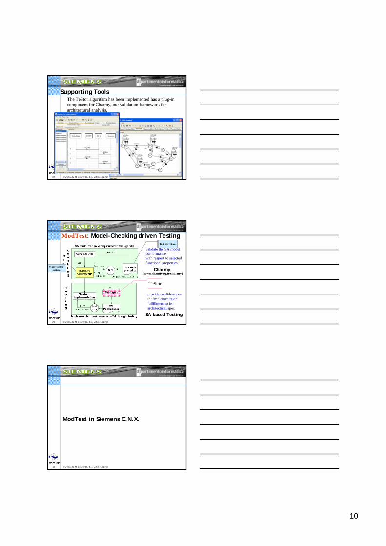
Supporting ToolsThe TeStor algorithm has been implemented has a plug-incomponent for Charmy, our validation framework forarchitectural analysis.
29SEA Group
© 2005 by H. Muccini / ECI 2005 CourseSEA GroupSEA Group
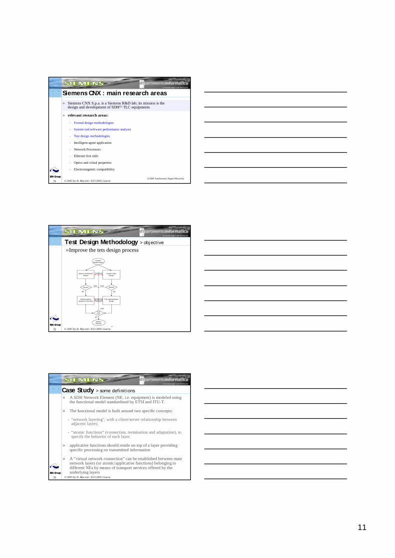
ModTest: Model-Checking driven Testing
Charmy
validate the SA model conformance with respect to selected functional properties
SA-based Testing
provide confidence on the implementation fulfillment to its architectural spec
TeStor
[www.di.univaq.it/charmy]
Model of the system
Test directives
30SEA Group
© 2005 by H. Muccini / ECI 2005 CourseSEA GroupSEA Group
ModTest in Siemens C.N.X.
11
31SEA Group
© 2005 by H. Muccini / ECI 2005 CourseSEA GroupSEA Group
Siemens CNX : main research areas» Siemens CNX S.p.a. is a Siemens R&D lab; its mission is the
design and development of SDH(1) TLC equipments
» relevant research areas:
- Formal design methodologies
- System and software performance analysis
- Test design methodologies
- Intelligent agent application
- Network Processors
- Ethernet first mile
- Optics and cristal properties
- Electromagnetic compatibility
1) SDH Synchronous Digital Hierarchy
32SEA Group
© 2005 by H. Muccini / ECI 2005 CourseSEA GroupSEA Group
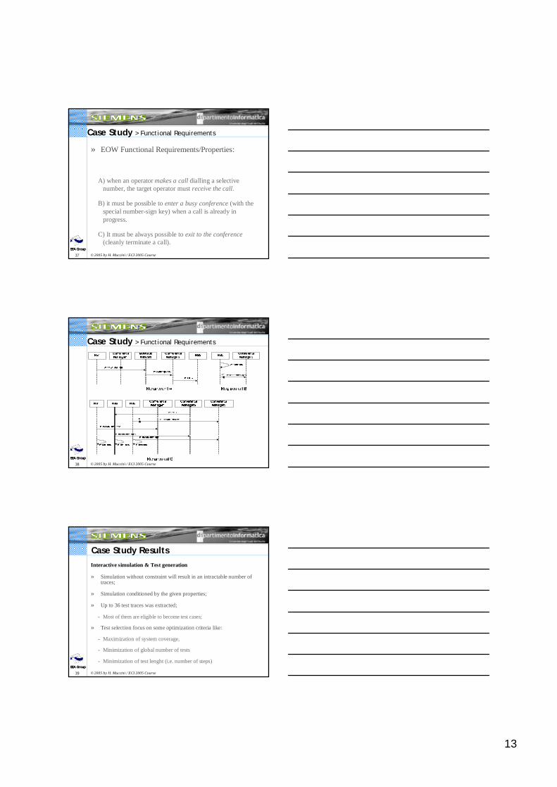
System ArchitectureDesign
System TestsDesign
feedbacks
ImplementationEquipment Develop
Test ImplelemtationDesign
Review Review
TestExec
NOK
OKOK
SystemRequirements
NOKNOK
SystemRelease
OK
ModificationRequests
a
System ArchitectureDesign
SystemRequirements
ModelCheck
Implementation/Equipment Develop
Test GenerationEngine
TestExec
NOK
OK
NOK
OK
SystemRelease
b
Test Design Methodology > objective
»Improve the tets design process
33SEA Group
© 2005 by H. Muccini / ECI 2005 CourseSEA GroupSEA Group
Case Study > some definitions» A SDH Network Element (NE, i.e. equipment) is modeled using
the functional model standardized by ETSI and ITU-T.
» The functional model is built around two specific concepts:
- “network layering", with a client/server relationship between adjacent layers;
- “atomic functions“ (connection, termination and adaptation), to specify the behavior of each layer.
» applicative functions should reside on top of a layer providing specific processing on transmitted information
» A “virtual network connection” can be established between mate network layers (or atomic/applicative functions) belonging to different NEs by means of transport services offered by the underlying layers
12
34SEA Group
© 2005 by H. Muccini / ECI 2005 CourseSEA GroupSEA Group
Case Study > some definitions
35SEA Group
© 2005 by H. Muccini / ECI 2005 CourseSEA GroupSEA Group
Case Study > EOW architecture
» The EOW supports a telephone link between NEs using dedicated voice channels defined on the SDH frame (i.e. the “EOW SubNetwork” [eowSN]);
» An EOW node consists of:
- A “handset” (HS) that manage the physical phone device;
- a “conference manager” (CM) that control the handset connection to the EOW subnetwork;
eowSNHS
CM
HS
CM
HS
CM
EOWNode
36SEA Group
© 2005 by H. Muccini / ECI 2005 CourseSEA GroupSEA Group
Case Study > EOW components
HS1
CM1
eowSN
localNumSign1
call1callRequest
callRequest
callRequest
eowKeyDigit
eowKeyDigit
eowKeyDigit
HS2
CM2localNumSign2
call2
HS3
CM3localNumSign3
call3
Init Configconfig
IdleonHook
Congestion
offH
o o k onHook
Ringing
InConference
Dialing
Check
Busy
?call
time o
ut
timeout
offHook
onH ook
[cbu
sy=
=tru
e]
[cbusy==false]
time ou t
o nHook
?calloffHook
onHook
!lo ca lNumS ign
?call
eowKeyDig it (digit,numbe r)
!loc alNumS ign
Handset (HS)
S1?eowKeyDigit(digit,number)
S2
!callRequest(digit,number)
eowSubnetwork
S4
S3
S2S1?callRequest(digit,number)
? lo ca l N umS ig n /c b u sy = f a ls e
[(digit==x)&&(number!=1)]/!callRequest(digit,number)
[ (di g i t= = x )& & (n u m b e r!=
1 )] / !c a l l/ c
b u s y= t rue
! callRequest(dig it,number)
[digi
t==0]
/!call
Conference Manager (CM)
13
37SEA Group
© 2005 by H. Muccini / ECI 2005 CourseSEA GroupSEA Group
Case Study > Functional Requirements
» EOW Functional Requirements/Properties:
A) when an operator makes a call dialling a selectivenumber, the target operator must receive the call.
B) it must be possible to enter a busy conference (with the special number-sign key) when a call is already in progress.
C) It must be always possible to exit to the conference(cleanly terminate a call).
38SEA Group
© 2005 by H. Muccini / ECI 2005 CourseSEA GroupSEA Group
Case Study > Functional Requirements
39SEA Group
© 2005 by H. Muccini / ECI 2005 CourseSEA GroupSEA Group
Case Study ResultsInteractive simulation & Test generation
» Simulation without constraint will result in an intractable number of traces;
» Simulation conditioned by the given properties;
» Up to 36 test traces was extracted;
- Most of them are eligible to become test cases;
» Test selection focus on some optimization criteria like:
- Maximization of system coverage,
- Minimization of global number of tests
- Minimization of test lenght (i.e. number of steps)
14
40SEA Group
© 2005 by H. Muccini / ECI 2005 CourseSEA GroupSEA Group
Some ConsiderationsAdvantages:
» Model complexity and the state explosion reduction obtained by: SA-level model chekcing, iterative approach and abstraction ;
» Charmy → easy to use, practical, approach to model-checking, hidingthe modeling complexity;
» interactive simulation → we may identify traces of interest for testingthe whole system or just a relevant subsystem.
» test specifications are identified from the architectural model (notfrom requirements)
- Easiest alignment between SA and Test specifications;
- Easiest control of the design steps and evolution
41SEA Group
© 2005 by H. Muccini / ECI 2005 CourseSEA GroupSEA Group
Some Considerations
Limitations:
» The Test Generator Engine can be automated; itsimplementation is in progress.
» The executable tests implementation from the generatedtest specifications is not automated yet. We approach thispoint with the aim to automate also this step.
» Models dimension and complexity still remain an issue, even if the iterative approach reduces the state explosionproblem.
42SEA Group
© 2005 by H. Muccini / ECI 2005 CourseSEA GroupSEA Group
Challenges
15
43SEA Group
© 2005 by H. Muccini / ECI 2005 CourseSEA GroupSEA Group
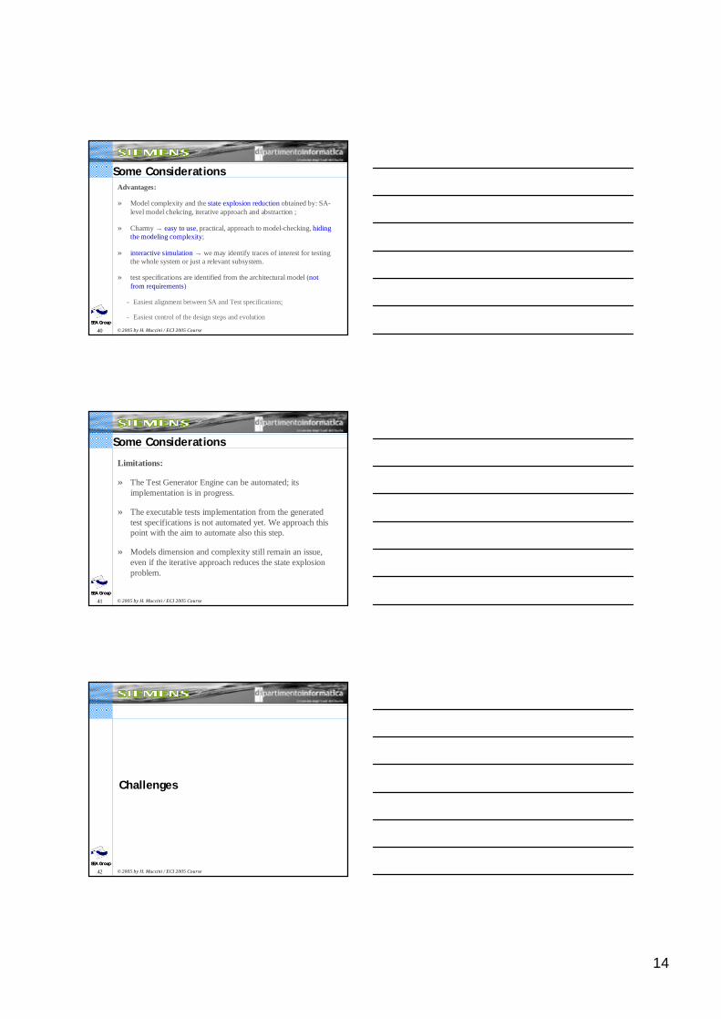
Challenge: SA-centric Analysis Process
44SEA Group
© 2005 by H. Muccini / ECI 2005 CourseSEA GroupSEA Group
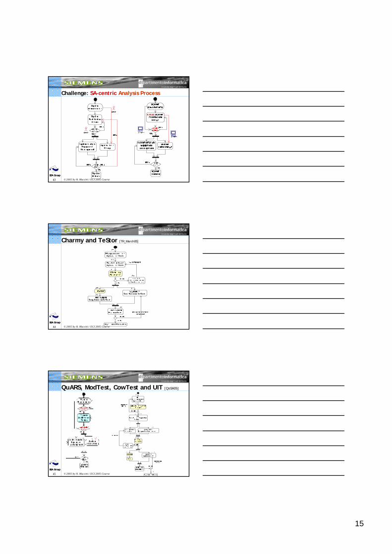
Charmy and TeStor [TR_March05]
45SEA Group
© 2005 by H. Muccini / ECI 2005 CourseSEA GroupSEA Group
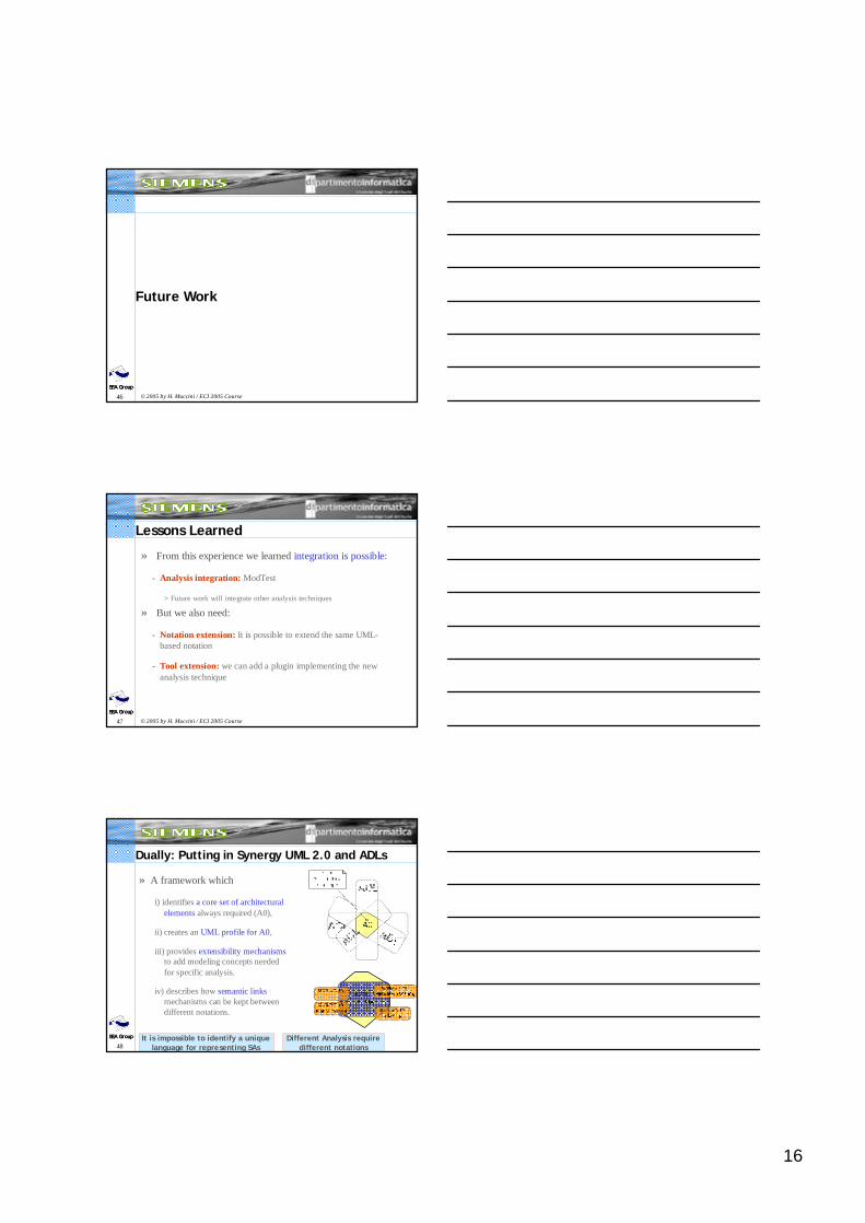
QuARS, ModTest, CowTest and UIT [QoSA05]
16
46SEA Group
© 2005 by H. Muccini / ECI 2005 CourseSEA GroupSEA Group
Future Work
47SEA Group
© 2005 by H. Muccini / ECI 2005 CourseSEA GroupSEA Group
Lessons Learned
» From this experience we learned integration is possible:
- Analysis integration: ModTest
> Future work will integrate other analysis techniques
» But we also need:
- Notation extension: It is possible to extend the same UML-based notation
- Tool extension: we can add a plugin implementing the new analysis technique
48SEA Group
© 2005 by H. Muccini / ECI 2005 CourseSEA GroupSEA Group
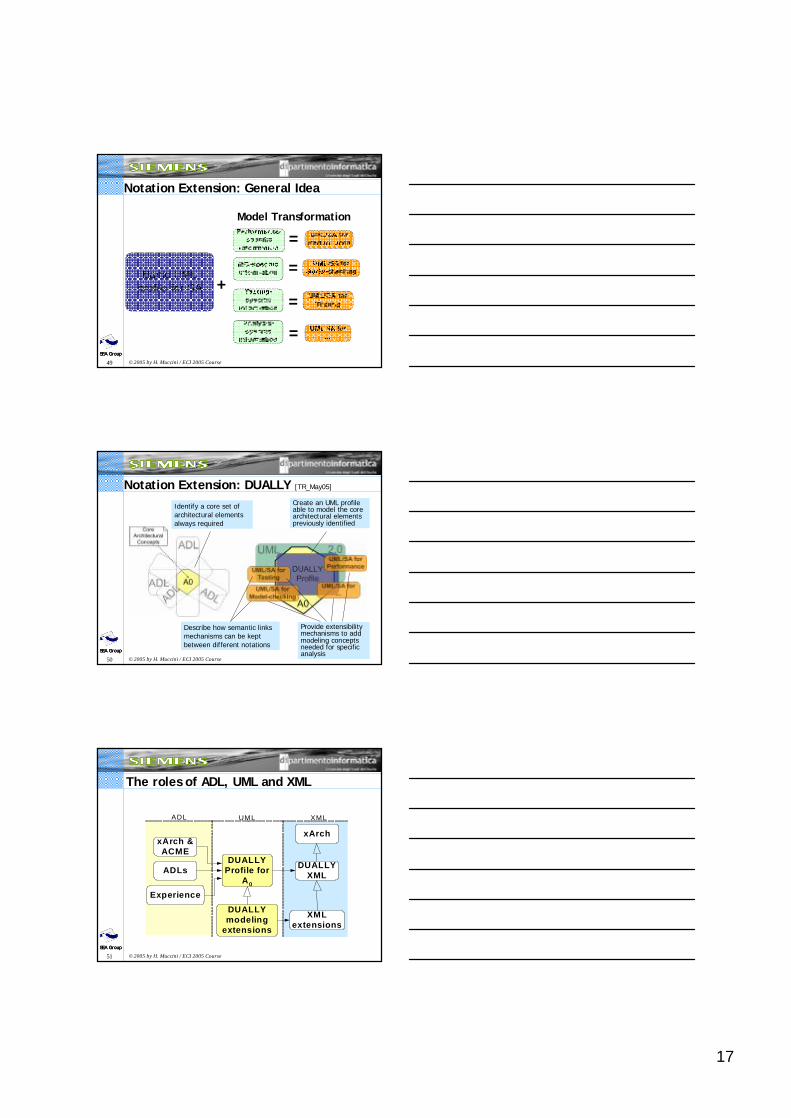
Dually: Putting in Synergy UML 2.0 and ADLs
» A framework which
i) identifies a core set of architectural elements always required (A0),
ii) creates an UML profile for A0,
iii) provides extensibility mechanismsto add modeling concepts needed for specific analysis.
iv) describes how semantic linksmechanisms can be kept between different notations.
It is impossible to identify a unique language for representing SAs
Different Analysis requiredifferent notations
17
49SEA Group
© 2005 by H. Muccini / ECI 2005 CourseSEA GroupSEA Group
Notation Extension: General Idea
+
=
=
=
=
Model Transformation
50SEA Group
© 2005 by H. Muccini / ECI 2005 CourseSEA GroupSEA Group
Identify a core set of architectural elements always required
Create an UML profile able to model the core architectural elements previously identified
Provide extensibility mechanisms to add modeling concepts needed for specific analysis
Describe how semantic links mechanisms can be kept between different notations
Notation Extension: DUALLY [TR_May05]
51SEA Group
© 2005 by H. Muccini / ECI 2005 CourseSEA GroupSEA Group
The roles of ADL, UML and XML
xArch
DUALLYProfile for
A0
ADL XMLUML
ADLs
DUALLYmodeling
extensions
XMLextensions
DUALLYXML
xArch &ACME
Experience
18
52SEA Group
© 2005 by H. Muccini / ECI 2005 CourseSEA GroupSEA Group
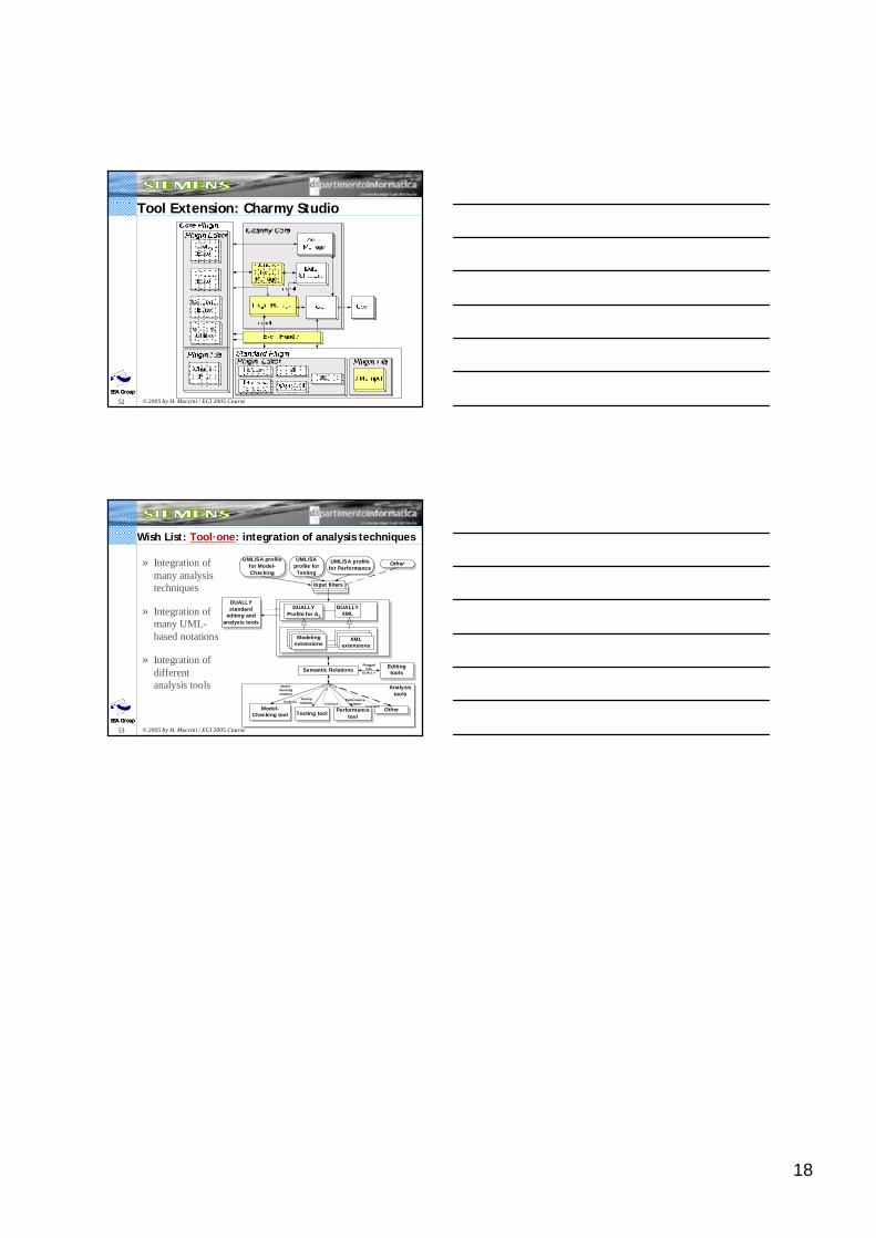
Tool Extension: Charmy Studio
53SEA Group
© 2005 by H. Muccini / ECI 2005 CourseSEA GroupSEA Group
Wish List: Tool·one: integration of analysis techniques
» Integration of many analysistechniques
» Integration of many UML-based notations
» Integration of differentanalysis tools
UML/SA profilefor Model-Checking
Semantic Relations
UML/SAprofile forTesting
Other
Testing toolOther
Input filters
Model-Checking tool
DUALLYXML
Model-checkingnotation
Testingnotation
UML/SA profilefor Performance
DUALLYProfile for A0
DUALLYstandard
editing andanalysis tools
Performancetool
Performancenotation
XMLextensions
Modelingextensions
Pluggedinto
DUALLY
Analysistools
Editingtools
feedback feedbackfeedback