Embed Size (px)
Citation preview

SoftRock RXTX Ensemble RX Mixer
William R. Robinson Jr. AJ4MC p1of 17 2011 All rights Reserved
Reference 1
Purpose and Function The Rx mixer is really two RX mixers with the LO inputs 90 degrees apart giving us a In-phase and Quadrature signals at or near the 0 Hz (direct Conversion) The LO clocks come from the local oscillator Dividers on QSD_CLK_0,1 and the two copies of the RF come from the two balanced outputs from T5. The mixer stage ("QSD" - Quadrature Sampling Detector) acts like two traditional direct conversion mixers operating in tandem. Each takes in half of the filtered RF from the bandpass filter stage and one of the quadrature center frequency signals, then "mixes"/down-converts them to with an output being the traditional mixer products, in this case, two (infra) audio frequency signals that represent the difference between the two inputs (RF and Local Oscillator). These two signals are referred to as the detected I (in-phase) and Q (Quadrature) signals and are fed into the high gain Op-Amps stage for amplification and delivery to the audio outputs. … The mixer chip (actually a commutating switch, clocked by the two QSD Clock signals from the Dividers Stage) outputs the product and difference signals of the incoming RF against the QSD clock. The effect is to down-convert the incoming RF into its quadrature analogues at frequencies ranging from 0 to roughly 100 kHz. These quadrature pairs from the RX Mixer, identifcal in all respects except phase, are fed to the RX OpAmp Stage. 1
SoftRock RXTX Ensemble RX Mixer
William R. Robinson Jr. AJ4MC p2of 17 2011 All rights Reserved
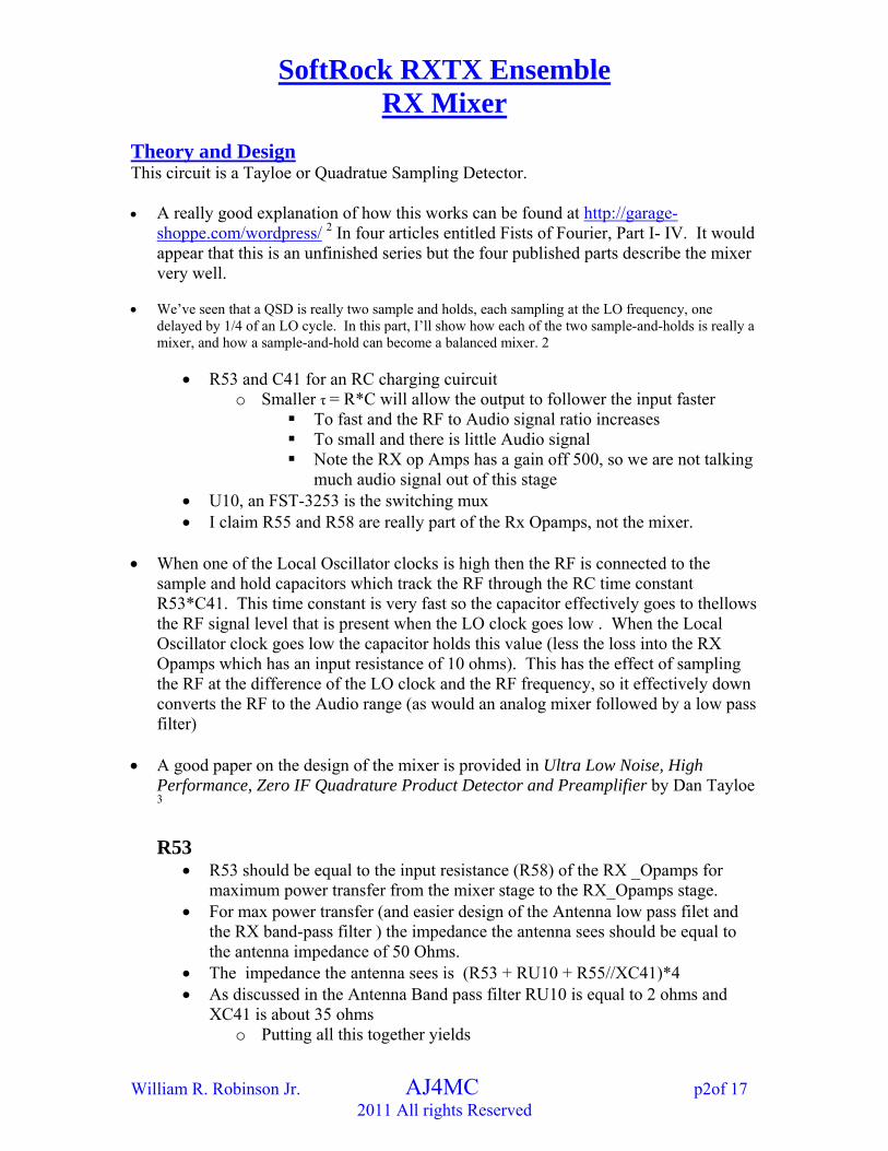
Theory and Design This circuit is a Tayloe or Quadratue Sampling Detector. A really good explanation of how this works can be found at http://garage-
shoppe.com/wordpress/ 2 In four articles entitled Fists of Fourier, Part I- IV. It would appear that this is an unfinished series but the four published parts describe the mixer very well.
We’ve seen that a QSD is really two sample and holds, each sampling at the LO frequency, one
delayed by 1/4 of an LO cycle. In this part, I’ll show how each of the two sample-and-holds is really a mixer, and how a sample-and-hold can become a balanced mixer. 2
R53 and C41 for an RC charging cuircuit o Smaller τ = R*C will allow the output to follower the input faster
To fast and the RF to Audio signal ratio increases To small and there is little Audio signal Note the RX op Amps has a gain off 500, so we are not talking
much audio signal out of this stage U10, an FST-3253 is the switching mux I claim R55 and R58 are really part of the Rx Opamps, not the mixer.
When one of the Local Oscillator clocks is high then the RF is connected to the
sample and hold capacitors which track the RF through the RC time constant R53*C41. This time constant is very fast so the capacitor effectively goes to thellows the RF signal level that is present when the LO clock goes low . When the Local Oscillator clock goes low the capacitor holds this value (less the loss into the RX Opamps which has an input resistance of 10 ohms). This has the effect of sampling the RF at the difference of the LO clock and the RF frequency, so it effectively down converts the RF to the Audio range (as would an analog mixer followed by a low pass filter)
A good paper on the design of the mixer is provided in Ultra Low Noise, High
Performance, Zero IF Quadrature Product Detector and Preamplifier by Dan Tayloe 3
R53
R53 should be equal to the input resistance (R58) of the RX _Opamps for maximum power transfer from the mixer stage to the RX_Opamps stage.
For max power transfer (and easier design of the Antenna low pass filet and the RX band-pass filter ) the impedance the antenna sees should be equal to the antenna impedance of 50 Ohms.
The impedance the antenna sees is (R53 + RU10 + R55//XC41)*4 As discussed in the Antenna Band pass filter RU10 is equal to 2 ohms and
XC41 is about 35 ohms o Putting all this together yields

SoftRock RXTX Ensemble RX Mixer
William R. Robinson Jr. AJ4MC p3of 17 2011 All rights Reserved
R53 + 2 + R53//35 = 50/4 Skipping the quadratics I get R53 = R55 = 5.64 Ohms 4
o Because we want the I and Q sides to be balanced, then high precession (1%) components are in order Digikey has three choices in stock at the time I write this
two are wire-wound and are not a good choice for RfF due to the inductance
The remaining part is $3.58 Perhaps this is why 10 ohms was chosen although a few
6.8 ohms are available that would appear to work
C41 The Mixer should have a band width greater than the 96KHz that the sound
cards are capable of using. Because we want a flat response in the area of interest (up to 96 Khz) it needs
to be much greater Reference 3 states actual detection bandwidth will be twice that of the
calculated low-pass filter as the the low-pass roll off will extend to both sides of the center detection frequency
Simulation shows that the value chosen 0.047 uF gives 1% attenuation at 48 KHz
Conversion Loss
Conversion loss of a mixer is equal to the ratio of the IF single sideband output to the RF input level 5
Conversion loss = - ) log( 20Vrf
Vif
Dan Tayloe suggests that the conversion loss should be about 0.9dB! 3 Isolation
The L to I isolation is the amount the LO drive level is attenuated when it is measured at the IF port 5
Isolation = )__
log( 20Vrf
ifatVrf

SoftRock RXTX Ensemble RX Mixer
William R. Robinson Jr. AJ4MC p4of 17 2011 All rights Reserved
Calculated Frequency (audio bandwidth)
RC
Fc2
1 6
41*532
1
CRFc
uF
Fc047.0*10*2
1
Fc = 338 Khz
Conversion Loss
Conversion loss = - ) log( 20Vrf
Vif
o I do not know of a way to calculate this value Dan Tayloe suggests that the conversion loss could be as low as 0.9dB! 3
Isolation
Isolation = )__
log( 20Vlo
ifatVlo
Isolation can also be measured from Rf to If but as rf is usually small LO to If is usually more important
o I do not know of a way to calculate this value

SoftRock RXTX Ensemble RX Mixer
William R. Robinson Jr. AJ4MC p5of 17 2011 All rights Reserved
Simulation
V1 = 7.1 MHz at 1 Vp-p V2 = 7.0 MHz at 1 Vp-p Note how the falling edge of Vswitch occurs at lower voltages of Vin as time
increases and Vout shows this trend. The output frequency is this the difference of the two frequencies 7.1 – 7.0
MHz = 100 Khz o 100 Khz is a high for the application but was chosen so that the user
could see the effect of the circuit
Rload is R55 and is 10 ohms The design is somewhat sensitive to Rload
Rload should be selected to match R53 for maximum power transfer. 7,8 o R53 also affects the RC timing constant o Rload also affects the gain of the Rx Opamps
The current values provide near the nominal 50 ohm load to the Antenna Low Pass Filter and the Rx Band Pass Filter 9
o The Plot below shows the time domain response with Rload varied from 2 to 20 ohms in 10 Ohm steps

SoftRock RXTX Ensemble RX Mixer
William R. Robinson Jr. AJ4MC p6of 17 2011 All rights Reserved
20 Ohms has the most magnitude Little effect on magnitude of Rf frequencies in Vout
v(out)[0]v(out)[1]v(out)[2]v(out)[3]v(out)[4]v(out)[5]v(out)[6]v(out)[7]v(out)[8]v(out)[9]
RX_mixer-Transient-41-Sweep-Graph
Time50.0048.000u46.000u44.000u42.000u40.000u38.000u36.000u34.000u32.000u30.000u28.000u26.000u24.000u22.000u20.000u
180.000m
160.000m140.000m120.000m100.000m
80.000m60.000m
40.000m20.000m
0.0-20.000m-40.000m
-60.000m-80.000m
-100.000m-120.000m-140.000m-160.000m
-180.000m
Component value selection
R53 and C41 o R53 and C41 form an RC charging circuit o Smaller time constants give increased audio signal but also increased
RF noise on the signal The RF noise grows faster than the Audio signal I do not how to select the optimal value, especially considering
that the Rx Opamps will filter out most of the RF The chart below shows the results for three different values of
C41 Similar results were found for varying values of R53
C41 in uF Vp-p at 10 Khz
mVolts Vp-p at 7 Mhz
mVolts 0.0047 340 150 0.047 200 9 0.47 155 2
Design Value
Frequency (audio bandwidth)
Fc =335.8 KHz

SoftRock RXTX Ensemble RX Mixer
William R. Robinson Jr. AJ4MC p7of 17 2011 All rights Reserved
vdb(out)
RX_mixer-Small Signal AC-36-Graph
Frequency100.000 1.000k 10.000k 100.000k 1.000
-99.000-99.500
-100.000
-100.500
-101.000
-101.500
-102.000
-102.500
-103.000-103.500
-104.000
-104.500
-105.000
-105.500
-106.000
-106.500
-107.000-107.500
-108.000
-108.500
-109.000
-109.500
-110.000
-110.500
Conversion Loss
Conversion loss = - ) log( 20Vrf
Vif
Conversion loss = - )0.1
2.0 log( 20
Conversion loss = 13.97 dBV Isolation
Isolation = )__
log( 20Vlo
ifatVlo
Isolation = )0.1
009.0 log( 20
Isolation = -40.91 dBV

SoftRock RXTX Ensemble RX Mixer
William R. Robinson Jr. AJ4MC p8of 17 2011 All rights Reserved
Real Circuit Results below are with the entire receiver section was completed.
Below is the input and output of the Rx Mixer when all of the receiver section was completed.
o Local oscillator is at 7.000 MHz o Antenna is at 7.010 MHz
Antenna Input amplitude was adjusted for near clipping at audio output
Time Domain o Channel 1 is the input at U10 - p6 (at rf frequencies) o Channel 2 is the output at U10 – p7
Note the switching transition of the LO leaking into the input Note how much the RF frequencies have been attenuated at the
output
o Same as above (at audio frequencies)
Note again the complex waveform at the input showing the LO leaking into the input
Note the rf on top of the audio signal in the output and how small the signal is for nearly full output of the audio amps

SoftRock RXTX Ensemble RX Mixer
William R. Robinson Jr. AJ4MC p9of 17 2011 All rights Reserved
Frequency Domain
o FFT of the output of the Rx Mixer at radio frequencies is almost to small to detect.
o FFT of the output of the Rx Mixer at audio frequencies
Results below are with the entire receiver section was completed unless otherwise noted. Below is an oscilloscope screen shot (no load)
This was taken at RF = 7.5 MHz and LO = 7.0 MHz o So that reader can see how the RX_Mixer works o This is way above the RX_opamp cutoff frequency o Careful examinations from left to right shows the phase between the LO
and RF changing one full cycle, and the resulting output

SoftRock RXTX Ensemble RX Mixer
William R. Robinson Jr. AJ4MC p10of 17 2011 All rights Reserved
From top to bottom
LO at U10-2 RF at U10-3 IF at U10-7 Rx Opamp out at JP2

SoftRock RXTX Ensemble RX Mixer
William R. Robinson Jr. AJ4MC p11of 17 2011 All rights Reserved
Scoping Issue When a scope probe was connected to the LO it added significant noise to the
other three signals o I found this true with 3 different scopes that I tried o This scope had the least interaction probably because it uses active probes o The affect is even worst if the signals are not Band Width limited (20
MHz) inside the scope Below are screen shots from an oscilloscope with and without a probe on the LO
o Note the difference in noise o These was taken at RF = 7.01 MHz and LO = 7.00 MHz
Left is LO probe connected Right is without LO probe
SoftRock RXTX Ensemble RX Mixer
William R. Robinson Jr. AJ4MC p12of 17 2011 All rights Reserved
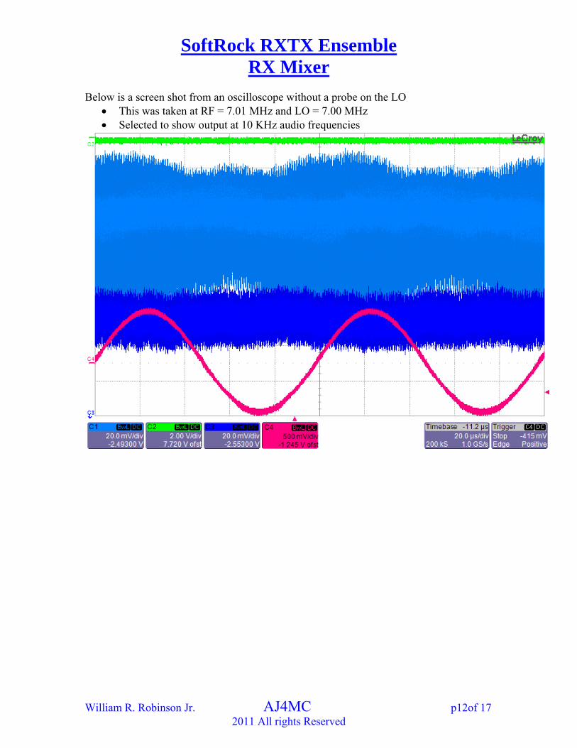
Below is a screen shot from an oscilloscope without a probe on the LO This was taken at RF = 7.01 MHz and LO = 7.00 MHz Selected to show output at 10 KHz audio frequencies

SoftRock RXTX Ensemble RX Mixer
William R. Robinson Jr. AJ4MC p13of 17 2011 All rights Reserved
Below is a screen shot from an oscilloscope without a probe on the LO This was taken at RF = 7.01 MHz and LO = 7.00 MHz Selected to show output at RF frequencies
Below is a screen shot from an oscilloscope with the a probe on the LO This was taken at RF = 7.01 MHz and LO = 7.00 MHz From top to bottom
LO at U10-2 o Not connected but know to be at About 5 Vp-p
RF at U10-3 o About 20 mVp-p o Note noise on RF is greatly decreased if scope if LO is disabled
IF at U10-7 o About 3mVp-p (at desired output)
To small to measure but working backwards from known RX_Opamp gain
o About 70 mVp-p (at Rf frequencies) (with scope probe on LO is removed Rx opamp out at JP2
o About 1.5 Vp-p at 10 KHz (from audio frequency view above)

SoftRock RXTX Ensemble RX Mixer
William R. Robinson Jr. AJ4MC p14of 17 2011 All rights Reserved
Frequency (audio bandwidth)
RXTX ENSEMBLE RX MIXER FREQUENCY RESPONSE
-6
-5
-4
-3
-2
-1
0
1
1 10 100 1000
Frequency Difference RF - LO
dB
V
RF - LO Frequency Difference kHz
The amplitude of the Audio signal at the IF, especially when compared to the
amplitude of the RF energy at the IF, is to small to allow accurate measurments
o Increaseing the RF amplitude beyond what saturates the RC_Opams did not help
o Not saturating and using the output of the RX_Opamps also did not works as the OPamp bandwidth is lower than the IF bandwidth However this yielded a bandwidth of at least 137 kHz
Attempted to use scope FFT but LO signal is to small compared to the RF background noise
Conversion -
Conversion loss = ) log( 20Vrf
Vif
Conversion loss = - )20
3 log( 20
mV
mV
SoftRock RXTX Ensemble RX Mixer
William R. Robinson Jr. AJ4MC p15of 17 2011 All rights Reserved
Conversion loss = 16.48 dBV Isolation
Note time domain clearly shows the isolation of importance is from the LO to the IF
Isolation = )__
log( 20Vrf
ifatVrf
Isolation = )5
70 log( 20
pVp
pmVp
Isolation = -37.08 dBV

SoftRock RXTX Ensemble RX Mixer
William R. Robinson Jr. AJ4MC p16of 17 2011 All rights Reserved
Comparison The table below compares the results
o Conversion loss is greater than expected o Isolation is less than expected
Both are in the opposite direction of what is desired The small magnitudes make the results acceptable in my mide
Real-Measured Simulation CalculatedFrequency (Audio Bandwidth) KHz N/A 336 338Conversion Loss dBV 16.48 13.97 N/AIsolation (LO to IF) dBV 37.08 40.91 N/A

SoftRock RXTX Ensemble RX Mixer
William R. Robinson Jr. AJ4MC p17of 17 2011 All rights Reserved
References
1. Robson, Richard R. Sr., WB5RVZ, Ensemble RXTX Project, http://www.wb5rvz.com/sdr/ensemble/index.htm, online, accessed 2011.
2. Goodman, Pete, G1FGQ, Fist of Fourier, PartI-IVt, http://garage-shoppe.com/wordpress/, online, accessed 2011.
3. Tayloe, Dan, N7VE, Ultra Low Noise, High Performance, Zero IF Quadrature Product Detector and Preamplifier, http://www.norcalqrp.org/files/Tayloe_mixer_x3a.pdf, online, accessed 2011.
4. http://www.wolframalpha.com/input/?i=solve++x%2B2%2B%28x*35%29%2F%28x%2B35%29+%3D+50%2F4, online, accessed 2011.
5. Mini-Circuits, Modern Mixer Terms Defined, http://www.minicircuits.com/pages/pdfs/mixer1-4.pdf, online, accessed 2011.
6. Horowitz, Paul and Hill, Winfield, The Art Of Electronics Second Edition, (Cambridge University Press 1989) Section 1.19 RC Filters, p36-37
7. Bowick, Chris, RF Circuit Design 2nd Edition (Elsevier Inc 2008), p63. 8. Robinson, William AJ4MC, Maximum Power Transfer (another of these short
papers). http://bellsouthpwp2.net/w/r/wrobinson/ , online, accessed 2011. 9. Robinson, William AJ4MC, SoftRock RXTX Ensemble Antenna Low Pass
Filter (another of these short papers). http://bellsouthpwp2.net/w/r/wrobinson/, online, accessed 2011.