Embed Size (px)
Citation preview

SOFTbank E-Book Center Tehran, Phone: 66403879,66493070 For Educational Use.

Manual of Ready-MixedConcrete
J.D.DEWARDirector
British Ready Mixed Concrete Associationand
R.ANDERSONProduct Officer
British Aggregate Construction Materials Industries
BLACKIE ACADEMIC & PROFESSIONALAn Imprint of Chapman & Hall
London · Glasgow · New York · Tokyo · Melbourne · Madras
© 1992 Taylor & Francis Group, LLC SOFTbank E-Book Center Tehran, Phone: 66403879,66493070 For Educational Use.

Published by Blackie Academic & Professional, an imprint of Chapman & Hall,Wester Cleddens Road, Bishopbriggs, Glasgow G64 2NZ, UK
Chapman & Hall, 2–6 Boundary Row, London SE1 8HN, UK
Blackie Academic & Professional, Wester Cleddens Road, Bishopbriggs,Glasgow G64 2NZ, UK
Van Nostrand Reinhold Inc., 115 Fifth Avenue, New York NY10003, USA
Chapman & Hall Japan, Thomson Publishing Japan, Hirakawacho NemotoBuilding, 6F, 1–7–11 Hirakawa-cho, Chiyoda-ku, Tokyo 102, Japan
DA Book (Aust.) Pty Ltd, 648 Whitehorse Road, Mitcham 3132, Victoria,Australia
Chapman & Hall India, R.Seshadri, 32 Second Main Road, CIT East, Madras600 035, India
This edition published in the Taylor & Francis e-Library, 2004.
First edition 1988Second edition 1992
© 1992 Chapman & Hall
ISBN 0-203-48775-3 Master e-book ISBN
ISBN 0-203-79599-7 (Adobe eReader Format)ISBN 0 7514 0079 3 (Print Edition) 0 442 30866 3
Apart from any fair dealing for the purposes of research or private study,or criticism or review, as permitted under the UK Copyright Designs andPatents Act, 1988, this publication may not be reproduced, stored, ortransmitted, in any form or by any means, without the prior permissionin writing of the publishers, or in the case of reprographic reproductiononly in accordance with the terms of the licences issued by the CopyrightLicensing Agency in the UK, or in accordance with the terms of licencesissued by the appropriate Reproduction Rights Organization outside theUK. Enquiries concerning reproduction outside the terms stated hereshould be sent to the publishers at the Glasgow address printed on thispage.
The publisher makes no representation, express or implied, with regardto the accuracy of the information contained in this book and cannotaccept any legal responsibility or liability for any errors or omissions thatmay be made.
A catalogue record for this book is available from the British Library Library of Congress Cataloging-in-Publication data available
© 1992 Taylor & Francis Group, LLC SOFTbank E-Book Center Tehran, Phone: 66403879,66493070 For Educational Use.

Preface
The first edition of this manual was warmly received as a straightforward andwell-written guide to the technology and practice of the ready-mixed concreteindustry. The industry is constantly changing, not only by a self-driven desireto improve standards and quality, but also in response to the changing needsof the marketplace, and the requirements to adapt to new and revised codes ofpractice.
The manual has been completely updated to take account of changes inBritish Standards—in particular those relating to concrete specification andtesting, and to cements. A particularly important inclusion is the concept of theDesignated Mix, which has been welcomed by the construction industry atlarge as a major improvement to the way of specifying concrete for particularend-uses. Throughout, we have also taken the opportunity to amend and addto the text where we have perceived a need to present information and ideasdifferently. As a result this revised edition is an improvement on the firstedition and should serve the needs of the market equally well.
We have retained the overall structure and format of the successful firstedition and, as before, to enable clear and logical presentation of theinformation, the book is divided into two main sections: Part 1, Technology,and Part 2, Practice. The Technology section provides the background to thetechnical aspects of materials, concrete, control and testing, with the Practicesection dealing with methods of concrete production, specification,construction, and quality assurance.
As before, the book is aimed at a wide readership within the constructionindustry. It is equally relevant to the contracts manager, the site engineer, thebuyer working with a contractor, and will be of considerable value to theconsulting engineer, the architect and the quantity surveyor. It will be aninvaluable handbook for materials suppliers and testhouses and for all whosupply plant, equipment or materials, or who make, sell test or use ready-mixed concrete. Lecturers and researchers in universities and colleges willfind it a useful source of reference.
JDDRA
© 1992 Taylor & Francis Group, LLC SOFTbank E-Book Center Tehran, Phone: 66403879,66493070 For Educational Use.

Acknowledgements
The authors gratefully acknowledge that many of the principles and methods describedare the distillation of years of experience generated by the many individuals whocollectively make up the ready-mixed concrete industry, its suppliers and its clients.The net result may be taken as a summation of views for which the authors areprivileged to be the selectors and arbiters. Naturally, the authors take responsibility forexpressing the views and the facts and for any omissions or errors.
To minimize the risk of error, Mr B.V.Brown, Senior Technical Executive of ReadyMixed Concrete (United Kingdom) Ltd, kindly read and commented upon the wholeof Part 1, and the authors are particularly grateful to him. On two specializedsubjects—cements and admixtures—thanks are due for expert comments from MrG.F.Masson, National Technical Manager, Blue Circle Industries plc, and Dr P.C.Hewlett, Managing Director, Cementation Research Ltd and visiting professor at theUniversity of Dundee. For providing particular help with recent developments we wishto thank Mr P.M.Barber (QSRMC) and Dr T.A.Harrison (BCA).
The comments and criticism of Mr P.E.D.Howes of ARC Ltd at the drafting stagewere much appreciated by both the authors, and material provided by Mr P.Male, thenof Steetley Quarry Products, Mr D.Bickley, then of Pioneer Concrete (UK) Ltd., andMr P.N.Staples of Tilcon Ltd., provided the basis for much of Part 2.
The following published papers have been used by permission of their authors andpublishers in suitably modified, updated or abbreviated forms: ‘BRMCA Guide:Concrete Mixes, an Introduction to the BRMCA Method of Mix Design’, and‘BRMCA Guide: BRMCA Concrete Control System’ (BRMCA); ‘Monitoring concreteby the CUSUM system’ (B.V.Brown and the Concrete Society); ‘Ready MixedConcrete Mix Design’ (Municipal Engineer); Testing Concrete for Durability(Palladian Publications); ‘Quality Scheme for Ready Mixed Concrete TechnicalRegulations’ (QRSMC); ‘The workability of ready-mixed concrete’ (RILEM).
A number of tables and figures have been adapted from published papers asacknowledged in the references. Particular thanks are due to the following forpermission to reproduce data, tables or figures: Mr F.W.Beaufait; Mr B.V.Brown;Professor R.K.Dhir; Dr A.M.Neville; Mr K.Newman; Mr B.Osbaeck; ProfessorS.Popovics; Mr R.Ryle; Mr R.E.Spears; ACI; BACMI; BRMCA; BSI; BCA; ConcreteInternational; The Concrete Society; Controller of HM Stationery Office; ERMCO;Municipal Engineer; New Civil Engineer; Palladian Publications; Pitman Books Ltd;Pergamon Press Ltd; RILEM; RMC Technical Services Ltd.
Extracts from BS 6089:1981 are reproduced by permission of BSI. Completecopies can be obtained from them at Linford Wood, Milton Keynes MK 14 6LE.
Thanks are given to Mr Robert Phillipson, Director General of BACMI, forpermitting the text to be transferred to a BACMI word processor which has made theediting and re-editing of drafts a far simpler task than it would have been otherwise.We also thank the publishers for their support.
© 1992 Taylor & Francis Group, LLC SOFTbank E-Book Center Tehran, Phone: 66403879,66493070 For Educational Use.
Contents
PART 1: TECHNOLOGY OF READY-MIXED CONCRETE
Introduction: History of ready-mixed concrete
1 Materials for concrete 1.1 Aggregates
1.1.1 Maximum aggregate size 1.1.2 Grading 1.1.3 Silt, clay and fine dust 1.1.4 Shape and texture 1.1.5 Water absorption 1.1.6 Relative density 1.1.7 Bulk density, void content and voids ratio 1.1.8 Moisture content 1.1.9 Chloride content 1.1.10 Deleterious materials 1.1.11 Shells 1.1.12 Uniformity 1.1.13 Non-standard aggregates 1.1.14 Making the best use of natural resources 1.1.15 Moisture movement 1.1.16 Lightweight aggregates 1.1.17 Heavyweight aggregates
1.2 Cementitious materials 1.2.1 Grading, mean size and fineness 1.2.2 Relative density 1.2.3 Water demand 1.2.4 Setting times 1.2.5 Strength at 28 days 1.2.6 Ratio of early to 28-day strength 1.2.7 Sulphate resistance 1.2.8 Alkali content 1.2.9 Chloride content 1.2.10 Colour 1.2.11 Ground granulated blastfurnace slag and pulverized-fuel ash
1.3 Admixtures 1.3.1 Accelerators 1.3.2 Retarders 1.3.3 Water-reducers (normal and superplasticizers) 1.3.4 Air entrainment 1.3.5 Superplasticizers 1.3.6 Pigments 1.3.7 Foaming agents
1.4 Other materials 1.4.1 Pfa to BS 3892: Part 2, Grade A 1.4.2 Silica fume (micro-silica) 1.4.3 Fibres
1.5 Water for concrete
© 1992 Taylor & Francis Group, LLC SOFTbank E-Book Center Tehran, Phone: 66403879,66493070 For Educational Use.

2 Properties of fresh concrete 2.1 Uniformity and stability 2.2 Workability
2.2.1 Workability test methods 2.3 Pumpability 2.4 Water demand and water/cement ratio 2.5 Rate of change of workability 2.6 Influence of transporting on the workability of ready-mixed concrete
2.6.1 Cement content 2.6.2 Aggregate grinding 2.6.3 Water content and initial workability 2.6.4 Admixtures 2.6.5 Ambient conditions 2.6.6 Bulk volume of concrete 2.6.7 Transporting method
2.7 Effects of transporting of concrete on strength and workability 2.8 Limitations on delivery time 2.9 Retempering of concrete 2.10 Laboratory simulation of ready-mixed concrete
3 Properties of hardened concrete 3.1 Surface quality 3.2 Cracking of concrete 3.3 Strength
3.3.1 Strength development with age 3.4 Durability
3.4.1 Concrete mobility 3.4.2 Covercrete and heartcrete 3.4.3 A background to specifying durability 3.4.4 Corrosion of reinforcement 3.4.5 Chlorides in concrete 3.4.6 Alkali-silica reaction
4 Mix design 4.1 Principles of mix design 4.2 BRMCA method of concrete mix design
4.2.1 Use of base data from BRMCA mix design method 4.2.2 Example: selecting batch proportions for specified design
mix requirements 4.2.3 Selection of batch proportions for a prescribed mix 4.2.4 Example: selecting batch proportions for a standard mix 4.2.5 The predictable future 4.2.6 Technical advice on concrete properties based on the BRMCA
method 4.3 Mix design using ggbs or pfa
4.3.1 Example: an adjustment to a mix design for the use of pfa 4.4 Judging concrete mix design 4.5 Water/cement ratio—free or total 4.6 Meeting durability requirements
4.6.1 Equivalent strength grades—ensuring durability
5 Statistics for quality control, mix design and compliance 5.1 Statistical terms 5.2 Variation 5.3 Distribution 5.4 Normal distribution
© 1992 Taylor & Francis Group, LLC SOFTbank E-Book Center Tehran, Phone: 66403879,66493070 For Educational Use.

5.5 Calculations of mean, standard deviation and other parameters 5.6 Sources of variation 5.7 Influence of mean strength level on standard deviation 5.8 Standard deviation due to sampling and testing 5.9 Relevance of standard deviation for concrete mix design 5.10 Statistical implication of compliance rules
5.10.1 Current compliance rules of BS 5328 5.10.2 Influence on producer’s risk of faults in sampling and testing for
compliance
6 Quality control 6.1 Forward control 6.2 Immediate control 6.3 Retrospective control 6.4 Quality monitoring 6.5 The cusum system of strength monitoring
6.5.1 Principles 6.5.2 Control of mean strength 6.5.3 Monitoring of standard deviation 6.5.4 Significance of trends 6.5.5 Design of masks 6.5.6 Advantages over other systems 6.5.7 Cusum for correlation of predicted and actual strength 6.5.8 Example: cusum in operation 6.5.9 Plotting cusum charts 6.5.10 Action following changes 6.5.11 Investigation of the cause of a change 6.5.12 Computerization
6.6 BRMCA concrete control system 6.6.1 Initial situation 6.6.2 Test data 6.6.3 Prediction of 28-day strength 6.6.4 Mean strength control (by counting rule) 6.6.5 Standard deviation 6.6.6 Early-28-day strength relationships
7 Sampling and testing ready-mixed concrete 7.1 Sampling ready-mixed concrete 7.2 Effects of non-standard testing on strength 7.3 Simple checks on validity of results 7.4 Communication 7.5 Simple visual checks on the crushed cube 7.6 NAMAS register of test houses 7.7 Interpreting test results for strength
7.7.1 Apparent compliance failures 7.7.2 Checking on validity 7.7.3 Action relating to valid compliance failures 7.7.4 Establishing strength of concrete in the structure 7.7.5 Interpretation of in-situ cube strength 7.7.6 Use of non-destructive testing 7.7.7 Remedial work 7.7.8 Increasing the strength and durability of concrete in the structure
7.8 Checking mix proportions or quantities 7.8.1 Analysis of fresh concrete 7.8.2 Chemical analysis of hardened concrete
7.9 Checking the quantity of concrete 7.9.1 Measuring construction volume
© 1992 Taylor & Francis Group, LLC SOFTbank E-Book Center Tehran, Phone: 66403879,66493070 For Educational Use.

7.9.2 Measuring volume to be concreted 7.9.3 Measuring volume of plastic concrete after finishing 7.9.4 Measuring volume of hardened concrete
7.10 Variation in density and yield
PART 2: PRACTICE
8 Production, delivery and quality assurance 8.1 Production methods
8.1.1 Material types 8.1.2 Storage capacity 8.1.3 Processing sequence 8.1.4 Truckmixer capacity and throughput 8.1.5 Planning requirements 8.1.6 Quality control requirements 8.1.7 Regulatory requirements 8.1.8 Duration of operations 8.1.9 Health and safety
8.2 Organizing production and delivery 8.3 Delivery
8.3.1 Truckmixers 8.3.2 Tippers 8.3.3 Conveyors
8.4 Quality assurance
9 Specifications and supervision 9.1 Interpreting specifications
9.1.1 Uses of concrete specifications 9.2 Specifying and supervising the supply of ready-mixed concrete
9.2.1 Specification clauses 9.2.2 Checking 9.2.3 Designated mixes
10 Ready-mixed concrete on site 10.1 Choosing ready-mixed concrete
10.1.1 Site mixing costs 10.1.2 Ready-mixed v. site mixing supply 10.1.3 Ready-mixed concrete plants on site
10.2 Site preparations for ready-mixed concrete 10.2.1 Site/supply liaison 10.2.2 Setting up a concrete supply 10.2.3 Programming concrete deliveries
10.3 Ready-mixed concrete on site 10.3.1 Delivery ticket 10.3.2 Addition of water at site 10.3.3 Safety 10.3.4 Delays 10.3.5 Placing the concrete 10.3.6 Compacting the concrete 10.3.7 Curing the concrete
10.4 Pumping concrete 10.4.1 The contractor 10.4.2 The pump hirer 10.4.3 The ready-mixed concrete supplier
© 1992 Taylor & Francis Group, LLC SOFTbank E-Book Center Tehran, Phone: 66403879,66493070 For Educational Use.
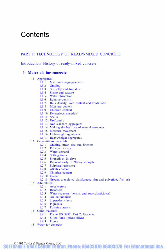
11 Organizations 11.1 BRMCA 11.2 BACMI 11.3 QSRMC
11.3.1 Technical standards 11.3.2 Order processing 11.3.3 Technical records 11.3.4 Plant and production 11.3.5 Continuing surveillance and enforcement 11.3.6 NACCB accreditation
11.4 NACCB 11.5 NAMAS
Appendix 1: QSRMC technical regulations
Appendix 2: Conversion factors
Appendix 3: Designated mixes in accordance with BS 5328:Part 2 Section 5
References
References to standards
© 1992 Taylor & Francis Group, LLC SOFTbank E-Book Center Tehran, Phone: 66403879,66493070 For Educational Use.

Abbreviations
A/C Aggregate/cement ratioASR Alkali-silica reactionBACMI British Aggregate Construction Materials IndustriesBCA British Cement AssociationBD Bulk densityBRE Building Research EstablishmentBRMCA British Ready Mixed Concrete AssociationBS British StandardBSI British Standards InstitutionC Characteristic compressive strength, as in grade C40C&CA The Cement and Concrete Association (now British Cement
Association)CEGB Central Electricity Generating BoardCMF Cement Makers’ Federation (now British Cement Association)CP Code of PracticeCSTR Concrete Society Technical ReportCTMA Construction Testing Manufacturers Associationggbs Ground granulated blastfurnace slagkg Kilogramkg/m3 Kilograms per cubic metrekm Kilometrelasrpc Low alkali sulphate-resisting Portland cementmm MillimetreNACCB National Accreditation Council for Certification BodiesNAMAS National Measurement Accreditation ServiceN/mm2 Newtons per square millimetrepc Portland cementpfa Pulverized-fuel ashQA Quality AssuranceQC Quality ControlQSRMC Quality Scheme for Ready Mixed ConcreteRD Relative densitys.d. Standard deviationsrpc Sulphate-resisting Portland cementSSD Saturated and surface dryTMS Target mean strengthW/C Water/cement ratio
© 1992 Taylor & Francis Group, LLC SOFTbank E-Book Center Tehran, Phone: 66403879,66493070 For Educational Use.

Part 1TECHNOLOGY
© 1992 Taylor & Francis Group, LLC SOFTbank E-Book Center Tehran, Phone: 66403879,66493070 For Educational Use.

Photograph courtesy RMC (UK) Ltd.
© 1992 Taylor & Francis Group, LLC SOFTbank E-Book Center Tehran, Phone: 66403879,66493070 For Educational Use.

Introduction: History of ready-mixedconcrete
The history of concrete in Britain [1, 2, 3] dates back to Roman times, but itwas not until the 1930s that concrete was supplied ready-mixed in the UK.The constituent materials come from the earth in bulk, so concrete is mosteconomically produced by handling the materials in bulk and mixing them inbulk. It was the advantages of scale and efficiency of mechanical mixing, plusimproved control resulting from weighing the ingredients, that opened the wayfor the supply of concrete ready-mixed.
Ready-mixed concrete was patented in Germany in 1903, but the means oftransporting it had not developed sufficiently well to enable the concept to beexploited. There were significant developments in the USA in the first quarterof the 20th century: the first delivery of ready-mixed concrete was made inBaltimore in 1913, and the transit-mixer was born in 1926.
In the UK it was not until 1930 that a Dane, K.O.Ammentorp [1], who hadbeen involved in starting ready-mixed concrete in Copenhagen, emigrated toEngland, and in 1931 erected a plant at Bedfont, west of London, near whatwas to be eventually the site of Heathrow Airport. He suffered from planningdelays, even in those days! The company, Ready Mixed Concrete Ltd,operated the plant housing a 2 cu yd central mixer, supplying six 1¾ cu ydcapacity agitators (Fig. I.1), with an output of 40 cu yd/h. Aggregates werecontained in a four-compartment bin of about 100 cu yd capacity. The cementwas man-handled in bags.
At about the same time, the British Steel Piling Company became interestedin transit-mixers and imported two from the USA. These had a mixingcapacity of about 5 cu yd and were filled (with difficulty!) through a smallhole in the back.
The next company to start was the Scientific Controlled Concrete Co Ltdof Staines, in 1934. They used Jaeger truckmixers, produced under licence byRansome & Rapier Ltd. It appears that this firm operated for only a short time;some of their equipment was taken over by Truck Mixed Concrete(Southampton) Ltd and used in the Winchester Bypass. Next came JaegerSystem Concrete Ltd, Glasgow, which much later was taken over by TilconLtd. In 1936 the Express Supply Concrete Ltd was founded as a subsidiary ofBalfour Beatty Ltd. It had two plants, the first at Paddington and the secondat Alperton, with a total of 30 Jaeger truckmixers. At these plants the cementwas delivered in metal 5-ton capacity bulk containers, which were lifted off
© 1992 Taylor & Francis Group, LLC SOFTbank E-Book Center Tehran, Phone: 66403879,66493070 For Educational Use.

MANUAL OF READY-MIXED CONCRETE4
the delivery lorries and emptied into bins by opening a gate at the bottom ofthe container. A pump was then used to elevate the cement from the groundbins to the bins over the cement weighing floor; a similar system is used forhandling large plastic bags of bulk cement in some locations today. Anotherearly producer from the aggregate side of the business was Trent Gravel Ltd,whose first plant was erected at Attenborough, near Nottingham, in 1939. Atthe outbreak of World War II in 1939, there were only six firms producingready-mixed concrete in England and Scotland, one supplying concrete inagitators from a central mixer and the others using the truckmixer system.
Figure I.1 Early towerplant with truckmixers and agitator. Courtesy of Tilcon Ltd
© 1992 Taylor & Francis Group, LLC SOFTbank E-Book Center Tehran, Phone: 66403879,66493070 For Educational Use.

INTRODUCTION 5
The handling of materials in bulk has dominated the design of ready-mixedconcrete plants from the start. They were aligned initially to quarry practice,using drag-line excavators for aggregates and bucket elevators for cement.Long, high conveyors were used to elevate the aggregates to a height thatallowed them to be stored above the weigh-scales and to be gravity-fed asrequired, from storage bin to weigh-hopper, from weigh-hopper to mixer andfrom mixer to the delivery vehicle. These tower plants (Fig. I.2) came intovogue in the late 1930s and after World War II. Some of them saw wartimeservice on airfield construction and other projects requiring large volumes ofconcrete. Tall plants were more acceptable in quarries and gravel pits but, withthe requirement to provide plants nearer the markets for the concrete, plantdesigners had to provide units that were more environmentally acceptable.
The development of chevron conveyor belts meant that steeper anglescould be used in elevating the aggregates, thus requiring less space.Separating the storage and weighing of aggregates from the storage andweighing of the cement meant that the height of plants could be considerablyreduced. The split-level plants introduced in the late 1960s are still populartoday and now dominate the industry, but the demands of planning authoritiesfor lower-profile plants have led to the production of some even morecompact plants. With compactness, plant transportability became viable, andnow some ready-mixed concrete producers provide plants on majorconstruction projects.
Ready-mixed concrete is a service as well as a product, and deliverytechniques have developed along with the production side. In the 1930s,
Figure I.2 Conical agitator (1950s). Courtesy of C & CA and RMC Ltd
© 1992 Taylor & Francis Group, LLC SOFTbank E-Book Center Tehran, Phone: 66403879,66493070 For Educational Use.

MANUAL OF READY-MIXED CONCRETE6
conical agitators and Jaeger truckmixers did yeoman service, although theywere susceptible to the rear door opening in transit, resulting in prematuredischarge. Their use continued into the early 1950s, and as late as 1985 a siteforeman in Central Scotland rang up the shipping office to ask for ‘a Jaegerof concrete’! The industry has generally encouraged the collection of concretefrom its central mixer plants. Normal haulage lorries were frequent callers inthe early days, then came tippers. Some companies operated telehoist tippersfor a while, but it was the rotating drum mixer which prevailed and developedinto the modern truckmixer which has really made the supply of ready-mixedconcrete commercially viable.
The current shape of truckmixer drum, relying on reversible action forloading and mixing then contra-rotating for discharging, developed into thelate 1950s, so that by the 1980s the most common size, based on a three-axlechassis, mixes and transports six cubic metres of concrete. Larger units(carrying nearly 9 m3) and smaller ones (down to 2.5 m3) are in use, but theindustry has accepted the 6 m3 truckmixer as the basic fleet unit.
The ready-mixed concrete industry has tended to outpace the constructionindustry in its willingness to innovate. Not all new ideas survived commercialpressures, mainly because purchasers were not always willing to pay apremium for an improvement in quality or service. Wet hoppers were suppliedto sites into which the truckmixers could quickly discharge the concrete,allowing the contractor to collect and place the concrete at his own pace. Siteconveyors were tried, and there are a few truckmixers operating withconveyors mounted on them. The early versions were heavy, resulting in aconsiderable reduction in the volume of concrete that could be carried in thedrum. Developments using aluminium to lighten the conveyor have revivedtheir popularity.
Figure I.3 Ready-mixed concrete in Britain. Courtesy of BRMCA and BACMI
© 1992 Taylor & Francis Group, LLC SOFTbank E-Book Center Tehran, Phone: 66403879,66493070 For Educational Use.

INTRODUCTION 7
There are even truckmixers with concrete pumps mounted on the chassis,but although such innovation is appreciated abroad, it has not gained favourin the UK. The ready-mixed concrete industry entered the concrete pumpingbusiness with enthusiasm, but lack of response from customers meant that thepumps were eventually sold off to a few concrete pumping specialists. InBritain, the percentage of ready-mixed concrete that is pumped is markedlylower than in the rest of Europe.
Cement weighing recorders were in vogue in the late 1960s, but the electro-mechanical gear did not stand up well to the dust-laden atmosphere, and 20years had to elapse before solid-state electronics arrived to allow themanufacture of reliable processing, batching and recording equipment ateconomic prices. The processing systems have evolved from lever-arms, toservo-systems using compressed air, hydraulics and electronics, to computersand micro-processors, each step aimed at giving improved control of thewhole production process.
The acceptance and growth of the ready-mixed concrete industry betweenthe 1950s and 1974 was quite remarkable, with 31 million cubic metres peryear being produced at the peak. The downturn in the construction industrywas naturally reflected in the concrete production figures, and a period ofrationalization and consolidation followed (Fig. I.3).
The short history of the ready-mixed industry has been dominated by theneed to produce and deliver a high-quality product economically. The fact thatmost in-situ concrete is now supplied ready-mixed is a measure of howsuccessful the industry has been, in terms of quality, service, and price to thecustomer.
Seeking to provide assurance of the quality of ready-mixed concrete hasalways been a requirement of the industry and was first manifested in theBRMCA Authorization Scheme, launched in 1968. This scheme introducedand enforced standards ensuring that each registered plant was able to produceconcrete of the requisite quality and quantity. An additional section was addedto the scheme in 1972, providing a very early approach to QA, by introducingauditing and certification of quality control procedures. In 1982, whenBACMI was formed, it introduced a code of practice based on BS 5750quality systems.
The Quality Scheme for Ready Mixed Concrete (QSRMC) was establishedin 1984 and was granted the ninth certificate accredited by the NACCB.With its independent Governing Board regulations based on BS 5750: Part1—Quality systems, BS 5328—Concrete and NAMAS regulations forlaboratory performance, the scheme epitomizes the current philosophy ofthird party QA.
The cost to the industry of providing ever-increasing levels of qualityassurance has been considerable, while the complexity of mixes beingspecified has increased further the costs of quality control. The fact that mostin-situ concrete is now supplied ready-mixed is a measure of how successfulthe industry has been in terms of demands for quality, service, and price.
© 1992 Taylor & Francis Group, LLC SOFTbank E-Book Center Tehran, Phone: 66403879,66493070 For Educational Use.

1 Materials for concrete
Ready-mixed concrete is a composite material which, like all well-designedcomposites, has resultant properties that combine the best qualities of thecomponent materials.
As the number of components is increased, so the range of properties anduses are increased, with greater opportunity for optimization and economicbenefit. Fig. 1.1 illustrates the benefits obtained in reducing water content asthe number of solid components is increased from one for cement paste, to twofor mortar to three for concrete.
Typical concrete consists of only 4–6 components:
Portland cementSandCoarse aggregate (one, two or three fractions)Water.
The options and number of components can be increased by adopting variouscombinations of the following:
Different types of Portland cementGgbs or pfa
Figure 1.1 Influence of the number of solid components on the water demand of Portlandcement-based composites. Redrawn and adapted from Dewar [12]
© 1992 Taylor & Francis Group, LLC SOFTbank E-Book Center Tehran, Phone: 66403879,66493070 For Educational Use.

Natural sand, crushed rock fines or fine lightweight or heavyweightaggregateDifferent maximum sizes of natural gravel, crushed rock or blastfurnaceslag as coarse aggregatesLight- or heavyweight coarse aggregatesAdmixtures.
The opportunities for optimization do not end with the choice of materials.There is also considerable scope for selection of proportions appropriate tospecification requirements and the intended uses of the concrete.
1.1 Aggregates
Aggregates have two prime functions in concrete:
(i) Providing concrete with a rigid skeletal structure(ii) Reducing the void space to be filled by the cement paste.
By selecting different sizes and stypes of aggregates and different ratios ofaggregate to cement, a wide range of concretes can be produced economicallyto suit different requirements.
Important properties of an aggregate which affect compliance with BritishStandards and affect the performance of ready-mixed concrete are [13]:
Nominal maximum sizeGrading and mean sizeSilt, clay or fine dust contentShape and surface textureWater absorptionRelative densityBulk densityMoisture content.
Other properties which have particular importance for some aggregates or forsome special uses are:
Chloride contentSusceptibility to alkali-silica reactionDeleterious materials contentMoisture movement.
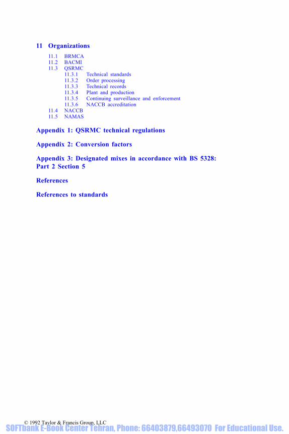
For use generally as an aggregate, materials need to be essentially chemicallyinert and physically strong and stable. Most natural rocks, whether massive orbroken down by nature into gravel and sand, make first-class concretingaggregates [5]. The rock types in most common use are flint, quartzite,limestone, gritstone, granite and basalt. A more complete list is shown inTable 1.1.
© 1992 Taylor & Francis Group, LLC SOFTbank E-Book Center Tehran, Phone: 66403879,66493070 For Educational Use.
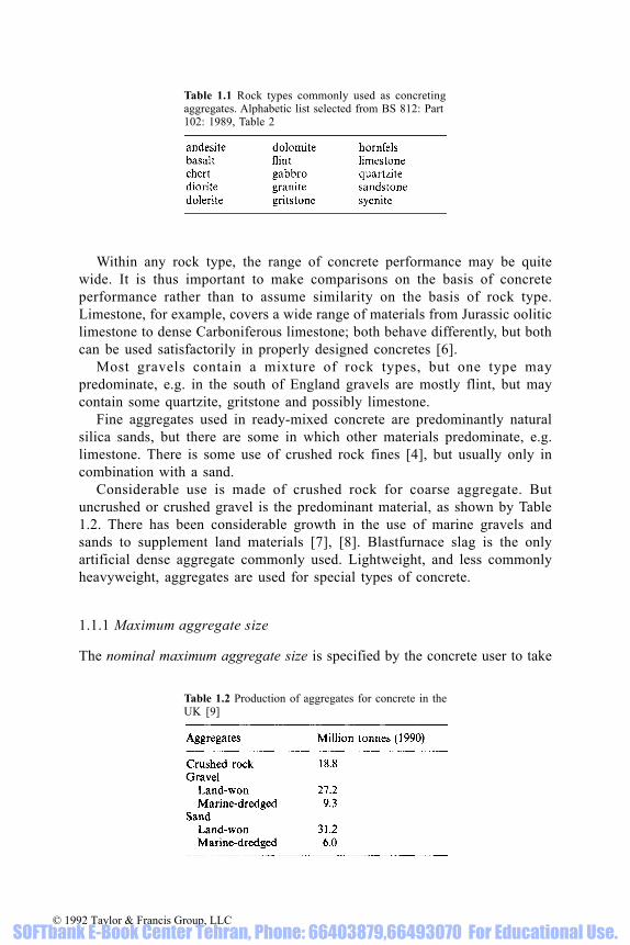
Within any rock type, the range of concrete performance may be quitewide. It is thus important to make comparisons on the basis of concreteperformance rather than to assume similarity on the basis of rock type.Limestone, for example, covers a wide range of materials from Jurassic ooliticlimestone to dense Carboniferous limestone; both behave differently, but bothcan be used satisfactorily in properly designed concretes [6].
Most gravels contain a mixture of rock types, but one type maypredominate, e.g. in the south of England gravels are mostly flint, but maycontain some quartzite, gritstone and possibly limestone.
Fine aggregates used in ready-mixed concrete are predominantly naturalsilica sands, but there are some in which other materials predominate, e.g.limestone. There is some use of crushed rock fines [4], but usually only incombination with a sand.
Considerable use is made of crushed rock for coarse aggregate. Butuncrushed or crushed gravel is the predominant material, as shown by Table1.2. There has been considerable growth in the use of marine gravels andsands to supplement land materials [7], [8]. Blastfurnace slag is the onlyartificial dense aggregate commonly used. Lightweight, and less commonlyheavyweight, aggregates are used for special types of concrete.
1.1.1 Maximum aggregate size
The nominal maximum aggregate size is specified by the concrete user to take
Table 1.1 Rock types commonly used as concretingaggregates. Alphabetic list selected from BS 812: Part102: 1989, Table 2
Table 1.2 Production of aggregates for concrete in theUK [9]
© 1992 Taylor & Francis Group, LLC SOFTbank E-Book Center Tehran, Phone: 66403879,66493070 For Educational Use.
construction. A small proportion of oversize and undersize material is permittedin order not to unduly restrict the way in which aggregate is screened during itsproduction. The normal maximum sizes are 40 mm, 20 mm and 10 mm. Use ofa larger maximum size extends the range of sizes of particles in concrete andpermits lower fine aggregate content and lower water content.
1.1.2 Grading
The distribution of the sizes of aggregate particles is called the grading.Grading is usually described in terms of the cumulative percentage by mass ofaggregate passing particular sieves, the commonest of which have apertureswhich are approximately twice the size of the next sieve below in the series:
50 mm37.52010
52.361.180.6 (600 microns)0.3 (300 microns)0.15 (150 microns)
For historic reasons, the 5 mm sieve has become the size separating coarsefrom fine aggregate, although some small fraction of a coarse aggregate ispermitted to pass 5 mm and some fine aggregate is permitted to be coarserthan 5 mm.
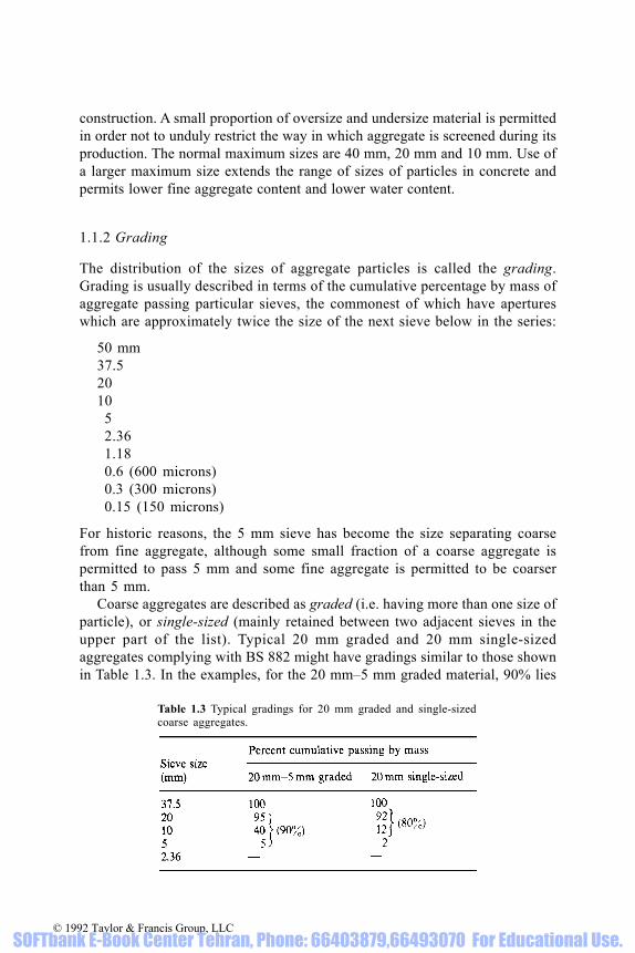
Coarse aggregates are described as graded (i.e. having more than one size ofparticle), or single-sized (mainly retained between two adjacent sieves in theupper part of the list). Typical 20 mm graded and 20 mm single-sizedaggregates complying with BS 882 might have gradings similar to those shownin Table 1.3. In the examples, for the 20 mm–5 mm graded material, 90% lies
Table 1.3 Typical gradings for 20 mm graded and single-sizedcoarse aggregates.
© 1992 Taylor & Francis Group, LLC SOFTbank E-Book Center Tehran, Phone: 66403879,66493070 For Educational Use.

between the two sizes used to describe it and, for the 20 mm single-sizedmaterial, 80% lies between the sieve used to describe it and the next size below.These gradings are merely examples; different values will be obtained for othersources and they may vary with time and from consignment to consignment.
For compliance with BS 882, the standard for concreting aggregates, thepermitted ranges for the two materials are as shown in Table 1.4.
Fine aggregates complying with BS882 are now divided into threecategories (coarse, medium and fine), whereas until recently there were fourcategories (zones 1, 2, 3 and 4). A typical medium grading might be as shownin Table 1.5. Table 1.5 Typical medium grading of fine ag-
gregate to BS 882.
Table 1.6 Comparison of new and obsolete fine aggregate gradinglimits of BS 882.
Table 1.4 BS 882 limits for 20 mm graded and single-sized coarseaggregates.
© 1992 Taylor & Francis Group, LLC SOFTbank E-Book Center Tehran, Phone: 66403879,66493070 For Educational Use.

A comparison is given in Table 1.6 of the ranges permitted by BS 882 forA comparison is given in Table 1.6 of the ranges permitted by BS 882 forthe percentage passing the 600-micron sieve for the new and obsolete systemsof fine aggregate grading classification. The new system permits more sandsto be accepted which have been found satisfactory for use in concrete. Fineaggregates in each of these grading categories can be used for making highquality concrete; however, a sand at the coarse end of category C is usuallyless likely to be suitable for concretes of low cement content and therefore lesssuitable for general purpose concreting. Some very fine sands, e.g. 90%retained between 300- and 150-micron sieves, which are too fine for the Fcategory of BS 882, can be used to produce excellent concrete [10, 11], whichunderlines the still arbitrary nature of current classification.
An all-in aggregate is an aggregate already blended for use in concrete,containing coarse and fine aggregate either processed as one material orreconstituted by blending of separately processed materials. All-in aggregateis normally permitted only for less critical concrete construction.
The overall grading of the total aggregate is either a continuous or a gapgrading. A continuous grading implies some proportion between each sievewhereas a gap grading will be missing intermediate material. A gap in theoverall aggregate grading commonly occurs when fine sands are used. Bothgap and continuous gradings are equally satisfactory for use in concrete.
Gradings of aggregates are often shown as grading curves or charts. Fig.1.2 shows gradings for single-sized 20 and 10 mm coarse aggregates, and fora medium sand together with the overall grading for the three aggregatescombined in the proportions 40/20/40. The bottom scale for sieve size is alogarithmic scale, the scale distance between adjacent sizes beingapproximately equal. The same materials are detailed in Table 1.7 togetherwith the proportioning to show how the overall grading can be calculated. The
Figure 1.2 Examples of gradings of aggregates
© 1992 Taylor & Francis Group, LLC SOFTbank E-Book Center Tehran, Phone: 66403879,66493070 For Educational Use.

Table 1.7 Example of individual and combined gradings.
*% of material×% passing/100**Sum of previous three columns.
© 1992 Taylor & Francis Group, LLC SOFTbank E-Book Center Tehran, Phone: 66403879,66493070 For Educational Use.
difference between adjacent percentages in the final column is the percentagematerial between the corresponding sieves, e.g. 22% lies between the 10 and5 mm sieves. It will be apparent from the final column in the table and theresultant curve in Fig. 1.2 that the overall aggregate grading is continuous, notgapped.
Gradings of fine and coarse aggregates are important properties ofaggregates for concrete because of their influence on packing, and thusvoidage, which will in turn influence the water demand and cement content ofconcrete [12]. There are no recognized ideal gradings for aggregates in theUnited Kingdom. Uniformity of grading within and between consignments isvital [13]. Knowledge of the current grading of an aggregate is important, sothat allowance can be made for the effects of any changes. There are rareinstances of types of construction or finish which may require specialrestrictions of grading, e.g. some road-paving finishing operations achievebetter results when 10 mm aggregate is omitted; some exposed aggregatefinishes may require omission of 10 mm aggregate or the use of fine sand forarchitectural reasons.
The proportion of fine to coarse aggregate is selected to suit the materials,their proportioning and the type and use of concrete. This is considered furtherunder mix design (Chapter 4).
1.1.2.1 Mean size. There is no standard way of estimating mean size of agraded material. One simple way [12] is to estimate, from the grading, thesieve size at which 50% of material is retained or passed. In the case of thegradings in Table 1.7, the 20 mm, 10 mm and fine aggregates have mean sizesof about 15 mm, 7 mm and 0.6 mm.
A small mean size for the fine aggregate relative to that of the coarseaggregate is important to minimize particle interference, which will affectwater demand and workability of concrete adversely. On the other hand, themean size of the fine aggregate must not be so small that it results ininterference with cement grains.
1.1.3 Silt, clay and fine dust
The finest particles in fine aggregate are essential constituents needed tosupplement cement to reduce the void content, particularly in lean concretes.
They fulfil a vital function by providing cohesion, in aiding the pumpabilityof concrete and in reducing the tendency for water to bleed from concrete. Itis important that over-emphasis on cleanliness of aggregates does not lead toa loss of these vital ingredients. In the case of marine aggregates, it is ofparticular importance to ensure that loss of fine material is minimized duringdredging.
However, too much fine material, particularly in concretes of high cementcontent, is less desirable. BS 882 places a maximum limit of 3% for silt andclay content of all natural sands, irrespective of use, where silt and clay are
© 1992 Taylor & Francis Group, LLC SOFTbank E-Book Center Tehran, Phone: 66403879,66493070 For Educational Use.

defined as material passing a 75-micron sieve. Similarly, a corresponding limitof 1% is placed on silt, clay or fine dust content of coarse aggregate.
It is stressed that these limits are arbitrary and the case can be made forhigher limits in specific cases [14]. Indeed, lean mixes can tolerate andactually need a higher proportion of silt or dust to assist cohesion. Cement isa very 1expensive substitute for silt!
Crushed rock fines have a higher void content than natural sand of a similargrading, and therefore need a higher content of material passing the 75-micronsieve, which is one reason why BS 882 allows up to 15% fine dust comparedwith only 3% for silt and clay in sands for general-purpose concreting.
Fine dust or clay coating could adversely affect bond with cement paste. Itis sometimes observed that oven-dried aggregates prepared in the laboratoryfor testing are dulled by the presence of silt, clay or dust. This should not beconsidered detrimental unless it is excessive, because fine particles insuspension in water will naturally appear as coating when the aggregate hasbeen dried. Clay lumps of significant size and number are obviously unwanted.
The proportion of certain swelling clay minerals such as montmorillonite,in sands, may need to be reduced to avoid high water demands and excessivemoisture movement of concrete [5], [15].
The common field settling test for clay and silt by settlement of sand in asaline solution in a measuring cylinder is a very simple and useful test, but ismisleading because the fine material settles in a very loosely packed layer ontop of the coarser particles. As much as 10%, or even more, of silt measuredby bulk volume in this test may not represent much more than 3% whenmeasured by weight. Because of this, BS 882 permits up to 10% in the volumetest before it is necessary to perform the more tedious but precise test byweight.
1.1.4 Shape and texture
Shape and texture of aggregates are affected by the nature and geologicalhistory of the materials and by the aggregate production process, moreespecially the degree and method of crushing.
Generally, round and smooth particles, particularly in fine aggregate, willaid workability of concrete and lead to a lower voidage and lower waterdemand and, incidentally, to less plant wear. Angular and rough particles ofcoarse aggregate will bond better to cement paste and often lead to higherstrengths in mixes of high cement content.
A proportion of flaky material can be tolerated by adjustment of theproportion of fine to coarse aggregate to reduce void content, but whenexcessive or variable may produce difficulties in pumping, placing,compacting and finishing.
To minimize placing problems, it is important for aggregate producers to
© 1992 Taylor & Francis Group, LLC SOFTbank E-Book Center Tehran, Phone: 66403879,66493070 For Educational Use.

control the crushing process to minimize variation in shape betweenconsignments of aggregates.
1.1.5 Water absorption
The water absorption of an aggregate is related to its particle porosity. Typicalvalues of water absorption for natural aggregate lie in the range 0.5–5% bymass. The porosity can be calculated as relative density (OD)×absorptionpercent. For example, if the relative density (OD) is 2.50 and the waterabsorption is 3%, the porosity is 2.50×3=7.5% by volume.
Water absorbed into aggregate particles contributes to their mass but takesno part in providing concrete with workability and is not part of the voidageof the cement paste. Thus, absorbed water does not reduce strength by itspresence. Indeed it may be beneficial as a reservoir of moisture to assist laterhydration of cement. A limit on aggregate absorption is difficult to justify andis only rarely specified.
1.1.6 Relative density
Relative density (specific gravity) of an aggregate can be best understood asthe ratio of the mass per cubic metre of the aggregate (W) to the mass of thesame volume of water (V) (1000 kg/m3). There are three relative densities ofaggregate, illustrated in Table 1.8, which may be used in concrete calculations.Of these, relative density on a Saturated and Surface Dried basis is possiblythe most relevant but its measurement is less precise than Apparent RelativeDensity. Apparent relative density is always the highest of the three, andrelative density on an oven-dried basis is always the lowest. If the water
Table 1.8 Relative densities of aggregates. W, mass per m3 of aggregate; V, mass of samevolume of water; abs, water absorption
© 1992 Taylor & Francis Group, LLC SOFTbank E-Book Center Tehran, Phone: 66403879,66493070 For Educational Use.
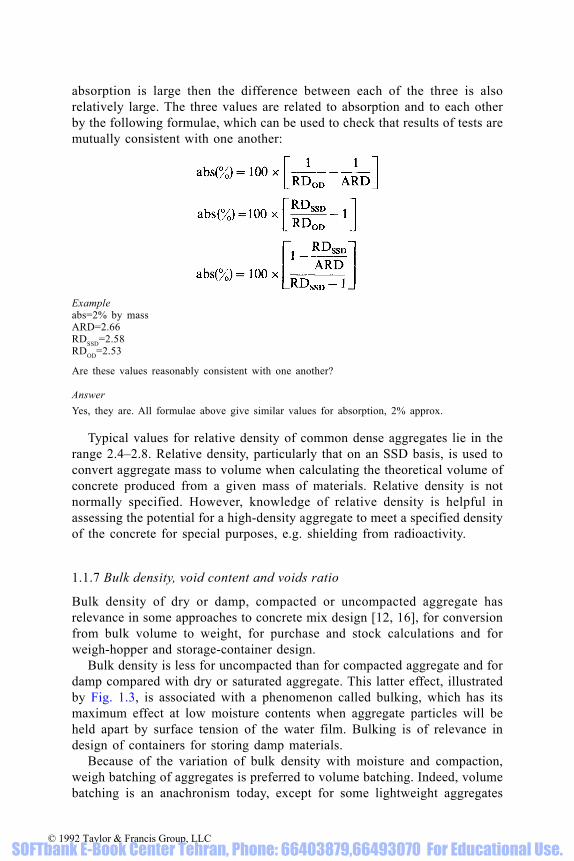
absorption is large then the difference between each of the three is alsorelatively large. The three values are related to absorption and to each otherby the following formulae, which can be used to check that results of tests aremutually consistent with one another:
Exampleabs=2% by massARD=2.66RDSSD=2.58RDOD=2.53
Are these values reasonably consistent with one another? AnswerYes, they are. All formulae above give similar values for absorption, 2% approx.
Typical values for relative density of common dense aggregates lie in therange 2.4–2.8. Relative density, particularly that on an SSD basis, is used toconvert aggregate mass to volume when calculating the theoretical volume ofconcrete produced from a given mass of materials. Relative density is notnormally specified. However, knowledge of relative density is helpful inassessing the potential for a high-density aggregate to meet a specified densityof the concrete for special purposes, e.g. shielding from radioactivity.
1.1.7 Bulk density, void content and voids ratio
Bulk density of dry or damp, compacted or uncompacted aggregate hasrelevance in some approaches to concrete mix design [12, 16], for conversionfrom bulk volume to weight, for purchase and stock calculations and forweigh-hopper and storage-container design.
Bulk density is less for uncompacted than for compacted aggregate and fordamp compared with dry or saturated aggregate. This latter effect, illustratedby Fig. 1.3, is associated with a phenomenon called bulking, which has itsmaximum effect at low moisture contents when aggregate particles will beheld apart by surface tension of the water film. Bulking is of relevance indesign of containers for storing damp materials.
Because of the variation of bulk density with moisture and compaction,weigh batching of aggregates is preferred to volume batching. Indeed, volumebatching is an anachronism today, except for some lightweight aggregates
© 1992 Taylor & Francis Group, LLC SOFTbank E-Book Center Tehran, Phone: 66403879,66493070 For Educational Use.

having low particle densities and high water absorptions, which may bebatched more accurately by bulk volume.
For dry normal-weight aggregates, bulk density can vary from 1000–2000kg/m3 dependent on grading, shape, surface texture and degree of effort incompaction. An uncrushed gravel will normally have a higher loose bulkdensity than a crushed rock aggregate of the same grading, but the differencewill be smaller for the compacted than the uncompacted state.
Bulk densities of different aggregates cannot be compared usefully withouttaking account of the densities of the materials of which each is composed.Void content measurement is a way of overcoming this problem. The voidcontent can be assessed from the bulk density and relative density as follows:
or
For example, if the OD bulk density of a coarse aggregate is 1500 kg/m3
and the OD relative density is 2.50, then the voids content is
Void content is the percentage of voids, discounting particle pores, in the total
volume of aggregate. Values for different aggregates of a similar grading can becompared directly. For the same grading, materials of lower void content can beexpected to require a lower water content in concrete. When the gradings differ,comparisons cannot be made directly, and complex analysis (or, more usually,concrete trial mixes) is necessary to compare materials.
At low compactive effort, lower void contents are associated with a wide
Figure 1.3 Bulking factor for sands with different moisture contents. After Neville [130]
© 1992 Taylor & Francis Group, LLC SOFTbank E-Book Center Tehran, Phone: 66403879,66493070 For Educational Use.

range of particle size and with round smooth particles. This implies thataggregate of large maximum size and rounded natural gravels and sands tendto have lower water demands in concrete than crushed rocks, crushed rockfines, flaky aggregates and small maximum size aggregates of any type.
In one approach to mix design [12, 16], the term ‘voids ratio’ is used; thisis defined as the ratio of voids to the volume of solid material and can becalculated from bulk density and relative density as follows:
For example, using the same data as in the previous example,
Void content and voids ratio are related to each other as follows:
1.1.8 Moisture content
Moisture content is a function of the natural state and the processing ofaggregates. Gravels and sands, whether dredged or excavated dry, usually needto be washed to remove unwanted excess silt and clay, and are usually storedfor a time in the open, when they may collect rain water or drain, dependingon weather conditions. Typical moisture contents for gravels and sands lie inthe ranges 1–5% and 5–15% respectively. Crushed rock aggregates arenormally processed dry, but may contain some moisture, particularly whenstored in stockpiles.
Moisture content is of interest because of its contribution to the mass ofdamp aggregate and also to the water content of concrete. Knowledge ofmoisture content is important when purchasing aggregate by weight and whenbatching aggregate for concrete.
Moisture will drain through aggregates, and there will almost always be amoisture gradient through stockpiles and storage bins. Sampling of aggregatesfor moisture content needs to be thoroughly representative or related tospecific bulk quantities if meaningful results are to be obtained.
Moisture content measurement can be based on free or total moisture, thedifference being the absorbed water:
Free moisture Total moisture Aggregatecontent (%) = content (%) - water absorption (%)by mass by mass by mass
© 1992 Taylor & Francis Group, LLC SOFTbank E-Book Center Tehran, Phone: 66403879,66493070 For Educational Use.

1.1.9 Chloride content
Chloride content of concrete may sometimes be restricted by specifications inrespect of resistance to sulphate attack or steel corrosion, e.g. by BS 8110, asshown in Table 3.2 in section 3.4.5 on concrete durability.
BS 882 provides values, shown in Table 1.9, which may be adopted by thespecifier who wishes to include chloride limits for the aggregate, but these, areoptional, not obligatory.
Chloride is a naturally-occurring ion in sea water and in some landaggregates. Marine-dredged aggregates can be expected to contain somechloride, but this is usually significantly reduced [7, 8], compared with seawater, by washing the aggregates with estuarine, river or mains water, asshown by Fig. 1.4, and may be further reduced by draining.
Other salts in sea water are not generally considered harmful to concrete[17]. However, the presence of sodium may need to be taken into account for
Figure 1.4 Relation between chloride content of aggregates, moisture content and sea-watercontent of wash water
Table 1.9 Optional maximum chloride content limits provided in BS 882
© 1992 Taylor & Francis Group, LLC SOFTbank E-Book Center Tehran, Phone: 66403879,66493070 For Educational Use.
alkali-silica reaction. For convenience, chloride measurements may be used toestimate reactive sodium oxide levels in aggregates.
1.1.10 Deleterious materials
There are some materials [18, 19] which may be considered deleterious inconcreting aggregates, for example lignite and coal; however, small proportionsof such materials can usually be tolerated. Indeed, where such inclusions occur itis very unlikely that an aggregate could be provided totally free of them becauseof the technical difficulties and cost of ensuring complete removal.
Tolerance is justifiable on the grounds that such residual material usuallyhas only a slight weakening effect which is overcome by use of more cementin designed mixes. In some parts of the country, free mica for example maybe present in quantity; this may provide delight to one architect who isattracted by the sparkle but concern to others who are aware of its platy shape.Again, competent mix design will ensure that any increase in water demand,loss of cohesion, and loss in strength are adequately compensated by a slightincrease in cement and fine aggregate contents and there need be little concernover its presence [20, 21].
Obviously there will be cases where the specifier is particularly concernedover surface appearance or durability and may wish to use materials which arepractically free from deleterious materials. It is important that the specifier makesclear his special needs at an early stage and understands that this may requireimporting of special materials from other areas, with consequent increased costs.
Possibly one of the most difficult materials to remove is iron pyrites, anatural material occurring in some parts of the country, which can decay on thesurface of concrete to form unsightly brown rust stains.
Mine tailings need to be checked before use as a concrete aggregate. In theSW of England, the use of Killas (Devonian slate or shale) containing clay andMundic (iron pyrites) has led to deleterious expansion of precast concreteblocks.
Some types of silica can react slowly with alkalis from cements to form anexpansive gel which, under extreme conditions, might eventually disruptconcrete. As yet, an accepted BS test is not available for assessing thesusceptibility of an aggregate to reaction with alkalis.
Certain rock types are recognized as being unlikely to react, either becausethey are silica-free or because any contained silica is unlikely to be in a reactiveform [22, 145]. These are shown in Table 1.10. This list is, however, of limitedvalue because the vast majority of sands contain silica in a range of forms. It willalso be noted that two of the commonest coarse aggregates, flint (or chert) andquartzite, are not included in the list. Fortunately, it is now becoming acceptedthat where the total aggregate consists of 60% or more flint or chert, it can betreated as unreactive. Generally, the few cases of serious damage which haveoccurred have been restricted to the Midlands and the SW of England. Furtherinformation is provided in the cements section (Section 1.2.8).
© 1992 Taylor & Francis Group, LLC SOFTbank E-Book Center Tehran, Phone: 66403879,66493070 For Educational Use.

1.1.11 Shells
Shell is often considered erroneously as a deleterious material. Most shells areformed of calcium carbonate, the substance of limestone, having a similarrelative density of about 2.70, which is higher than that of flint (2.65), andhaving a lower absorption. Broken and ground shell in sand is almost alwayssmooth and polished, aiding workability. Its flat or slightly curved shape maybe a slight disadvantage but is compensated for by its smoothness. Some landaggregates as well as marine aggregates contain shell, and such materialsusually perform at least as well as aggregates without shell.
In the case of coarse aggregates, there may be some concern over hollowshells or large flaky shells [23]. In the case of hollow shells, cement pasteusually enters and fills the voids [24]. In the case of large flaky shells, theirpresence is usually compensated for by a much more rounded shape of theremaining aggregate particles, so that no significant fears should remainconcerning their use [7, 8, 24].
BS 882 includes limits on shell as follows: maximum 8% in the fractioncoarser than 10 mm; maximum 20% in the 10 mm–5 mm fraction; no limit forfine aggregate. Although the limits are not technically necessary, they are notusually found to be too restrictive.
1.1.12 Uniformity
The most important features of aggregate for the ready-mixed concreteproducer are uniformity within consignments and consistency over time, ratherthan the absolute value of any property, provided of course the values are incompliance with specifications [13, 25]. When an important property alterssignificantly, it is vital for the ready-mixed concrete producer either to beinformed or to identify it for himself to minimize the risk of operating outsidea specification requirement for the concrete.
The most important properties of aggregates affecting the properties offresh concrete are:
Table 1.10 Aggregates categorized by the Concrete Society as unreactive withalkalis [22]
Note: Opaline silica must be absent
© 1992 Taylor & Francis Group, LLC SOFTbank E-Book Center Tehran, Phone: 66403879,66493070 For Educational Use.

Moisture content of fine aggregateGrading of fine and coarse aggregateVoid contents of fine and coarse aggregate.
Moisture is critical because of its influence on the amount of water requiredto be added to concrete to produce the desired workability. Grading of fineaggregate is important because of its influence on the cohesiveness ofconcrete. Void contents of fine and coarse aggregate are important because oftheir influence on both cohesiveness and water demand of concrete. Voidcontents are influenced particularly by changes in grading and shape, both ofwhich can be influenced, in the case of gravels and sands, by the extent towhich oversize material is being crushed and the uniformity with which it isbeing blended with the uncrushed material.
1.1.13 Non-standard aggregates
It is difficult to write one standard for use of aggregates in concretenationwide which provides safeguards for all potential users but at the sametime does not place restrictions on experienced and knowledgeable concretespecifiers, contractors and ready-mixed concrete producers. To overcome this,BS 5328 and BS 8110 permit aggregates to be used which do not comply fullywith aggregate standards, where there is agreement between the purchaser andsupplier of concrete. This basis of such an agreement might be the evidenceof satisfactory use in practice or the availability of appropriate test data, aspermitted by BS 8110.
1.1.14 Making the best use of natural resources
The fewer unnecessary restrictions placed by specifiers upon aggregates, themore economic and effective use can be made of locally available materials.
1.1.15 Moisture movement
When concrete dries out or is wetted again, the cement paste attempts toshrink or expand. Usually this movement is adequately restrained by theskeletal aggregate structure. Indeed, this is an important function of theaggregate.
Most concreting aggregates have very low moisture movements, but certaintypes of aggregate, notably the more absorptive types of dolerite, havephysical pore structures which are particularly susceptible to movement withchanging moisture condition [26].
Moisture movement test methods have relatively poor reproducibility, andthis should be taken into account when appraising test results. There is nowa BS method, BS 812: Part 120, for testing and classifying drying shrinkageof aggregates in concrete.
© 1992 Taylor & Francis Group, LLC SOFTbank E-Book Center Tehran, Phone: 66403879,66493070 For Educational Use.

Using this test method, drying shrinkages for flint, quartzite, limestone andgranite concretes are typically in the range 0.01–0.04%, whereas values ofover 0.07% can be obtained with some aggregates. BS 812: Part 120 and BREDigest 357 [26] recommend that aggregates with drying shrinkage valuesabove 0.075% should be limited in their use generally to situations wherecomplete drying out never occurs or for structural members that aresymmetrically and heavily reinforced and not exposed to the weather.
1.1.16 Lightweight aggregates
The commonest available types of lightweight aggregate for use in ready-mixed concrete are sintered pulverized fuel ash and expanded clay, but thefollowing have also been used: expanded slate or shale, expanded or pelletizedslag, natural pumice, exfoliated vermiculite, and expanded perlite.
Some materials are available as normal-sized coarse aggregates, but somemay be available only in the smaller single sizes. Some coarse materials haverounded shape and smooth texture whereas others, particularly those crushedfrom clinker, are angular, rough and vesicular. Some materials are available asfine aggregate, usually obtained by crushing of coarse particles, so that theshape and texture of the fine aggregate are likely to be angular, rough andvesicular.
Particle densities can be very low, sometimes below unity, which means thatparticles can float on water, causing problems during mixing andtransportation [27]. Segregation can be reduced by including an air-entrainingagent in the concrete which can have the additional benefit of further loweringdensity [27].
Aggregate particles are often highly absorptive and may be readily friable,abradable or degradable. Water absorption values can approach or evenexceed 100%, implying that particles can absorb more water than their owndry weight.
The range of possible densities and applications of lightweight aggregateconcretes [28, 29] (Table 1.11) can be widened by suitable selection from thefollowing techniques, separately or in combination:
No finesLow workability, partial compactionNormal workability, full compactionHigh or low cement contentLightweight or normal-density fine aggregateAir entrainment.
In producing ready-mixed lightweight aggregate concrete, the following needto be considered.
© 1992 Taylor & Francis Group, LLC SOFTbank E-Book Center Tehran, Phone: 66403879,66493070 For Educational Use.

(i) Very light and dry particles can blow off stockpiles and belt conveyors(ii) Stockpiles and bin contents may need heavy hosing and draining to
ensure stable moisture content(iii) Additional ground storage or overhead bins may be needed. Movement
of aggregate may require additional measures, e.g. normal vibration maynot allow flow from hoppers
(iv) Accurate batching is difficult unless uniform and known moisturecontent is obtained—volume batching may be appropriate for very lightmaterials
(v) Mixing method may need modification—a longer mixing time may benecessary
(vi) Fast and excessive loss of workability can occur due to absorption bydry aggregates or to degrading of particles
(vii) Plastic and hardened density and yield are more variable than for denseaggregate concrete
(viii) Trucks cannot be loaded to full weight capacity(ix) Staff need time and training to become accustomed to unusual materials
or mixes.
1.1.17 Heavyweight aggregates
The commonest available types of heavyweight coarse aggregates [30] arebarytes (barium sulphate), ilmenite and magnetite (iron ores), and steel shot,although other varieties of iron ores and shots are sometimes used. High-density concrete is often required for shielding from radioactivity in medicalor nuclear constructions. Using the above materials as coarse aggregates withnatural sands, the densities shown in Table 1.12 might be achieved [30].
The following aspects need to be taken into account in producing high-density concrete.
(i) Special attention is needed to control workability and to minimizesegregation and bleeding with heavy coarse aggregate.
Table 1.11 A range of lightweight concrete densities and strengths [28, 29]
© 1992 Taylor & Francis Group, LLC SOFTbank E-Book Center Tehran, Phone: 66403879,66493070 For Educational Use.

(ii) Reduced volumetric capacity of storage bins, weighbatchers, conveyors,mixers and transporting vehicles for a given weight. Additional groundand bin storage may be needed.
(iii) There is a possible need for higher-capacity balances for weighing testspecimens, particularly for plastic density.
(iv) Heavy coarse and fine aggregates may not be available with normal BS882 gradings. In some instances, only coarse aggregate may beavailable.
(v) Batch weights of materials will need adjusting to take account of higherdensity of coarse aggregate and the capacity of the equipment.
(vi) Some aggregates may degrade during mixing.
Water reducing agents may assist segregation problems and marginallyincrease density.
1.2 Cementitious materials
Cementitious materials, or hydraulic binders, are obviously key components ofconcrete. In fresh concrete, they are the finest particles and they have thefunction of providing workability, cohesion and stability. In the hardenedconcrete they have responsibility for providing mechanical strength, arelatively impermeable pore structure and an internal environment to resistchemical attack of the concrete and to protect any steel reinforcement.
In order to achieve these benefits, the various complex components of theCementitious materials react with water at various rates in concrete and formnew products. This process, termed hydration, results in an interwovenphysically bonded material structure, the components and porosity of whichare dependent upon the types and activities of the Cementitious materials, theamount of water (originally present), the internal moisture and temperaturehistory and the age of the concrete. Some of the components react relativelyquickly, while others take many years to complete their reactions, and indeedmay never be permitted to achieve anywhere near their full potential becauseof the absence of a suitable stable internal environment.
The chemical reactions create heat, which in turn promotes increased rates
Table 1.12 Examples of concrete densities ob-tained with heavy coarse aggregate [30]
Note: Higher densities are achievable if heavy fineaggregate is also used. s
© 1992 Taylor & Francis Group, LLC SOFTbank E-Book Center Tehran, Phone: 66403879,66493070 For Educational Use.

of reaction, so that the process of stiffening and hardening is initially anaccelerating one. To ensure that loss of workability is small during the firstfew hours, the main reactions are delayed by inclusion of a form of calciumsulphate in the Portland cement component. One benefit of the heatdevelopment and accelerating process is that a significant proportion ofconcrete’s potential strength may be achieved in the heart of the concretewithin a few days of construction. One disadvantage of the otherwise slowprocess of hydration is that unless the correct internal environment ismaintained throughout, for a long time—many weeks or months—the keysurface zone for durability may achieve only a fraction of its potential strengthand impermeability.
The properties of cementitious materials which have the greatest relevancefor the ready-mixed concrete producer are:
Grading, mean size and finenessRelative densityWater demandSetting timesStrength in concrete at 28 daysRatio of 7- to 28-day concrete strength.
Other properties which have particular relevance for meeting certainspecification requirements are sulphate resistance, alkali content, chloridecontent and colour.
The commonest cementitious materials in use in ready-mixed concrete are:
Portland cement (pc)Sulphate-resisting Portland cement (srpc)Portland blastfurnace cementPortland pulverized-fuel ash cement
Ground granulated blastfurnace slag (ggbs) in combinationwithPulverized-fuel ash (pfa) Portland cement.
1.2.1 Grading, mean size and fineness
A typical grading for Portland cement might be as shown in Table 1.13. The meansize is about 0.015 mm (15 microns), compared with about 0.5 mm for a sand and 10mm for a graded 20 mm gravel, so that there is an appreciable size differential betweenthe three major solid components of concrete. This size differential minimizes particleinterference and enables the sand to fill the voids in the gravel and the cement to fillthe voids in the sand, leaving just the voids in the cement to be filled by water and air.
The fineness of cement is measured as a surface area per unit mass whichbears some relation to mean size, as well as to grading, particle shape and
© 1992 Taylor & Francis Group, LLC SOFTbank E-Book Center Tehran, Phone: 66403879,66493070 For Educational Use.

texture. A typical range of values for fineness of Portland cement is 290–390m2/kg [32].
For ready-mixed concrete, the cement grading or fineness has a significantinfluence on water demand, cohesiveness, bleeding, surface finish and rate ofgain of strength. Finer cements tend to have higher water demands in richermixes, but have increased cohesiveness, reduced bleeding, enable a moreuniform surface finish to be achieved and produce higher earlier strengths. Infact, a rapid-hardening Portland cement is usually just a more finely-groundPortland cement. Ggbs and pfa have gradings of a generally similar order tothose of Portland cement.
1.2.2 Relative density
Typical relative densities for cementitious materials (pc, sulphate-resistingcement, ground granulated blastfurnace slag and pulverized-fuel ash) areshown in Table 1.14.
1.2.3 Water demand
The water demand of concrete [12, 16] can be related to the cement particlesize distribution and to the water demand of cement paste. This latter propertyis measured by a test for standard consistency using the Vicat apparatus. Thistest involves determining the water content producing a certain plungerpenetration in a small sample of freshly compacted paste.
In effect, the standard consistence test is a bulk density test like that foraggregates, except the medium is not air but water, which is obviously
Table 1.13 Typical grading of cement [31]
Table 1.14 Typical relative densitiesfor cementitious materials
© 1992 Taylor & Francis Group, LLC SOFTbank E-Book Center Tehran, Phone: 66403879,66493070 For Educational Use.

appropriate because that is the medium in which cement is required to operatein concrete.
A typical range of values for water content in the Vicat test is 24–28% bymass, i.e. water/cement of 0.24–0.28. This means a voids content of about 0.5(or a voids ratio near unity) which, considering the wide gradings of cement,is rather high and suggests rather angular or irregular-shaped particles, whichis confirmed by photomicrographs. The voidage is also higher due to someagglomeration of cement particles.
In the case of ggbs, similar or slightly lower water demands and voidcontents are usually obtained, while for pfa, appreciably lower values occur,associated with the round, smooth shape of pfa particles. These help to explainwhy concretes containing pfa (and to a lesser extent ggbs) can show markedlylower water demands and also greater cohesion.
When using cements of a given type having high water demands, highercement contents will be required in designed mixes, for a given workabilityand strength.
1.2.4 Setting times
The historic terms set or setting are very misleading, suggesting that thereexists a time, or times, when cement paste or concrete suddenly developsdifferent characteristics. In fact, the so-called initial and final sets are merelytwo arbitrary points in time on the continuous curve of stiffening at whichparticular needles, used in the Vicat test for cement paste, penetrate the pasteto particular extents. This is shown diagrammatically in Fig. 1.5.
Figure 1.5 Illustration of the arbitrary nature of initial set and final set of Portland cement paste
© 1992 Taylor & Francis Group, LLC SOFTbank E-Book Center Tehran, Phone: 66403879,66493070 For Educational Use.

Setting times serve a useful purpose in enabling the performance of twocements to be compared, as in Fig. 1.6. Thus, by comparison of setting times,cement 1 is seen to be a faster-stiffening cement than cement 2, and this mayhave significance for concrete, particularly with the richer mixes.
It does not necessarily follow that fast-stiffening cements have higherearlier strengths, although the assumption can sometimes be valid. Similarly,it does not necessarily follow that rapid-hardening Portland cements stiffenmore rapidly.
Cements are generally controlled in their manufacture in such a way thatsetting times for cement pastes are typically about 1½–4 h for the so calledinitial set and 3–5 h for the final set [32]. These times cannot be translateddirectly to concrete, as shown in Fig. 1.7, because the rates of stiffening ofconcrete will depend on the water and cement contents. Also, the rates of heatdevelopment and hydration are much greater in neat cement pastes. Forexample, a mix with a cement content of 200 kg/m3 and an initial slump of 100mm might still be workable 5 h after mixing compared with say 2 h for cementpaste. Environmental conditions, particularly temperature, may significantlyaffect the comparison. Cement setting times should therefore be used withcaution, and preferably only for comparison purposes between cements. Onlyinitial setting time is limited in cement standards.
It is an interesting point to contemplate that if hydration is a very longprocess, then at the microscopic or submicroscopic level there are always partsof concrete which are stiffening and hardening. Indeed, some unhydratedcement particles are almost always detectable, even in very old concrete. Thisis, at one and the same time, both heartening and discouraging; heartening
Figure 1.6 The valid use of initial and final setting times to compare rates of stiffening ofdifferent cements
© 1992 Taylor & Francis Group, LLC SOFTbank E-Book Center Tehran, Phone: 66403879,66493070 For Educational Use.

because concrete may always have the capacity for further gain in strength; butdiscouraging in that it is not possible to fully utilize what has been purchased.
Despite the insistence upon the smooth curve of stiffening, there arepossibilities for fast or almost instantaneous stiffening. One of these is ‘flash’set, which can be associated with faults in the cement-making process, but isdifficult to distinguish from other influences. Fortunately, it is rare for UKcements to exhibit this problem. ‘False’ set is slightly more likely, but stillrare, the commonest cause being too high a grinding temperature. If a samplehas been retained, it can be tested for false set using the American test inASTM-C 451 [33]. Both false and flash set are considered again under section2.2 on workability of concrete. When false set occurs, there is a fast buttemporary loss of workability which can be regained if the concrete is remixedor vibrated. The inclusion of ggbs or pfa will usually increase stiffening times.
1.2.5 Strength at 28 days
The strength of cement is obviously an important property for ready-mixedconcrete.
The standard test relates to a mortar prism having a W/C of 0.50. Veryapproximately, concrete of 0.60 W/C will have a strength of 0.8× thestandard mortar strength. Thus, 40 N/mm2 concrete cube strengthcorresponds to a standard mortar prism strength of about 50 N/mm2 at thelower W/C.
Cements are classed in terms of characteristic mortar prism strengths, thecommonest standard values being 32.5, 42.5 and 52.5 N/mm2.
Figure 1.7 Illustration of different rates of stiffening for cement paste and concrete made withthe same cement
© 1992 Taylor & Francis Group, LLC SOFTbank E-Book Center Tehran, Phone: 66403879,66493070 For Educational Use.

The mean strength of a part of the cement consignment used in a batch ofready-mixed concrete, typically about 1.5 or 2 tonnes, can be expected todeviate from the short-term bulk average strength by about ±3–5 N/mm2, sothat it is not surprising that the variation in the strength of cement is obviouslya major factor influencing the uniformity of strength of ready-mixed concrete.
The reporting of bulk average values, over a period of time, provides someextremely valuable information. It enables the ready-mixed concrete producerto confirm observed changes in mean level of concrete strength in his owncontrol system. Even more important, due to the excellent co-operationbetween the cement and ready-mixed concrete industries, it has been possiblefor cement works to predict changes and to give advance warning to ready-mixed concrete producers.
The types of variation which can be experienced are illustrated in Fig. 1.8a–d, and need to be accounted for in concrete producers’ control systems andmix design.
The inclusion of ggbs or pfa may modify the 28-day strength of concrete
Figure 1.8 Different types of quality variation in cement which may be experienced
© 1992 Taylor & Francis Group, LLC SOFTbank E-Book Center Tehran, Phone: 66403879,66493070 For Educational Use.

due to differences in cementing behaviour and due to influence on waterdemand. Effects may vary with proportions, type and sources of materials.However, the inclusion of ggbs or pfa does not usually result in increasedvariability of concrete. Indeed, reduced variability is often claimed.
1.2.6 Ratio of early to 28-day strength
Because of the 28-day delay between making concrete and obtaining astrength test result at the specified age, it is normal for the ready-mixedconcrete producer to make an early age test, usually at 7 days, or anaccelerated test at 1 to 3 days, from which the 28-day strength is predicted.
Typical UK average strengths for pc to BS 12 in concrete at a water/cementratio of 0.60 are as follows:
3d 25 N/mm2
7d 34 N/mm2
28d 44 N/mm2.
The relationship between 7- and 28-day strength of concrete is complex, but canbe characterized through knowledge of the ratio of 7- to 28-day strength in thestandard cement test of concrete. The ratio may vary from 0.5 to 0.85, dependenton cement type, source and production conditions, and thus can be significantlydifferent from the value of 0.67 (2/3) commonly assumed by specifiers.
When the ratio is relatively constant, then accurate predictions can be made.If it changes, then predictions will become inaccurate until the change has beennotified or detected. Naturally, it will be at least 28 days before the first ratioindicating a change can be seen by the ready-mixed concrete producer, so thatprediction of a change and its notification by the cement works is vital. Again,this is being developed within the system of exchange of information betweenthe cement industry and the ready-mixed concrete industry. An appreciation ofthis variation in 7- to 28-day strength ratio is also important for the concreteuser, who may also be predicting 28-day from 7-day strength.
Composite cements or combinations of pc and ggbs or pfa can be expectedto have lower ratios than for pc alone.
1.2.7 Sulphate resistance
BS 5328 provides advice on the use of pc, srpc, composite cements, ggbs andpfa, as summarized in Table 1.15. BRE Digest 363 provides alternative adviceand indicates benefits at higher sulphate concentrations of using compositecements and combinations of pc with ggbs or pfa [44].
1.2.8 Alkali content
The sodium and potassium oxide contents of cement are expressed as a single
© 1992 Taylor & Francis Group, LLC SOFTbank E-Book Center Tehran, Phone: 66403879,66493070 For Educational Use.

Table 1.15 BS 5328 recommendations* for use of various cements or combinations of cements with ggbs or pfa with 20 mm aggregates in concrete subjectto sulphate attack
*See BRE Digest 363 [44] for alternative recommdations
© 1992 Taylor & Francis Group, LLC SOFTbank E-Book Center Tehran, Phone: 66403879,66493070 For Educational Use.

value for equivalent sodium oxide:
%Na2O+(0.658×%K
2O)
and known as the alkali content of cement. This is important because of itsinfluence on the potential for alkali-silica reaction (ASR) between cement andaggregate in concrete. There is no specified BS limit for alkali content ofcements, although maximum values may be declared by cement-makers.
Cements are considered to be unlikely to react harmfully [22] if the alkalicontent is less than 0.6%, provided active alkalis from other sources do notexceed 0.2%. The value of 0.6% cannot be guaranteed for Portland cements,and applies only for certain sources of sulphate-resisting Portland cements.This guarantee needs to be requested specifically at the time of ordering thecement.
An alternative view [22] is that, irrespective of the alkali level in thecement, alkalis are not significantly harmful, provided the alkali content of theconcrete is below 3 kg/m3, with the benefit that cements of high alkali contentcan be accepted if the cement content does not exceed a corresponding value,taking account of variation above the monthly mean value for alkali contentdeclared by the cement makers.
Table 1.16 provides maximum cement contents corresponding to the rangeof alkali levels observed in the UK. The average level in the cement wasreported to be 0.65% in 1985, ranging from 0.4 to 0.9% [34].
The alkali contents of ggbs and pfa are assumed to contribute only partiallyto alkali-silica reaction. Ggbs or pfa in excess of 25% by mass of cement canbe assumed to act as an alkali diluent and is often recommended as a meansof reducing the risks of ASR. Ggbs may also act positively in some specialway to inhibit the reaction, such that the inclusion of 50% or more ggbs isaccepted as a means of avoiding ASR, irrespective of the alkali content of the
Table 1.16 Maximum Portland cement content in concrete at3 kg/m3 maximum alkali level [22]
Note: Values include allowances for variation in monthly meanalkali content of cement and variation in cement content ofconcrete
© 1992 Taylor & Francis Group, LLC SOFTbank E-Book Center Tehran, Phone: 66403879,66493070 For Educational Use.

cement or the concrete [22]. Further guidance is given in section 3.4.6, dealingwith alkali-silica reaction.
1.2.9 Chloride content
Cement may contain up to 0.1% chloride as a minor constituent which needsto be taken into account when a maximum chloride content of concrete isspecified.
1.2.10 Colour
The density or shade of the grey colour of cementitious materials is the mostimportant factor determining the colour of the concrete. There is no standardrequirement for colour or shade of cementitious materials.
Changes in colour of concrete associated with the cementitious materialsmay be observed when:
(i) Sources of cementitious materials are changed(ii) Variations occur in the cementitious materials(iii) Variations occur in the proportions of cementitious components of
composite cements or combinations blended in the concrete mixer. Generally srpc is a darker grey than pc from the same works, but some pccements can be quite dark. Concretes with pfa may be darker, whereas thosewith ggbs are often lighter. Ggbs may produce a characteristic ‘blue’ shade fora short period early in the life of the concrete, compared with a greenish tingefor pc concrete.
1.2.11 Ground granulated blastfurnace slag and pulverized-fuel ash
Reference has been made to certain aspects of ggbs and pfa under the variousproperties of cements to enable direct comparison, but in view of the acceptedand growing use of those materials, it is appropriate for them to receive afuller consideration separately from Portland cements.
It is important to recognize the significant role they can and do have inincreasing the range of composites. In many instances they enhance theconcrete properties, and do more than act as replacement materials-a belittlingand anachronistic view of their role.
Figure 1.9 shows in an idealized form how the use of ggbs in combinationwith Portland cement to BS 12 can result in an enhanced concrete propertybecause of favourable chemical or physical interactions.
It is equally important to recognize that different sources of cement andggbs or pfa will interact differently, such that each combination needs to beassessed separately and monitored continuously. For these reasons care istaken generally in this section to avoid suggesting specific quantitative
© 1992 Taylor & Francis Group, LLC SOFTbank E-Book Center Tehran, Phone: 66403879,66493070 For Educational Use.

benefits. Where numbers are quoted, they are usually those resulting fromconsensus and incorporated into standards and codes.
The use of ggbs and pfa in concrete has increased in the UK in recent yearsand currently continues to do so for a number of significant reasons [35–38],including:
(i) Developments by suppliers of ggbs and pfa(ii) Favourable relative price of ggbs and pfa compared with cement
(iii) Incentives for energy saving on a national basis(iv) Research and development by the Building Research Establishment,
CEGB, the Steel Industry and individual firms(v) Existence of British Standards for cement incorporating ggbs (Portland
blastfurnace cement, BS 146; high slag blastfurnace cement, BS 4246)(vi) Production of Portland blastfurnace cements in Scotland, Northern
Ireland and SW England(vii) Production of Portland pfa cements in UK(viii) Existence of a British standard for pfa, BS 3892.(ix) Benefits of temperature reduction in massive pours; sulphate resistance,
resistance to alkali-silica reaction(x) Cement shortage in some parts of the UK in earlier years
(xi) Agrément Board Certificates for selected ggbs and pfa(xii) Quality assurance schemes developed by the ready-mixed concrete
industry in conjunction with manufacturers of the ggbs and pfa
Figure 1.9 Idealized representation of the enhancement of properties of ggbs-Portland cementcomposites associated with beneficial interactions between the composites. Adapted fromOsbaeck [110]
© 1992 Taylor & Francis Group, LLC SOFTbank E-Book Center Tehran, Phone: 66403879,66493070 For Educational Use.

(xiii) Experience of the ready-mixed concrete industry of ggbs and pfaconcretes
(xiv) Use by major specifiers and contractors on prestigious contracts(xv) Use of ggbs and pfa elsewhere in the world.
Their acceptability has been increased further by
(i) Publication of British Standards BS 6699 for ggbs and BS 6588 and6610 for Portland pfa and pozzolanic cements
(ii) Publication of BS 8110 which makes significant reference to theacceptability of ggbs and pfa
(iii) Publication of an amendment to BS 5328 permitting ggbs and pfacombinations with opc to have parity with composite cements [39].
1.2.11.1 Specific advantages of ggbs and pfa concretes. Composite cement,ggbs or pfa concretes are generally accepted in the UK to have specificadvantages as follows:
(i) Sulphate resistanceBRE Digest 363 [44] advises that blends of ggbs or pfa with Portlandcement can be used in a range of sulphate conditions. An increasedcementitious materials content is required compared with srpc concrete.In some cases blends are permitted where pc by itself is not allowed.(See Table 1.15).
(ii) Alkali-silica reactionUse of 25% or more ggbs or pfa coupled with a restriction on the alkalicontent of concrete, or the use of 50% or more ggbs with a limit of1.1% on the alkali content of the combination of cement and ggbs, isaccepted as providing a high degree of immunity against alkali-silicareaction such that the potential activity of the aggregate can be ignored[22, 145].
(iii) Temperature rise in massive constructionConsiderable benefit has been obtained in major UK construction bysignificantly reducing the early temperature rise of mass concrete byusing ggbs or pfa while maintaining satisfactory strength development[40] and at considerable cost savings, both directly and also indirectlythrough faster construction.
1.2.11.2 Ggbs or pfa in cement or added in concrete? A choice. The limitedavailability of Portland blastfurnace cement or Portland pfa cement, and theneed for versatility in meeting a wide range of needs and specifications, hasmeant that the ready-mixed concrete industry has been more inclined to useggbs or pfa added directly to the concrete at the mixing stage rather thanalready pre-blended in the cement.
The obvious benefits of stocking a Portland blastfurnace cement or a
© 1992 Taylor & Francis Group, LLC SOFTbank E-Book Center Tehran, Phone: 66403879,66493070 For Educational Use.

Portland pfa cement are that the properties are guaranteed by the maker, whoalso undertakes the sampling and testing. Ready-mixed concrete, ggbs and pfaproducers are often quite prepared to accept these responsibilities.
1.2.11.3 British Standards and Codes of Practice relating to the use of ggbs,pfa and composite cements. Table 1.17 provides a comparison of thespecification requirements for various cements and corresponding blends inthe concrete mixer.
BS 5328 for concrete permits ggbs and pfa to BS 3892: Part 1 to be treatedas part of the cement content when the combination meets the requirements forproportions and properties of the appropriate British standard for a compositecement [39]. For many years Codes of Practice, e.g. CP 110 and CP 114, haveaccepted Portland blastfurnace cement as being on a par with Portland cement.
BS 8110 confirms the position of combinations as being on a par with thecorresponding dry-blended or interground composite cement. BS 8110 alsoaccepts cements and combinations to BS 12, 146 and 6588 as having equalitywith each other for normal durability situations, providing the same strengthgrades of concrete are used.
(i) BS 6699 for ground granulated blastfurnace slagThe requirements of BS 6699 include chemical composition, glass countand fineness, all of which are subject to control by the manufacturer. Ofthese, fineness is probably the most important, to ensure reactivity andwater reduction.
(ii) BS 3892 for pulverized-fuel ashBS 3892 has been revised to take into account the experience gainedsince its initial drafting in 1965, including the use of grading on the 45-micron sieve and the requirement of the concrete industry for a standard
Table 1.17 Strength requirements for common classes of cements to BS 12, 146, 4246, 6588 and6610 and for blends of Portland Cement to BS 12 and ggbs or pfa
© 1992 Taylor & Francis Group, LLC SOFTbank E-Book Center Tehran, Phone: 66403879,66493070 For Educational Use.

providing greater control when pfa is to be used as a cementitiousmaterial in structural concrete. Part 1 of BS 3892 covers this use andincludes a water demand requirement and also an optional test forpozzolanic activity. Eventually it is possible that the latter test maybecome obligatory, but there is insufficient experience to allow it to beso, at the present time.
The reasons for the interest in water demand and pozzolanic activity are toensure that (i) the pfa is behaving as a cementitious material and not merelyas a filler, and that (ii) lack of early cementitious action is compensated, atleast partially, by reduction in water demand. BS 3892: Part 2, for general usesof pfa in concrete, adopts the main features of Part 1, but relaxes the loss onignition and grading requirements. This material is intended for such uses asunreinforced precast concrete products, lean concrete and for grouts andmortars. It is not permitted by BS 8110 or BS 5328 to be treated as part ofthe cement content for durability (see also 1.4.1).
1.2.11.4 Quality scheme for ready-mixed concrete-requirements for ggbs andpfa. It is possible, by the rules of the QSRMC [41], to use ggbs or pfa eitheras a cementitious material or solely as an addition with no assumedcontribution as a cementitious material. In the former case, equality of thecombination against a cement standard is required, whereas in the latter casethe ggbs or pfa is assumed to be behaving as an inert material only. Becauseof the wide range of proportions available through the use of the twoblastfurnace cement standards, it is rare for ggbs to be used other than as acementitious material. At present, pfa to BS 3892: Part 1 covers the use as acementitious material; BS 3892: Part 2 material may not be used as acementitious material, but is permitted as an addition.
Many clauses are included to provide assurances to clients that ggbs andpfa are used only under rigid control and only where permitted by the client.Crucial to the whole system are the requirements for sampling and testing forcompliance against cement standards in respect of proportions and allproperties.
Well before the latest developments included in BS 5328, the ready-mixedconcrete industry was concerned to ensure that ggbs/cement combinationswere only used when checks were made to confirm compliance against BS 146or BS 4246. A scheme was developed for ggbs by which samples of cementwere taken by ready-mixed concrete producers and sent to the ggbs producersfor tests in combination with their materials. A similar scheme was morerecently agreed with suppliers of pfa to BS 3892: Part 1, and both schemeshave now been consolidated into one [42, 43]. A summary of procedures [42,43] for sampling and testing of combinations of Portland cement and ggbs orpfa against the compliance requirements for cements in BS 146, 4246, 6588or 6610 is provided in Table 1.18.
A certificate is provided which summarizes the results of strength tests on
© 1992 Taylor & Francis Group, LLC SOFTbank E-Book Center Tehran, Phone: 66403879,66493070 For Educational Use.

concrete and advises on the limitations of the proportions of ggbs or pfa toensure compliance with BS 146, 4246, 6588 or 6610. So, for example, theconcrete producer may be warned not to use more than, say, 50% ggbs in orderto maintain parity with all BS 146 requirements, particularly early strength,although BS 146 permits up to 65% to be used. The method by which themaximum value is determined is illustrated in Fig. 1.10.
Appreciable safety margins are applied, based on measured uniformity ofeach property, in establishing the maximum permitted percentage of ggbs orpfa, as shown in Fig. 1.10. QSRMC assessors check that higher ggbs or pfaproportions are not being used by ready-mixed concrete producers.
Because 2- or 7-day strength is usually more critical than 28-day strength,or other parameters, in comparison with BS requirements, these control thepercentage of ggbs or pfa in combinations. The 28-day results are very rarely,if ever, critical control parameters restricting the proportion of ggbs or pfa tocement which can be used in concrete.
1.2.11.5 Handling of ggbs or pfa. Some modifications are essential, and othersmay be necessary, for handling ggbs and pfa, more particularly for pfa, asfollows:
(i) Separate silos for cement and ggbs or pfa(ii) Means of ensuring that correct silo is used for storing ggbs or pfa
(iii) Typically only 20 tonnes of pfa to be stored in a 30-tonne cement silo(iv) Separate venting of silos to prevent contamination and finer air filters
are required for pfa silos
Table 1.18 BRMCA and BACMI requirements for tests of ggbs and pfa [42, 43]
© 1992 Taylor & Francis Group, LLC SOFTbank E-Book Center Tehran, Phone: 66403879,66493070 For Educational Use.

(v) Increased aeration and steeper outlets needed for pfa silos to preventarching,
(vi) Replacement of air slide conveyors by screw feeders or bucket elevatorsfor pfa
(vii) Ensuring that, with cumulative weighing, cement is always batched firstand ggbs or pfa second
(viii) Training of batcherman in using new batch instructions and judgingworkability of ggbs and pfa concrete.
1.2.11.6 Costs of using ggbs and pfa. It is common misconception that anyggbs or pfa concrete is always cheaper than the same volume of plain
Figure 1.10 An example of the use of results from a monthly test blend to determine themaximum percentage ggbs in a combination with pc to BS 12
© 1992 Taylor & Francis Group, LLC SOFTbank E-Book Center Tehran, Phone: 66403879,66493070 For Educational Use.

concrete. Certainly, some ggbs or pfa concretes may not only be cheaper thanan equivalent plain concrete, but it may sometimes be the case that anequivalent plain concrete cannot be made with the available materials. In othercases the ggbs or pfa concretes may be dearer to produce than their equivalentplain concrete, and yet an overall benefit may accrue due to savings inconstruction or design costs, for example, savings on the need to cool orinsulate concretes or enabling a thicker section to be used.
Misconceptions can arise when comparisons of price of equivalent mixesare made on the basis of materials costs alone, without taking into account theconcrete producers’ production and control costs, which naturally are notpublic knowledge.
These costs arise in some or all of the following areas:
(i) Additional silo capacity(ii) Plant modifications to silos, transfer equipment, batching and weighing
equipment(iii) Additional batching operations(iv) Laboratory trials and materials testing(v) Increased cementitious content relative to pc
(vi) Additional control testing.
Greater management control is needed to ensure correct usage of ggbs or pfa.Most batching plants need some modification, with associated increased costs,to store, transfer and batch ggbs or pfa, entailing particular consideration ofsilo capacity, filters, outlets, aeration, transfer systems and batching controls.Naturally, the influence of these costs on each cubic metre of concrete willdepend upon the throughput of ggbs or pfa concrete and the regularity of itsuse.
1.2.11.7 Influence of ggbs or pfa on water demand of concrete. The inclusionof pfa will usually lead to a significant reduction in water demand of concrete;indeed, for pfa to qualify against BS 3892: Part 1, a water reduction isobligatory. In the case of ggbs, a small water reduction may also be obtained.Whether or not a reduction is obtained will depend on the characteristics ofthe cement, as well as on those of the ggbs or pfa, together with the effectsof physical and chemical interactions between them.
1.2.11.8 Use of ggbs and pfa to reduce mix temperature of conrete. Ggbs andpfa have been used successfully [40] on many occasions to reduce thetemperature build-up of concrete in thick sections and particularly when highstrengths are required (see section 1.2.11.12 on strength under different curingconditions).
Such large pour construction requires collaboration from an early stagebetween specifier, contractor, ready-mixed concrete producer, cement makerand ggbs or pfa supplier. Collaboration is essential to ensure exchange of data,
© 1992 Taylor & Francis Group, LLC SOFTbank E-Book Center Tehran, Phone: 66403879,66493070 For Educational Use.

correct mix design, preplanning of pours and continuity of supply. The netresult should be consistent qualities of the fresh concrete, low maximumtemperature, absence of cold joints or cracking and attainment of the requiredstrength of the hardened concrete in the structure.
1.2.11.9 Influence of ggbs or pfa on other properties of fresh concrete. It isoften claimed, almost certainly correctly, that pfa concrete is more workablethan a plain concrete of the same slump. Similar benefit may apply also toggbs concretes. Pumping may also be effected more readily with pfa concrete,due to the greater cohesion.The reduction in water demand reduces the tendency of pfa concretes to bleed,which reduces the risk of settlement and consequent settlement cracking. Thereduction in bleeding implies a greater risk of plastic shrinkage stress due todrying, but this is resisted by a greater surface cohesion, so the risk may notbe significant; in any case all types of concrete should be protected quicklyfrom premature drying.
1.2.11.10 Use of admixtures in ggbs or pfa concretes. Admixtures, includingair-entraining agents and superplasticizers, can be used in ggbs or pfaconcretes, but the quantities of agent may need to be appreciably differentfrom those used for plain concrete. This applies particularly to air entrainment,for which increased dosages are usually necessary when using pfa [45, 46].See section 1.3 on admixtures and Table 1.22 for further information.
1.2.11.11 Special types of pfa concrete. Rolled lean concrete with high pfacontent originally developed for dams in the UK and USA has been developedfurther into high pfa content rolled lean concrete for bases and high pfacontent concrete of pavement quality for road surfacings [47]. By high pfaconcrete is meant ratios as high as 50/50 or even 80/20 of pfa/cement. Suchmixtures take advantage of the possibilities for optimum design with multiplecomponents.
Some difficulties have been experienced in discharging concretes with highpfa concretes from the conventional ready-mixed concrete mixer drum.
1.2.11.12 Influence of ggbs and pfa on strength. Ggbs and pfa influencestrength of concrete in at least two ways, firstly through influence on waterdemand, and secondly through hydration of the pfa and lime from the cementor hydration of ggbs activated by the cement. This reaction is slow to developin the case of pfa; it may not be apparent for the first 7 or even 14 days, butbecomes more significant by 28 days and later. In the case of ggbs, thehydration benefit is seen earlier.
The net result is that a ggbs or pfa concrete designed to have the samestandard strength at 28 days can be expected to have a reduced relative
© 1992 Taylor & Francis Group, LLC SOFTbank E-Book Center Tehran, Phone: 66403879,66493070 For Educational Use.

strength before 28 days and a greater relative strength thereafter, comparedwith the plain pc concrete.
1.2.11.13 Influence of ggbs or pfa on strength under different curingconditions. The foregoing is based on standard curing, which is the normalbasis for specification and purchase of ready-mixed concrete, but what islikely to occur in real structures?
There is a scarcity of information on some aspects of curing. For example,it might be expected that ggbs or pfa concretes would perform comparativelyless well at later ages in slender sections allowed to dry before hydration haddeveloped significantly. However, it appears, judging from available data forcube strengths under different curing conditions for concrete with and withoutggbs or pfa, that problems are not significantly increased, provided theconcrete is designed for the same strength grade. Figure 1.11 illustrates thispoint for 28-day strength for a range of pfa sources and qualities complying
Figure 1.11 Influence of adverse curing conditions on 28-day strength of concrete made with pcor with pc and pfa to BS 3892: Part 1 or Part 2 grade A. Based on data from Dhir et al. [48]
© 1992 Taylor & Francis Group, LLC SOFTbank E-Book Center Tehran, Phone: 66403879,66493070 For Educational Use.

with BS 3892: Part 1 and Part 2 Type A, when concrete is designed for thesame slump and standard 28-day strength [48]. Despite this assurance, itwould seem wise (such advice is often given) that ggbs or pfa concrete shouldbe given even greater attention during early curing to ensure the quality at ornear the surface. Indeed, BS 8110 makes this recommendation.
Ggbs and pfa concrete behave differently from pc concrete in thick sectionslikely to retain heat and allow build-up of high temperatures [40]. For plainconcrete, the strengths achieved decrease as temperature increases, whereasggbs and pfa concretes of similar standard strength increase in strength in thestructure.
1.3 Admixtures
Admixtures are materials added to concrete, usually in relatively smallproportions, to modify properties of concrete.
Admixtures have important roles [49, 50] in
(i) Enabling properties to be obtained which may be otherwise unobtainable(ii) Enabling improvements in selected properties(iii) Enabling more economic mix formulation(iv) Overcoming problems in transporting, placing, compacting or finishing(v) Overcoming deficiencies in other materials.
Their consideration increases the range of choices available to the specifier,contractor or ready-mixed concrete producer in seeking the most cost-effectiveway of meeting a specification or in seeking to overcome a problem.
It needs to be recognized that, in the UK, there is still some reluctance onthe part of the specifier to permit admixtures to be used without expresspermission [50].
The reluctance is associated particularly with experiences, mainly withprecast concrete, involving reinforcement corrosion and surface spallingcaused by a combination of factors-inadequate cover, poor curing, or use ofcalcium chloride as an accelerator. Calcium chloride is not now permitted byBS 8110 to be used in concrete containing embedded metal. However, theintroduction of BS 5075 (Concrete admixtures) is helping to build faith in theuse of admixtures.
A second problem relates to the relatively small quantities of admixturesused. They are visible to the purchaser only in a few cases, e.g. pigments, air-entrainment). The purchaser may be concerned over uniformity of distributionthrough the batch and of the dangers of over-dosing. Such concerns are onlyovercome with satisfactory experience over a period of time.
BS 5328 and the QSRMC [41] permit admixtures to be used only withpermission of the purchaser. Eventually, it is anticipated, as confidence isaffirmed more specifiers will permit the ready-mixed concrete producer totake full responsibility without need to ask for permission.
© 1992 Taylor & Francis Group, LLC SOFTbank E-Book Center Tehran, Phone: 66403879,66493070 For Educational Use.

The increasing availability of multipurpose admixtures may avoid thenecessity to incorporate more than one admixture in the concrete, but maymean that optimization is not achieved, unless the formulation is specific tothe combination of cement and aggregates with which it is to be used.
The range of commonly available admixtures [49] is indicated in Table1.19. However, they are continually being added to, and potential users areadvised to discuss problems with the Cement Admixtures Association orindividual admixture manufacturers.
In addition to the main functions identified in their type descriptions,some admixtures can also be used to provide other benefits, as indicated inTable 1.20.
With the exception of solid pigments, admixtures do not normallycontribute directly and significantly to the volume or weight of concrete andcan be conveniently ignored in yield calculations. However, air-entraining andwater-reducing agents and superplasticizers may have significant effects oneither air content or water content or both, and any influences on yield needto be taken into account.
It may be necessary to take account of the chloride or alkali content ofadmixtures when maximum values are specified in respect of concrete or itscomponents [22]. However, the contents are typically not likely to besignificant except in the case of calcium chloride.
Table 1.19 British Standards for admixtures foruse in concrete.
Table 1.20 Additional uses for admixtures.
© 1992 Taylor & Francis Group, LLC SOFTbank E-Book Center Tehran, Phone: 66403879,66493070 For Educational Use.

Other aspects to consider include shelf-life of admixtures, special dispensers,necessity for remixing of stored admixtures to maintain uniformity, any specialsafety requirements, and sensitivity of properties to under- and over-dosing.
Most admixtures are sensitive to cement source and cement content, someto fine aggregate grading or content, and others, particularly air-entrainingagents, may be affected by many other factors [45], so that formulation anddosage need careful attention to achieve the intended performance.
1.3.1 Accelerators
The prime benefit from using an accelerator is an increase in early strength.It will usually increase the rate of rise in early temperature and may alsoincrease the rate of stiffening. This may be a disadvantage in hot weather butmay be a benefit in winter, enabling earlier completion of finishing operations.While some additional frost protection may be obtained, it should not beassumed that concrete can be left unprotected in the winter or that long-termfrost resistance will necessarily be improved.
The once common calcium chloride has now been largely replaced by non-chloride accelerators, which may be less effective at low temperatures andcostlier, but do not present the risk of promoting steel corrosion in reinforcedconcrete.
In hot weather, use of an accelerator for high early strength may requiremix adjustments to maintain slump at delivery because of increased loss ofslump during transit.
1.3.2 Retarders
Retarders are in common use in concrete for slip-formed construction and inhot weather for extending the time available for placing. It should be notedthat the rate of loss of workability associated solely with absorption orevaporation of water will not be reduced by the use of retarders. Becauseretarders will usually reduce early strength, it is common for compensatingwater-reducers to be incorporated. Dosage of retarders may need to beadjusted with ambient temperature.
1.3.3 Water-reducers (normal and superplasticizers)
Water-reducers have an important function in enabling specifications forparticularly low maximum water-cement ratios to be met without exceedingspecified maximum cement contents. They are also used extensively to enablehigher workabilities to be used without violating max W/C requirements andwithout increasing bleeding or risks of segregation. Superplasticizers can beused as highly effective water-reducers. Rates of loss of workability may,however, be increased when water-reducers are used.
© 1992 Taylor & Francis Group, LLC SOFTbank E-Book Center Tehran, Phone: 66403879,66493070 For Educational Use.

1.3.4 Air entrainment
The deliberate entrainment in concrete of air bubbles having a diameter ofabout 0.1 mm and ranging from 0.02 to 0.25 mm has a number of benefits.
(i) To reduce water demand for particular workability(ii) To increase cohesion and improve handling and finishing; pumping may
be assisted(iii) To reduce bleeding(iv) To modify pore structure, giving lower permeability(v) To increase resistance to freeze-thaw cycles and to thermal shock
associated with use of de-icing salts.
Although air-entrained concrete is more porous, the pore structure isdiscontinuous, provides a reservoir of pores for ice to form without disruptingthe concrete, and reduces the flow of fluids into and through the pore system.Air-entrained concrete is thus likely to be less permeable and more durableunder most conditions.
The increased porosity reduces strength but this is compensated for, partlyor sometimes completely, by the reduction in water/cement ratio associatedwith reduced water demand. Generally, air-entrained lean concretes arestronger than plain concrete but the reverse usually applies to rich mixesrequiring an increased cement content for the maintenance of strength.
However, any additional benefit of air-entraining concrete of high cementcontent is questionable. Control of air content is more difficult, avoidance ofblowholes may be almost impossible, the possibility exists of obtaining aweakened layer near to the surface, and it may not be possible to comply witha strength grade requirement.
Some air-entraining agents are blended with water-reducing agents and areless prone to reduce strength, but may produce less stable air contents andincrease the rate of loss of workability.
BS 5328 recommends different percentages of air for different maximumsize of aggregates, as indicated in Table 1.21. It should be noted that the totalair includes an allowance for entrapped air in fully compacted concrete. Thetest for air does not distinguish between entrapped and entrained air.
Table 1.21 Air contents recommended byBS 5328
© 1992 Taylor & Francis Group, LLC SOFTbank E-Book Center Tehran, Phone: 66403879,66493070 For Educational Use.

Use of air entrainment is not an alternative to good concreting practice; air-entrained concrete requires proper compaction and curing to achieve optimumperformance. Finished surfaces should be able to drain to minimize thepossibility of full saturation, because even air-entrained concrete is likely tobe less frost-resistant when fully saturated. It is necessary also to take accountof the increased yield in calculating batch weights, remembering also toaccount for the reduced water demand.
Air-entrainment can be particularly helpful in overcoming gradingdeficiencies in aggregates, the tiny bubbles acting as very fine particles,improving cohesion. With well-graded aggregates, fine aggregate content canusually be reduced when air is entrained.
When air-entrained concrete is used only rarely, difficulties in qualitycontrol can occur, but when produced regularly or in large quantities, closecontrol can be maintained. The amount of air-entraining agent required toentrain a specific amount of air will vary with a number of factors [45], asshown in Table 1.22.
When an air-entraining agent is used, efficiency of mixing is especiallyimportant, because of the relatively small quantity used and because the airgenerated will depend upon mixing effort. The workability will be affected inturn by the amount of air generated. If plant mixing is inadequate, results oftests for air and slump at delivery may be significantly different from anymade at the depot, because of the effects of agitation.
Air can be lost after delivery during subsequent transporting, placing andcompacting, and it is therefore advisable to clarify in terms and conditions that
Table 1.22 Effects of various factors on air-entrainment. Adapted fromBrown [45].
Note: increases in quantity of air will be associated with the oppositemovement of factors marked*
© 1992 Taylor & Francis Group, LLC SOFTbank E-Book Center Tehran, Phone: 66403879,66493070 For Educational Use.

the point of testing is at delivery. If the purchaser wishes to take into accountany subsequent losses in air it is necessary for him to increase the specifiedpercentage of air accordingly [51]. For example, pumping may lead to areduction of air content or to modification of the bubble size distribution.Fortunately, the more important smaller-diameter bubbles are usually lessdestructible, and frost resistance may be maintained.
The use of pfa may require the dosage of air-entraining agent to beincreased substantially to maintain the correct air content.
With experience, control of air content within ±2% of target value, asrequired by BS 5328, can be achieved, provided account is taken of the factorsdiscussed. Close workability control is essential because of the interrelationbetween slump and air content.
Air-entrainment may be beneficial when used with lightweight aggregatesas an aid to cohesion and in meeting a specified density.
BS 5328 identifies that air-entrained concrete with more than 350 kg/m3 ofcement may be difficult to compact and finish, and that it may be difficult toachieve the required strength; BS 8110 advises trials.
1.3.5 Superplasticizers
Superplasticizers [52] are amongst the most exciting developments in concretetechnology in recent years. They can be used to:
(i) Achieve substantial increase in workability without increase in water/cement ratio, segregation or loss of strength
(ii) Achieve substantial reduction in water/cement ratio(iii) Produce flowing, self-compacting or self-levelling concrete.
The effectiveness of the admixture is usually limited to 30–45 minutes afteraddition of the admixture. When this applies, the admixture may need to beadded to the batch at the construction site and the concrete remixed at normalmixing speed for at least 2 minutes. Alternatively, combined retardingsuperplasticizing agents might be adopted.
To achieve flowing concrete, 1.0–1.5% of admixture by mass of cement isadded to concrete of 100–120 mm slump, the effect of the admixture being toincrease the slump to 150–225 mm or a spread in the BS 1881 flow test of550–620 mm. An increase in percentage fines is advisable compared with anormal mix, and a minimum total content of cement+fine aggregate (passing300 microns) of 450 kg/m3 may be needed to minimize risk of segregation.After the initial period, appreciable water shedding or bleeding may occur, buthomogeneity is normally maintained. Similar 28-day strengths to those of theunmodified mix can be expected.
Placing rates can be very high, and site handling needs to be well organizedto take full advantage of the self-compacting and self-levelling qualities offlowing super-plasticized concrete.
© 1992 Taylor & Francis Group, LLC SOFTbank E-Book Center Tehran, Phone: 66403879,66493070 For Educational Use.

For use of concrete in cast-in-place piling, the lower flow values in Table2.4 may be considered more appropriate.
1.3.6 Pigments
Pigments are black or coloured fine powders, added dry or as suspensions orslurries to white or grey cement concrete. Purer colours are obtained whencoloured pigments are added to white cement concrete. Typical dosages are inthe range 1–10% by mass of cement. It may be required to include a water-repellent admixture to assist colour maintenance [53]. Further advice isobtainable from Concrete Society Current Practice Sheet No. 99 [53].
It is essential for batching and mixing equipment and delivery vehicles tobe cleared of material which might affect colour or shade adversely. This cancreate difficulties when concrete supplies are small or intermittent and wheninsufficient notice is given. Clients are advised to discuss their needs withready-mixed concrete suppliers well in advance.
1.3.7 Foaming agents
Foamed concrete mixes have been developed for reinstatement of openings inhighways and footways. The procedure involves mixing a foaming agent anda fine aggregate concrete, which can flow and self-compact in narrow pipe orcable trenches.
1.4 Other materials
1.4.1 Pfa to BS 3892: Part 2, Grade A
Pfa to BS 3892: Part 2, Grade A, is permitted by BS 5328 to be used inconcrete, but may not be included as part of the minimum cement content fordurability. It can be expected to reduce the water demand and increase laterstrength, but to a lesser extent than a Part 1 pfa.
It is particularly useful for overcoming deficiencies in fine aggregategrading, acting as a filler in lean mixes and as a pumping aid.
1.4.2 Silica fume (micro-silica)
Silica fume or micro-silica is a byproduct of the manufacture of silicon orvarious silicon alloys such as ferrosilicon. It is not yet covered by a BritishStandard and is not recognized by concrete standards or codes, but one sourceand type imported into the UK is covered by an Agrément Board CertificateDifferent sources and types can be expected to behave differently [54].
Silica fume is an ultra-fine material having pozzolanic properties, with aparticle size of about 0.15 micron and a surface area of about 15000 m2/kg.Its relative density is 2.20, similar to pfa. It is claimed to be extremely
© 1992 Taylor & Francis Group, LLC SOFTbank E-Book Center Tehran, Phone: 66403879,66493070 For Educational Use.
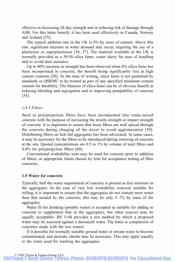
effective in increasing 28-day strength and in reducing risk of damage throughASR. For this latter benefit, it has been used effectively in Canada, Norwayand Iceland [55].
The typical addition rate in the UK is 8% by mass of cement. Above thisrate, significant increase in water demand may occur, requiring the use of aplasticizer or superplasticizer [56, 57]. The material available in the UK isnormally provided as a 50:50 silica fume: water slurry for ease of handlingand to avoid dust nuisance.
Up to 40% increase in strength has been observed when 8% silica fume hasbeen incorporated in concrete, the benefit being significantly less at highcement contents [58]. At the time of writing, silica fume is not permitted bystandards or QSRMC to be treated as part of any specified minimum cementcontent for durability. The fineness of silica fume can be of obvious benefit inreducing bleeding and segregation and in improving pumpability of concrete[55].
1.4.3 Fibres
Steel or polypropylene fibres have been incorporated into ready-mixedconcrete with the purpose of increasing the tensile strength or impact strengthof concrete. It is important to ensure that loose fibres are well spread throughthe concrete during charging of the mixer to avoid agglomeration [59].Distributing fibres on belt-fed aggregates has been advocated. In some cases,it may be necessary for the fibres to be introduced during remixing of concreteat the site. Quoted concentrations are 0.5 to 1% by volume of steel fibres and0.4% for polypropylene fibres [60].
Conventional workability tests may be used for concrete prior to additionof fibres, or appropriate limits chosen by trial for acceptance testing of fibreconcretes.
1.5 Water for concrete
Typically, half the water requirement of concrete is present as free moisture inthe aggregates. In the case of very low workability concrete suitable forrolling, it is important to ensure that the aggregates do not contain more waterthan that needed by the concrete; this may be only 5–7% by mass of theaggregates.
Water fit for drinking (potable water) is accepted as suitable for adding toconcrete to supplement that in the aggregates, but other sources may beequally acceptable. BS 3148 provides a test method by which a proposedwater may be assessed against a deionized water. The basis is comparison ofconcretes made with the two waters.
It is possible for normally suitable ground water or stream water to becomecontaminated, and periodic checks may be necessary. This may apply equallyto the water used for washing the aggregates.
© 1992 Taylor & Francis Group, LLC SOFTbank E-Book Center Tehran, Phone: 66403879,66493070 For Educational Use.

2 Properties of fresh concrete
Fresh concrete is concrete in a mouldable condition, able to be placed,compacted and finished by the chosen means. The properties of fresh concrete[61] which are of interest to the ready-mixed concrete producers and theirclients are uniformity, stability, workability, pumpability, water demand andwater/cement ratio, rate of change of workability, and finishability.
2.1 Uniformity and stability
Fresh concrete, properly designed, batched and mixed, needs to be sensiblyuniform and to remain reasonably so through the remaining normal processesof transporting, placing, compacting, finishing and thereafter, until thestiffening process of hydration provides the necessary rigidity. Extremeconstruction conditions may require additional precautions. The range ofrelative densities of the normal materials used, 1 for water to over 3 forcement, means that there is always a tendency for segregation to take place,particularly at high workability. This tendency will generally be smaller forricher mixes, finer cementitious materials, finer sands, higher sand contents,lower water demand concretes, in warm weather, and when air-entraining andcertain water-reducing admixtures are used. Agitation during transport orremixing before discharge of medium- and high-workability concrete may benecessary to maintain uniformity, whereas for low-workability mixes, agitationmay be detrimental, causing aggregation or ‘balling’ of the fine components.
High sand contents can produce a problem during compaction andfinishing, leading to the formation of a mortar layer at the surface if theconcrete is over-vibrated, over-tamped or over-trowelled. Very high sandcontents may also lead to a higher water content.
Some methods of handling during placing, such as dropping concretethrough a cage of reinforcing bars, are likely to produce segregation of coarserfrom finer components. The user needs to appreciate that well-designedconcrete will not overcome bad construction techniques.
Some bleeding of water is to be expected for most concretes, but excessivebleeding can result in significant settlement of the solid materials, and lead tocracking of the surface of concrete slabs over reinforcing bars and to ‘sand-runs’ on the vertical surfaces of walls or columns. Sometimes, the user ofconcrete takes into account the structural needs of the specification but ignoresconsideration of the fresh concrete. The cement content required for adequacy
© 1992 Taylor & Francis Group, LLC SOFTbank E-Book Center Tehran, Phone: 66403879,66493070 For Educational Use.

of finish can often be significantly higher than that needed for structuralstrength alone.
It is important for users to discuss with ready-mixed concrete producers anyspecial construction situation so that any modifications to mixes can bediscussed and agreed to combat adverse circumstances.
2.2 Workability
The term workability covers a wide range of properties [62]:
Mobility (ability for concrete to move around reinforcement and intorestricted spaces)
Compactibility (by hand or vibration)Finishability (of free or moulded surfaces)Pumpability (for pumped concrete).
In any given construction situation, a given concrete may perform well, whilein another situation it may perform less well. For example, a 40 mm maximumsize aggregate concrete may be much easier to vibrate than a 10 mm aggregateconcrete in a mass pour, but 10 mm concrete may be better in a narrowreinforced construction.
Greater importance may attach to different aspects of workabilitydepending on the type of construction:
Mass pour mCfThin slab, lightly reinforced mcFIntricately shaped structural section MCF
where m, c and f refer to the needs for mobility, compactability andfinishability and the size of letter refers to its relative importance.
It follows that no one workability test method can ever adequately suit allconstruction situations. This is why it is important that the selection ofworkability and test method is left by the specifier to the decision of thecontractor on the basis of his skill and experience of the type of constructionand the equipment he elects to use to place, compact and finish the concrete.
However, it is vital that the contractor decides upon the workability neededprior to the stage of enquiry, because the quotation from the ready-mixedconcrete supplier will be based upon the notified value. If at the order stage,for a designed mix, the contractor on site orders a higher workability, theready-mixed concrete supplier will need to adjust the mix from that whichformed the basis of quotation and adjust the price correspondingly.
2.2.1 Workability test methods
There are two reasons for the contractor specifying a workability methodtogether with an appropriate target value, and invoking corresponding
© 1992 Taylor & Francis Group, LLC SOFTbank E-Book Center Tehran, Phone: 66403879,66493070 For Educational Use.

compliance limits. They are:
(i) To control workability within a selected range appropriate to theconstruction conditions and equipment to be used for transporting, placingand compacting concrete
(ii) To control indirectly the water content and thus water/cement ratio of theconcrete.
The commonest method of test for both purposes is that for slump.Compacting factor is sometimes used for paving-quality concrete and the flowtest for self-compacting or flowing concrete. The Vebe test and Tattersall 2-point test [63] are sometimes used in research laboratories, where they servean important function in leading to a greater understanding of the mechanismswhich affect workability, but they are only rarely used in the field.
Figure 2.1 Summary of relations between slump, compacting factor and Vebe tests indicatingthe effect of aggregate/cement ratio. Redrawn and adapted from Dewar [64]
© 1992 Taylor & Francis Group, LLC SOFTbank E-Book Center Tehran, Phone: 66403879,66493070 For Educational Use.

The relationships between the different methods are dependent upon mixcharacteristics. Figure 2.1 shows how relationships are affected by aggregate/cement ratio for slump, compacting factor and Vebe time [64].
The compliance requirements in BS 5328 for the common workability testsare shown in Tables 2.1 and 2.2.
BS 5328 recognizes the practical difficulty that, in order to check concretefor compliance for slump, it is necessary to obtain a representative samplewhich would entail discharge of the complete delivery. To overcome thisproblem, spot sampling (see Fig. 7.1) from an early part of the discharge, after0.3 m3 has been discharged, is permitted for the slump test only, but withincreased tolerance. For compacting factor, for cube-making and for othertests, samples are required always to be fully representative, entailingsampling through the complete discharge (see Fig. 7.1).
The commonest specified slumps are 50 mm and 75 mm, both withtolerances of ±25 mm. The acceptable range of 25–75 mm for a specifiedslump of 50 mm is deceptively large. The slump test is so sensitive to variationin water content that for concrete to be within the allowed slump tolerance itwill need to be controlled to within -5% and +3% of the target water contentor water/cement ratio, which is very tight control indeed. At 75 mm slump thecontrol is even tighter, -3 to +2%. Thus, the slump test and its correspondinglimits are excellent and longstanding ways of controlling workability andwater content of concrete, although, regrettably, they are not alwaysrecognized as such.
Tables 2.3 and 2.4 provide guides for the contractor in the selection ofslump values for different purposes. Guidance in Table 2.3 is similar to thatgiven in BS 5328.
Table 2.1 Compliance requirements of BS 5328 for slump
Table 2.2 Compliance requirements of BS 5328 for compacting factor
© 1992 Taylor & Francis Group, LLC SOFTbank E-Book Center Tehran, Phone: 66403879,66493070 For Educational Use.

2.3 Pumpability
The ability of concrete to be pumped [67–69] relies on a combination of:
(i) Properties of the concrete(ii) Pipeline diameter and capability of the pump
Table 2.3 Selection of slump for different construction situations [65]
* See also Table 2.4.
© 1992 Taylor & Francis Group, LLC SOFTbank E-Book Center Tehran, Phone: 66403879,66493070 For Educational Use.

(iii) Construction situation—height of outlet; distance to be pumped; numberand angle of bends; continuity and rate of pumping.
As far as the concrete is concerned the prime properties are:
(i) Ratio of max aggregate size to pipeline diameter(ii) Workability(iii) Stability.
Generally, concrete will normally be pumpable if the following apply:
(i) Cement content is over 300 kg/m3 or the weight of cement plus fineaggregate below 300 micron is over 1.75×free water content.
(ii) Slump is over 50 mm, preferably target 75 mm(iii) Nominal maximum aggregate size not exceeding one-fifth of the pipeline
diameter, i.e. 20 mm for a 100 mm pipeline(iv) Fine aggregate content is up to 5% higher than for a normal well-
designed mix.
Concretes which bleed badly may be unpumpable. This may be overcome byadding more cement, pfa, finer sand or some water-reducing agents.Excessively cohesive concretes, particularly high cement content mixes, maybe unpumpable due to excessive friction. Increasing slump may help in thiscase. It may be necessary to reduce 10 mm content in a 20 mm aggregateconcrete, especially if the 10 mm material is flaky.
2.4 Water demand and water/cement ratio
The initial water demand of concrete is influenced by:
(i) Cementitious materials characteristics and content
Table 2.4 Selection of slump of flow values for cast-in-place piling.
Note: Slump and flow values do not necessarily correspond to eachother. The suitability of these values needs discussion between con-tractor and concrete supplier to take account of site conditions andpiling techniques.
© 1992 Taylor & Francis Group, LLC SOFTbank E-Book Center Tehran, Phone: 66403879,66493070 For Educational Use.
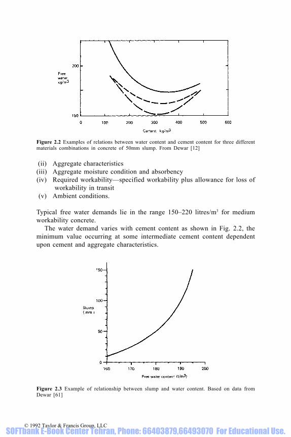
(ii) Aggregate characteristics(iii) Aggregate moisture condition and absorbency(iv) Required workability—specified workability plus allowance for loss of
workability in transit(v) Ambient conditions.
Typical free water demands lie in the range 150–220 litres/m3 for mediumworkability concrete.
The water demand varies with cement content as shown in Fig. 2.2, theminimum value occurring at some intermediate cement content dependentupon cement and aggregate characteristics.
Figure 2.2 Examples of relations between water content and cement content for three differentmaterials combinations in concrete of 50mm slump. From Dewar [12]
Figure 2.3 Example of relationship between slump and water content. Based on data fromDewar [61]
© 1992 Taylor & Francis Group, LLC SOFTbank E-Book Center Tehran, Phone: 66403879,66493070 For Educational Use.

No particular technical significance is attached to the minimum value andits corresponding cement content, because cement content will in allprobability be determined by considerations of strength and durability.However, it is possibly significant that the normal working range for cementcontent does lie around that producing the lowest water demand.
Water demand is only slightly affected by the ratio of fine to coarseaggregate, but can be significantly increased when the ratio is high comparedwith the optimum [12].
Higher temperatures of the environment and the materials increase thewater demand of the concrete, but the net effect on cement content for a givenstrength and slump is unlikely to be very great in the UK under normalconditions. A 17°C temperature rise required 2–6% increase in water, but lessthan 5 kg/m3 increase in cement content in recent US tests [70].
A relation between workability and water content is summarized in Fig. 2.3,and is sensibly independent of cement content [61]. However, the relationshipbetween water/cement ratio and workability is influenced by cement content[62] as is shown in Fig. 2.4.
The influence of time and transporting are considered in detail in thefollowing sections.
2.5 Rate of change of workability
All concretes can be expected to lose workability slowly with time due toeffects of hydration, associated temperature rise, evaporation, and, in the caseof dry aggregates, absorption of water [61, 71, 72]. These effects will be muchmagnified in the laboratory, so that totally misleading information on loss ofworkability with time can be obtained.
Figure 2.4 Example of effect of aggregate/cement ratio on relationship between slump andwater/cement ratio. After Newman [62]
© 1992 Taylor & Francis Group, LLC SOFTbank E-Book Center Tehran, Phone: 66403879,66493070 For Educational Use.

There are certain situations in real practice which can result in fast or flashstiffening of concrete:
(i) Extreme hot dry weather(ii) Use of very hot water for mixing in winter(iii) Excessive contents of accelerator, particularly calcium chloride (now
banned for use in structural concrete)(iv) Use of dry aggregates (particularly lightweight absorptive aggregate)(v) Cements with more rapid setting times (see also section 1.2)
(vi) Flash-setting cements (see also section 1.2)(vii) False-setting cements (see also section 1.2).
In the case of the false-setting cement, there is a fast loss of workability whichcan be regained if the concrete is remixed or vibrated [61] as showndiagrammatically in Fig. 2.5.
Provided the concrete is in the process of being mixed or can be remixed,which is normally not a problem with agitated ready-mixed concrete, theworkability is quickly regained. When false-set occurs with lean or lowworkability concrete transported in a truckmixer without agitation or by atipper, then it can create a problem which can only be overcome by havingsufficient drive power to commence agitation or by intense vibration duringplacing and compaction [61].
2.6 Influence of transporting on the workability of ready-mixed concrete
Ready-mixed concrete will be affected not only by time but by any factorsassociated with transporting. The effects of transporting may depend upon
Figure 2.5 Illustration of effect of remixing on workability of concrete which has suffered ‘falsesetting’
© 1992 Taylor & Francis Group, LLC SOFTbank E-Book Center Tehran, Phone: 66403879,66493070 For Educational Use.

whether the concrete is agitated in transit and whether it is remixed beforedischarge (see Table 2.5) [61].
Method 1 (Table 2.5) requires the plant supervisor to anticipate thenormally small effects in transit by adjustment of water content, and allows theworkability and water content of all deliveries to be controlled by oneexperienced operative. Method 2 is preferred by some ready-mixed concretecompanies, and requires water content to be adjusted and workability to bejudged by each truck driver at delivery. Method 3 is used for dry mixes,particularly dry-lean concrete, 3(b) being used commonly by customersemploying their own transport to collect low-workability concrete.
During transport, non-agitated concrete will tend to settle, compact and tosegregate, requiring expenditure of energy in remixing to return it to a looseworkable state and to regain uniformity. An exception would be low-workability lean concrete which would be relatively unaffected (but see falsesetting, section 1.2.4).
Agitation of concrete has the important function of counteractingsegregation and compaction during transport, and thus maintains uniformityand the bulked, workable state to the point of delivery. Airflow duringagitation might increase evaporation, leading to a reduction in workability.The friction caused by agitation could result in grinding, which in turn mightlead to an increased water demand and thus reduced workability. It is assumedthat heat developed during grinding is compensated for by the cooling effectof evaporation.
The action and interaction of all these factors, together with those describedin the previous section dealing with the influence of time, are summarized inFig. 2.6.The four major influences affecting workability are evaporation, hydration,absorption and grinding. Of these, probably both evaporation and hydrationaccelerate with time, depending upon ambient conditions. Absorption orgrinding are likely to produce significant effects only when exceptionally
Table 2.5 Mixing and transporting of ready-mixed concrete [61].
© 1992 Taylor & Francis Group, LLC SOFTbank E-Book Center Tehran, Phone: 66403879,66493070 For Educational Use.

Figure 2.6 Interaction between the various factors involved in transporting ready-mixed concreteand their effects on workability and strength. After Dewar [61]
© 1992 Taylor & Francis Group, LLC SOFTbank E-Book Center Tehran, Phone: 66403879,66493070 For Educational Use.

absorptive and dry aggregates or abradable aggregates are used.Another possible factor is grinding of cement particles [73]. It is not known
to what extent this occurs and whether the effects are significant, but grindingof cement particles would tend to increase the water demand of the freshconcretes of medium- and high cement contents and thus reduce theirworkability. It may even be possible in a lean mix, due to shortage of fineparticles, for grinding of cement to have the reverse effect by reducing waterdemand, and for an increased workability to be observed.
The effects of the main factors in reducing workability can be consideredin three separate ways associated with the water content of the concrete:
(i) Increasing the water demand, e.g. by increased fineness(ii) Extracting water from the paste by evaporation or absorption, resulting
in a reduced effective water/cement ratio(iii) Decreasing availability of water in the paste for workability, e.g. by
hydration, without changing the water/cement ratio.
Due to the interaction of the various influences, the rate of reduction in
Table 2.6 Internal influences on the effects of transporting concrete [61].
Table 2.7 External influences on the effects of transporting concrete[61].
© 1992 Taylor & Francis Group, LLC SOFTbank E-Book Center Tehran, Phone: 66403879,66493070 For Educational Use.

workability increases with time, generally, but may not produce losses ofpractical significance until several hours after the initial mixing.
This rate of reduction in workability is influenced by internal and externalconditions, as indicated in Tables 2.6 and 2.7. Some of these influences arediscussed in more detail in the remainder of this section.
2.6.1 Cement content
Mixes of lower cement content lose workability at a lower rate because therate of temperature rise is less and a smaller proportion of water is utilized inthe hydration process during a given time. This is illustrated in Fig. 2.7.
2.6.2 Aggregate grinding
Some aggregates, particularly limestone fine aggregate or weakly cementedsandstone, are likely to be abraded slightly during agitation, resulting inincreased fineness and higher water demand. Where necessary, this could beoffset by reducing slightly the initial fine/total aggregate ratio of the mix.
2.6.3 Water content and initial workability
Mixes of higher water content or initial workability lose workability at a lowerrate because the effect of a given water loss, due to evaporation or hydration,will be diluted. This is illustrated in Figs. 2.8 and 2.9.
2.6.4 Admixtures
Admixtures may influence the heat development, hydration or air content andmay thus influence the rate of loss of workability. In particular, calcium
Figure 2.7 Effect of aggregate/cement ratio on rate of loss of workability with time. After Dewar[61]
© 1992 Taylor & Francis Group, LLC SOFTbank E-Book Center Tehran, Phone: 66403879,66493070 For Educational Use.

chloride (rarely permitted) may increase appreciably the rate of hydration andtemperature rise, leading to rapid stiffening, particularly when rich dry mixesare transported in hot weather. Because the early rate of loss of workability isusually due primarily to evaporation, retarders may not have a significanteffect until a later stage when hydration becomes dominant. Thus retarderswill tend to influence the later rate but not the early rate of loss of workability.The air content of air-entrained concrete may also change with time, resultingin increased or decreased workability.
2.6.5 Ambient conditions
Low air or materials temperatures decrease the rates of hydration andevaporation, and thus decrease the rate of loss of workability. The normalrange of temperature of cement is unlikely to cause significant effects, butvery high values may contribute to problems with rich mixes in hot weather.
Figure 2.8 Effect of water/cement ratio on rate of loss of workability with time. After Dewar [61]
Figure 2.9 Effect of initial value on rate of loss of workability [61]
© 1992 Taylor & Francis Group, LLC SOFTbank E-Book Center Tehran, Phone: 66403879,66493070 For Educational Use.

Obviously, high humidity of the air decreases the rate of evaporation andconsequent loss of workability.
Wind speed possibly has only a small influence on protected concrete in adrum, but becomes more important during discharge and placing, when theconcrete is unprotected.
2.6.6 Bulk volume of concrete
Larger volumes of concrete have a lower surface area/volume ratio and are lesssusceptible to large losses in water due to evaporation or to loss of a significantproportion of mortar through adherence to the drum or its blades. On the otherhand, large volumes retain heat more easily and may produce a higher rate ofhydration. It is not known how all these aspects interact in detail with each otherto affect loss in workability, but practical experience suggests that large volumeslose workability at a significantly lower rate than small volumes.
2.6.7 Transporting method
It is probable that different transporting methods will produce different effectsbut it seems unlikely that Methods 1 and 2 (see Table 2.5) will produce effectswhich are seriously different, because a long period of low-speed agitationmay be considered to be equivalent in its effects to a short period of high-speed mixing.
Obviously, uncovered concrete transported by Method 3(b) may suffergreater effects at the surface due to evaporation, but is protected internally.
2.7 Effects of transporting of concrete on compressive strength andworkability
To assist with discussions on limitations of delivery time and retempering, itis essential to consider the interrelated effects of transporting on strength andworkability. Strength has been found to increase generally with time at about5% per hour of agitation, if the concrete can be compacted fully at thedecreased workability [71].
Figure 2.6 indicates that, when damp aggregates are used, concrete strengthincreases only through evaporation, but that workability decreases because ofother effects as well. Thus, the relation between strength and workability fora given mix, as initial water content is altered, can be expected to change withtime of agitation, as confirmed by actual test results summarized in Fig. 2.10.
This effect is generally quite small for typical transporting times andconditions in the UK but becomes more important for very long periods ofagitation, rich mixes, low initial workabilities and in hot dry weather.
In practice, the effects even though small are taken into account in the
© 1992 Taylor & Francis Group, LLC SOFTbank E-Book Center Tehran, Phone: 66403879,66493070 For Educational Use.

design of concrete because design data are usually based on strength andworkability tests made at delivery and not at the plant.
2.8 Limitations on delivery time
Misconceptions concerning the mechanisms of setting or stiffening havecaused fears that there is a particular time after which it is detrimental tocontinue working fresh concrete. Technical education, particularly by theBritish Ready Mixed Concrete Association and Cement and ConcreteAssociation, has now largely overcome this problem.
It is true that for each mix and particular means of compaction there willbe a time after which concrete will be losing workability at too great a rate toallow full compaction to be obtained. This limiting time will depend on themix and on the external conditions, and will be longer for lean, high-workability mixes, in cold weather and when vibration is employed.
There will also be a time, depending again on the mix and conditions, when
Figure 2.10 Effect of agitation time on the relation between strength and workability. AfterDewar [61, 71]
Table 2.8 Approximate times of agitation after which therate of loss in compacting factor exceeds 0.05 per hour,under average conditions.
© 1992 Taylor & Francis Group, LLC SOFTbank E-Book Center Tehran, Phone: 66403879,66493070 For Educational Use.

the strength obtained at the specified workability is significantly lower thanthat obtained for concrete placed immediately after mixing. However, it isusually impractical to specify different time limits for different mixes andconditions.
Some specifications provide a single time limit, covering all mixes andconditions, which is easy to comprehend and enforce and is intended to allowthe contractor sufficient time subsequently to place and compact the deliveredconcrete without appreciable change in workability occurring. If the time limitis not unduly restrictive, problems will not usually occur for the producer. BS5328, for example, requires ready-mixed concrete to be delivered within twohours of mixing when agitated, or one hour if not agitated.
The reasonableness of this simple approach can be assessed for averageambient conditions from Tables 2.8 and 2.9. For example, if a time limit oftwo hours is specified then, from Table 2.8, most concretes delivered at thespecified workability within this time would not be losing workability at anexcessive rate and, from Table 2.9, no excessive strength loss would beexpected compared with concrete of the specified slump placed soon aftermixing.
Again, it is worth stressing that when concrete quality control is based onsamples taken from delivery, any effects of time on workability or strength areaccounted for automatically. In any event, in the UK it is very rare for deliverytimes to approach the maximum allowed time of two hours.
2.9 Retempering of concrete
Water properly mixed with fresh concrete at some time after the initial mixingbehaves as if it had been added initially [71]. Thus, retempering could be usedto restore workability to the specified value, provided the water can be mixedintimately with the mass of concrete. This will normally be possible only whena truckmixer is used to transport the concrete.When concrete is observed at delivery to have a lower workability than
Table 2.9 Approximate times of agitation at which astrength reduction of 2 N/mm2 occurs below that forconcrete of the same slump but compacted shortly aftermixing.
© 1992 Taylor & Francis Group, LLC SOFTbank E-Book Center Tehran, Phone: 66403879,66493070 For Educational Use.

specified, there are three possible reasons:
(i) Insufficient water batched initially(ii) Higher rate of evaporation (or absorption) than anticipated(iii) Higher rate of hydration (or grinding) than expected.
Retempering water added to offset (i) or (ii) will not result in a lower strengththan expected, whereas extra water to combat (iii) will result in a lowerstrength. However, in examining concrete at delivery it will not be possible todetermine which reason applies.
Under average conditions, hydration should only start to producesignificant effects after the times shown in Tables 2.10, so that retempering forany of the three reasons could be carried out with reasonable confidencewithin these times. If a slight loss in strength is acceptable due to (iii), thetimes could be relaxed to those given in Table 2.9, so that for nearly all mixesretempering within the normally specified maximum delivery time of twohours would be acceptable.
As an extra safeguard, it might be advisable for the producer to limit thequantity of retempering water to some maximum value, say, 6 litres/m3, whichis approximately 3% of the total mixing water requirement. This would thenlimit any strength reduction to less than 2 N/mm2. From Fig. 2.3, retemperingof 25 mm slump concrete with 6 litres of water per m3 would allow the slumpto increase to 35–40 mm, well inside the tolerance of 25–75 mm for 50 mmspecified slump.
Some confirmation of the reasonableness of this approach is provided byFig. 2.11, where ready-mixed concrete has been retempered with extra waterfor two hours to maintain slump, without strength dropping below the initiallevel [131].
Policy within the ready-mixed concrete industry varies regardingretempering. Some companies, particularly those requiring all water to be addedat the plant, do not allow concrete to be retempered unless the extra water issigned for by the customer’s representative. This has the advantage of protecting
Table 2.10 Approximate times of agitation after whichthe relations between strength and workability commenceto deviate significantly from those for concrete placedshortly after mixing
© 1992 Taylor & Francis Group, LLC SOFTbank E-Book Center Tehran, Phone: 66403879,66493070 For Educational Use.

the customer by restricting the unauthorized addition of extra water to produce ahigher workability than specified. For other companies, when water is alwaysadded at site it is not possible to distinguish between mixing water andretempering water since they are added at the same time. It is, however, possibleto restrict the total amount of water added to some fixed amount, and this isusually done; any extra will again require a signature from the customer. BS5328 requires that all additional water is recorded on the delivery ticket.
2.10 Laboratory simulation of ready-mixed concrete
Difficulties occur in attempting to simulate ready-mixed concrete throughlaboratory tests. Small-scale experiments may reproduce faithfully thequalitative effects, but may overestimate grossly the quantitative effects ofmixing, time or agitation [61].
Regrettably, much research intended to simulate ready-mixed concrete hasbeen wasted by not taking this point into account. During the first few hours,when using dry aggregates in laboratory mixes, most loss of workability is dueto absorption and evaporation, coupled with loss of moisture and finematerials on mixing and testing equipment.
Figure 2.11 Effect on strength of retempering concrete with additional water to maintainapproximately 50 mm slump for up to 3h. Redrawn and adapted from Beaufait [131]
© 1992 Taylor & Francis Group, LLC SOFTbank E-Book Center Tehran, Phone: 66403879,66493070 For Educational Use.

The following factors may need to be taken into account in the planning ofsmall-scale experiments and in the interpretation of data and conclusions frompast research in the laboratory relating to ready-mixed concrete:
(i) Volume of concrete(ii) Exposed surface area/volume ratio(iii) Mixer/agitator power, rpm and mixing action(iv) Water absorption by dry aggregates(v) Water absorption, evaporation and loss of mortar in coating the drum
and blades and the sampling and testing equipment(vi) Abrasion or crushing of aggregates dependent on mixer power and blade
configuration.
To ensure validity of conclusions in respect of mixing, agitation or time, it isessential that tests are made on full-scale mixes using normal productionequipment and conditions.
© 1992 Taylor & Francis Group, LLC SOFTbank E-Book Center Tehran, Phone: 66403879,66493070 For Educational Use.

3 Properties of hardened concrete
3.1 Surface quality
The surface quality achieved is a perfect mirror of the combined effects ofconcrete specification, concrete quality provided, the quality of the formwork(in the case of vertical faces and soffits) and the qualities of supervision andworkmanship in placing, compacting, curing and finishing of the concrete.
Commonly specifications for concrete concentrate on strength anddurability, ignoring surface finish. C & CA advice for high standard finish ofconcrete includes a recommendation for a minimum cement content of 320 kg/m3 [74]. An earlier more detailed C & CA publication advised a cementcontent between 355 kg/m3 and 475 kg/m3 for 20mm aggregate concrete [75].
So-called sand-runs (or scouring) on vertical surfaces are to be expectedwhen lean mixes, low grades and high workabilities are specified. Theproblem will be increased in cold weather and with deep lifts. The problem iscaused by bleeding of water up the face of the formwork. It may be difficultto minimize the occurrence of surface blowholes when formwork isimpermeable, when concrete is air-entrained or when rich mixes are employed.Comparing the different advice given in relation to blowholes and sand-runsleads to the conclusion that minimizing the risk of one fault will increase therisk of the other. This needs to be taken into account in selecting a solution.When colour variation must be minimized, ensuring that materials are alwaysfrom a single source will usually be necessary, to complement the manyaspects of site construction which must be under strict control.
Detailed advice on diagnosis and control of blemishes is provided in C &CA Appearance Matters No. 3 [76].
3.2 Cracking of concrete
All concretes crack, indeed if they did not, there would be something wrong,because the mechanisms of cracking and creep can be thought of as importantmeans by which stresses in a heterogeneous material readjust themselves.Fortunately, most of the cracking is on a microscopic scale and does notconstitute a normally visible fault.
Concrete, like the human body, can tolerate some degree of damage and isalso self-healing. The mechanism, known also as autogeneous healing, permitshydration products to form in water-filled cracks, so sealing them. As a result,
© 1992 Taylor & Francis Group, LLC SOFTbank E-Book Center Tehran, Phone: 66403879,66493070 For Educational Use.

Table 3.1 Classification of non-structural cracks. Modified from [77]
© 1992 Taylor & Francis Group, LLC SOFTbank E-Book Center Tehran, Phone: 66403879,66493070 For Educational Use.

cracks in foundations and even in water-retaining structures can often betolerated.
Some cracks, however, are not only visible but may be unacceptable eitherstructurally, aesthetically or because of influences on durability orserviceability, and may require expensive remedial treatment.
Cracks may be initiated in plastic, stiffening or hardened concrete. Theircauses could be many and various and they may be difficult to diagnose. Fig.3.1 provides graphic guidance on the more common types of non-structuraland structural cracks, and Table 3.1 provides a summary of the potentialcauses of non-structural cracks, together with preventive measures. For moredetailed information on diagnosis and remedial measures, readers arerecommended to consult the Concrete Society Report [77].
To avoid cracking of the surface of sloping slabs, it is important forcompaction and finishing to be directed up the slope, which is against gravityand the natural inclination of the operative.
Figure 3.1 Examples of cracks in a hypothetical concrete structure. Redrawn and adapted fromConcrete Society [77]
© 1992 Taylor & Francis Group, LLC SOFTbank E-Book Center Tehran, Phone: 66403879,66493070 For Educational Use.

3.3 Strength
The strength of concrete is both a key structural attribute and also a measureof the development of hydration by which many other properties can also beexpected to improve with time. Thus strength has become the most commonlyspecified and tested property of hardened concrete.
Of the various strengths which might be measured, the compressivestrength of cubes made, cured and tested at 28 days in a standard way hasbecome the accepted means by which quality is assessed and other propertiesestimated. Only very occasionally are other strengths actually measured,reliance being placed on empirical relationships, e.g. between compressivestrength and tensile [78], flexural, shear or bond strengths. These strengths aretypically an order of magnitude lower than compressive strength.
Periodically, attempts are made to promote tensile strength testing, butprecision so far has been too poor for use for compliance purposes, as may beseen from Fig. 3.2.
Typical values for cube strength range up to 70 N/mm2; higher values areachieved only with selected cements and aggregates, by the use of water-reducing admixtures, by accepting lower workability or waiting beyond 28days [79].
The range of relationships of strength with cement content or with water/cement ratio in the UK is quite wide for dense aggregate concrete, because ofthe range of cement and aggregate qualities which are in use, as may be seenfrom Fig. 3.3. The curves are based on survey data for 75 mm slump concreteobtained by BRMCA in 1980 [80, 81]. The flattening of the curves at highstrengths is a function of the aggregate strength, cement capability andbonding of cement to aggregate, coupled with influences of both aggregateand cement on water demand for a stated workability in the case of the
Figure 3.2 Distribution of differences between mean tensile strengths obtained on a range ofcommercial testing machines and results obtained on a reference machine. After Ryle [132]
© 1992 Taylor & Francis Group, LLC SOFTbank E-Book Center Tehran, Phone: 66403879,66493070 For Educational Use.

cement-content curves. As the particular ‘ceiling’ strength is approached, thebenefit of increasing cement content is progressively reduced so that,eventually, further increase produces negligible benefit. In the middle of therange, 1 N/mm2 gain in strength may be obtained by increasing cement contentby 4–8 kg/m3, depending on the particular materials combination.
Relationships between strength and cement content are very complex, andinvolve cement hydration and water demand chracteristics, proportions of thevarious components, bond between the cement hydration products and theaggregate particles, strength of the aggregate particles, strength of the cementhydration products, influence of admixtures, air content, compaction, curingand age. The relative importance of each factor varies with the strength levelbeing considered.
There is a tendency for the rounder smooth aggregates to produce highstrengths at low cement contents, because of the benefit to water demand,whereas the stronger crushed rocks may tend to produce the highest strengths athigh cement contents. Thus it is possible for relationships for two aggregateswith the same cement to intersect at some intermediate cement content.
Figure 3.3 Range of relationships between (left) cement content and strength and (right) strengthand water/cement ratio. After Dewar [80, 81]
© 1992 Taylor & Francis Group, LLC SOFTbank E-Book Center Tehran, Phone: 66403879,66493070 For Educational Use.

3.3.1 Strength development with age
Under standard curing, concrete cubes develop strength very quickly, thegreatest gain being observed in the first few days, with progressively less gainon each subsequent day, although gain may still be observed even after 10years and more.
While this continued gain is reassuring to all concrete users, the length oftime to achieve most of the ultimate strength would be rather long incontractual terms, so that an age of 28 days has emerged as a workablecompromise for the basis of specification requirements. However, this is stilltoo long for contractors and specifiers to wait before making decisions toremove forms, to stress concrete or to continue with further construction.Equally for the ready-mixed concrete producer, 28 days is too long to waitbefore taking action to remedy a production problem.
To overcome these problems, use is often made of relationships betweenearly and 28-day strengths to enable early action to be taken. For example,contractors will often use 7-day strengths, and the ready-mixed concreteproducer will use 7-day or even 1-day accelerated strengths [82–84],equivalent to 7 days’ normal curing, in quality control systems.
It is important to know the relationships between early and 28-day strengthsfor the particular cement and aggregate combination in use, and to monitor therelationship. It is not sufficient merely to assume a value, to assume that thevalue determined at a medium level of strength applies at low or high levels,or that the value obtained from cement test data will necessarily be the samefor the aggregates used in practice.
3.4 Durability
Concrete is a heterogeneous mixture of differing materials, some inert andsome reacting, continually changing with age. This heterogeneity and mobilityis at the same time both advantageous and a pitfall for the unwary. Concreteis amazingly versatile and capable of overcoming many of the misuses andmishandling to which it is subjected. Yet at the same time it is oftenmisunderstood, abused and subjected to a lack of care which may fail to allowit to achieve anywhere near its full potential [85].
Concrete is more than a material, it is a complete process with changingcontrol at different stages in the process. Specification to meet a need is the firststage and raw materials production is the second. The mix formulation, mixingof the fresh concrete and transporting to the construction form the third stage,and the placing, compaction around reinforcement and early curing make up thefourth. The fifth stage is maturing in the construction environment, the sixth isfunctioning under action of the working load and environment.
Each of the stages may involve different organizations and individuals whowill influence subsequent performance in the final stage by their skills and
© 1992 Taylor & Francis Group, LLC SOFTbank E-Book Center Tehran, Phone: 66403879,66493070 For Educational Use.

care. A lack of care in one stage can nullify all the care in each of the others,but when the media identify faults in concrete, it is concrete which is blamed,not that part of the concreting process which is at fault.
Where durability is concerned, the evidence of distress is that seen easily atthe surface. This is usually because of two reasons, both self-evident. Firstly,only surface distress is easily observable, and secondly, most, although not all,durability problems start and end at or near the surface rather than at the heart.If we consider why this second observation is so common, again it should beself-evident that external aggressive agencies can more easily attack the surfacethan elsewhere. What may be slightly less evident is that the surface is where thelack of care in the fourth and fifth stages of concrete construction can wreakhavoc. The surface is the Achilles heel of concrete [85].
3.4.1 Concrete mobility
Concrete is mobile with time, both chemically and physically, and in the freshand hardened state. This mobility can be both helpful and harmful.
During and after compaction, air and water move upwards in the fresh andstiffening concrete. The benefit is a reduction in the porosity of the concrete. Onthe debit side, a water/cement ratio gradient develops. The permeability in thevertical direction can be increased by capillary channels which start as anetwork of tiny streams of water, developing into rivers in the heart and onvertical faces, into estuaries and even into an ocean at the top surface. Thisocean, when it occurs, has a side benefit in providing some necessary water forcuring but it is offset by a weakening of the surface. Of course, good concretingpractice can minimize extreme effects but some effect will almost always occur.
Through sedimentation, which is the process of settlement of the fineparticles of cement and sand, tiny flaws may develop under coarse aggregateparticles and reinforcing bars.
In the stiffening and hardening concrete, continuous or spasmodic hydrationhelps to reduce permeability and seals cracks by autogenous healing.Hydration increases temperature. Thermal and moisture movements causeexpansion, shrinkage, tensile, compressive and differential stresses, creep andcracking.
Despite all these events, concrete is an accommodating material, adaptinggenerally very well, almost in spite of whether the mechanisms and the needfor care are understood. Most of the flaws will be at the microscopic level andvery few create obvious visible defects, but it is important not to be lulled bythis into a false sense of security. Aggressive agencies can identify theseweaknesses and take advantage of them.
In the hardened state, movement continues. Air, water vapour and fluidsmay enter and move around in concrete, evaporating water, depositing ordissolving chemicals or diluting solutions and relocating chemicals. Inreinforced concrete, concrete variations, moisture variations, chemical
© 1992 Taylor & Francis Group, LLC SOFTbank E-Book Center Tehran, Phone: 66403879,66493070 For Educational Use.

migration and carbonation will change the electropotential distribution, whichin turn may encourage electrochemical reactivity, ideal for corrosion. Loading,wind speed, daily and annual temperature changes, humidity changes, groundmovements and water levels will all change the stress and strainconcentrations.
Concrete can have a different permeability horizontally compared withvertically because of the effects of sedimentation and microscopic cracking.Compaction may be variable, due to the difficulty of compacting concrete wellat edges and corners and near boxed-out areas, and between reinforcement andthe surface. Concrete can have cracks in the heart which are invisible at thesurface. Cracks at the surface may not progress far into the concrete, or theymay go right through.
3.4.2 Covercrete and heartcrete
As a result of the mobile nature of concrete, variations in the concrete itself,and variations in compaction and curing, concrete construction will display avariation in properties over its surface and its cross-section, as shown, forexample, in Fig. 3.4.
In order of quality, ‘heartcrete’ will usually be the strongest, and thesurfaces, more particularly the top surface, will usually be the weakest. Thedifferences can be very large. For durability it is now thought best toconcentrate on the ‘cover’. Durability is only skin deep, because of thelocation of the reinforcement near this cover layer (Fig. 3.5).
Figure 3.4 Effects of water gain and lack of curing leading to different qualities of concrete inan rc beam
© 1992 Taylor & Francis Group, LLC SOFTbank E-Book Center Tehran, Phone: 66403879,66493070 For Educational Use.

Figure 3.5 Construction aspects involved in the durability of ‘covercrete’
Figure 3.6 Example of the effect of poor curing on the humidity gradient within concrete at anage of 7 days. Redrawn and adapted from Spears [86]
© 1992 Taylor & Francis Group, LLC SOFTbank E-Book Center Tehran, Phone: 66403879,66493070 For Educational Use.

The outer 25 mm or so may be an order of magnitude more permeable thanthe heart, due to poor protection and lack of curing. The upper 20% of theheight may have a substantially greater permeability due to water gain (seesection 3.4.1).
The influence of poor curing on the humidity of covercrete can be judgedfrom Fig. 3.6, from an American report [86], which indicates that, even asearly as 7 days, as much as 15 mm of the cover depth may be below 80%relative humidity, the minimum level accepted as necessary for continuedhydration.
3.4.3 A background to specifying durability
It is rarely possible for specifiers to draft or for producers to acceptspecifications which refer directly to durability on a performance basis. Thereasons are, firstly, that there are few recognized tests that can be used as abasis, and, secondly, that the concrete producer cannot easily take account ofthe unknown factors associated with workmanship and conditions of serviceunder which the concrete will be expected to function and over which theconcrete producer has no influence.
The commonest ways used by specifiers to overcome this problem are tospecify designed mixes with one or more of the following requirements:
(i) Strength grades selected for durability(ii) Minimum target cement content(iii) Maximum target water/cement ratio(iv) Maximum target cement content(v) Type of cementitious material: special cement, ggbs, pfa
(vi) Total air content of an air-entrained mix(vii) Admixtures.
in addition to essential precautions such as concrete cover and curing.The assumptions being made by the specifier are that, by specifying
boundary values, usually selected from BS codes of practice, e.g. BS 8110 forstructural concrete for buildings, appropriate to the severity of the exposure,then the chemical resistance and pore structure of the concrete in the actualconstruction will be adequately resistant for a chosen life of the structure.Naturally considerable imprecision is involved, and where the specifier fails tosupervise the construction, optimism may be misplaced.
In respect of the quality of concrete provided to the construction, theabsence of adequate tests which could be used by the specifier to confirm thatthe specified values were being met led BRMCA, BACMI, CMF and BCA todevelop equivalent strength grades which could be used to reasonablyguarantee minimum cement contents and water/cement ratios anywhere in theUnited Kingdom. Equivalent grades are detailed and discussed further insection 4.6.
© 1992 Taylor & Francis Group, LLC SOFTbank E-Book Center Tehran, Phone: 66403879,66493070 For Educational Use.

Air-entrainment to provide resistance to frost attack and reducedpermeability is considered under admixtures (section 1.3). Sulphate resistanceis considered under cementitious materials (section 1.2).
As an alternative to a designed mix, the specifier may prescribe a mix fordurability as follows.
(i) Target cement content(ii) Type of cementitious material: special cement; ggbs; pfa(iii) Total air content of an air-entrained concrete(iv) Admixture.
3.4.4 Corrosion of reinforcement
To limit the risk of corrosion of reinforcement, BS 5328 has providedrecommendations correlating degrees of exposure, grade, minimum cementcontent and maximum W/C coupled with limitations on chloride content. BS8110 extends the correlation to include cover to the reinforcement.
3.4.5 Chlorides in concrete
BS 5328 bans calcium chloride in concrete to contain embedded metal andrecommends the limits in Table 3.2 for chloride content from other sources.
When these limits are invoked by specifiers, control of chloride content ofaggregates will usually be necessary and, in the case of the very low limits forprestressed concrete, it may mean that marine aggregates cannot be usedwithout very special precautions. It will also be necessary to account forchloride in cement, admixtures and water.
3.4.6 Alkali-silica reaction
In many satisfactory concretes, some reaction can be detected between alkalis,mainly from cements, and reactive forms of silica in the aggregates. Onlywhen the reaction, which is expansive, causes significant stresses and cracking
Table 3.2 Summary of main BS 5328 recommendations in respect of chloride content
* Inclusive of ggbs or pfa
© 1992 Taylor & Francis Group, LLC SOFTbank E-Book Center Tehran, Phone: 66403879,66493070 For Educational Use.

of the concrete is it necessary to consider alkali-silica reaction (ASR) asdeleterious. Fortunately, in the UK, serious damage due to this reaction has sofar been reported only in the southwest and Midlands.
While specifiers in areas which are apparently safe may not consider thenecessity for any special precautions, those in affected areas and those dealingwith major structures where the conditions are likely to approach those knownto have the potential for producing damage, may consider that someprecautions should be taken.
The three conditions causing damaging ASR are moist condition of theconcrete, sufficient alkali, and reactive silica.
All three need to occur before serious ASR will be manifested by disruptionof the concrete. The alkalis originate primarily in the cement, but there is thepossibility of significant contributions from other sources such as ggbs, pfa,admixtures or sea water.
The problem is considered under aggregates (section 1.1) and cement(section 1.2), further detailed advice is provided in the Concrete SocietyReport [22] and BRE digest 330 [145].
The alternative means of guarding against damaging ASR are as follows:
(i) Ensure concrete remains dry in service(ii) Use a source of Portland cement of declared alkali level of 0.6% or
below*(iii) Use a sulfate-resisting Portland cement of guaranteed alkali content
below 0.6%*(iv) Use a combination of Portland cement and ggbs or pfa, with a total
reactive alkali content of the cementitious material of 0.6% or less*(v) Use at least 50% ggbs in the cementitious material, either added at the
mixer or as a composite cement where the acid soluble alkali content ofthe cement or combination does not exceed 1.1% Na2O equivalent
(vi) Use a combination of Portland cement and at least 25% ggbs or pfa andensure that the reactive alkali content of the concrete is 3 kg/m3 or less
(vii) Ensure the cement and ggbs or pfa content does not exceed a valuecalculated from the reactive alkali level of the materials to maintain thealkali level of the concrete at 3 kg/m3 or below
(viii) Use aggregate and cement combinations with a known satisfactoryhistory
(ix) Use aggregate combinations known to be unreactive (see aggregatessection).
Experts are not in agreement over the most appropriate method for calculatingthe reactive alkali content for ggbs or pfa. Alternative methods based on watersolubility and acid solubility are provided in BS 5328, and it is essential tocheck the basis of limits given in specifications. * Provided that active alkalis from sources other than the cement do not exceed 0.2% by massof cement.
© 1992 Taylor & Francis Group, LLC SOFTbank E-Book Center Tehran, Phone: 66403879,66493070 For Educational Use.

4 Mix design
4.1 Principles of mix design
The general purpose of concrete mix design for a specific contract and use isto select materials and their proportions which will meet, economically, theproperties of the concrete in both the fresh and hardened states.
For ready-mixed concrete in general, the purpose is extended, refined anddivided into stages [80, 87].
(i) Materials selectionTo select materials which will meet most economically therequirements of most specifiers and intended uses,
(ii) Mix proportioningTo select proportions, in anticipation, to cover the range of all likelyspecifications and uses To determine the total quantities of materialsto ensure the ordered concrete volume is provided To produce batchdata for the production of the full range of possible mixes andvolumes which might be ordered To produce mix data to ensuredesigns are instantly available,
(iii) Mix selectionTo select the most appropriate mix to meet the specified requirementand intended use, taking account of the latest feedback from thequality control systems To provide additional data for special mixdesigns not covered by the above.
This total approach is much more comprehensive and sophisticated than thatof the classic Road Note No. 4 or the present DoE Design of Normal ConcreteMixes [88], for which the main use is to allow a quick first assessment of apossible solution, with only limited availability of information on the materialsand their performance.
Ready-mixed concrete is treated as a multi-component material, and themore sophisticated approach enables optimum proportioning to be achieved,resulting in the most economic composite solution for any given specificationand use.
4.2 BRMCA method of concrete mix design
The BRMCA method [80, 87] has been developed over many years, has beenadopted throughout the industry and has been used in the production and
© 1992 Taylor & Francis Group, LLC SOFTbank E-Book Center Tehran, Phone: 66403879,66493070 For Educational Use.

control of many hundreds of millions of cubic metres of concrete. The methodis in widespread use by members of the Quality Scheme for Ready MixedConcrete, and ensures that valid technical data are available to concrete usersto substantiate the properties and quantities of concrete mixes being suppliedfrom QSRMC Depots. The main stages in the BRMCA method are illustratedby a simple flowchart (Fig. 4.1).
A key feature of the BRMCA method is that in Stage II (Fig. 4.2), mixesare designed for optimum performance in the plastic state to ensure that theconcrete is suitable for transporting, handling, compacting and finishing. As aresult, a percentage of fine to total aggregate is decided upon for each mixwhich will provide sufficient cohesion, with a margin of safety, to minimizethe risk of serious segregation under normal handling of the concrete. Onlywhen the technologist is satisfied with the designs are the hardened propertiesof the mixes determined in Stage III for the laboratory method (Fig. 4.3), orfrom tests in production. In the alternative production batch method fordetermining strength, concrete is sampled from a substantial number ofproduction batches over a wide range of cement contents during a period of12 months.
The analysis and recording of trial mix and strength test data in Stage IV(Fig. 4.4) are based on cement content as the primary mix parameter to whichall other mix constituents and concrete properties are directly related. The keyrelationships are illustrated, for typical materials, in Fig. 4.5, a–f.
Figure 4.1 Major stages of the BRMCA method of mix design. After Dewar [80]
© 1992 Taylor & Francis Group, LLC SOFTbank E-Book Center Tehran, Phone: 66403879,66493070 For Educational Use.

The key relationships derived in Fig. 4.4 are those between (i) cementcontent and the major specified concrete properties (Fig. 4.5 a–d, f) and (ii)cement content and the weight of each constituent in the mix (Fig. 4.5e).
4.2.1 Use of base data from BRMCA mix design method
For use in concrete production, the base data shown graphically in Fig. 4.5eare stored in tables or graphs and in batch books or computer memory, inincrements of cement content of either 5 or 10 kg/m3 for the typical productionrange of mixes from 100 to 450 kg/m3. The base data provide the idealproportioning of mix constituents to achieve specified concrete properties, thecorrect batching instruction for the production of mixes, and provide the basisfor altering mix proportions to achieve different values of workabilities andspecial concrete properties. They enable the key parameters for every
Figure 4.2 BRMCA mix design method Stage II-design for plastic properties. After Dewar [80]
© 1992 Taylor & Francis Group, LLC SOFTbank E-Book Center Tehran, Phone: 66403879,66493070 For Educational Use.

Figure 4.3 BRMCA mix design method Stage III-performance of hardened concrete. AfterDewar [80]
Figure 4.4 BRMCA mix design method Stages IV, analysis and presentation and V, use of mixdesign data. After Dewar [80]
© 1992 Taylor & Francis Group, LLC SOFTbank E-Book Center Tehran, Phone: 66403879,66493070 For Educational Use.

Figure 4.5 Typical relationships for one material combinations: reference slump 75 mm,maximum aggregate size 20 mm. After Dewar [80]
© 1992 Taylor & Francis Group, LLC SOFTbank E-Book Center Tehran, Phone: 66403879,66493070 For Educational Use.

combination of materials to be estimated, e.g. water/cement ratio or plasticdensity.
The relationship between cement content and strength allows the selectionof a mix to satisfy any specified strength requirement when account is takenof the following aspects, amplified in Chapter 6 on quality control:
(i) In selecting the cement content of a designed mix, a target mean strengthhas to be selected that exceeds the specified characteristic strength by adesign margin which includes a statistical constant and the depotstandard deviation, in the following way:
where design margin=depot standard deviation×k(ii) The value of the statistical constant k is selected according to the
proportion of test results that are permitted to fall below the specifiedstrength and to accord with the specified compliance rules.
(iii) Typically, a value for k of 2 is adopted by the producer to satisfycompliance rules of BS 5328 or BS 8110 (CP 110 revised), but onoccasion a higher value may be selected to build in additional safety.Incidentally, the principle of characteristic strength, adopted by BS8110, requires k to be only 1.64.
(iv) In all cases where designed mixes are supplied, the producer has theresponsibility of controlling the quality of the concrete so that thecompliance requirements are satisfied. To achieve this objective, theproducer operates a QSRMC-approved control system which comparesthe results of tests on samples of materials and concrete with theperformance of the materials and concrete on which the mix design wasbased.
(v) The producer adjusts the proportions of the mix to correct for anysignificant deviation between these measurements.
(vi) The concrete control system also provides a current value of standarddeviation for use in the formula.
(vii) The cement content is adjusted to take account of the workabilityspecified relative to that adopted, usually 50 or 75 mm, in establishingthe relationship.
The continuous measurement and analysis of data in the control system toensure compliance with specifications and British Standards also ensure thatthe relationships derived in the trial mix programme are continuouslyconfirmed and the need for any modification swiftly identified.
The use of base data from the BRMCA method of mix design fordetermining the batch weights per cubic metre of concrete for a designed mixspecification is illustrated by the example in section 4.2.2 following.
target mean = specified+designstrength strength margin
© 1992 Taylor & Francis Group, LLC SOFTbank E-Book Center Tehran, Phone: 66403879,66493070 For Educational Use.

4.2.2 Example: selecting batch proportions for specified design mixrequirements [80, 87]
Select batch quantities for a designed mix to BS 5328 for a typical mixrelationship derived using the BRMCA method. Specified strength gradeC30, maximum free water/cement ratio 0.50 and slump 50 mm (see Fig. 4.6).Step 1: Select target mean strength TMS
TMS=30+(SD×k)k=2 for BS 5328 compliance rulesUse SD=5.0 N/mm2 from quality control information for standard deviationTMS=30+(5.0×2)= 40 N/mm2
Step 2: Read off cement content for TMS of 40 N/mm2. 300 kg/m3
Step 3: Read off cement content for free W/C ratio of 0.50 360 kg/m3
Step 4: Use highest cement content from step 2 or step 3 360 kg/m3
Step 5: Read off mix quantities per cubic metrefor cement content of 360 kg/m3 cement 360 kg/m3
Fine aggregate* 620 kg/m3
Coarse aggregate* 1200 kg/m3
Free water 180 kg/m3
* Saturated and surface dry
Note: In this typical example, a cement content of 360 kg/m3 is required toachieve the specified free W/C ratio of 0.50 which will achieve a mean 28-daystrength of about 50 N/mm2 (Step 6).
4.2.2.1 Benefit of specifying a higher grade. For the particular materials in theexample, specification of a BS 5328 strength grade C40 (50 N/mm2 less
Figure 4.6 Mix design example. After Dewar [80]
© 1992 Taylor & Francis Group, LLC SOFTbank E-Book Center Tehran, Phone: 66403879,66493070 For Educational Use.

margin of 10 N/mm2) instead of C30 would enable the free water/cement ratioof 0.50 to be assured by testing the concrete for strength compliance inaccordance with BS 5328.
4.2.2.2 Adjustments to batchweights to allow for moisture content ofaggregates. Because aggregates are almost invariably batched at a highermoisture content than the saturated and surface dry (ssd) condition, it will benecessary to increase the batched weight of the fine and coarse aggregates bytheir respective free moisture contents, to ensure the correct ssd weights. Theamount of water needed to be added by the batcherman will be reducedcorrespondingly. Using the designed mix example and assuming 7% freemoisture in the fine aggregate and 3% free moisture in the coarse aggregate,the adjustments to the batch figures would be as follows:
4.2.3 Selection of batch proportions for a prescribed mix
Batch proportions for a prescribed mix are made using a process similar tothat in the following example for a BS 5328 standard mix.
4.2.4 Example: selecting batch proportions for a standard mix
Select batch quantities for a standard mix to BS 5328 for a typical mixrelationship derived using the BRMCA Method. ST4 mix 20 mm aggregate,75 mm slump (see Table 4.1 and Fig. 4.7).
Step 1: Select cement content from Table 4.1 for ST4 mix 300Step 2: Read off mix quantities for cement content of 300 kg/m3
cement 300 kg/m3
fine aggregate (ssd) 700 kg/m3
coarse aggregate (ssd) 1160 kg/m3
water (free) 180 kg/m3
© 1992 Taylor & Francis Group, LLC SOFTbank E-Book Center Tehran, Phone: 66403879,66493070 For Educational Use.
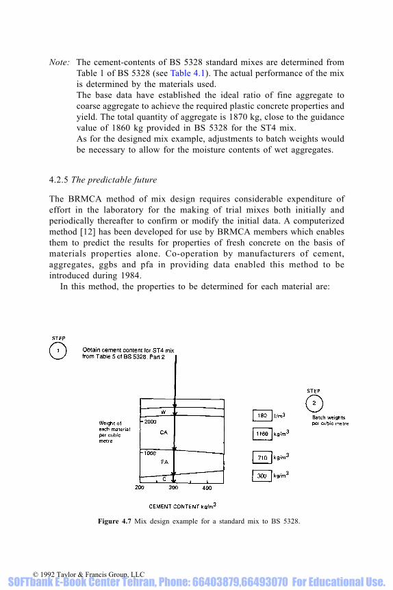
Note: The cement-contents of BS 5328 standard mixes are determined fromTable 1 of BS 5328 (see Table 4.1). The actual performance of the mixis determined by the materials used.The base data have established the ideal ratio of fine aggregate tocoarse aggregate to achieve the required plastic concrete properties andyield. The total quantity of aggregate is 1870 kg, close to the guidancevalue of 1860 kg provided in BS 5328 for the ST4 mix.As for the designed mix example, adjustments to batch weights wouldbe necessary to allow for the moisture contents of wet aggregates.
4.2.5 The predictable future
The BRMCA method of mix design requires considerable expenditure ofeffort in the laboratory for the making of trial mixes both initially andperiodically thereafter to confirm or modify the initial data. A computerizedmethod [12] has been developed for use by BRMCA members which enablesthem to predict the results for properties of fresh concrete on the basis ofmaterials properties alone. Co-operation by manufacturers of cement,aggregates, ggbs and pfa in providing data enabled this method to beintroduced during 1984.
In this method, the properties to be determined for each material are:
Figure 4.7 Mix design example for a standard mix to BS 5328.
© 1992 Taylor & Francis Group, LLC SOFTbank E-Book Center Tehran, Phone: 66403879,66493070 For Educational Use.

Mean size (determined from the grading)Voids ratio (determined for aggregates from tests for
bulk density and relative density;determined for powders from standardconsistence tests of pastes)
Relative density
The values for each material are processed by computer by use of acomplex mathematical model which assesses the effects of combining themtogether in concrete. This leads to a computer output of optimized mixproportions over the full range of possible cement contents and water/cementratios. The optimization ensures correct proportioning for adequate cohesionand correct yield.
An example of the accuracy of prediction is shown in Table 4.2 whereactual laboratory trial mix data are compared with predictions from materialsproperties. From such predictions, computerized batch book data covering thefull range of cement content and batch size can be prepared. The method canbe used for confirming existing batch data, for updating existing batch data orfor producing new data for new materials and plants.
4.2.6 Technical advice on concrete properties based on the BRMCA method
On request, and as required by BS 5328, purchasers of ready-mixed concretemay be supplied by the producer with data derived from the mix design process.In addition, the concrete producer is able to advise on a wide range of concreteproperties and uses by developments from the base data, for example:
Table 4.1 Extract from BS 5328 for standard mixes
Note: The values for total aggregate are for guidance only
© 1992 Taylor & Francis Group, LLC SOFTbank E-Book Center Tehran, Phone: 66403879,66493070 For Educational Use.

Uses of concrete PumpingFlowing concreteSpecial handling,
placing and compactionOther materials Aggregate size
and performance Special aggregatesAdmixturesggbs or pfa.
4.3 Mix design using ggbs or pfa
Cement, fine and coarse aggregates provide a three-component solids systemenabling void content, and thus water demand, to be minimized byappropriate selection of mix proportions of the three solid components. Thisis an essential part of the skill of the ready-mixed concrete technologist whois responsible often for tens of thousands of cubic metres of optimizedconcrete annually.
The advent of other cementitious materials such as ggbs or pfa, far frombeing a nuisance, provide an opportunity for the mix designer to show his skillfurther with a four-component solids system, enabling further reduction invoidage and water demand.
For ggbs or pfa concretes, either a similar comprehensive mix designapproach is adopted, or well-tried adjustments are made to accurate plainconcrete mix quantities to allow for the properties and proportions of ggbs orpfa to be used, as in the example below for pfa mix design.
4.3.1 Example: an adjustment to a mix design for the use of pfa [38]
It is required to modify the quantities per cubic metre of a plain concrete,known to meet the specified strength, to include 30% of pfa by weight ofcementitious material and to have the same slump and 28-day strength. It isassumed that the following data have been accumulated for a particular qualityof pfa to BS 3892: Part 1 and for this level of pfa inclusion.
Increase in cementitious material=12%Water content reduction= 5%
Relative density of cement=3.12Relative density of pfa=2.25
Relative density (SSD) of fine aggregate=2.59Relative density (SSD) of coarse aggregate=2.50
Standard deviation is assumed unaffected
© 1992 Taylor & Francis Group, LLC SOFTbank E-Book Center Tehran, Phone: 66403879,66493070 For Educational Use.

Table 4.2 Comparison of actual concrete test data with data estimated by computerized simulation based on current materials tests [80]
© 1992 Taylor & Francis Group, LLC SOFTbank E-Book Center Tehran, Phone: 66403879,66493070 For Educational Use.

It may be noticed that, for the pfa concrete, the total cementitious material isgreater but the OP cement content is smaller, the fine aggregate content isreduced, the coarse aggregate content is deliberately the same, the water isreduced and the density is reduced because of the lower density of pfa comparedwith cement.
© 1992 Taylor & Francis Group, LLC SOFTbank E-Book Center Tehran, Phone: 66403879,66493070 For Educational Use.

Note that it should not be assumed that ggbs concretes or other pfa concreteswould require the same adjustments. The factors can differ appreciably betweenmaterials, sources and qualities and will be influenced by the proportion of ggbsor pfa, the cement content and other factors. The method, however, will beapplicable and can be used for any situation, provided the factors are known.
4.4 Judging concrete mix design
A major difficulty exists for the inexperienced specifier in finding a standardagainst which to judge a proposed mix design. He may, quite naturally, reachfor a copy of the excellent ‘Design of normal concrete mixes’ [88] and bequite dismayed to discover that the estimated mix proportions bear noresemblance to those being proposed. The usual reasons are that, for the initialdesign, ‘Design of normal concrete mixes’ assumes:
(i) Constant water content over the complete range of cement content forconstant slump
Figure 4.8 Comparison of assumed relationship from ‘Design of normal concrete mixes’ andrange of actual relationships in 1980 for ready-mixed concrete. After Dewar [80]
© 1992 Taylor & Francis Group, LLC SOFTbank E-Book Center Tehran, Phone: 66403879,66493070 For Educational Use.

(ii) Relatively low cement strengths compared with typical values availabletoday.
The first assumption was made for simplicity, but can lead to appreciableerror. The second generally leads to appreciable over-estimation of cementcontent. This was quite deliberate, ensuring safe designs for use with almostany materials anywhere in the UK, and has been further affected by increasedcement strength since publication of the booklet. When the initial design isfollowed by laboratory mixes, as recommended by the booklet, appreciableadjustments will normally be found to be required.
Specifiers may find it useful to compare proposed mix designs with theenvelope of data in Fig. 4.8 obtained from a survey made by BRMCA in 1980for 75 mm slump concrete. Also superimposed on this diagram is a typicalrelationship from ‘Design of normal concrete mixes’. The distribution ofrelationships from the survey was not symmetrical, so that a greater proportionoccurred in the upper part of the band. Thus, typically, there is a greaterprobability of the specifier finding a present-day mix design in this upper part.However, in some areas of the UK it is possible for the combination of cementand aggregate qualities to yield a relationship towards the lower boundary.
Note that Fig. 4.8 relates achieved mean strength to cement content.Commonly, target mean strength is set about 10 N/mm2 higher than thespecified strength.
4.5 Water/cement ratio—free or total
Water/cement ratio can be measured either in terms of free or total water, thedifference being the water absorbed by the aggregate. The difference can besignificant, so that it is important for the specifier to make clear the basis (freeor total) and to query the basis of mix design data when it is not made clearwhich is being quoted by the producer.
So, for example, if total W/C is 0.56, A/C is 6 and percentage absorption forthe combined fine and coarse aggregate is 1%, then
‘Free W/C’ is usually assumed to be the effective water/cement ratio inconcrete determining the particle spacing of cement in concrete andinfluencing porosity, permeability, durability and strength of the concrete.
© 1992 Taylor & Francis Group, LLC SOFTbank E-Book Center Tehran, Phone: 66403879,66493070 For Educational Use.

Unfortunately, it is difficult to measure ‘free W/C’ accurately, and virtuallyimpossible to measure it directly. Reliance has to be placed upon indirectmeasurement via total water content and aggregate absorption, which isdependent upon the subjective assessment of the saturated and surface-dry(SSD) condition of the aggregate.
4.6 Meeting durability requirements
Generally, specification requirements for durability are written in terms ofminimum values for cement content and maximum values for free water/cement ratio. Values for these parameters estimated to meet strength andworkability requirements are checked by the producer against the specifiedlimits before making final mix design proposals.
Very often limits set for cement content and water/cement ratio entailachieving a much higher strength than the grade specified, so that the specifiercannot use observed compliance with specified strength as a means of assuringhimself that the limits set for durability have been met.
4.6.1 Equivalent strength grades—ensuring durability
The absence of simple and accurate tests which can be used by the purchaserto check whether the concrete complies with a specified minimum cementcontent or maximum water/cement ratio has been a cause of concern to theresponsible ready-mixed concrete producer.
To overcome this problem, BRMCA, in co-operation with BACMI, theCement Makers Federation and the BCA, developed the concept of national orequivalent grades by which strength grades can be specified which have betterthan 95% probability of ensuring compliance in the UK with any specified
Table 4.3 Equivalent grades for 10 to 40 mm aggregate, cement of 42.5 strength class to BS 12and 500 to 150 mm slump
*For guidance only
© 1992 Taylor & Francis Group, LLC SOFTbank E-Book Center Tehran, Phone: 66403879,66493070 For Educational Use.

cement content or water/cement ratio [81, 89]. Examples of such nationallyapplicable grades included in BS 5328 are shown in Table 4.3.
By selecting the highest appropriate grade for his needs, the specifier mayuse cube tests to confirm that the cement content and free water/cement ratiohave a very high probability of being in compliance anywhere in the UK.Some approximate indications of the mean strengths corresponding to thevarious grades are also provided in Table 4.3, to aid judgement. BS 8110 hasadopted grades compatible with this table.
© 1992 Taylor & Francis Group, LLC SOFTbank E-Book Center Tehran, Phone: 66403879,66493070 For Educational Use.

5 Statistics for quality control, mixdesign and compliance
A knowledge of certain aspects of statistics is essential for understanding andoperating quality control and mix design of ready-mixed concrete. A fargreater knowledge is required for assessing the implications of complianceclauses in specifications. In this section, an introduction is provided to helpthose involved in quality control and mix design, and to show some relevantresults of using more complex concepts in assessing BS 5328 complianceclauses.
5.1 Statistical terms
Various statistical terms and measurements, developed by mathematicians andstatistical practitioners, are common to the assessment and control of variationof many measured parameters for a wide range of natural and manufacturedmaterials or products.
The terms most commonly encountered are:
VariationRepeatability and reproducibilityPrecision and toleranceDistributionNormal distributionHistogramMeanRangeStandard deviationCoefficient of variationOperating characteristic
5.2 Variation
If one technician prepared a number of representative samples of concretefrom one batch of concrete and measured the slump twice on each sample, itwould be very unlikely that each of any pair of slump values would beidentical or that all the mean values of the pairs from the different sampleswould be the same. If the same technician repeated the test but used a differentstandard slump cone or a second technician made tests at the same time, it
© 1992 Taylor & Francis Group, LLC SOFTbank E-Book Center Tehran, Phone: 66403879,66493070 For Educational Use.

would again be unlikely that identical results would be obtained. In answer tothe question: ‘What is the slump of the batch of concrete?’ each technician cansay only ‘My estimate of slump is…’.
If the first technician now goes on to test many different batches of concrete,all intended to be identical, different slump values will again be obtained. Thedifferences will be due now not only to the inherent variation of the test but alsodue to real variations in slump between the different batches. Tolerances aboutspecified slumps are provided to take account of both types of variation.
Similarly, if the technician makes air tests or casts cubes, the results willshow variation in air content or strength, some of the variation being due tothe method of sampling and testing and some being due to variation inproperties between different batches of concrete.
British standards for concrete testing increasingly provide data onrepeatability and reproducibility, which are both aspects of precision. The firstterm relates to variation associated with the individual and the equipmentused, the second to variation between individuals, laboratories and equipment.Data on precision enable tolerances to be determined for inclusion inspecifications.
The precision of a result cannot be assessed from a single test, which iswhy British Standards rarely permit a single test result to be used forcompliance purposes. Because of the imprecision of some tests, BritishStandards may insist on obtaining a number of results, only the average ofwhich may be used to assess compliance. Even so, tolerances often need to bequite wide to account for imprecision.
5.3 Distribution
If results of cube strength are compared for different batches of the same mixdesign, they may or may not be seen to be grouped in any particular way, butas the number of results increases, a pattern or distribution will usually emergeof the type shown in Fig. 5.1. The block diagram, called a histogram, can beseen to peak near the middle, fewer results occurring as one moves away fromthe middle. The diagram is sensibly symmetrical: whatever happens on theleft, also happens on the right.
5.4 Normal distribution
The symmetry and shape of Fig. 5.1 are completely normal and would beexpected to occur for many other measurements on materials, not only withconcrete. In fact, they are so normal that mathematicians have discoveredmathematical laws by which the shape can be drawn on the basis of just onemeasurement, called standard deviation, the calculation of which is shownlater. The standard deviation is usually about 1/4 to 1/6th of the spread of thecomplete histogram, provided there are plenty of results in it. For the
© 1992 Taylor & Francis Group, LLC SOFTbank E-Book Center Tehran, Phone: 66403879,66493070 For Educational Use.

histogram in Fig. 5.1, the standard deviation can be shown to be 5 N/mm2,which accords with the spread observed of about 30 N/mm2.
Mathematical laws predict that the proportion of results lying withinvarious limits on either side of the middle will be as in Table 5.1. Because
Figure 5.1 Comparison of the theoretical distribution and a histogram for 100 cube results whenstandard deviation is 5 N/mm2 and the mean is 30 N/mm2. Note: The histogram has beenobtained by counting the numbers of results in columns 2.5 N/mm2 wide. The numbers areindicated at the top of each column.
Table 5.1 Proportion of results expected to lie between pairs of limits.
© 1992 Taylor & Francis Group, LLC SOFTbank E-Book Center Tehran, Phone: 66403879,66493070 For Educational Use.

concrete strength obeys the same laws applicable to other measurements, wewould expect to find reasonable agreement between the theoretical proportionsand the actual proportion of results, as is shown to be the case in Table 5.1.The theoretical proportions of results below any limit less than the mean valuecan be obtained from Table 5.2. It will be seen from Fig. 5.1 that 3% of resultsare below 20 N/mm2 close to the 2.5% expected from theory for a limit2×standard deviation below the mean. Note that in this case the mean is 30 N/mm2 and the standard deviation is 5 N/mm2.
5.5 Calculations of mean, standard deviation and other parameters
The formulae for calculating mean and standard deviation are:
There are derived formulae for use in calculators or computers which will givethe same answers. There are also graphical methods [90]. The expression inthe numerator of the formula for standard deviation is shorthand for sum ( S)of squares ( )2 of differences (~) between each result (x) and the mean ( ). The‘minus one’ in the denominator of the formula is a correction to produce thebest estimate of standard deviation, to allow for the fact that the true value ofthe mean is not known, ( ) being only an estimate.
Calculators, and of course computers, can be used to calculate mean andstandard deviation quickly with minimum risk of error, provided the correctdata are fed in. It is necessary to check that the formula used by the calculatoror computer contains (n-1) and not (n) in the denominator. Use of the (n-1)formula will be necessary when small numbers of results are involved, but asn increases in size, so the error is reduced and might safely be ignored. Anaccurate assessment of standard deviation requires a substantial number ofresults, never less than 25 and preferably 100 or more.
To understand how the formula operates, an example is provided in Table
Table 5.2 Proportions of results expected to lie below a lower limit.
© 1992 Taylor & Francis Group, LLC SOFTbank E-Book Center Tehran, Phone: 66403879,66493070 For Educational Use.
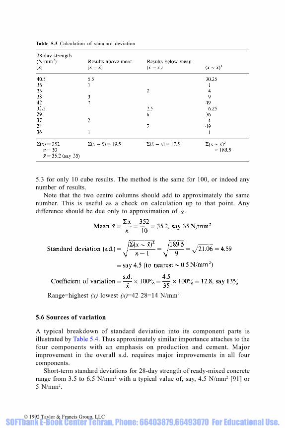
5.3 for only 10 cube results. The method is the same for 100, or indeed anynumber of results.
Note that the two centre columns should add to approximately the samenumber. This is useful as a check on calculation up to that point. Anydifference should be due only to approximation of .
Range=highest (x)-lowest (x)=42-28=14 N/mm2
5.6 Sources of variation
A typical breakdown of standard deviation into its component parts isillustrated by Table 5.4. Thus approximately similar importance attaches to thefour components with an emphasis on production and cement. Majorimprovement in the overall s.d. requires major improvements in all fourcomponents.
Short-term standard deviations for 28-day strength of ready-mixed concreterange from 3.5 to 6.5 N/mm2 with a typical value of, say, 4.5 N/mm2 [91] or5 N/mm2.
Table 5.3 Calculation of standard deviation
© 1992 Taylor & Francis Group, LLC SOFTbank E-Book Center Tehran, Phone: 66403879,66493070 For Educational Use.
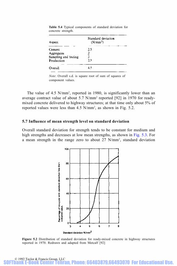
The value of 4.5 N/mm2, reported in 1980, is significantly lower than anaverage contract value of about 5.7 N/mm2 reported [92] in 1970 for ready-mixed concrete delivered to highway structures; at that time only about 5% ofreported values were less than 4.5 N/mm2, as shown in Fig. 5.2.
5.7 Influence of mean strength level on standard deviation
Overall standard deviation for strength tends to be constant for medium andhigh strengths and decreases at low mean strengths, as shown in Fig. 5.3. Fora mean strength in the range zero to about 27 N/mm2, standard deviation
Table 5.4 Typical components of standard deviation forconcrete strength.
Figure 5.2 Distribution of standard deviation for ready-mixed concrete in highway structuresreported in 1970. Redrawn and adapted from Metcalf [92]
Note: Overall s.d. is square root of sum of squares ofcomponent values.
© 1992 Taylor & Francis Group, LLC SOFTbank E-Book Center Tehran, Phone: 66403879,66493070 For Educational Use.

increases proportionally with mean strength, which implies that coefficient ofvariation is constant in this range, whereas above 27 N/mm2, standarddeviation is constant [41]. Ready-mixed concrete depot standard deviation isnormally measured on concrete of mean strength above 27 N/mm2, and thusquoted standard deviation values can usually be assumed to represent moststructural concrete production.
In the special case of very lean low-workability concretes, variation due tocompaction can be very significant, so that it is unwise to assume that lowerstandard deviations are applicable without confirmation directly from relevanttest data.
5.8 Standard deviation due to sampling and testing
Standard deviation due to sampling and testing alone seems to varyproportionally with mean strength over the full range of strength, and thus ismore significant for high-strength concrete.
The coefficient of variation for careful laboratory sampling and testing ofcubes is approximately 3%. Thus standard deviation is about 1 N/mm2 at amean strength of 30 N/mm2, and 2 N/mm2 at 60 N/mm2 under ideal conditions.Appreciably higher values can occur with poor site sampling and testing.
Figure 5.3 Assumed relationship between standard deviation and mean strength of concrete
Table 5.5 Influence of standard deviation due to sampling and testing, on the observed overallstandard deviation for strength of ready-mixed concrete.
© 1992 Taylor & Francis Group, LLC SOFTbank E-Book Center Tehran, Phone: 66403879,66493070 For Educational Use.

The importance for the producer of achieving a low standard deviation forsampling and testing in order not to inflate the observed overall standarddeviation for ready-mixed concrete may be seen from Table 5.5. If thestandard deviation is high for sampling and testing made on behalf of thepurchaser for compliance, this can result in a misleading impression of aproducer’s ability to control uniformity. It may also lead to apparentcompliance failures.
5.9 Relevance of standard deviation for concrete mix design
For designed mixes, it is necessary to estimate a target mean strengthsubstantially in excess of the specified strength to reduce the risk of failingcompliance clauses in specifications to an acceptably low level. Complianceclauses in BS 5328 are based on providing an acceptably low risk to thespecifier of receiving more than 5% of concrete below the specified strength.Historic and recent experience have indicated that design for an average of97.5% of concrete above the specified strength is an acceptable balance forthe producer between economy and risk of failing the compliance clauses.
From Table 5.2 it will be apparent that, if the margin between target meanand specified strength is 2×standard deviation, the requirement of 97.5% ofresults above will be met. Thus, the well-tried formula is
target mean strength=specified strength+(2×standard deviation)
where standard deviation is the plant standard deviation for target valuesabove 27 N/mm2, and as follows for target values below 27 N/mm2 (seeFig. 5.3):
where C is the specified strength.For example, if C=15 N/mm2
5.10 Statistical implications of compliance rules
The purpose of a compliance rule is to provide a means by which the clientcan judge, with an acceptably low risk of error, whether complying concretehas been provided. It is normal today to do this in two ways: by providing onerule for every tested batch and a second rule covering a group of tested
© 1992 Taylor & Francis Group, LLC SOFTbank E-Book Center Tehran, Phone: 66403879,66493070 For Educational Use.

batches together with all those untested in between. Normally these are writtenas absolute or ‘go-no go’ rules rather than rules permitted to be failed a smallproportion of the time. The unfortunate result is that, although the risk of anybatch failing is a known constant, the probability of failure occurring at sometime during a contract increases with the size of the contract. Naturally, therisks could be reduced by increasing the margin for larger contracts.
If the producer designs for 97.5% of concrete to be above the specifiedstrength when the theoretical basis of the compliance rules is 95%, the risk offailing at all on any normal size of contract can be shown to be acceptably low.Thus, by this approach, the ready-mixed concrete industry runs less risk ofproblems with each individual small contract and also safeguards largercontracts and its overall production.
The conventional way by which probabilities may be judged by bothproducer and consumer is through the use of the type of diagram called anoperating characteristic curve (Fig. 5.4). For any compliance clause, theproducer may assess the risk of having complying concrete rejected(producer’s risk) and the consumer can assess the risk of accepting non-complying concrete (consumer’s risk) [93, 94].
In the theoretical diagram (Fig. 5.4a), the producer’s risk and consumer’srisk are both nil. In practice, diagrams are usually of the form of Fig. 5.4b,where both run some risk.
Note that the statistics associated with the construction of operatingcharacteristic curves are not within the scope of this book—see [95], [101].
It is important not to treat as failures those batches of concrete representedby the 2.5% or 5% of results falling below the specified characteristicstrength. They are permitted to occur. Indeed, their achievement is successfuldesign, not failure. Only batches or sets of batches which fail complianceclauses are eligible to be treated as failures and their future subject to furtherconsideration.
Note that 5% of results below the specified strength is an acceptablesituation because this is actually the structural design criterion. Only theoccurrence of more than 5% below constitutes a potential violation ofstructural criteria.
5.10.1 Current compliance rules of BS 5328
The current strength compliance rules of BS 5328 are
(i) No result for a batch shall be less than the specified strength less 3 N/mm2
(ii) No mean of four consecutive results shall be less than the specifiedstrength plus 3 N/mm2
where a result is the mean for a pair of cubes from a single batch and testedat 28 days. BS 5328 also includes rules for the means of the first two and thefirst three results.
© 1992 Taylor & Francis Group, LLC SOFTbank E-Book Center Tehran, Phone: 66403879,66493070 For Educational Use.

Figure 5.4 Ideal and practical operating characteristic curves for a compliance rule showingproducers’s risk (of having concrete rejected) and consumer’s risk (of accepting unsatisfactoryconcrete)
© 1992 Taylor & Francis Group, LLC SOFTbank E-Book Center Tehran, Phone: 66403879,66493070 For Educational Use.

Purists and even some practitioners will quite correctly point out that thevalue of 3 N/mm2 used in each rule should really be some function of standarddeviation. However, standard deviation can only be calculated accurately bythe purchaser well into a large contract, and a value would have to be providedby the producer from his own data, which is tantamount to requiring him tomake his own hangman’s rope. The impracticality of this solution has resultedin the adoption by BSI of a constant addition or subtraction. Any slightadvantage or disadvantage associated with high or low standard deviations isfar outweighed by the simplicity of operating the rules in practice.
The producer/consumer risks may be seen for applications of each clauseseparately in Figs. 5.5 and 5.6. Account has been taken of the wording of thesecond clause, which permits it to be applied up to four times to each testedbatch and up to three times to intermediate untested batches. Obviously, thegreater the rate of compliance testing and of the application of a clause, andbecause of the ‘go-no go’ nature of the clause, the greater is the risk ofconcrete failing at some time during a contract. Also, under the ‘means offour’ clause, when testing is spread, the number of untested batches at riskunder a single decision could have serious implications.
As a result, the future of a large quantity of concrete construction could beat risk, dependent upon the results of a few tested batches. The commercialconsequences could be devastating as a result of a chance event, an error inproduction or inattention to correct sampling and testing by the purchaser.
BS 5328 attempts to cover this aspect by requiring the rate of testing to bedeclared by the specifier and also by limiting the maximum quantity ofconcrete at risk under a single application of the clause. When the sameconcrete is assessed by compliance clauses more than once, the producer’srisk is substantially increased.
Figure 5.5 Producer’s and consumer’s risks for BS 5328 compliance rule (a) relating toindividual results. Redrawn and adapted from Dewar [87]
© 1992 Taylor & Francis Group, LLC SOFTbank E-Book Center Tehran, Phone: 66403879,66493070 For Educational Use.

It will be seen from Fig. 5.7 that there is a very low probability of a trouble-free contract when the contract is large unless the design proportion below thespecified strength is reduced appreciably below the 5% permitted, and it mayneed to be below the usual 2.5%, unless a high risk is accepted by theproducer.
Interesting situations can arise with multiple assessments over a period of
Figure 5.6 Producer’s and consumer’s risks for BS 5328 compliance rule (b) relating to themeans of four results. Redrawn and adapted from Dewar [87]
Figure 5.7 Probability of a trouble-free contract under application of BS 5328 compliance clause(b) relating to means of four results. Based on data from Dewar [87]
© 1992 Taylor & Francis Group, LLC SOFTbank E-Book Center Tehran, Phone: 66403879,66493070 For Educational Use.

time. For example (see Table 5.6), in the case of four consecutive assessments,the same concrete can be judged to comply on three occasions and fail on thefourth, by which time further construction may have hidden it. The possiblesite scenarios are left to the reader’s imagination and ingenuity.
5.10.2 Influence on producer’s risk of faults in sampling and testing forcompliance
The importance for the producer of standard sampling, specimen-making,storing and testing by the consumer or his representatives cannot be toostrongly emphasized.
If non-standard techniques have been used which depress the results forstrength by as little as 0.5×standard deviation, the proportion of results belowthe specified strength can change from an expected 2.5% to 7% and alter theprobability of failing compliance with the BS 5328 ‘mean of four’ clause(overlapping application) from 2% to 10% or more—see Fig. 5.6 and [95].
BS 5328 now requires that the range of the two cubes made from the samebatch should not differ by more than 15% of the mean of the pair.
Table 5.6 Example of application of the BS 5328 clause (b), ‘means of four’, to successive cuberesults for grade C20 concrete
Note: Criterion of acceptance is 20+3=23 N/mm2 for mean of four.
© 1992 Taylor & Francis Group, LLC SOFTbank E-Book Center Tehran, Phone: 66403879,66493070 For Educational Use.

6 Quality control
The term ‘quality control’ means different things to different people. It issometimes thought to be synonymous with the whole area of quality assuranceor may merely be restricted to analyses of test data. The following definitionsmay clarify the meanings used here for ready-mixed concrete.
Quality Assurance: the operation of systems by which the client can beassured that control is being applied over all aspects of the completeprocess from enquiry to delivery to ensure compliance of the product withthe specification agreed with the client. This involves the wholemanagement team and their staffs together with independent inspection.
Figure 6.1 Control laboratory. Courtesy ARC Ltd
© 1992 Taylor & Francis Group, LLC SOFTbank E-Book Center Tehran, Phone: 66403879,66493070 For Educational Use.

Quality control: the operation of procedures to maintain product quality atthe selected level. This involves decisions and actions by technical,production and general management.Production control: quality control during production together withoperation of preventive measures by production staff.Quality monitoring: measurement of quality and advising of necessarychanges to maintain quality at the selected level—operated by technical andproduction staff on raw materials and products.
Quality control, production control and quality monitoring are covered in thissection.
Quality control of ready-mixed concrete can be divided into threeconvenient areas [96–98]: forward control, immediate control, andretrospective control. All three include technical and production aspects anduse of external data.
6.1 Forward control
Forward control and consequent corrective action are essential aspects ofquality control.
Figure 6.2 Site testing. Courtesy Pioneer Concrete (UK) Ltd
© 1992 Taylor & Francis Group, LLC SOFTbank E-Book Center Tehran, Phone: 66403879,66493070 For Educational Use.

Forward control covers:
(i) Materials storagePrevention of contaminationReliable transfer and feed systemsDrainage of aggregatesPrevention of freezing
(ii) Monitoring of qualities of materialsVisual checks—acceptance/rejectionSampling TestingCertification by suppliersInformation from suppliers
(iii) Modification of mix designs(iv) Plant maintenance(v) Transfer and weighing equipment
Controlled flowCalibrated weighscalesSeparate weighing of cementCalibrated admixture dispensers
(vi) Plant mixers and truck mixersBlade conditionMixer powerMaintenance.
Examples of properties of aggregates and cements covered by such monitoringare provided in the corresponding materials sections.
6.2 Immediate control
Immediate control is concerned with instant action to control the quality of theconcrete being produced or that of deliveries closely following. It covers thefollowing.
(i) Weighing (correct reading of batch data and accurate weighing)(ii) Visual observation of concrete during production and delivery or during
sampling and testing of fresh concrete (assessment of uniformity,cohesion, workability; adjustment to water content)
(iii) Use of equipment at the plant designed to measure moisture content ofaggregates, particularly fine aggregate, or the workability of the concrete
(iv) Making corresponding adjustments at the plant automatically ormanually to batched quantities to allow for observed, measured orreported changes in materials or concrete qualities.
(v) Inspection at delivery by driver and customer for uniformity andworkability; adjustments to workability within company policy.
© 1992 Taylor & Francis Group, LLC SOFTbank E-Book Center Tehran, Phone: 66403879,66493070 For Educational Use.

6.3 Retrospective control
Retrospective control covers
(i) Sampling of concrete; testing; monitoring of results(ii) Weighbridge checks of laden and unladen vehicle weights(iii) Stock control of materials(iv) Diagnosis and correction of faults identified from complaints.
6.4 Quality monitoring
Various methods of analysis are used to compare mean level and uniformityachieved with target levels and to identify need for action. The cusum systemof monitoring and analysis is an example of a method applied particularly tostrength, but it can also be used to control other properties [99].
Retrospective control can cover any property of materials or concrete, suchas aggregate grading, slump, or air content, but is particularly associated with28-day cube strength because by its very nature it is not a property which canbe measured ahead of, or at the time of, manufacture. There is thus always adelay in obtaining results, which implies that action to correct any observeddeparture from the intended quality will in turn always be delayed.
To partially overcome this, the ready-mixed concrete industry adopts aprediction system using early age tests which rely on the establishment ofrelationships between the early age strength and 28-day strength [82]. Becausethese relationships can change, it is necessary also to monitor themcontinuously.
The early age strength test in most common use is 7-day normal (20 °C)curing. The aspects normally monitored for strength are (i) predicted 28-daystrength (mean level, uniformity), and (ii) relation between early age and 28-day strength. The parameter used to measure uniformity is usually the rangebetween consecutive pairs of results, which can be converted easily tostandard deviation as follows:
estimated standard deviation=0.886×observed mean range of pairs of results
For convenience, in control systems, the formula can be reversed as follows:
target mean range of pairs=1.128×assumed standard deviation
Control systems in common use tend to overestimate standard deviation byabout 8% [91] which provides an additional safeguard covering delay indetection of changes in both mean and standard deviation. To allow resultsfrom different mixes to be used in the same control system, it is necessary toadjust the results to that of a central ‘control mix’ on which the systemoperates. This control mix is usually grade C25 or C30, 50 mm slump, usingpc, 20 mm aggregates and without admixtures. All other mixes are correlated
© 1992 Taylor & Francis Group, LLC SOFTbank E-Book Center Tehran, Phone: 66403879,66493070 For Educational Use.

with this control mix for design purposes, but only results for mixes using thesame cement and aggregates are normally permitted to be used in the controlsystem.
To provide equal assurance under QRSMC regulations [41], ready-mixedconcrete producers may opt to test at different rates, but there is a designmargin penalty which increases as test rate decreases (Table 6.1).
It should be noted that the test rates in the table cover only tests of thosemixes which are eligible to be used in the control systems, and typically amuch greater rate of testing actually occurs, covering the full range of concreteproduced by each plant. Indeed, in some instances more than one system maybe in use at a plant to cover different materials combinations.
As an alternative to increasing the design margin, detection systems arepermitted which are faster-acting than the base method described undersection 6.5.
6.5 The cusum system of strength monitoring
The following is an adaptation of essential features of the system described inConcrete Society Digest No. 6, ‘Monitoring concrete by the cusum system’[100], to which readers are referred for further detail.
A monograph, published by ICI in the mid-1960s, explained the principlesof cusum techniques which were applied by Ready Mixed Concrete Ltd to thequality control of concrete. The BRMCA in 1970 and subsequently the QualityScheme for Ready Mixed Concrete (QSRMC), on its inauguration in 1984,adopted the method as an approved method of quality control in theirauthorization schemes. BSI published a guide (BS 5703) in 1980, explainingthe principles and general application of cusum to quality control.
The cusum system for concrete is used for monitoring trends in meanstrength, standard deviation and the relationship between early age and 28-daystandard strengths [41, 82, 100].
6.5.1 Principles
Test results are compared with the designed target values, and checks aremade to confirm whether they are consistent with the required levels for
Table 6.1 Relation between design margin and test rate [41]
© 1992 Taylor & Francis Group, LLC SOFTbank E-Book Center Tehran, Phone: 66403879,66493070 For Educational Use.

compliance. In applying the technique, the target value is subtracted from eachof the measured results, giving positive and negative differences. Thesedifferences when added together for a number of results form a cumulativesum (cusum). When this cumulative sum is plotted graphically against thesequence of results, a visual presentation of the trend relative to the targetlevel is produced.
6.5.2 Control of mean strength
The technique is easily demonstrated by an example related to concretestrength results. Table 6.2 gives a series of measured 28-day strengths wherea producer was aiming for an average of 40 N/mm2 to achieve the requiredcharacteristic strength of 30 N/mm2. Each result is compared with the targetvalue of 40 N/mm2, above which the difference is positive, and below,negative. After two results, one 4 N/mm2 above and one 2 N/mm2 below 40,the cusum is shown as +4-2=4+2. Between the ninth and eighteenth results itis apparent that a negative trend is occurring. In this case no result has fallenbelow the characteristic strength of 30 N/mm2, but there is a trend towardsstrength lower than design intentions.
Fig. 6.3 is a graphical plot of this cusum against the result number whichvisually portrays this trend. The steeper the slope downwards, then the worseis the decline in strength, whereas a consistently upward trend would indicate
Table 6.2 Example of cusum applied to mean strength[100]
© 1992 Taylor & Francis Group, LLC SOFTbank E-Book Center Tehran, Phone: 66403879,66493070 For Educational Use.

an over-conservative mix design. A horizontal zigzag line would be the idealsituation of the target being achieved. Fig. 6.3 simply suggests that the trendof results is slightly above design level up to point A, and then a trend of lowerresults occurs down to point B.
6.5.3 Monitoring of standard deviation
When applying cusum techniques to the standard deviation of concretestrengths, use is made of the relationship between standard deviation and therange of successive pairs of results (see section 6.4). The target mean rangeof successive pairs of results is equal to the standard deviation multiplied by1.128. Cusum charts are plotted for the differences between the actual rangeand the target mean range based on the assumed standard deviation from pastdata. Upward slopes will indicate an increase in mean range and standard
Figure 6.3 Cusum plot of mean strength data from Table 6.2. After Brown [100]
Table 6.3 Target mean ranges [100]
Note: Target mean range=1.128×s.d., rounded tonearest 0.5 N/mm2.
© 1992 Taylor & Francis Group, LLC SOFTbank E-Book Center Tehran, Phone: 66403879,66493070 For Educational Use.

deviation, whilst downward trends will reflect a reduction (see Table 6.3 fortypical values). An example calculation is shown in Table 6.4, using the datafrom Table 6.2 and assuming a target mean range of 5.5 N/mm2 associatedwith a standard deviation of 5.0 N/mm2.
6.5.4 Significance of trends
Figure 6.3 raises the questions: Is this trend significant? Is it large enough torequire action to correct the trend? There is, after all, a high probability thata number of successive results may be above or below target by chance. Toovercome this dilemma, a novel method has been devised to confirm when asignificant change has occurred. A transparent mask in the shape of a truncated‘V’ is placed over the plot, as shown by the dotted lines in Fig. 6.4, with thelead point D over the last cusum result plotted. If the plot remains inside theboundaries of the mask no significant changes have occurred. However, if theplot crosses a boundary, as at C, a significant trend has been detected andaction is required. This mask is applied to the plot each time a new result isadded and a further check is made.
6.5.5 Design of masks
The geometry of the mask is linked to statistical probabilities, and the need tostrike a balance between complex requirements. Significant changes in mean
Table 6.4 Example of cusum applied to range [100]
© 1992 Taylor & Francis Group, LLC SOFTbank E-Book Center Tehran, Phone: 66403879,66493070 For Educational Use.

or standard deviation must be detected as fast as possible, but the system mustnot be oversensitive so that unreal changes are detected. For example, a maskcould be devised which detected a movement away from the target level inonly one or two results, but this would detect too many chance situations.Naturally, no matter how many results are involved, there is always some riskof a chance event happening, and this has to be balanced against the risk ofmissing a real change.
Masks can be designed using either computer simulation techniques or thenomograms available in BS 5703: Part 3. There is no absolute solution, thedesign being a compromise between the confidence level and speed ofdetection required, and new proposals are coming forward as experience of thetechnique develops. The masks from one commercially available system areshown in Fig. 6.5.
Figure 6.5 shows the mask design to be dependent on the target standarddeviation, requiring preparation of individual masks for each value of thestandard deviation. Alternatively, these individual masks can be superimposedon each other to form a multiple mask, as shown in Figure 6.6.
6.5.6 Advantages over other systems
Cusum systems are more sensitive than other systems in detecting changes ofthe magnitude experienced with concrete production, and reliable decisions can
Figure 6.4 Cusum plot of mean strength with mask indicating significant change in mean. AfterBrown [100]
© 1992 Taylor & Francis Group, LLC SOFTbank E-Book Center Tehran, Phone: 66403879,66493070 For Educational Use.

be made on fewer results. Examination of the graphical plot readily identifiesthe trend of results from the general slope of the graph. Alternations in the slopehelp to indicate the approximate date when a change in strength or controloccurred (e.g. point C in Fig. 6.4). Subsequent investigation can then beconcentrated on materials or production procedures occurring at that date. Theslope of the graph can be used to determine the magnitude of the change.
Against these advantages there is a slightly increased complexity inprocessing data compared to other systems. This is of little consequence whenthe system is computerized.
6.5.7 Cusum for correlation of predicted and actual strength
A cusum system can detect changes in the early to 28-day strength relationshipby monitoring the correlation difference (actual—estimated 28-day strength). If
Figure 6.5 V-mask design for concrete cusum. After Brown [100]
© 1992 Taylor & Francis Group, LLC SOFTbank E-Book Center Tehran, Phone: 66403879,66493070 For Educational Use.

the cumulative difference is positive, the prediction system is underestimatingand if negative, it is overestimating. Thus an upward slope of the graphical plotrepresents underestimation and downward, overestimation. Typically, a standarddeviation for correlation difference of 2.5 N/mm2 is adopted.
6.5.8 Example: cusum in operation (Table 6.5)
As each early age result is achieved, enter it in the table with its identifyingreference data. Consider result 5 in Table 6.5 relating to concrete cast on 10February. Determine the predicted 28-day result from the appropriate correlationchart and insert it in column 4. Deduct the target mean strength and enter in column5 (43.5-42.0=+1.5). Add this difference to the previous cumulative sum in cusumcolumn 6 (4.5+1.5=+6.0).
Calculate the range between estimated or predicted 28-day strengths betweencubes 5 and 4 (43.5-38.5=5.0) and insert it in column 7. Deduct the target meanrange (7.0) in column 8 to give the difference (5.0-7.0=-2.0). Add this to the previouscusum of range differences in cusum column 9 (2.5-2.0=+0.5).
Figure 6.6 Multiple V-mask for cusum M. After Brown [100]
© 1992 Taylor & Francis Group, LLC SOFTbank E-Book Center Tehran, Phone: 66403879,66493070 For Educational Use.

Insert actual 28-day results in column 10 as they occur. Deduct the predicted 28-day strength in column 11 (43.5-43.5=0). Add this to the previous cusum of correlationdifference in cusum column 12 (-5.0+0=-5.0).
6.5.9 Plotting cusum charts
Cusum charts are shown in Fig. 6.7 of mean, range and correlation for the datain Table 6.5. Data in columns 6, 9 and 12 are each plotted separately on thevertical axis against the result number on the horizontal axis.
Figure 6.7 Cusum charts for standard deviation, mean strength and correlation for Table 6.6.After Brown [100]
Each chart is examined as every new result is plotted, with the lead point ofthe appropriate V-mask placed on the graph. No change is apparent for the first25 results (i.e. the plot does not cross the mask). After result 26 for 10 March isplotted, a mean change is detected. By observing the slope of the plot it isapparent that the change occurred on or about result 10 on 17 February.
© 1992 Taylor & Francis Group, LLC SOFTbank E-Book Center Tehran, Phone: 66403879,66493070 For Educational Use.

Table 6.5 Typical cusum calculations [100]
© 1992 Taylor & Francis Group, LLC SOFTbank E-Book Center Tehran, Phone: 66403879,66493070 For Educational Use.

© 1992 Taylor & Francis Group, LLC SOFTbank E-Book Center Tehran, Phone: 66403879,66493070 For Educational Use.

In similar fashion, by using the appropriate range mask, a change instandard deviation is observed at result 41 for 26 February, also originating onor about result 10 on 17 February.
6.5.10 Action following changes
When changes in mean strength or standard deviation are detected, the mixshould be modified to obtain the appropriate new target levels from the dateof detection. It is usual to express such changes in terms of a cement contentincrement per cubic metre of concrete.
The change in cement content dc is given by
dc =0.75×r×[(DI/n)+G)]where DI =decision interval of maskG =gradient of mask (see Fig. 6.5)s =standard deviation (see Fig. 6.5)n =number of results (see Fig. 6.5)r =cement equivalent of 1 N/mm2 strength (typically 5 kg/m3)
0.75 is a reduction factor, sometimes called the anti-hunting factor, includedto prevent over-reaction to indicated changes.
Figure 6.8 Change in mean strength and corresponding change in cement content. After Brown[100]
© 1992 Taylor & Francis Group, LLC SOFTbank E-Book Center Tehran, Phone: 66403879,66493070 For Educational Use.

The number of results (n) between the commencement of the change andthe date of detection is sometimes referred to as the run length. Assuming thetypical value of 5 kg/m3 of cement equivalent to 1 N/mm2 or substituting anyother appropriate value, the change in cement content dc can be calculated.
For ease of use, a chart can be drawn (Fig. 6.8). A similar calculation canbe made for changes in the range cusum, bearing in mind that the effect of achange in standard deviation on cement content should take account of the kfactor for design margin between target mean strength (TMS) andcharacteristic strength (C):
TMS=C+(k×standard deviation)
Again for ease a chart can be produced, and an example is shown in Fig. 6.9.In this example, cement content changes are based on a k factor of 2.Similarly, change in correlation can be assessed.
Following the detection of change in mean or standard deviation, the cusumcalculations and plots for the particular parameter only are recommenced fromzero (see plots in Fig. 6.7 related to Table 6.5). When a change in standarddeviation is signalled, the new value is used for future assessments of meanand range cusum plots.
When there is a change signalled between predicted and actual 28-dayresults, then the results subsequent to the indicated point of change are
Figure 6.9 Change in standard deviation and corresponding change in cement content. AfterBrown [100]
© 1992 Taylor & Francis Group, LLC SOFTbank E-Book Center Tehran, Phone: 66403879,66493070 For Educational Use.

replotted on the mean cusum, based on 28-day predictions from the newcorrelation. The effect is illustrated diagrammatically in Fig. 6.10.
6.5.11 Investigation of the cause of a change
The cusum allows the approximate date when a change occurred to beidentified by observing the change in slope of the plots. This allows attentionto be concentrated on differences occurring in materials or production aroundthis time. To a degree, this also helps to avoid false conclusions from eventsknown to have occurred at other times.
6.5.12 Computerization
Wherever extensive calculation or tabulation is involved, the use of computershas obvious benefits and this is true for cusum. The only informationnecessary for routine computer input is cube identification and measured testresult. All the cusums for mean, standard deviation and correlation arecalculated and plotted automatically. Changes are notified automatically to theoperator, and human errors in calculation are avoided.
Significant advantages include the automatic regeneration of tables andplots if the correlation changes between early and 28-day results. Otherstatistical parameters, such as running mean of four results, can also be printedfrom the initial data input with no further operator involvement.
Both microcomputers and large mainframes have been successfully used forcusum in quality control of concrete in the ready-mixed industry.
Figure 6.10 Interaction due to change in correlation. After Brown [100]
© 1992 Taylor & Francis Group, LLC SOFTbank E-Book Center Tehran, Phone: 66403879,66493070 For Educational Use.

6.6 BRMCA concrete control system
The BRMCA concrete control system [102, 103] has been designed as acomparable alternative to the cusum system which has been incorporated inthe QSRMC Manual of Quality Systems for Concrete [41]. Its primeadvantage is simplicity of use but it is slightly less sensitive than the cusummethod. The main differences from cusum are:
(i) Control of mean strength of the reference mix by use of a simplecounting rule
(ii) Direct monitoring of standard deviation every 20 results by simplecalculation
(iii) Check of the relation between early and 28-day strength using thecounting rule.
The ‘counting rule’ [103] simply assesses the number of results above andbelow the target value and its use is described in section 6.6.4 on meanstrength control.
The example worksheet (Table 6.6) lists all the control data andsummarizes the results of the calculations and action taken. There are fivedivisions of the worksheet:
(i) Test data(ii) Prediction of 28-day strength(iii) Mean strength control(iv) Standard deviation(v) Early to 28-day strength relationship.
6.6.1 Initial situation
Conditions applying in the example at the commencement of the period areindicated in parentheses in the worksheet. They include:
Target mean 36 N/mm2
Cement content of reference mix 280 kg/m3
Standard deviation 5.5 N/mm2
6.6.2 Test data
This section (columns a–e) summarizes the data, including early age strengths,for the batches of concrete tested over a continuous period of, in this instance,months.
6.6.3 Prediction of 28-day strength
In this section (columns f–h), the early strengths are adjusted to predict the 28-day strength in column (h) of the reference mix, which in this case (see foot
© 1992 Taylor & Francis Group, LLC SOFTbank E-Book Center Tehran, Phone: 66403879,66493070 For Educational Use.

Table 6.6. BRMCA Concrete Control System [102]. © BRMCA
© 1992 Taylor & Francis Group, LLC SOFTbank E-Book Center Tehran, Phone: 66403879,66493070 For Educational Use.

© 1992 Taylor & Francis Group, LLC SOFTbank E-Book Center Tehran, Phone: 66403879,66493070 For Educational Use.

of worksheet) is C25, PC, 20 mm aggregate and 75 slump. The adjustmentsfor slump, cement content and early strength are made from relationshipsestablished as valid for the particular combination of materials in use at theready-mixed concrete plant.
6.6.4 Mean strength control (by counting rule)
In this section (columns j–q), mean strength is monitored using the countingrule in column (k) and adjustments made to cement content in columns (p) and(q). The individual values of strength in column (h) are compared with targetmean in column (j). Results above the target are marked (+) in column (k),results below are marked (-), and results on target, (0).
On each occasion that a sign is entered in column (k) it is examined withthe previous 9 signs to check whether 9 (+) or 9 (-) signs have occurred in thegroup of 10, when an increase or decrease in mean is taken to have beensignalled.
For example, for result 113 in column (a), the (-) sign in column (k) inconjunction with the previous 9 signs, all shown boxed, has signalled asignificant reduction in mean. This is estimated by calculating the mean (31.5)of the last 10 values in column (h) and recording it in column (l). Thereduction in mean is estimated by subtracting the target (36) in column (j)from (31.5) in column (l) and recording (-4.5) in column (m).
6.6.4.1 Adjustment to mean strength following signal of a change in mean. Totake account of the normal uncertainty associated with estimation of change ofmean from a small number of results (10 in this case), a modification is madeto the signalled change of mean.
The adjustment to be made in mean strength is taken as the signalledchange, less
In the example worksheet (Table 6.6), at result 113, the observed differencein mean from the target mean is -4.5 N/mm2.
The adjustment to be made is +4.5 less
which is recorded under the line in column (m) and is achieved by acorresponding increase in cement, as recorded in columns (p) and (q) underthe line.
© 1992 Taylor & Francis Group, LLC SOFTbank E-Book Center Tehran, Phone: 66403879,66493070 For Educational Use.
6.6.5 Standard deviation
For every value of estimated 28-day strength in column (h), the differencefrom the previous result is recorded in column (r).
Every 20 results, these ranges are summed together with the sum of theprevious 20. The resulting sum of 40 ranges in column (t) is used to checkwhether any significant change has occurred in standard deviation.
6.6.5.1 Estimation of standard deviation and corresponding adjustments whena change is signalled. Standard deviation is calculated from the sum of 40ranges of pairs of results in column (t) as
A new estimate of s.d. is adopted if it differs from the original value by 20%or more.
In the example, at result 141, the sum of the last 20 ranges plus theprevious 20 is 90.5+93=183.5.
The estimate of s.d. is
compared with the original value of 5.5 in column (v).
Because the difference of 5.5-4.06, which is 1.44 N/mm2, say 1.5 N/mm2,is greater than 0.2×5.5, i.e. 1.1 N/mm2, the new estimate of s.d. is judged tobe significantly different from the original and the new value of 4 N/mm2, tothe nearest 0.25 N/mm2, is adopted in column (v).
The target mean is changed in column (j) by twice the change in standarddeviation, i.e. 2×(-1.5)=-3 N/mm2, and the cement content is changedcorrespondingly in column (q).
6.6.6 Early-28-day strength relationships
In this final section (columns w–y) of the worksheet (Table 6.6), predictions(f) are compared with the actual 28-day strengths (w) and use is made of thecounting rule method to judge whether the relationship between early and 28-day strength needs adjustment. In the example no violation of the rule hasoccurred and so the original relation, coded 3H in this example, in column y,is assumed to be valid, at least to the date of the latest available 28-day test.
© 1992 Taylor & Francis Group, LLC SOFTbank E-Book Center Tehran, Phone: 66403879,66493070 For Educational Use.

7 Sampling and testing ready-mixedconcrete
7.1 Sampling ready-mixed concrete
Compliance tests for fresh and hardened properties of ready-mixed concreteare required to be based on samples fully representative of a batch of concrete,which means obtaining increments throughout discharge. In the case ofworkability tests, it is thus necessary for the truck to be discharged before atest result becomes available, to confirm what may have been very evident tothe practised eye looking into the back of a truckmixer or observing early partsof the discharge. Thus, obtaining and testing a representative sample canhardly be described as useful for acceptance purposes.
To help overcome this problem, the ready-mixed concrete industryproposed and developed a simpler sampling method for slump testing foracceptance purposes only. This method permits a sample to be obtainedrepresenting the early part of the delivery after a small proportion has beendischarged. The two methods, for compliance and acceptance sampling, areillustrated in Fig. 7.1. Note that for either test method, the test result is themean of two tests. Because the acceptance sample is not fully representativean increased tolerance on slump is permitted. This method of sampling is notpermitted to be used for compliance testing for cubes, for which fullrepresentative sampling to BS 1881 is required. For permitted tolerances ofBS 5328, see Tables 2.1 and 2.2.
7.2 Effects of non-standard testing on strength
Key aspects of sampling, cube making, curing and testing, selected from thevery detailed requirements in BS 1881, are:
(i) Representative sampling from the truckmixer(ii) Remixing of the sample(iii) Standard cube moulds correctly assembled and oiled(iv) Full compaction of each layer(v) Maintaining cube in its mould warm and moist overnight
(vi) Maintaining demoulded cube in water at right temperature until taken tothe laboratory
© 1992 Taylor & Francis Group, LLC SOFTbank E-Book Center Tehran, Phone: 66403879,66493070 For Educational Use.

(vii) Maintaining cube moist, warm and undamaged during journey tolaboratory
(viii) As (vi) in laboratory(ix) Observation of any cube faults, accurate measurement of dimensions,
weight and maximum load, and calculation of density and strength(x) Locating cube centrally and on its side in the machine
(xi) Obtaining correct mode of cube failure in a properly maintainedmachine.
Figure 7.1 Standard and alternative methods of sampling and testing for slump to BS1881. After Dewar [98]
© 1992 Taylor & Francis Group, LLC SOFTbank E-Book Center Tehran, Phone: 66403879,66493070 For Educational Use.

Figure 7.2 Range of effects of deviations from BS 1881 on measured cube strength. Redrawnand adapted from Warren [133]
© 1992 Taylor & Francis Group, LLC SOFTbank E-Book Center Tehran, Phone: 66403879,66493070 For Educational Use.

Effects of some variations from BS 1881 requirements are illustrated inFigs. 7.2 and 7.3 and Table 7.1.
7.3 Simple checks on validity of results
There are a number of simple checks on validity of cube strength results whichcan be made by producers on their own control cubes and by specifiers orpurchasers on cubes made for compliance purposes, as follows.
Figure 7.3 Effect of inadequate compaction-relation between entrapped air content andreduction in strength. Based on worldwide data from Popovics [134]
Table 7.1 Effect of an initial period of air-curingon 7- and 28-day strength of concrete, Summarizedfrom J.D.Pateman [104]
* Subsequent curing in water at 20°C until time of testing.** Compared with control cubes cured for 6 and 27
days in water at 20°C Range of control mix strengths:
25–55 N/mm2 at 7 days35–65 N/mm2 at 28 days
© 1992 Taylor & Francis Group, LLC SOFTbank E-Book Center Tehran, Phone: 66403879,66493070 For Educational Use.

Measured means of pairs of results from same batch
Cube density Expected value ±25 kg/m3
7-day cube strength Expected value ±7 N/mm2
28-day cube strength* (i) Expected value ± 10N/mm2
(ii) Above grade value -37/28 day cube strength Expected value ±0.15*The range of ±10 N/mm2 assumes a standard deviation of about 5 N/mm2
Measured range of pairs of results from same batch
Cube density max. 50 kg/m3
7-day cube strength max. 15%×expected mean N/mm2
28-day cube strength max. 15%×expected mean N/mm2
For medium-sized and large contracts, specifiers or purchasers can maintainsimple or sophisticated control charts to check on trends with the aim ofdetecting and correcting problems, before they escalate into major disasters.Purchasers can obtain guidance in advance on the values to expect from thedata bank of the ready-mixed concrete producer.
7.4 Communication
It is vital to develop early communication between specifier, purchaser,producer and test house to compare data and thus continually reduce the riskthat differences may remain unrecognized until disaster strikes.
7.5 Simple visual checks on the crushed cube
The mode of cube failure provides the most important visual evidence of thevalidity of a cube test result in respect of the centrality of cube positioning bythe operator and of load application by the testing machine. Naturally, modeof cube failure cannot indicate whether the accuracy of load measurement andits reading and recording by the operator are correct.
A valid cube failure is one for which the cracking is similar on all sideswhich were vertical in the machine during the test. There should be negligiblecracking of the faces contacting the platens of the machine during the test, andany scribe mark impressions from the platens should be central, indicating thatthe cube was placed centrally in the machine. The trowelled face of the cubeshould, of course, be one of the vertical sides, because the cube is placed onone side in the test.
Note that with explosive failures, which can occur with high-strength cubeson some machines, the vertical sides may disintegrate completely and parts ofthe faces contacting the platens may also be lost. This is quite normal, and nosignificant difference in strength should have occurred.
© 1992 Taylor & Francis Group, LLC SOFTbank E-Book Center Tehran, Phone: 66403879,66493070 For Educational Use.

Sketches of normal and abnormal modes of cube failure are shown in Fig.7.4. The mode of failure should always be observed and recorded.
One-sided modes of failure are associated with reduced strengths and arecaused by one or more of these faults:
(i) Placing cubes off-centre(ii) Faults in cube moulds(iii) Locking of the upper platen in its spherical seating before uniform
mating has occurred with the cube, as load is being applied(iv) Rotation of the upper platen in its seating under load(v) Loose column head nuts or misalignment of machine parts
(vi) Serious lack of planeness of platens or other loaded surfaces.
The importance of the testing machine can be judged from Fig. 7.5 for theresults of comparative cube test surveys of grade 2 machines as used by theready-mixed concrete industry and by test houses in the 1970s. Fortunately,the position has much improved, but is not yet completely fault-free. The
Figure 7.4 (Top) Normal failures of cubes. (Bottom) Abnormal failures of cubes. After ConcreteSociety [107]
© 1992 Taylor & Francis Group, LLC SOFTbank E-Book Center Tehran, Phone: 66403879,66493070 For Educational Use.

importance of obtaining a normal mode of cube failure and of recordingabnormal failures can be judged from the results in Fig. 7.6 obtained bydeliberately crushing cubes off-centre by different amounts.
Considerable research and development by the machine makers in theCTMA, by BRMCA members, by the C & CA, the Concrete Society and BSIhave considerably improved the situation, but problems still arise. Theimportance is stressed of ensuring that machines are regularly serviced andchecked at least annually for compliance for load accuracy against BS 1610,and also either with the strain device of BS 1881 or by BCS comparative cubetest [105] to check centrality of load application. Note that the BCScomparative cube test also provides checks on other aspects of machineperformance and on the operator.
Some users or makers of machines have developed additional techniques tohelp diagnose faults in machines. For example, Fig. 7.7 illustrates the use ofcarbon paper impressions obtained under load to provide a simple visualassessment of the area of contact between platens and cubes. It can also beused to detect effects of platens flexing under load or to detect eccentricity ofloading.
Figure 7.5 Comparative cube tests pre-1970 for Grade 2 machines. After Concrete Society [107]
© 1992 Taylor & Francis Group, LLC SOFTbank E-Book Center Tehran, Phone: 66403879,66493070 For Educational Use.
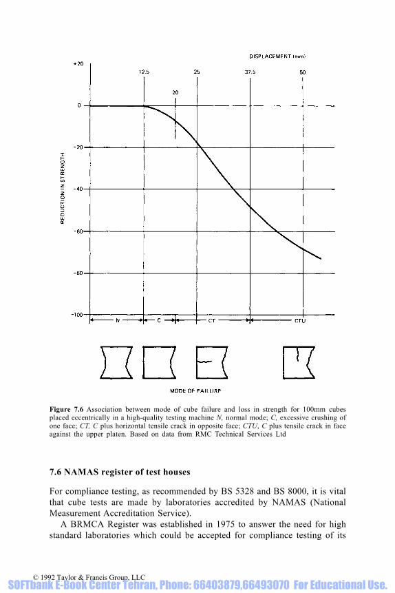
7.6 NAMAS register of test houses
For compliance testing, as recommended by BS 5328 and BS 8000, it is vitalthat cube tests are made by laboratories accredited by NAMAS (NationalMeasurement Accreditation Service).
A BRMCA Register was established in 1975 to answer the need for highstandard laboratories which could be accepted for compliance testing of its
Figure 7.6 Association between mode of cube failure and loss in strength for 100mm cubesplaced eccentrically in a high-quality testing machine N, normal mode; C, excessive crushing ofone face; CT, C plus horizontal tensile crack in opposite face; CTU, C plus tensile crack in faceagainst the upper platen. Based on data from RMC Technical Services Ltd
© 1992 Taylor & Francis Group, LLC SOFTbank E-Book Center Tehran, Phone: 66403879,66493070 For Educational Use.

products by the ready-mixed concrete industry. Before this, the precision oftesting cubes was often erratic and sometimes very poor (Table 7.2), leadingto unnecessary disputes [106, 107].
In 1981 when NATLAS [108] (now NAMAS) was formed withgovernment backing, BRMCA encouraged most of its registered laboratoriesto join [109]. Laboratories are assessed by chartered engineers against therequirements of BS 1881. NAMAS of course covers a much wider field thancube testing, and it is recommended that NAMAS laboratories are used forany other testing.
Figure 7.7 Example of a carbon paper impression made under load to determine the area ofcontact between a cube and an inadequately maintained machine platen
© 1992 Taylor & Francis Group, LLC SOFTbank E-Book Center Tehran, Phone: 66403879,66493070 For Educational Use.

7.7 Interpreting test results for strength
7.7.1 Apparent compliance failures
The first rule for investigating apparent compliance failures is to establish thevalidity of the results and the validity of the compliance failure.
Apparent compliance failures fall into three categories:
(i) Valid failures of compliance(ii) Invalid results associated with testing faults(iii) Valid results below the specified strength which do not fail any
compliance clause.
Results in category (iii) usually only require discussion with the lessexperienced purchaser of the basis of characteristic strength and an explanationof the compliance rules of BS 5328. The more difficult problem is todifferentiate between (i) and (ii) so that appropriate solutions can be found.
7.7.2 Checking on validity
The producer has an obvious duty to assure himself that the results areperfectly valid. Unfortunately, in nine cases out of ten investigation shows theresults to be based on invalid tests. Even more frustrating, often the problemscould have been identified much earlier or possibly prevented altogether (seesimple checks on validity in section 7.3).
Obviously, observation of procedures and equipment may help identifywhether any deviations from standard requirements are now taking place, but
Table 7.2 Summary of results of comparative cube tests for 105 commercial testing authoritiesin 1972. Adapted from Stilwell [110], courtesy of New Civil Engineer. Percentage of laboratories
*Differences of less than 4% were judged not to be statistically significant.
© 1992 Taylor & Francis Group, LLC SOFTbank E-Book Center Tehran, Phone: 66403879,66493070 For Educational Use.

will not necessarily relate to past practice. Sampling and cube-makingcertificates, as required by BS 1881, should be examined. In more complexcases it may be necessary to painstakingly collect data for complex analysis.As an example, curing may be validated by investigating the ratio of 7- to 28-day strength from site data in comparison with the ready-mixed concreteproducer’s control data and cement company data.
If early storage on site has resulted in a loss of moisture or exposure to lowtemperatures, this may have depressed the 7-day strength more than the 28-daystrength such that the ratio of 7-day to 28-day strength is depressed significantly,as shown diagrammatically in Fig. 7.8. In a particular case investigated (see Fig.7.9) it was possible to confirm that there was not only a depression of the 7- to28-day strength ratio but that this depression increased with duration of sitestorage before transfer of cubes to the test laboratory, providing indirect butconclusive confirmation of inattention to site curing.
Examination of cube density data is essential, but it is necessary toremember that depression of cube density can be caused by factors other thaninadequate compaction or an unrepresentative sample, for example (i) lowercement content than intended; (ii) higher water content than intended; or (iii)higher air content than intended (in the case of air-entrained concrete). Eachof these three factors represents a fault in concrete production. Establishingthat none of these has occurred may entail chemical analysis (and microscopicanalysis for entrained-air content) with all the attendant problems ofinterpretation of results. It is more valuable to use cube density and visual
Figure 7.8 Effect of non-standard curing during first few days on strength at 7 and 28 days andon ratio of 7- to 28-day strength (see also Table 7.1)
© 1992 Taylor & Francis Group, LLC SOFTbank E-Book Center Tehran, Phone: 66403879,66493070 For Educational Use.

assessment together as a means of confirming or otherwise the adequacy ofcompaction.
7.7.3 Action relating to valid compliance failures
When valid compliance failures occur, the specifier, in addition to requiringaction to prevent recurrence, has a range of options depending upon theseverity of the failure. These are associated with (i) establishing the strengthof concrete in the structure particularly at key design locations; (ii) forecastingany significant effect on durability; and, depending on the result of theseinvestigations, (iii) deciding on necessity for remedial action.
It is incumbent upon specifiers in law to seek economic solutions, andindeed most specifiers seek to find the quickest and most economic solutionwhich will enable the construction to proceed swiftly, which is usually ineveryone’s interest, including that of the specifier’s own client.
7.7.4 Establishing the strength of concrete in the structure
The purpose of investigating the structure is to identify, in comparison withstructural design requirements, whether or not the in-situ strength is adequatefor the actual loading at the age when it is first to be loaded. If there is somereserve strength not utilized in the structural design or if the low strength hasoccurred at a location of low stress, it may be possible to accept the concrete.
When curing is good and there is adequate time between construction andloading, it may be possible to make allowance for gain in strength between theage of strength assessment and the age of loading. The specifier can call uponthe following for assistance:
Figure 7.9 Example of effect of non-standard site storage of cubes on ratio of 7- to 28-daystrength
© 1992 Taylor & Francis Group, LLC SOFTbank E-Book Center Tehran, Phone: 66403879,66493070 For Educational Use.

(i) BS 6089 (Guide to the assessment of concrete strength in the structure)(ii) Concrete Society Technical Report No. 11, and its addendum on
concrete core testing for strength [111](iii) BS 1881 (Testing of concrete), Part 120, and Parts 200–208 which
advise on the use of core testing, non-destructive testing andinterpretation of results.
It is vital to appreciate that concrete in the structure is likely to have a verydifferent strength from the same concrete in standard cubes, even if tested atthe same age, because of
(i) Differences in curing, particularly at or near surfaces(ii) Differences in compaction(iii) Presence of reinforcement in or near to the concrete sampled(iv) Sedimentation associated with concrete depth(v) Temperature stress and internal movements
Figure 7.10 Illustration of approximate relationship of compressive strengths in the structure andin standard cubes. Redrawn and adapted from BS 6089
© 1992 Taylor & Francis Group, LLC SOFTbank E-Book Center Tehran, Phone: 66403879,66493070 For Educational Use.

and that, in the case of cores, extraction may create a weakness near the cutsurface.
Figure 7.10 shows a typical comparison between cube strength and in-situstrength as provided in BS 6089. The influence of compaction is just as
Table 7.3 Factors to correct in-situ strength forincomplete compaction compared with cubes [111].
Figure 7.11 Effect of curing upon in-situ strength determined after soaking for 2 days in water.Redrawn and adapted from Concrete Society [111]
* Compared with well-made cubes. See BS 1881:Part 120 and [111] for photographs of cut coresurfaces by which assessments of excess voidagemay be made.
© 1992 Taylor & Francis Group, LLC SOFTbank E-Book Center Tehran, Phone: 66403879,66493070 For Educational Use.

important as it was shown to be for cubes. Table 7.3 shows corrections to in-situ strength advocated by the Concrete Society as necessary for differentdegrees of site compaction. The values are compatible with Fig. 7.3 for cubes.The influence of curing is important too, because it is likely to differ from thatadopted for standard cubes, not only at early ages but throughout the life ofthe structure. It is not only possible but highly likely that substantially lowerstrength will occur in the structure by 28 days, compared with cubes, and theremay often be little gain after 28 days, as shown in Fig. 7.11 for average siteconditions. In adverse situations, e.g. unprotected shallow suspended slabs,worse relationships may apply. In favourable situations, e.g. bored piles,strengths comparable with water curing may obtain. Gain in strength with agein structures will depend upon cement characteristics, curing of concrete,carbonation, physical or chemical deterioration and location relative tosurfaces.
The Concrete Society has reported [112] work at BRE with present-daycements which indicates that increases of 10–15 N/mm2, dependent onstrength level, can occur from 28 days to 1 year under continuous watercuring. In air, the gain is reported to be in the order of 5 N/mm2 but some ofthis gain may be associated with surface carbonation and testing cubes in a drycondition. Tested wet to correspond with the testing of cores, the gain may besomewhat smaller.
7.7.5 Interpretation of in-situ cube strength
There are two main ways of interpreting in-situ cube strength data:
(i) Direct comparison with structural design strength(ii) Conversion to estimates of standard cube strength for comparison with
specified cube strength.
The simplest route to follow is (i); (ii) requires agreement of a factor forcompaction, and either acceptance of a global correction factor for typicalcuring or agreement of factors for the effects of age and curing.
For comparison with structural design strength, BS 6089 in effect advisesthat concrete can be accepted if the in-situ strength is at least 0.80×specifiedcharacteristic strength, or proportionally less if the structural design stressunder the actual loading is less than (specified characteristic strength)/1.5,which is the maximum design stress permitted by BS 8110. The ConcreteSociety Technical Report [111] advises a lower value than BS 6089 asacceptable for estimated in-situ cube strength, as follows:
where n is the number of core tests used to determine the mean value.
© 1992 Taylor & Francis Group, LLC SOFTbank E-Book Center Tehran, Phone: 66403879,66493070 For Educational Use.

The difference between the two formulae stems from a difference inpurpose. BS 6089 also takes into account the assessment of old structures fornew purposes, where little is known concerning the structure and where anylongterm gain in strength with age is assumed to be complete. BS 6089 isappropriately more conservative for this application.
Example 1
Specified grade C30Age of cores 35 daysMean in-situ cube strength from 4 cores 25 N/mm2
(a) Minimum acceptable in-situ cube strength 0.80×30(BS6089) =24 N/mm2
Conclusion: concrete can be accepted.
(b) Minimum acceptable estimated in-situ cube strength from CSTR/11 [111]
Conclusion: concrete can be accepted.
Estimation of potential (standard cube) strength may be made to CSTR/11[111] using the following formula, adopting a global factor for curing, an extrafactor being needed for any inadequacy of compaction:
estimated potential strength=1.3×estimated in-situ cube strength
The concrete can be accepted if this estimate is not below the specifiedcharacteristic strength.
Example 2
Data as Example 1, with additional data:
No correction needed for compaction (based on visual assessment and densitytests)Global correction for curing of 1.30 included in the formula is accepted by allparties.
Estimated potential (standard cube) strength from CSTR/11 [111]:
1.30×24=31 N/mm2
Minimum acceptable estimated potential strength
=specified grade=30 N/mm2
Conclusion: concrete can be accepted.
© 1992 Taylor & Francis Group, LLC SOFTbank E-Book Center Tehran, Phone: 66403879,66493070 For Educational Use.

7.7.6 Use of non-destructive testing
Non-destructive test methods—BS 1881, [111], [113]—can be used in lieu ofcore testing or in combination with core testing as described in the previoussection to assess in-situ strength. BS 6089 permits the same formula to be usedas given for core testing.
7.7.7 Remedial work
When assessments of in-situ strength are judged unacceptable, there are anumber of options open to the specifier:
(i) Increasing the strength of the concrete(ii) Strengthening the structure, e.g. by thickening(iii) Redesigning the remainder of the structure to reduce the load on the
weaker elements(iv) Removal and replacement.
Specifiers are usually loath to resort to the last measure because, unless thedefective structure is totally independent of other structures, there may bedifficulties in matching appearance or ensuring structural continuity betweenaccepted and replaced sections of concrete.
Figure 7.12 (Top) Simulation of treatment of a suspended slab. (Bottom) Gains in strength dueto selected accelerating treatments. After Dewar [114]
© 1992 Taylor & Francis Group, LLC SOFTbank E-Book Center Tehran, Phone: 66403879,66493070 For Educational Use.

7.7.8 Increasing the strength and durability of the concrete in the structure
It is often possible to rely on natural gain in strength in well-cured or massconstruction to improve both strength and durability. In other cases it may bepossible to accelerate strength gain, or even to reactivate arrested hydrationand to promote a gain in strength which would otherwise not have occurred,or have occurred only over a number of years. A laboratory study simulatingpractice has confirmed practical observations that significant gains can beobtained [114]. Figure 7.12 illustrates the effect of ponding the top surfacetogether with sealing the under-surface of a 150 mm deep slab, the simulationbeing made with 150 mm cubes.
It is relatively simple, using non-destructive tests, to confirm at selectedpoints that a gain in strength is being achieved and to stop the treatmentwhen sufficient gain has occurred. Both ponding and steam curing have beenused successfully in the UK, and ponding is reported to have been used inAustralia [115].
7.8 Checking mix proportions or quantities
Mix proportions may be checked by producer or purchaser as follows:
(i) Each batch:Observation of batchingRecords of batching (manual or automatic)Analysis of fresh concreteChemical analysis of hardened concreteIndirect checks on water/cement ratio (slump, strength of cubes)Indirect checks on cement content (strength of cubes)
(ii) Overall:As for each batch aboveMaterials stock reconciliation.
7.8.1 Analysis of fresh concrete
Several major problems which have led to only limited adoption of methodsof fresh-concrete analysis include the necessity for skilled operators, theexpense and complexity of tests, sampling inaccuracy, imprecision of the tests,time to obtain a result, and inapplicability to small sites.
A comprehensive BSI draft for development for fresh analysis (DD82)describes several methods in detail and also lays down requirements forassessing precision to ensure maximum accuracy from each method. However,the main difficulty [116] is the introduction of an unknown bias because ofassumptions which cannot be confirmed as true for any given sample. Forexample, physical methods for assessing cement do not discriminate between
© 1992 Taylor & Francis Group, LLC SOFTbank E-Book Center Tehran, Phone: 66403879,66493070 For Educational Use.
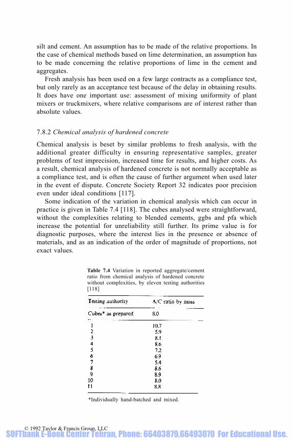
silt and cement. An assumption has to be made of the relative proportions. Inthe case of chemical methods based on lime determination, an assumption hasto be made concerning the relative proportions of lime in the cement andaggregates.
Fresh analysis has been used on a few large contracts as a compliance test,but only rarely as an acceptance test because of the delay in obtaining results.It does have one important use: assessment of mixing uniformity of plantmixers or truckmixers, where relative comparisons are of interest rather thanabsolute values.
7.8.2 Chemical analysis of hardened concrete
Chemical analysis is beset by similar problems to fresh analysis, with theadditional greater difficulty in ensuring representative samples, greaterproblems of test imprecision, increased time for results, and higher costs. Asa result, chemical analysis of hardened concrete is not normally acceptable asa compliance test, and is often the cause of further argument when used laterin the event of dispute. Concrete Society Report 32 indicates poor precisioneven under ideal conditions [117].
Some indication of the variation in chemical analysis which can occur inpractice is given in Table 7.4 [118]. The cubes analysed were straightforward,without the complexities relating to blended cements, ggbs and pfa whichincrease the potential for unreliability still further. Its prime value is fordiagnostic purposes, where the interest lies in the presence or absence ofmaterials, and as an indication of the order of magnitude of proportions, notexact values.
Table 7.4 Variation in reported aggregate/cementratio from chemical analysis of hardened concretewithout complexities, by eleven testing authorities[118]
*Individually hand-batched and mixed.
© 1992 Taylor & Francis Group, LLC SOFTbank E-Book Center Tehran, Phone: 66403879,66493070 For Educational Use.
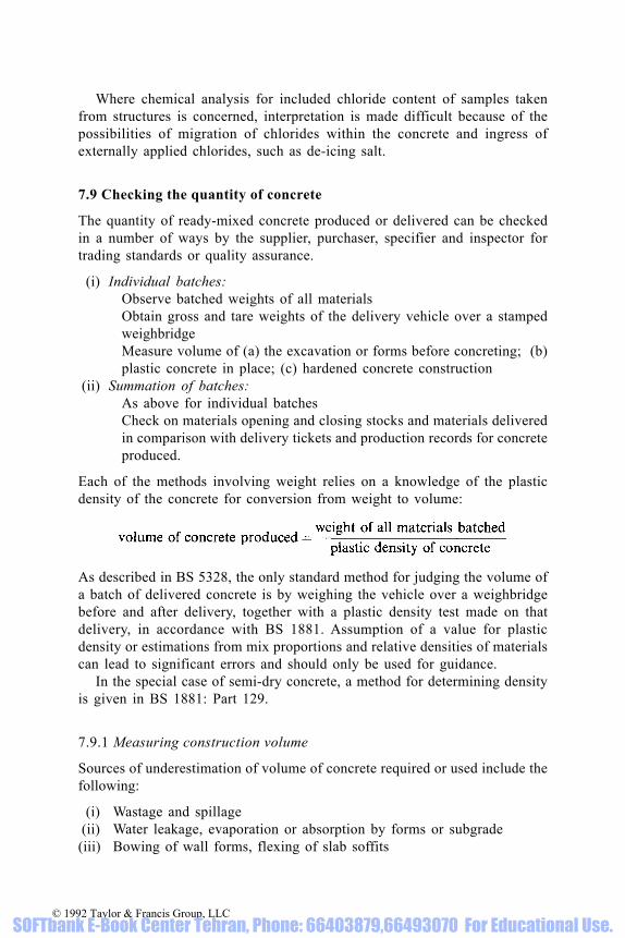
Where chemical analysis for included chloride content of samples takenfrom structures is concerned, interpretation is made difficult because of thepossibilities of migration of chlorides within the concrete and ingress ofexternally applied chlorides, such as de-icing salt.
7.9 Checking the quantity of concrete
The quantity of ready-mixed concrete produced or delivered can be checkedin a number of ways by the supplier, purchaser, specifier and inspector fortrading standards or quality assurance.
(i) Individual batches:Observe batched weights of all materialsObtain gross and tare weights of the delivery vehicle over a stampedweighbridgeMeasure volume of (a) the excavation or forms before concreting; (b)plastic concrete in place; (c) hardened concrete construction
(ii) Summation of batches:As above for individual batchesCheck on materials opening and closing stocks and materials deliveredin comparison with delivery tickets and production records for concreteproduced.
Each of the methods involving weight relies on a knowledge of the plasticdensity of the concrete for conversion from weight to volume:
As described in BS 5328, the only standard method for judging the volume ofa batch of delivered concrete is by weighing the vehicle over a weighbridgebefore and after delivery, together with a plastic density test made on thatdelivery, in accordance with BS 1881. Assumption of a value for plasticdensity or estimations from mix proportions and relative densities of materialscan lead to significant errors and should only be used for guidance.
In the special case of semi-dry concrete, a method for determining densityis given in BS 1881: Part 129.
7.9.1 Measuring construction volume
Sources of underestimation of volume of concrete required or used include thefollowing:
(i) Wastage and spillage(ii) Water leakage, evaporation or absorption by forms or subgrade(iii) Bowing of wall forms, flexing of slab soffits
© 1992 Taylor & Francis Group, LLC SOFTbank E-Book Center Tehran, Phone: 66403879,66493070 For Educational Use.

(iv) Filling of gaps(v) Over-excavation
(vi) Unevenness of subgrade.
7.9.2 Measuring volume to be concreted
Direct volume measurement may be satisfactory, provided account is taken ofthe sources of error given above, and a check is made after concreting toconfirm that the final top surface level does not differ from that assumed andthe forms have not moved. For example, if the centre of a 150mm slabdeflected downwards by 5 mm during concreting but the upper surface waslaid level, an increased volume of 3% would be required at the centre,decreasing towards the edges. In fact, the centre is more commonly cast proudrelative to the edges, which would increase the volume required still further.
Reliance should not be placed on construction drawings—all measurementsshould be made on site. The volume of concrete in bored piles, particularlythose where the pile is withdrawn, can often be underestimated because ofoversize excavation.
7.9.3 Measuring volume of plastic concrete after finishing
This method is useful for paving or slabs, provided depth is measured atsufficient points over the area concreted to enable an accurate average depthto be measured.
7.9.4 Measuring volume of hardened concrete
This can be an accurate method provided all significant dimensions can bemeasured. The most difficult problem is the concrete slab, where the undersideis inaccessible. No reliance should ever be placed upon measurements madeat the edges alone, because the edge cannot be guaranteed to be representativeof the depth elsewhere. Sets of levels of the base before concreting and the topsurface after hardening are to be preferred, but again, the sources of errorsindicated earlier need to be considered.
In certain cases, holes may be permitted to be drilled to obtain directmeasurements of depth. There are methods of non-destructive testing whichenable depth of slabs to be measured, but it is important for calibrations to beconfirmed by making some test drillings for direct depth measurement.
7.10 Variation in density and yield
It is important to establish relationships between plastic density and mix (i.e.cement content) to ensure correct batch weights for each cubic metre of
© 1992 Taylor & Francis Group, LLC SOFTbank E-Book Center Tehran, Phone: 66403879,66493070 For Educational Use.

concrete, for each type of concrete and set of materials in use. Normalvariations with properties of materials do not have a significant influence oneither density or yield. However, it is important to take account of variationsin entrained air content and in density of lightweight aggregates which maysignificantly affect concrete density and yield.
© 1992 Taylor & Francis Group, LLC SOFTbank E-Book Center Tehran, Phone: 66403879,66493070 For Educational Use.

Part 2
PRACTICE
© 1992 Taylor & Francis Group, LLC SOFTbank E-Book Center Tehran, Phone: 66403879,66493070 For Educational Use.

8 Production, delivery and qualityassurance
8.1 Production methods [119]
Ready-mixed concrete is produced in the UK using many differentcombinations of each of the elements of the process: handling the incomingmaterials; batching the constituents; mixing the concrete; loading the deliveryvehicles. The industry has not settled on a ‘best way’, and choice has beenbased on economics related to perceived markets for each particular plant. Asthe shelf life of the product is so short, the production units (the plants) havehad to be located convenient to potential markets.
To design a plant to produce ready-mixed concrete necessitates havingrealistic assessment of the likely size of the market and the types of concreteused locally, as well as:
(i) Types of materials(ii) Storage capacity
(iii) Processing sequences(iv) Truckmixer capacity and throughput(v) Planning requirements
(vi) Quality control requirements(vii) Regulatory requirements(viii) Duration of operation(ix) Health and safety regulations.
8.1.1 Material types
The different types of cements for which provision has to be made will dependupon the types of concrete likely to be required in the market area, whereasthe types of aggregates will be related to what is readily available: gravel,land-borne or marine; limestone; granite; sand; crushed rock fines. It is normalpractice to stock 20 mm and 10 mm maximum-size coarse aggregate, and also40 mm, depending upon local practice.
A twin-silo plant that stocks pc and ggbs or pfa will be able to produceordinary concrete and some grades of sulphate-resisting concrete, but not, forexample, rapid-hardening concrete, for which a silo would need to be emptiedand restocked with rapid-hardening cement.
© 1992 Taylor & Francis Group, LLC SOFTbank E-Book Center Tehran, Phone: 66403879,66493070 For Educational Use.

8.1.2 Storage capacity
Handling incoming materials in bulk is fundamental to the economicproduction of ready-mixed concrete. The current legal weight limit onvehicles, based on the 10-tonnes maximum axle load, is a major factorinfluencing the delivery costs of cements and aggregates. Currently, cementtankers deliver up to 20 tonnes of cement and, when concrete productiondemand rises, the ready-mixed concrete producer relies on the cement maker’stanker fleet to keep the silos stocked, although changes in cement pricing havemeant that it can be advantageous for the ready-mixed concrete company tocollect the cement ex-works. Modern tippers carry up to 24 tonnes ofaggregates. The design of the storage elements, cement silos and aggregatestorage bins is obviously influenced by the bulk delivery vehicle capacity.Where plants are situated next to sources of aggregate supply, such asquarries, gravel pits, railheads or wharves, then storage facilities for theaggregates at the ready-mixed concrete plants do not need to be so large.Stabilizing the moisture content of the aggregate, particularly the sand, can bean important factor in determining the aggregate storage capacity and layout.
8.1.3 Processing sequence
A plant may be designed for (i) batching; (ii) batching and mixing; or (iii)batching, with a mixing option. The maximum batch size is a major factor indetermining the rate of production of a plant, but few plants are designed toload a truckmixer with materials in a single batch.
The accurate weighing of solid constituent materials has been afundamental requirement for producing quality concrete for many years, butthe degree of automation built into the batching process has only in recentyears shown a marked increase. The reliability of automatic controls hasimproved and computerization has enabled more sophisticated adjustments tobe incorporated. The commonest weighing equipment continues to be thebalanced mechanical lever system, although load cell weighing is used. Somecontinuous weighing systems are still in use. Controlling the discharge fromstorage and weigh hopper (Fig. 8.1) is in the main through gates operated bycompressed air cylinders.
With increasing emphasis on calibration, there is a need to be able to carryout the regulatory routine and specialist checks of the weighing processwithout too much difficulty, and this is having its influence on plant layouts.The use of flow meters for water measurements almost universal, although insome plants the water is weighed. The use of dispensers to measure admixturesis almost universal. Again the need to be able to calibrate them easily is havingan influence on their design and installation.
Because modern truckmixers are able to thoroughly mix a wide range ofconcrete mixes, the justification for including a mixer in the processing
© 1992 Taylor & Francis Group, LLC SOFTbank E-Book Center Tehran, Phone: 66403879,66493070 For Educational Use.

sequence is often influenced by the local market demand for lean mixconcretes. These semi-dry concretes are frequently collected in tippers, and soa mixer has to be included in the plant design.
In general, plants in which all the concrete has to be processed through themixer are only situated in urban locations. A compromise is to have twoproduction streams, with a ‘dry-leg’ going straight into the truckmixer and a‘wet-leg’ going through a mixer. Such ‘wet-leg’ mixers are usually of limitedcapacity.
As well as adding to the capital costs a mixer will certainly increase theenergy requirements of a plant and the maintenance costs, so the decisionwhether or not to include or omit a mixer in the production process can be avital one in determining its commercial viability.
In the UK the most common method of producing ready-mixed concrete isto load the batched materials into a truckmixer, mixing them together byrotating the drum. The most important factor in determining within-batchuniformity is the method used to charge the mixer. Practices have evolved tosuit the characteristics of the local materials, but if concrete is not well mixedthe first thing to examine is the loading sequence and the procedures used toadd water. The options available for loading a mixer are:
(i) Ribbon loading(ii) Cement-last loading
(iii) Sandwich loading(iv) Slurry mixing(v) Single batching
(vi) Multiple batching.
As well as seeking uniformity of the mix, the loading sequence must be such as
Figure 8.1 Weigh hopper system. Redrawn and adapted from Crowther [144]
© 1992 Taylor & Francis Group, LLC SOFTbank E-Book Center Tehran, Phone: 66403879,66493070 For Educational Use.
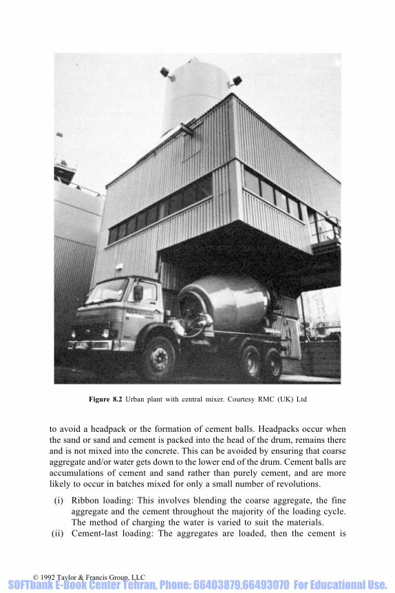
to avoid a headpack or the formation of cement balls. Headpacks occur whenthe sand or sand and cement is packed into the head of the drum, remains thereand is not mixed into the concrete. This can be avoided by ensuring that coarseaggregate and/or water gets down to the lower end of the drum. Cement balls areaccumulations of cement and sand rather than purely cement, and are morelikely to occur in batches mixed for only a small number of revolutions.
(i) Ribbon loading: This involves blending the coarse aggregate, the fineaggregate and the cement throughout the majority of the loading cycle.The method of charging the water is varied to suit the materials.
(ii) Cement-last loading: The aggregates are loaded, then the cement is
Figure 8.2 Urban plant with central mixer. Courtesy RMC (UK) Ltd
© 1992 Taylor & Francis Group, LLC SOFTbank E-Book Center Tehran, Phone: 66403879,66493070 For Educational Use.

added. If the cement is added without turning the truckmixer drum andmixing water is not added nor mixing done until arrival at the site, thenvery little cement becomes wetted. This can be advantageous when theconcrete has to be transported long distances.
(iii) Sandwich loading: In this loading the cement is sandwiched betweenequal increments of ribboned aggregates and water.
(iv) Slurry mixing: Water is loaded first followed by the cement and a slurryformed for a short period before the aggregates are ribbon loaded.
(v) Single batching: All the materials for one load are batched and loadedin one cycle.
(vi) Multiple batching: The materials for a load are batched in two or morecycles dependent upon the capacity of the weighing systems.
8.1.4 Truckmixer capacity and throughput (see 10.1)
The number of truckmixers operating from a plant is usually the critical factorin determining the throughput, and has to take into account both truckmixercapacity and radius of operations. The average number of truckmixersoperating from plants in the UK is three and the average radius of operationsis 8 km. When the demand for concrete is high, the number of truckmixers isincreased, and when demand is low, sales are sought further away from theplant.
Figure 8.3 Low-level batching plant with truckmixer. Courtesy Redland Readymix Ltd
© 1992 Taylor & Francis Group, LLC SOFTbank E-Book Center Tehran, Phone: 66403879,66493070 For Educational Use.

8.1.5 Planning requirements
The requirements of planning authorities for the approval of sites for ready-mixed concrete plants vary, dependent upon the location. Environmentalconditions are different in a quarry from those pertaining in an urban industrialestate, but producers have to meet the requirements of the EnvironmentalProtection Act and the discharge requirements of the National RiversAuthority (NRA).
8.1.6 Quality control requirements
The proliferation of methods currently being used to specify concrete meansthat a responsible ready-mixed concrete producer who wishes to meet allmarket demands must have a very comprehensive quality system. Therequirements for sampling, making cube specimens, curing and testing themunder standard conditions involves the setting up of a laboratory where the testdata can be collated and new mixes designed. The cost of quality controlfacilities has encouraged the grouping of plants within a company into areas,with the quality control being managed from one technical centre. Thelaboratory and mobile sampling and testing facilities and staffing, needed tomonitor the constituent materials and to ensure that mixes supplied complywith the orders received, form a key part of any company’s quality system, andthe cost of setting up a laboratory and control system is a major item.
8.1.7 Regulatory requirements
British Standards lay down basic standards covering the production processwhich have to be met:
BS 1305: Batch type concrete mixersBS 1881: Testing concreteBS 5328: Concrete
Since the 1950s trade practice has evolved its own requirements coveringproduction and delivery of ready-mixed concrete, to ensure that:
(i) Each plant has efficient equipment provided and well maintained toensure the capability to produce and deliver a range of concrete mixesto the standards specified in BS 5328 in respect of quality and quantity
(ii) Methods of material storage and handling, and concrete production anddelivery are used which minimize the risks of non-compliance of theproduct in terms of quantity and quality.
The current requirements for good practice are set out in the TechnicalRegulations of the Quality Systems for Concrete, published by QSRMC, withwhich all members of the Scheme have to comply.
© 1992 Taylor & Francis Group, LLC SOFTbank E-Book Center Tehran, Phone: 66403879,66493070 For Educational Use.

8.1.8 Duration of operations
The estimated time a plant is to be in operation is a critical factor in determiningthe type of plant to be installed. Few plants are truly mobile, but transportableplants are quite common, and many ready-mixed concrete producers now set upplants on major construction sites for the duration of the job. Whatever theperiod of time for which the plant is to be used, considerable expenditure onfoundations, services, erection and dismantling, access roads and paved areas,wash-downs and effluent disposal will be required. No matter how relativelyshort the time a plant is to be in operation, the product has to be of the correctquality, so the standards of good practice remain the same.
8.1.9 Health and safety
For ready-mixed concrete plants the Health and Safety Executive haverecommended that particular attention needs to be paid to the following:
(i) Conveyor guarding: Adequate guards on conveyors and conveyordrives; positioning of the bottom pulley to facilitate clearing of spillage,safe access for correction of tracking and adjustment of belts when inmotion
(ii) Access to mixers: Interlocking of access points on mixers, so as to avoidhand and arm injuries
(iii) Emergency stops and lockout procedures: Sensible positioning of beltisolators: system of lockouts for ensuring that plant is isolated from thepower supply when guards have to be removed for maintenance
(iv) Traffic control: Routeing of incoming cement tankers, aggregate tippersand outgoing truckmixers to minimize reversing; ensuring that vehiclesand pedestrians are separated; use of audible warning systems
(v) Inspection points: Provision of grids and pulpits at ground hoppertipping points
(vi) Inspection system: Providing a safe system for the fresh concrete to bevisually checked during mixing
(vii) Safe access: Provision of edge protection and safe access to all parts ofthe plant for maintenance as well as operating staff
(viii) Silos and tanks: Provision of safe entry into silos and tanks; provisionof relevent safety equipment, including lighting and anchorages
(ix) Security: Security on the site against access by members of the public.
8.2 Organizing production and delivery
Organization within companies, for operating and controlling production andscheduling deliveries to sites, varies from company to company. Somecompanies’ operations are controlled at depot level, whereas a number of thelarger and medium-sized companies have centralized shipping offices covering
© 1992 Taylor & Francis Group, LLC SOFTbank E-Book Center Tehran, Phone: 66403879,66493070 For Educational Use.

particular markets (Fig. 8.4). Whilst the requirements lend themselves tocomputerization, the economics are influenced by geography and marketconditions. Part of any company’s organization is a very strict credit controlsystem, made necessary by the short period between enquiry/order anddelivery, and the inability to reclaim the delivered products.
Management systems have been developed using computers to improveproductivity levels. The extent of computerization [120] has varied between
Figure 8.4 Central shipping office. Courtesy C & G Concrete Ltd
© 1992 Taylor & Francis Group, LLC SOFTbank E-Book Center Tehran, Phone: 66403879,66493070 For Educational Use.

Figure 8.5 A basic batch card
© 1992 Taylor & Francis Group, LLC SOFTbank E-Book Center Tehran, Phone: 66403879,66493070 For Educational Use.

companies, from virtually complete computerization of every function, to theuse of small personal computers for individual element, e.g. batchinginstructions print-out in place of manually prepared batch-books. An exampleof a basic batch card is given in Figure 8.5.
Complete software and hardware packages are available [121] covering:
(i) Accepting orders from customers(ii) Executing deliveries to customers including batch/mix control(iii) Scheduling constituent materials to plants(iv) Administration and invoicing.
8.3 Delivery
8.3.1 Truckmixers [122]
Ready-mixed concrete is not only a product, it is a service, and each year about20 million cubic metres of concrete are delivered in truckmixers [118]. Thetruckmixer has developed since the late 1940s from a mobile site mixer into aspecialized vehicle capable of mixing, delivering and distributing concrete in avery economic manner. Indeed, in the viability of ready-mixed concretedepends on the efficient utilization of the specialized truckmixer fleet.
8.3.1.1 Mixing. The versatile truckmixer can function in the productionprocess in three basic ways. (i) As a mixer at a ready-mixed concrete plant:the truckmixer is loaded with the dry batched materials together with waterand mixing is completed at the plant. During transit, the drum can be revolvedslowly to keep the mix agitated. On arrival at site, the drum is rotated atmixing speed for a few minutes to ensure complete remixing, before discharge.(ii) As a mixer at the site: the truckmixer is loaded with the dry batchedmaterials at the plant, which are then transported to the site. On arrival, mixingwater is added and the mixing completed before discharge. (iii) As an agitator:the truckmixer is loaded with mixed concrete from a mixer at the plant. Duringtransit the drum can be revolved slowly to keep the mix agitated and at sitethe drum is revolved at mixing speed to ensure complete remixing beforedischarge.
8.3.1.2 Delivery. Although truckmixer vehicles available in the UK range from2 to 9 cubic metres capacity, the majority in use have a load capacity of 6cubic metres of concrete (Fig. 8.6). With a ‘shelf life’ of only a few hours,ready-mixed concrete is very much a ‘local delivery’ service, the averagedistance from the depot to point of delivery being about 8 km, varyingbetween town and country. Long deliveries are possible, but the economicsneed careful scrutiny.
8.3.1.3 Distribution. On arrival at the site, the standard truckmixer can:
© 1992 Taylor & Francis Group, LLC SOFTbank E-Book Center Tehran, Phone: 66403879,66493070 For Educational Use.

(i) Mix the concrete and, with measured water addition, adjust thecharacteristics of the plastic concrete
(ii) Using a fitted chute and extensions, discharge the concrete direct(iii) Control the rate of discharge to suit the placing requirements on site. 8.3.1.4 Type of vehicles. The mixer unit, mounted on a commercial vehiclechassis, consists of an abrasion-resistant steel drum inclined at about 16°.There are blades inside the drum to mix and agitate the ingredients when thedrum is rotated in one direction, and to discharge the mixed concrete when thedrum is reversed. The power for turning the drum can come from the maintruck engine, using a hydraulic power drive to the drum; a separate (donkey)
Figure 8.6 A 6 cubic metre truckmixer. Courtesy Ritemixer
© 1992 Taylor & Francis Group, LLC SOFTbank E-Book Center Tehran, Phone: 66403879,66493070 For Educational Use.
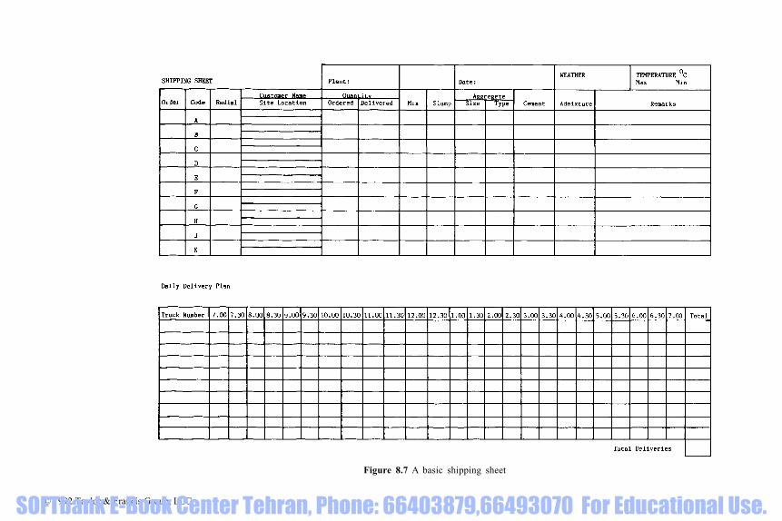
Figure 8.7 A basic shipping sheet
© 1992 Taylor & Francis Group, LLC SOFTbank E-Book Center Tehran, Phone: 66403879,66493070 For Educational Use.

engine, with hydraulic drive; or a separate engine with a mechanical couplingto the drum. The cost of a complete unit (chassis, cab and mixer unit) is about£56000 (1991 prices). It is possible to change the drum when it gets worn, therate of wear being very dependent upon the abrasive effects of the aggregates,but most companies operate on a life of over four years for the mixer.
There are three major producers of truck-mounted mixer units in the UK,but manufacturers from other countries are also selling units in the UK.
8.3.1.5 Methods of operation. The average number of truckmixers operatingout of one depot in the UK is three. However, trucks can easily be moved fromone depot to another to meet peak demands. The average number of deliveriesmade by a truckmixer is five per day. Where a company has a group of depotsin an area, rather than allow each individual depot to control its vehicles,‘central shipping’ has been found to lead to higher utilization of the trucks. Anexample of a basic shipping sheet is given in Fig. 8.7. Various sizes oftruckmixers in a fleet can assist in economic scheduling of deliveries but in themain it is usual to standardize on one size.
There are about 3000 truckmixers operating in the UK. The majority ofthese trucks are operated by ‘owner-drivers’. The owner-drivers are notcompany employees, but are contractors with exclusive contracts to carry onecompany’s product on a hire or reward basis. There is a close contractual andfinancial relationship between the driver and the company. The truck chassisis either purchased or leased by the driver, but the mixer unit normally remainsthe property of the company.
Some ready-mixed concrete companies own truckmixers and employ‘company’ drivers either exclusively or alongside ‘owner-drivers’.
8.3.1.6 Regulations. Each driver of a standard truckmixer has to hold an HGVClass II Licence. If he is an owner-driver he also has to hold a Certificate ofProfessional Competence or be exempt from its requirements before he canobtain a Standard Operator’s Licence. The taxation and insurance costs of atruckmixer are currently about £3000 a year.
8.3.1.7 Why a specialized vehicle? The justifications for a specialized vehiclefor delivering concrete are that it can:
(i) Safely convey a whole range of concrete mixes(ii) Agitate the mix in the time between mixing and discharging(iii) Allow the concrete workability to be adjusted, by adding water if
necessary(iv) Distribute the concrete by driving on and around the site and by means
of an extended chute control the height and radius of discharge.
Non-agitating vehicles can be used to deliver mixed concrete that is not proneto segregation.
© 1992 Taylor & Francis Group, LLC SOFTbank E-Book Center Tehran, Phone: 66403879,66493070 For Educational Use.
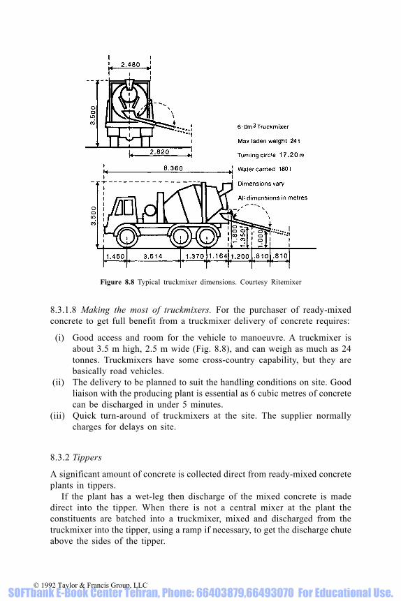
8.3.1.8 Making the most of truckmixers. For the purchaser of ready-mixedconcrete to get full benefit from a truckmixer delivery of concrete requires:
(i) Good access and room for the vehicle to manoeuvre. A truckmixer isabout 3.5 m high, 2.5 m wide (Fig. 8.8), and can weigh as much as 24tonnes. Truckmixers have some cross-country capability, but they arebasically road vehicles.
(ii) The delivery to be planned to suit the handling conditions on site. Goodliaison with the producing plant is essential as 6 cubic metres of concretecan be discharged in under 5 minutes.
(iii) Quick turn-around of truckmixers at the site. The supplier normallycharges for delays on site.
8.3.2 Tippers
A significant amount of concrete is collected direct from ready-mixed concreteplants in tippers.
If the plant has a wet-leg then discharge of the mixed concrete is madedirect into the tipper. When there is not a central mixer at the plant theconstituents are batched into a truckmixer, mixed and discharged from thetruckmixer into the tipper, using a ramp if necessary, to get the discharge chuteabove the sides of the tipper.
Figure 8.8 Typical truckmixer dimensions. Courtesy Ritemixer
© 1992 Taylor & Francis Group, LLC SOFTbank E-Book Center Tehran, Phone: 66403879,66493070 For Educational Use.

Figure 8.9 Application of a belt conveyor. Courtesy BRMCA
© 1992 Taylor & Francis Group, LLC SOFTbank E-Book Center Tehran, Phone: 66403879,66493070 For Educational Use.

8.3.3 Conveyors
A few truckmixers have conveyors [123] attached to them (Fig. 8.10). Theapplications of a belt conveyor are shown in Fig. 8.9. A second truckmixer canbe used to feed the conveyor.
8.4 Quality assurance
To have assurance about the qualities of concrete requires that:
(i) The qualities required of the fresh and hardened concrete are objectivelydefined
(ii) The production delivery and site processes are carried out undercontrolled conditions which allow the whole process to be able to betraced from the constituent materials right through to the cured concrete
(iii) All testing carried out in the control and compliance testing is valid.
Ready-mixed concrete production and delivery is only part of the QA process,but if the concrete is produced under conditions complying with BS 5750(Quality systems) and BS 5328 (Concrete), then the degree of assurance isincreased.
Figure 8.10 Conveyor mounted on a truckmixer. Courtesy Tarmac Topmix Ltd
© 1992 Taylor & Francis Group, LLC SOFTbank E-Book Center Tehran, Phone: 66403879,66493070 For Educational Use.

The ready-mixed concrete producer can only supply what is ordered,because the contract to supply only exists between the purchaser and supplier,so that the ready-mixed concrete producer is dependent upon the interpretationof the specification by the person who eventually orders the concrete.
The concrete producer completes his part of the contract having producedthe concrete and delivered it down the discharge chute. He has no control overhow the concrete is placed, compacted, finished, cured or protected.Production control testing by the ready-mixed concrete producer is required tobe in accordance with the agreed standards. Unless the compliance testingcarried out by the purchaser is in accordance with the same agreed standardsit is of limited value.
Quality assurance covers the whole process, not just the production, buthaving assurance on the quality of the production process is a major element(see 10.3.3).
© 1992 Taylor & Francis Group, LLC SOFTbank E-Book Center Tehran, Phone: 66403879,66493070 For Educational Use.

9 Specifications and supervision
9.1 Interpreting specifications
The specification is a means of communicating the requirements of thedesigner to those involved in turning the design into reality. It should be adefinition of the quality the designer requires and is willing to pay for. To getthe required quality, it is essential that it is not open to differentinterpretations; in other words it is objective, rather than subjective.
9.1.1 Uses of concrete specifications
In the construction process the specification for concrete, as a material, is subjectedto scrutiny by numerous people carrying out widely differing activities, each puttingemphasis on different parts of the specification and tending to interpret therequirements to the benefit of the interests they represent (Fig. 9.1)
Activity InterpretationDesigning the structure Deciding the qualities required of concrete in its
finished hardened state and incorporating them in aspecification.
Billing Scheduling the different qualities individuallydescribed in the specification and drawings etc, andtaken-off volumes of each.
Estimating (1) Interpreting the different qualities individuallydescribed in the bill and any qualities additionallyrequired by the construction process, the volumes ofeach and translating them into enquiries.
Quoting Interpreting the qualities described in the enquiry (andthe overall requirements of the specification, if it hasbeen provided with the enquiry) and cheaperalternatives available, which still comply with thespecification as given in the enquiry.
Estimating (2) Pricing the concrete as described in the specification/enquiry/quotation.
Buying Purchasing the concrete as scheduled in theprogramme (at the best price).
(Contd.)
© 1992 Taylor & Francis Group, LLC SOFTbank E-Book Center Tehran, Phone: 66403879,66493070 For Educational Use.

Figure 9.1 Interpreting the specification
© 1992 Taylor & Francis Group, LLC SOFTbank E-Book Center Tehran, Phone: 66403879,66493070 For Educational Use.

Activity InterpretationDesigning the mixes Selecting the materials and designing the concrete
mix that will meet the purchaser’s agreed qualityrequirements, based on existing data.
Producing the mixes Mixing the constituent materials in the correctproportions to meet the mix design criteria.
Ordering Placing the order for the concrete as agreed betweenthe purchaser and supplier
Delivery Transporting the mixed concrete to site and ensuringthat the properties of the fresh concrete are asagreed with the purchaser are met.
Controlling the quality Testing the mixed concrete to ensure that it meetsthe mix design criteria and taking action to ensurethat it continues to do so.
Compliance testing Testing the mixed concrete to ensure that it meetsthe specified quality requirements.
Placing and compacting Applying skilled workmanship to the fresh concreteto ensure it will meet the specified qualities in thehardened state in the construction.
Curing and protecting Applying practical workmanship to ensure that thenewly hardened concrete will meet the specifiedquality requirements in the fully hardened state inthe structure.
At each activity the wording changes and it is so easy for the potential endquality to change dramatically, depending upon the interpretation and theaction taken.
9.1.1.1 Designing the structure. The very versatility of concrete makes it anideal material to solve a wide variety of construction design problems, butcare needs to be taken, starting at the design stage, to avoid a few problemsthat can occur if it is badly specified or misused. It is essential to keep anyproblems and their solutions, in perspective (Fig. 9.2). Whilst the totalsolutions to these problems may be highly complex at the design andspecification writing stage, a simplistic approach can frequently achieve morethan including a treatise on concrete technology in the specification. Tables9.1, 9.2 and 9.3 provide information on precautions against sulphate, acid andfreeze/thaw attack respectively.
(i) Sulphate attack: To combat sulphate attack ensure that the concreteelement is substantial enough, the mix is of an adequate grade to provideimpermeable concrete and the cement used has sulphate-resistingcharacteristics: this requires knowledge of soil and groundwater sulphateconditions at the design stage (see 1.2.7).
© 1992 Taylor & Francis Group, LLC SOFTbank E-Book Center Tehran, Phone: 66403879,66493070 For Educational Use.

(ii) Freeze/thaw: entraining air in a concrete of correct grade. If the work islikely to be carried out in cold weather, ensure that adequate facilitiesfor ‘winter concreting’ are billed (see 1.3.4.).
(iii) Abrasion resistance: specifying a high grade of concrete is an importantfactor in ensuring an abrasion-resistant concrete, but it needs to be fullycompacted and properly cured to develop its potential. (See BS 8110,Tables 3.2, 3.4, Clause 6.5 and Section 6.6).
(iv) Structural cracking: detailing the joints, ensuring enough reinforcementand that an appropriate grade of concrete is fully compacted andproperly cured, will minimize the risk of structural cracking. Adequatetime should be allowed for before striking the formwork (see 3.2)
(v) Corrosion of reinforcement: Design and detailing should provide foradequate cover to the steel, but it is essential to ensure that it is achievedon site. Cover needs to be physically checked before the concrete ispoured, and with a cover-meter after the concrete is cast. If there are likelyto be difficulties in achieving the cover required, specify a higher grade ofconcrete. If there are likely to be difficulties in compacting the concretearound the steel, specify high workability. Specifying the correct nominalsize of aggregate to suit the cover is also important (see 3.4).
Figure 9.2 Durability in perspective
© 1992 Taylor & Francis Group, LLC SOFTbank E-Book Center Tehran, Phone: 66403879,66493070 For Educational Use.

Table 9.1 Precautions against sulphate attack (see also Table 1.15)
Notes:(1) This table is based on Table 7 of BS 5328: Part 1:1991(2) Inclusive of content of pfa or ggbs. These cement contents relate to 20 mm nominal
maximum size aggregate. In order to maintain the cement content of the mortar fraction atsimilar values, the minimum cement contents given should be increased by 50 kg/m3 for 10mm nominal size aggregate and may be decreased by 40 kg/m3 for 40 mm nominalmaximum size aggregate
(3) When using the strip foundations and trench fill for low-rise buildings to Class 1 sulphateconditions further relaxation to 220 kg/m3 in the cement content for C 20 grade concrete ispermissible
(4) Ground granulated blastfurnace slag to BS 6699(5) Pulverized fuel ash to BS 3892: Part 1:1982(6) BRE Digest 363, July 1991 permits ggbs and pfa blends to meet Class 4 condition© 1992 Taylor & Francis Group, LLC
SOFTbank E-Book Center Tehran, Phone: 66403879,66493070 For Educational Use.

Table 9.2 Precautions against acid attack
Notes:(1) This table is based on Tables 3.2 and 6.2 of BS 8110 Part 1:1985. For alternative recommendations see also BRE Digest 363.(2) Applicable only to air-entrained concrete.(3) Unprotected Portland cement concrete should not be used in persistent acid conditions of pH 5.5 or less.(4) Inclusive of ggbs or pfa content.
© 1992 Taylor & Francis Group, LLC SOFTbank E-Book Center Tehran, Phone: 66403879,66493070 For Educational Use.

(vi) Alkali-silica reaction: the maximum alkali level of the concrete or analternative route permitted in accordance with the Concrete Societyreport should be specified (see 1.2.8)
(vii) Non-structural cracking: to minimize non-structural cracking requires acohesive mix which can be readily compacted around the reinforcement.However, the main requirement is proper and sustained curing, whichrequires strict and continuous supervision (see 3.2).
9.1.1.2 Specifying the concrete. An integral part of the design process isspecifying the concrete to ensure that the qualities assumed in the design areincorporated in the construction. Guidance on aligning various mixcharacteristics to grades is given in section 4.6.1.
Determining the type of mix to be specified is an important decision to bemade at the specifying stage. Designated mixes are quality assured designedmixes linked to particular applications (see 9.2.3.). The characteristics ofdesignated mixes are set out in Table A.1 and typical applications are givenin Table A.4. The mix design and control of all the appropriate mixcharacteristics, not just strength, are audited as part of the QA procedures.Designed mixes have been the commonest mixes in use and enable the ready-mixed concrete producer to apply his expertise to best meet the specifiedrequirements with the materials to be used. Prescribed mixes need only beused for very special applications, for example when a particular type ofexposed aggregate finish is to be produced. Standard mixes may be relevantfor specifying small quantities of site-mixed concrete, but are not normallyappropriate for ready-mixed concrete. Details of standard mixes are given inBS 5328: Part 2 Section 4 and some typical applications are included inTable A.4.
To be assured of the required quality of concrete as a material, it isimportant that before billing, the following decisions are made:
Table 9.3 Precautions against freeze/thaw attack.
Notes:(1) This table is based on Clause 4.3.3 of BS 5328:
Part 1:1991(2) It is applicable to concretes of grade C50 and
below.
© 1992 Taylor & Francis Group, LLC SOFTbank E-Book Center Tehran, Phone: 66403879,66493070 For Educational Use.

(i) What grade(s), based on design parameters and site conditions(ii) What cements, based on site service conditions(iii) What aggregate size, based on structural section(iv) Which admixtures, based on site conditions(v) What compliance rules, based on BS 5328: Part 4 and BS 1881.
9.1.1.3 Billing. The scheduling of the various qualities of concrete can raisequestions that only those involved in the design can answer, so it is importantto appreciate, at the billing stage, the factors that can affect the pricing andhave engineering judgements made before commercial decisions are taken.The type of cement is usually the most important cost factor, so it is essentialto bill, for example, sulphate-resisting concrete separately to normal concrete.The price difference can be quite considerable, unless ggbs or pfa arepermitted as an alternative. Similarly, air-entrained concrete can be differentin price from plain concrete of the same grade, and concrete of highworkability costs more to produce than concrete of the same grade withmedium workability. The specifier should not normally need to state theworkability. The constructor should be allowed to select the workability to suitthe site conditions.
9.1.1.4 Estimating (1). At the time of preparing an estimate, recognition of thedifferent qualities of concrete required by the design is necessary, but just asnecessary is an understanding of site practices. Rationalizing grades ofconcrete used on a particular job can have cost benefits, as well as reducingthe chances of confusion on site. High-workability concrete can speed placing,and higher grades can improve stripping times. The time to seek thoseadvantages is before commercial decisions have been taken.
The user of the fresh concrete needs to stipulate the workability required,usually in terms of slump. The traditional 50 mm slump concrete is notsuitable for piling or for elements with congested reinforcement, where thedegree of compaction it is likely to receive is questionable. It is much betterto price on high workability at the start.
9.1.1.5 Quoting. Reputable ready-mixed concrete suppliers have a wealth ofdata on the characteristics of the constituent materials and the wide range ofconcretes they can produce. It is essential that the full basis of the concretespecification is made available to them before they submit their quotations, asthe effect of obscure compliance requirements can greatly affect the quotation.An example of procedures for processing enquiries and orders is set out in Fig.9.3 and an example of an enquiry/order review form is given in Fig. 9.4.
9.1.1.6 Estimating (2). When quotations are received back by the contractorfrom the supplier, time is frequently at a premium in preparing the finalestimate for submission to the specifier and queries raised in the quotation andoptions offered are not always analysed. The cheapest price tends to dominate.
© 1992 Taylor & Francis Group, LLC SOFTbank E-Book Center Tehran, Phone: 66403879,66493070 For Educational Use.

Figure 9.3 An example of procedures for processing enquiries and orders
© 1992 Taylor & Francis Group, LLC SOFTbank E-Book Center Tehran, Phone: 66403879,66493070 For Educational Use.

Figure 9.4 An enquiry order/review form example
© 1992 Taylor & Francis Group, LLC SOFTbank E-Book Center Tehran, Phone: 66403879,66493070 For Educational Use.

The more specific the specification, the less likelihood there will be ofvariations.
9.1.1.7. Buying. Those involved in buying have to have a wide knowledge ofmany materials and processes. The finer points which could affect quality arenot always recognized when cost paring is required. Again, the more specificthe specification the less likelihood of misunderstandings.
9.1.1.8 Designing the mixes. The options for constituent materials available tomake quality concrete with particular characteristics are widening all the timeand will increase into the 1990s. It is more important for the engineer todecide on the basic qualities that are required of the concrete, rather than tryto fathom out how to achieve them. That expertise lies elsewhere, with thespecialist concrete technologist and the experienced concrete producer. Withso much data available on the performance of the production concrete, trialmixes rarely need to be called for and this is the guidance given in BS 5328:Part 3:1990.
9.1.1.9 Ordering. The calling forward of orders by the site from ready-mixedconcrete plant/shipping office is a contracted process, and the order should
Figure 9.5 A basic daily batch record
© 1992 Taylor & Francis Group, LLC SOFTbank E-Book Center Tehran, Phone: 66403879,66493070 For Educational Use.

relate to the previous agreement between the purchaser and the supplier. If itis different, then the order would normally be queried by the supplier (see Fig.9.2). If there was no agreement, then one has to be made at the time ofordering.
9.1.1.10 Concrete production. At an average ready-mixed concrete plantoperated by one of the major producers, it is normal to stock 10 mm and 20mm aggregate, one type of sand pc, pfa or ggbs, air-entraining admixture andplasticizing admixture. The other two cements which are occasionally stockedare srpc and rhpc. Lhpc is rarely available, but low-heat qualities areachievable if ggbs or pfa is stocked, as are sulphate-resisting characteristics.Lightweight aggregates are stocked when required, and some plants have 40mm aggregate, depending upon local availability, and of course, in addition tothe two normal admixtures, others can be obtained at short notice. Taking thebasic materials, the number of options currently available to concretepurchasers is 810 different designed mixes alone, without consideringprescription mixes.
A very basic batch card is shown in Fig. 8.5, but more sophisticatedcomputerized systems are in regular use in many companies. Similarly, theelementary batch record shown in Fig. 9.5 is computerized at many plants andintegrates into a complete control system.
9.1.1.11 Delivering. The UK ready-mixed concrete industry has settled on thetruckmixer with 6 m3 capacity as the standard vehicle, which seems to suit thebulk of the construction demand. Optimizing pour size can lead to more
Figure 9.6 Batching. Courtesy C & G Concrete Ltd
© 1992 Taylor & Francis Group, LLC SOFTbank E-Book Center Tehran, Phone: 66403879,66493070 For Educational Use.

economic construction, but involving the ready-mixed concrete producer inpre-planning can yield many benefits (see section 8.3).
9.1.1.12 Controlling the quality. Ready-mixed concrete producers operatequality control systems to ensure that the concrete meets the purchasers’quality requirements. Continuous measurement is necessary to establishvariations, trends and the margins required to ensure compliance with thequality criteria, so QSRMC members’ laboratories are accredited by NAMAS.Knowing the performance data of the concrete, action can be speedily takento ensure continuing compliance (see Chapter 6). Stock control plays animportant part in the production control process [3].
9.1.1.13 Compliance testing. Whilst the water/cement ratio cannot be easily oraccurately measured, batching procedures can be observed to check cementcontent of mixes. The compliance rules set out in BS 5328: Part 4:1990provide a practical solution for giving assurance that the concrete suppliedcomplies with the specified grade.
BS 5328: Part 4, Clause 3.5 gives tolerances when using the slump tests,but for some high-workability concretes the flow test as described in BS 1881:Part 105:1983 may be more appropriate.
Any compliance testing can only be valid if the sampling and preparing ofthe specimens to be tested has been carried out in compliance with the relevantstandards. The 1983 layout of BS 1881 is a considerable improvement inclarifying the testing techniques that should be used, but ensuring that they arecomplied with goes beyond a few words written into a contract specification.Most test houses are now subjected to accreditation through NAMAS, whichcan relieve the site control staff of supervising the cube crushing, but thesampling and preparation of specimens on many sites needs continualsupervision and insistence on the completion of certificates for sampling,specimen making and testing as required by the Standards. NAMAS has asampling accreditation scheme.
9.1.1.14 Placing and compacting [124]. Placing the supplied concrete shouldbe the easiest part of the business, but inadequate preparation frequently leadsto delays which can have repercussions far beyond the site concerned. Thereis little the specifier can do to protect against inadequate site management, butensuring the correct size of aggregate is specified and permitting thecontractor to select the workability can be a major factor in getting theconcrete placed. The designer/specifier could also help to speed the placingprocess by thinking in terms of pumped concrete, not just for very large pours,prior to billing.
Proper compaction of the concrete is of prime importance if the hardenedconcrete is to have any chance of performing according to the designer’sconcepts, so it is important that the correct workability, to suit the constructionprocess, is decided before the concrete is priced.
© 1992 Taylor & Francis Group, LLC SOFTbank E-Book Center Tehran, Phone: 66403879,66493070 For Educational Use.

9.1.1.15 Curing and protecting [125]. The importance of curing to ensuredurability of the hardened concrete has always been recognized, but rarelyaccepted on site, because it can impose time constraints, appears to yield novisible benefits, and the requirements are rarely enforced by the site controlstaff. BS 8110: Part 1, Section 6.6, gives guidance on curing and Table 6.5indicates minimum curing periods. These curing times may not be sufficient toachieve durability in the very important cover zone or exposed surface, but nomatter what cement or cement blend is used, ensuring that concrete is properlycured needs positive site management and specified enforcement which has tobe highlighted in the specification.
If the final finish of the concrete is to be exposed, it is usually protectedat an early age from physical damage, but concreting in cold weather does, inthe UK, need particular attention and an item in the specification should beincluded to ensure good site practice. Basic curing techniques can only copewith average conditions and special attention does need to be paid to thecuring process in hot and cold weather conditions.
9.2 Specifying and supervising the supply of ready-mixed concrete [126]
9.2.1 Specification clauses
To ensure that the supply of ready-mixed concrete meets the requirements ofthe design it is only necessary to specify that:
(i) Ready-mixed concrete shall comply with BS 5328: Part 3:1990(ii) Concrete shall comply with the requirements scheduled
(iii) The purchaser of the concrete shall provide all details of the concretespecification to the ready-mixed concrete supplier
(iv) Ready-mixed concrete shall be supplied from a plant certificated by, ormeeting the requirements of the Quality Scheme for Ready MixedConcrete (QSRMC)
Figure 9.7 Control laboratory. Courtesy Tilcon Ltd
© 1992 Taylor & Francis Group, LLC SOFTbank E-Book Center Tehran, Phone: 66403879,66493070 For Educational Use.

Figure 9.8 Mix design details: a basic format
© 1992 Taylor & Francis Group, LLC SOFTbank E-Book Center Tehran, Phone: 66403879,66493070 For Educational Use.

(v) The purchaser of the concrete shall obtain and submit to the specifierdetails of the proposed materials and mixes
(vi) The purchaser of the concrete shall, on request, submit to the specifiercopies of delivery tickets for ready-mixed concrete
(vii) Where testing of concrete for compliance is required, sampling, makingand curing of specimens shall comply with the relevant parts of BS 1881and BS 5328
(viii) Concrete cube specimens shall be tested by laboratories accredited byNAMAS.
Figure 9.9 Example of a form of certificate of sampling and testing
© 1992 Taylor & Francis Group, LLC SOFTbank E-Book Center Tehran, Phone: 66403879,66493070 For Educational Use.

9.2.2 Checking
To ensure that the supply of ready-mixed concrete is being carried out inaccordance with the specification, check that:
(i) The purchaser has passed the full concrete specification to the ready-mixed concrete supplier
(ii) The ready-mixed concrete supplier is currently certificated by QSRMC(iii) Details of the proposed materials and mixes have been obtained and that
they comply with the contract specification (see Fig. 9.7)(iv) Delivery tickets confirm that the concrete supplied complies with the
contract specification(v) Appropriate staff have been trained to sample the concrete, carry out site
tests, prepare, cure, store and transport cubes in accordance with BS 1881(vi) Key aspects of sampling, site testing, cube preparation, curing, testing
and reporting are in accordance with BS 1881 (see Figs 9.8, 9.9.)(vii) The laboratory used for cube testing is currently accredited and the
results are reported in accordance with BS 1881 (see Fig. 9.10).
9.2.3 Designated mixes
Specifying designated mixes in accordance with BS 5328: Part 2 Section 5saves the need to provide many clauses in the contract specification yet
Figure 9.10 Example of a form of certificate of preparing and curing cubes on site
© 1992 Taylor & Francis Group, LLC SOFTbank E-Book Center Tehran, Phone: 66403879,66493070 For Educational Use.

ensures automatic quality assurance. By identifying the site conditions and theapplication for which the concrete is to be used, or the application that mostclosely resembles it, the corresponding mix designation can then be specified.For non-typical applications, use can be made of Tables A.1 and A.3 to selectthe appropriate designated mix. It is also necessary to specify whether theconcrete is to be unreinforced (U), reinforced (R), reinforced and heated (HR)or prestressed [PS]. If the size of the coarse aggregate has to be different from20 mm this needs to be specified.
Figure 9.11 Example of a cube test report
© 1992 Taylor & Francis Group, LLC SOFTbank E-Book Center Tehran, Phone: 66403879,66493070 For Educational Use.
10 Ready-mixed concrete on site
10.1 Choosing ready-mixed concrete
Traditionally, concrete was mixed on site but two conflicting requirements,product quality and product costs, had to be reconciled under the conditionsexisting on many sites. No two construction jobs are exactly the same so thequalities required of the concrete differ. Experience and knowledge of thecharacteristics of the constituent materials are required to produce a properlybalanced and consistent mix (see Chapter 4).
10.1.1 Site mixing costs [127]
To establish the true cost of mixing concrete on site it is necessary to cost:
(i) The materials for the total volume of concrete that would be required(ii) The plant and ancillary equipment that would have to be hired,
depreciated etc., and the fuel and maintenance that would be needed(iii) The labour involved(iv) The requirements for setting up on site and making good the mixing area
on completion.
10.1.1.1 Materials. Material costs vary according to the bulk delivered, but indetermining the tonnages required it is necessary to calculate the weight ofmaterials required to yield a fully compacted cubic metre of concrete for eachmix, say:
Cement (typical) 275 kg/m3
Fine aggregate 785Coarse aggregate 1175
In calculating total quantities, allowance should be made for:
(i) Dimensions as constructed (compared with those billed)(ii) Bulk quantities as delivered in terms of full loads(iii) Wastage on site.
10.1.1.2 Plant and equipment. Plant costs attributable to the cost of theconcrete for the whole time the plant is on the site, not just the productiontime, should take into account the following:
© 1992 Taylor & Francis Group, LLC SOFTbank E-Book Center Tehran, Phone: 66403879,66493070 For Educational Use.

(i) Own plant: capital cost, depreciation, interest, and cost at an estimatedutilization percentage
(ii) Hired plant: short-term or long-term hire rates.
Allowance should also be made for road tax, insurance and fuel duty for planthaving to be used on the public highway.
The plant and equipment required will vary from job to job, but basicrequirements can be taken as mixer, dumper, cement storage (bags and silo),aggregate stockbays and water tank. Allowance also needs to be made for fuel,lubricants, spares as a percentage of the basic rate, maintenance, and disposalof waste.
10.1.1.3 Labour. The labour will vary with the type of plant and equipmentrequired and rate of production, but will include drivers, plant operators andlabourers. Bonus rates need to be allowed for over and above basic rates, and‘on-costs’ need to be included. The cost of site labour or plant required forunloading materials can be a substantial item; management time involved inproduction and quality control also needs to be accounted for.
10.1.1.4 Site requirements. All items which contribute to the production costsof the concrete should be included: transporting plant and equipment to site,erection and return, and site works, water supply, electricity supply, aggregatestockpiles, access for delivery, removal of surplus materials and making goodthe mixing area. Quality control of the concrete involving site testing andreporting is a necessary ‘on-cost’, involving testing the aggregates, testing theconcrete, mix designs, trial mixes and calibration.
10.1.2 Ready-mixed v. site mixing supply
In the case of site mixing, if the plant breaks down or materials are delayed,then all production stops but costs continue to rise, and the maximum outputis fixed while the minimum output is uneconomic. The ready-mixed concreteproducer on the other hand has the resources and technical expertise toproduce a wide range of concrete mixes on demand to meet changes in the siteprogramme and allow operator on-site flexibility in scheduling work. Thetruckmixers can deliver the concrete to the point of placing, with consequentlycleaner sites and no wastage of materials. Costing ready-mixed concreterequires only an enquiry giving all the specification requirements to localproducers. It is essential to ensure the concrete will have the correct qualities,and that assurance can be obtained by using a certificated plant.
10.1.3 Ready-mixed concrete plants on site
Many ready-mixed concrete companies have transportable plants which can beset up on major contracts (Fig. 10.1). The advantage to the main contractor inusing an established ready-mixed concrete producer are: spread of funding andimproved cash flow; spread of responsibilities and liabilities; experience in
© 1992 Taylor & Francis Group, LLC SOFTbank E-Book Center Tehran, Phone: 66403879,66493070 For Educational Use.

using the constituent materials; expert concrete technology back-up; improvedplant utilization; and quality assurance through QSRMC. There can bedisadvantages for the ready-mixed concrete producer if the plant is restrictedto site supply; the use of the plant cannot be maximized, and truckmixer fleetcosts and arrangements have to be different from normal practice.
10.2 Site preparations for ready-mixed concrete
10.2.1 Site/supply liaison
Establishing a close working relationship between the site and the ready-mixedconcrete supplier from the time that a supply of concrete is agreed to the
Figure 10.1 Transportable plant at a power station site. Courtesy Tarmac Topmix Ltd
© 1992 Taylor & Francis Group, LLC SOFTbank E-Book Center Tehran, Phone: 66403879,66493070 For Educational Use.

completion of the contract, is of the utmost importance for using ready-mixedconcrete efficiently.
Steps to establishing a good site/supply liaison include:
(i) Agreement of the representatives in each organization as to who will beresponsible for the overall contract, handling day-to-day requirementsand advice, accepting and signing for each delivery of concrete, andproviding ‘out of hours’ telephone contact in the case of an emergency
(ii) Arranging telephone facility on the site(iii) Arranging for the concrete supplier to attend site meetings.
10.2.2 Setting up a concrete supply
In setting up a supply of concrete it is advisable to confirm agreement hasbeen reached with the supplier that:
(i) The concrete mixes and materials comply with the job specification(ii) The concrete mixes are clearly described and the mix descriptions are
clearly understood(iii) The workability and mixes suit the handling, placing and finishing
methods to be used(iv) Back-up is available if required and that approval includes materials
used at the back-up plant(v) The procedures required by the contract specification for approving
materials, mixes and the depot have been completed or are in hand(vi) The site procedure for approving the start of a concrete pour is agreed
and available when required and the production quality is controlled (seeAppendix 1)
(vii) The site equipment and trained personnel for sampling and testingconcrete are available and satisfy BS 1881 standards
(viii) An approved testing laboratory is employed(ix) The programme for concrete deliveries has been given to the producer(x) The details for ordering deliveries have been agreed.
10.2.3 Programming concrete deliveries
Realistic planning of deliveries is necessary to ensure smooth concrete serviceto the site. To provide good service, the supplier requires forward notice ofconcrete requirements for the site to decide the number of truckmixers and theintervals between loads to deliver concrete at the required rate. This can beprovided by:
(i) A provisional programme for the complete contract indicating the weeksor days on which peak demand for concrete will occur
(ii) A weekly up-date of the programme including methods of handling andtypes of pours
(iii) Daily confirmation of the concrete required for the next day.
© 1992 Taylor & Francis Group, LLC SOFTbank E-Book Center Tehran, Phone: 66403879,66493070 For Educational Use.

The main site factors to be considered in drawing up a programme are thefollowing.
10.2.3.1 Handling and placing rate for concrete. A truckmixer can dischargeconcrete at approximately 0.5 m3/minute and in most cases it will be methodsof site transporting, placing and compacting concrete that will determine therate at which concrete can be used. The rate of supply depends upon the quickturn-round of truckmixers-25 minutes on site is the maximum which isnormally allowed. If a truckmixer is kept for 45 minutes, in a day it will beable to do only four deliveries instead of five. The supplier normally chargesfor delays on site (see 10.4.4).
Figure 10.2 Truckmixer on site. Courtesy Wimpey Hobbs Ltd
© 1992 Taylor & Francis Group, LLC SOFTbank E-Book Center Tehran, Phone: 66403879,66493070 For Educational Use.

10.2.3.2 Transporting concrete on site with a truckmixer. Truckmixers arelarge and, although they have some cross-country capability, they are basicallyroad vehicles. Provision should therefore be made for improving access oversoft ground, supporting excavations adjacent to the access, improving tractionat steep inclines and manoeuvring, standing and passing spaces.
10.3 Ready-mixed concrete on site
10.3.1 Delivery ticket
Immediately before discharging the concrete at the point of delivery, thesupplier must provide the purchaser with a pre-printed delivery ticket. It must bechecked by site staff to ensure that the load of concrete is the correct one for thepour, and indeed that it is being delivered to the right site or part of the site. Thedelivery ticket [128] is a very important document, so it needs to be treated withcare by all those who handle it: the batcherman, the truckmixer driver and thepurchaser’s representative on site, the accounts clerk and the clerk of works. Itis essential that it is correctly filled in, checked and completed at each stage.
BS 5328 lists the items to be included in the delivery ticket, and the mixand materials delivered must be as described. The delivery ticket needs toinclude the following:
Name or number of the ready-mixed concrete plantSerial number of the ticketDateTruck numberName of the purchaserName and location of the siteGrade and full description of the concrete, including any additional itemsthat have been specified (e.g. minimum cement content and maximum W/C ratio)Specified workabilityType of cement and limiting proportions of ggbs or pfa, if specifiedNominal maximum size of aggregateType or name of admixture, if includedQuantity of concrete in cubic metresTime of loadingSpace for any additional items that have been specifiedArrival time of the truckDeparture time of the truckTime of completing the dischargeWater added to meet the specified workabilityExtra water added at the request of the purchaser together with theauthorizing signature.
© 1992 Taylor & Francis Group, LLC SOFTbank E-Book Center Tehran, Phone: 66403879,66493070 For Educational Use.

Signature of the purchaser or his representative for receipt of the concreteSafety warningConditions of sale.
Separate types of delivery dockets are sometimes used for credit sales andcash sales, to facilitate accounting.
10.3.2 Addition of water at site
Concrete is often specified and ordered at a workability that is too low toenable it to be fully compacted under the conditions existing on site—forexample, the reinforcement is too congested or the compaction equipmentavailable is inadequate. The truckmixer driver may then come under pressureto make the concrete more workable by retempering the mix. The logic on siteis that fully compacted concrete with a higher water/cement ratio is better thanhaving honeycombing which will not carry the load or protect thereinforcement.
To safeguard the purchaser and the supplier, truckmixer drivers must ensurethat any extra water added at the request of the purchaser or his representativeis signed for on the delivery ticket by that person. If a designed mix is beingsupplied and more water is added than the mix is designed for, then the primecharacteristic of the concrete has been changed.
For retempering of fresh concrete, see section 2.9.
10.3.3 Safety
Because of the alkaline nature of cement, prolonged contact with wet mortaror concrete may cause minor skin irritations, or, in extreme cases, even burns.The abrasive effect of the sand in the mix can aggravate the situation, so it isnecessary to keep those parts of the body covered that may come into contactwith wet concrete.
(i) Protect the hands at all times with waterproof gloves provided withwristbands
(ii) Wear a long-sleeved shirt(iii) Wear long trousers, ideally with knee pads(iv) Should any concrete get into the boots, remove them and wash them
thoroughly until clean(v) Clothes soaked with wet concrete should be taken off and washed, and
the skin washed thoroughly to avoid any irritation(vi) Wash wet concrete off the skin immediately. If irritation persists after
washing, medical attention should be sought(vii) If cement or concrete enters the eye, immediately wash it out thoroughly
with clean water and seek medical treatment without delay.
© 1992 Taylor & Francis Group, LLC SOFTbank E-Book Center Tehran, Phone: 66403879,66493070 For Educational Use.

Figure 10.3 Maintenance checks (daily and weekly) for plant and equipment [128]
© 1992 Taylor & Francis Group, LLC SOFTbank E-Book Center Tehran, Phone: 66403879,66493070 For Educational Use.

10.3.4 Delays
Ready-mixed concrete is a service as well as a product, so that delays can anddo upset shipping schedules. Delays can be classified into three categories:plant, transport and site.
Mechanical breakdown of plants does happen despite planned maintenance,but when it does occur it is often possible to provide concrete from anotherplant. Daily, weekly, monthly and quarterly check lists are used to ensure
Figure 10.4 Maintenance checks (monthly and quarterly) for plant and equipment [128]
© 1992 Taylor & Francis Group, LLC SOFTbank E-Book Center Tehran, Phone: 66403879,66493070 For Educational Use.

routine maintenance is carried out (see Figs 10.3 and 10.4). Restocking ofmaterials can cause delays, particularly when large volumes are ordered atshort notice. Early ordering facilitates stock control. With local knowledge,truckmixer drivers are experienced in reducing the effect of traffic delays. Dueto the short shelf-life of the product, exemptions from route restrictions arefrequently obtained.
The rate of supply of concrete to a site depends on the time the truck is kepton the site. As seen in the example [124] three truckmixers can supply at a rateof 12 m3/h if the time each truck is kept on site is only 15 minutes, but if thetime on site is extended to 45 minutes it needs four truckmixers to achieve thesame rate of supply.
Truckmixer schedules are upset by delays on site, and the cascade effectcan be quite dramatic by the end of a busy day. The need for goodcommunication and understanding between sites and the shipping office isessential if critical pours requiring continuity of supply are not to be affected.In the longer term, truth is more productive than misplaced optimism.
10.3.5 Placing the concrete
Although the truckmixer driver will control the concrete discharging from thetruckmixer chute, he can only be expected to do so under the direction of thesite staff. In placing the concrete the following principles should be applied:
(i) Deposit the concrete as close as possible to its final position(ii) Avoid trapping air within the mass of the concrete(iii) Deposit it in a manner to avoid segregation, in layers rather than heaps
Figure 10.5 Truckmixer deliveries. Truckmixer capacity 6 m3; total journey time 60 min.; load/washout time 15 min. Redrawn and adapted from Newman [141].
© 1992 Taylor & Francis Group, LLC SOFTbank E-Book Center Tehran, Phone: 66403879,66493070 For Educational Use.

(iv) Fully compact one layer before placing the next one(v) The rate of compaction should be related to the rate of discharge
(vi) Avoid the formation of cold joints.
There are many concreting operations which require a continuity of supply toensure that cold joints are not formed. It is essential that this requirement ismade known to the producer at the time of ordering.
Figure 10.6 Supply to a continuous-flight auger (cfa) piling site. Courtesy FoundationEngineering Ltd
© 1992 Taylor & Francis Group, LLC SOFTbank E-Book Center Tehran, Phone: 66403879,66493070 For Educational Use.

Table 10.1 Guide to curing in-situ concrete. [125]
© 1992 Taylor & Francis Group, LLC SOFTbank E-Book Center Tehran, Phone: 66403879,66493070 For Educational Use.

10.3.6 Compacting the concrete
The ability of the concrete to flow in the formwork around the reinforcementand be fully compacted is a quality that is difficult to define (see 2.2). Withinthe restrictions of the order, the producer should design a mix that will ensurethe concrete is as stable as possible (see section 4.2). The workability of theconcrete should be left by the specifier to the contractor/purchaser todetermine, based on the method of compaction selected. This avoidsdifficulties which may arise if the concrete was priced at a lower workabilitythan is actually required to achieve full compaction under the prevailing siteconditions.
10.3.7 Curing the concrete
Concrete needs to be properly cured to enable it to develop its potentialstrength and durability, whatever cement is required. The ready-mixedconcrete supplier has no responsibility for how the concrete is cured, but thereis obvious concern if the concrete which has been well designed and producedis not properly cured. To achieve proper curing requires application of theright curing material [125] (see Table 10.1).
10.4 Pumping concrete [129]
The option of placing the concrete by pump (Figs. 10.7, 10.8) is a very usefulone, but to be viable it has to be planned by the contractor. The co-operationbetween the site staff, the pump hirer and the ready-mixed concrete supplierneed to be fully co-ordinated, so that each party is aware that the success ofthe whole operation depends on the performance of the other two. Large poursare usually well planned and co-ordination is effective. Any pour carried outin an ad-hoc basis usually results in problems for all three parties.
10.4.1 The contractor
The role of the contractor can be summarized as follows:
(i) Co-ordinating the whole operation(ii) Establishing the date and time of the pour in consultation with the pump
hirer and the concrete supplier(iii) Giving adequate notice of the pour(iv) Determining maximum output required(v) Ascertaining flexibility and reach needed
(vi) Confirming pumpability of specified mix and obtaining approval of anyalterations, prior to ordering
(vii) Agreeing pipeline layout(viii) Optimizing pump locations
© 1992 Taylor & Francis Group, LLC SOFTbank E-Book Center Tehran, Phone: 66403879,66493070 For Educational Use.

(ix) Ensuring access turnround, waiting areas and wash-out facilities fortruckmixers
(x) Determining placing and finishing gang size(xi) Ensuring adequate compacting and finishing equipment (and stand-by
equipment)(xii) Ensuring formwork and reinforcement is ready and checked in time(xiii) Ensuring formwork and access will withstand pumping vibration and
high pressures associated with fast pouring(xiv) Obtaining approval if necessary of back-up facilities.
10.4.2 The pump hirer
The pumping contractor has a responsibility for:
(i) Ensuring the pipelines, if provided by the pumper, has minimum numberof and correct types of bends and correct valves fitted
(ii) Advising on optimization of pump locations(iii) Advising on pump performance in terms of ordered concrete mix(iv) Earmarking back-up facilities(v) Ensuring the pump is set up in time to take the first delivery as scheduled.
10.4.3 The ready-mixed concrete supplier
The role of the ready-mixed concrete supplier (see section 2.3) can besummarized as follows:
Figure 10.7 Pumping concrete. Courtesy Tilcon Ltd
© 1992 Taylor & Francis Group, LLC SOFTbank E-Book Center Tehran, Phone: 66403879,66493070 For Educational Use.
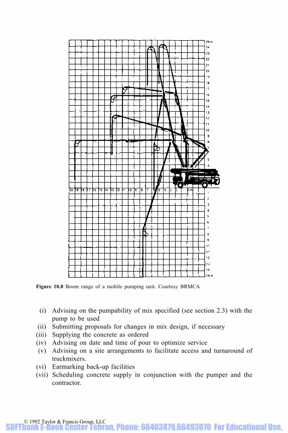
(i) Advising on the pumpability of mix specified (see section 2.3) with thepump to be used
(ii) Submitting proposals for changes in mix design, if necessary(iii) Supplying the concrete as ordered(iv) Advising on date and time of pour to optimize service(v) Advising on a site arrangements to facilitate access and turnaround of
truckmixers.(vi) Earmarking back-up facilities(vii) Scheduling concrete supply in conjunction with the pumper and the
contractor.
Figure 10.8 Boom range of a mobile pumping unit. Courtesy BRMCA
© 1992 Taylor & Francis Group, LLC SOFTbank E-Book Center Tehran, Phone: 66403879,66493070 For Educational Use.

11 Organizations
In the UK there are three organizations particularly concerned with ready-mixed concrete: the British Ready Mixed Concrete Association (BRMCA),British Aggregate Construction Materials Industries (BACMI) and theindependent Quality Scheme for Ready Mixed Concrete (QSRMC).
11.1 BRMCA
The British Ready Mixed Concrete Association was formed in 1950 by fivecompanies each operating one plant. As a trade association its role was torepresent its members’ interests in legal, commercial and technical matters.The need for recognition of the product by the construction industry as aviable alternative to site mixing dominated the work of the association in itsearly years, and the publication of BS 1926, ‘Methods for specifying ready-mixed concrete’, in 1962, was a significant milestone in the growth of theindustry leading up to 1968 when BRMCA members had over 800 plants inoperation. At this stage, the need to ensure that good trade practice was bothconfirmed and maintained, led to the introduction of the BRMCA’sAuthorization Scheme. This scheme laid down standards which ensured thatplants certified under its rules had the capability to produce quality concreteby employing suitably trained personnel, using materials of proven quality,operating modern plant and equipment and applying established methods ofconcrete mix design production control. The association employed charteredengineers to inspect the plants and enforce the agreed standards.
In 1972, an important option was added, covering quality controlprocedures for mixes designed for strength, and by 1981 the scheme covered1200 registered plants of which 300 were also registered for the designed mixoption.
At the end of 1981, with the formation of BACMI, the plants of the ready-mixed concrete industry were divided almost equally between the two tradeassociations, BRMCA and BACMI. BRMCA continued with its authorizationscheme until, in 1984, the independent Quality Assurance Scheme for ReadyMixed Concrete (QSRMC) was formed, when the plants of BRMCA andBACMI came again under a single scheme. Indeed, it became obligatory formembers of BRMCA and BACMI for their plants, including those erected onconstruction sites, to be registered under QSRMC.
At that time BRMCA resumed its original role as a trade associationrepresenting its members, particularly in the technical field, but without thedirect responsibility for the operation of a quality assurance scheme.
© 1992 Taylor & Francis Group, LLC SOFTbank E-Book Center Tehran, Phone: 66403879,66493070 For Educational Use.

11.2 BACMI
Formed in 1982, British Aggregate Construction Materials Industries(BACMI) is a federation representing the interests in the UK of the producersof construction aggregates (quarried stone, sand, gravel and slag), of lime forindustrial and agricultural uses, and of processed materials such as ready-mixed concrete and coated bituminous materials; asphalt and coated-macadamsurfacing contractors also form part of the federation.
On the formation of BACMI, the members who had ready-mixed concreteoperations formed a group which published a code of practice for theproduction and delivery of ready-mixed concrete based on BS 5750, Qualitysystems. It was a self-regulating scheme which was monitored by the federation,but although it fully met the standards of BS 5750 and was technically adequateand very economic to operate, it was not acceptable to many in the constructionindustry who had come to rely on an inspectorate. In 1984 BACMI supportedthe establishment of QSRMC, and it is currently mandatory on all members withready-mixed concrete operations in the UK to register with QSRMC.
BACMI continues to represent all its members’ interests, actively lobbyingon their behalf and promoting the wide range of products and services whichthey offer.
11.3 QSRMC
The Quality Scheme for Ready Mixed Concrete is an independent organizationsolely concerned with quality assessment and certification. The schemeoperated by QSRMC provides assurance that concrete is supplied inaccordance with quality and quantity requirements of the purchaser. TheScheme employs experienced, professional staff full-time for the assessmentof concrete production standards. The Scheme has an independent GoverningBoard.
11.3.1 Technical standards [128]
The technical regulations against which the assessments are made are given inAppendix 1. To be able to give the assurance offered by the Scheme, theproducers’ operating procedures are assessed against over 400 items in thethree categories of order processing, technical records and plant andproduction.
11.3.2 Order processing
To meet the criteria for certification, the producer must demonstrate that hisquality system and staff are:
(i) Interpreting specification requirements correctly(ii) Using valid technical data on mixes and materials(iii) Providing comprehensive quotations
© 1992 Taylor & Francis Group, LLC SOFTbank E-Book Center Tehran, Phone: 66403879,66493070 For Educational Use.

(iv) Receiving orders and issuing correct concrete mix productioninstructions
(v) Confirming the quality and quantity of materials used against thepurchaser’s orders.
11.3.3 Technical records
To demonstrate that he is capable of achieving the required standards, theproducer must show that he has the technical systems and competent personnelable to:
(i) Test materials to British Standards and the purchaser’s specification(ii) Design mixes for performance, prescription, water/cement ratio and yield
(iii) Perform tests in approved laboratories to British Standards(iv) Use a control system to maintain concrete quality to the required
standards.
Figure 11.1 Plant inspection by a QSRMC assessor. Courtesy C & G Concrete Ltd andQSRMC
© 1992 Taylor & Francis Group, LLC SOFTbank E-Book Center Tehran, Phone: 66403879,66493070 For Educational Use.

11.3.4 Plant and productionTo gain-and maintain-certification, the producer must demonstrate during theassessments and audits that his quality systems and personnel are able to:
(i) Control the delivery, handling, storage and mixing of materials(ii) Operate batching and mixing equipment(iii) Comply with batching procedures, instructions and batch recording(iv) Issue delivery tickets with full mix descriptions.
11.3.5 Continuing surveillance and enforcementAfter a Certificate of Accreditation has been issued, the producer is subject to:
(i) Regular surveillance visits to confirm the satisfactory operation of theapproved quality systems
(ii) Auditing of the quality system data to check compliance with both theQSRMC Regulations and purchasers’ requirements.
All certified producers are under a written binding obligation to maintain theirstandards and to correct any discrepancies promptly. Failure to do so canresult in a review, suspension or withdrawal of the Certificate of Accreditation.Continuing compliance with QSRMC Regulations is strictly enforced.
11.3.6 NACCB accreditationIn common with other certification bodies, QSRMC is accredited by theNational Accreditation Council for Certification Bodies (NACCB). In the caseof QSRMC the accreditation is not only for BS 5750: Part 1, Systems approval,but also for product conformity to the new EN 45001 and EN 45012.
11.4 NACCBThe National Accreditation Council for Certification Bodies (NACCB) isresponsible for approving Quality Assurance schemes such as CARES (UKCertification Authority for Reinforcing Steels) and QSRMC.
11.5 NAMASThe National Measurement Accreditation Service (NAMAS), a service of theNational Physical Laboratory, is responsible for approval of calibration andtesting laboratories. All laboratories are assessed to ensure compliance withthe requirements of ISO Guide 25 and EN 45001—the European Standard forthe competence of calibration and testing laboratories.
All members of QSRMC have to ensure that their strength testing meets notonly the QSRMC regulations, but also NAMAS regulations. Each controllaboratory is assessed and accredited, for the appropriate tests, by NAMAS.
Some QSRMC members operate laboratories that are fully accredited byNAMAS for a wider range of tests, and which function as commerciallaboratories.
© 1992 Taylor & Francis Group, LLC SOFTbank E-Book Center Tehran, Phone: 66403879,66493070 For Educational Use.

Appendix 1: QSRMC technicalregulations
The following schedule forms the basis of the QSRMC TechnicalRegulations.
1 Introduction
Members shall comply with these technical requirements for the Production,Control and Supply of Ready Mixed Concrete.
2 Quality System
2.1 An effective and economical quality system shall be established and maintainedin accordance with BS 5750 Part 1 to ensure and demonstrate that the concreteconforms to the specification agreed with the purchaser and with theserequirements.
2.2 The system shall cover:
* Members’ Quality Responsibilities* Planning to Meet Quality Requirements (Concrete Mixes—Basis of Supply,
Description, Materials and Mix Design)* Production and Delivery* Materials and Production Control* Product Quality Control* Training* Review of the Quality System* Records.
2.3 The adoption of the detailed procedures contained in the QSRMC TechnicalRegulations’ shall be deemed to satisfy the technical requirements.
2.4 Alternative procedures may be approved if the same degree of assurance isprovided, and the procedures are fully documented and available to QSRMC forassessment.
3 Members’ Quality Responsibilities 3.1 The Member shall nominate one or more representatives to be responsible for
© 1992 Taylor & Francis Group, LLC SOFTbank E-Book Center Tehran, Phone: 66403879,66493070 For Educational Use.

implementing and maintaining the standards of the Scheme and shall define theresponsibilities and authorities delegated to other staff.
3.2 All staff shall be technically competent for the functions they perform and awareof the effects of these functions on quality.
4 Technical Definitions 4.1 Concrete:
Concrete is defined as a mixture of aggregate, cementitious material and water,with or without admixtures and/or additions, and including entrapped or entrainedair, for all uses, but excluding all mortars as defined in BS 2787 other than foruse as floor and roof screeds.
4.2 Quantity:The basis of supply shall be the cubic metre of fully compacted, fresh concretedetermined in accordance with BS 1881 Part 107. For lean concrete, fullcompaction is considered to be compaction to refusal in accordance with Clause1040(3) of the Department of Transport “Specification for Highway Work(1986)”. (There is a separate requirement for semi-dry concrete.)
4.3 Designed Mix:A mix described in performance terms and for which strength testing will form anessential part of judgement of compliance.
4.4 Prescribed Mix:A mix described in terms of proportions, whether by weight, volume or cementcontent per cubic metre. A prescribed mix is a mix complying with BS 5328 Part2 Section 3. Prescribed mixes are mixes selected for particular properties.Strength testing does not form part of the rules for judging compliance ofprescribed mixes.
4.5 Cementitious Material:A cement, or a combination of a cement and pulverised fuel ash complying withBS 3982 Part I, or a combination of a cement and ground granulated blastfurnaceslag complying with BS 6699.
4.6 Cement:Cement is a material defined as such in a British Standard.
4.7 Admixtures:Admixtures are substances added to mixes in very small quantities (with theexception of pigments typically less than 1% by volume) to modify definedproperties of concrete by their chemical and/or physical effect.
© 1992 Taylor & Francis Group, LLC SOFTbank E-Book Center Tehran, Phone: 66403879,66493070 For Educational Use.
4.8 Additions:Additions are substances, including pulverised fuel ash and ground granulatedblastfurnace slag, added to concrete mixes to improve certain properties by theirchemical and physical effects and form a significant fraction of the total volumeof the concrete.
5 Planning to Meet Quality Requirements: (Concrete Mixes—Basis of Supply,
Description, Materials and Mix Design) 5.1 Basis of Supply:
(i) Ready mixed concrete shall be supplied having the quality and in thequantity necessary to satisfy the requirements agreed with the purchaser orhis agent,
(ii) Concrete mixes and materials shall be supplied either:a. in accordance with BS 5328 unless agreed otherwise with the purchaser, orb. in accordance with the purchaser’s specification, orc. as agreed alternatives to the purchaser’s specification.
5.2 Establishing Quality Requirements:Specifications and orders shall be systematically reviewed by a competent personto interpret the specified requirements and relate these to mix design criteria.These shall be formally recorded together with any modification to thespecification resulting from subsequent documentation to ensure that the plantoperator is given the correct instructions for batching and mixing.
5.3 Description of Concrete Mixes:(i) Mixes supplied in accordance with Clause 5.1(ii)b shall be agreed in the
order and quotation and shall be described as specified,(ii) Mixes supplied in accordance with Clause 5.1(ii)a or c shall be described as
one or other of the following:a. Designed mixesb. Designed mixes with additional requirementsc. Prescribed mixes, either in terms of:
* special prescribed mixes to BS 5328 using the letters SP and the contentof the cementitious material in kilograms per cubic metre (e.g. SP 300).
* standard mixes* proportions by weight or volume
d. Other descriptions as defined in national specifications.e. Mixes supplied as proprietary mixes or marketed under a registered trade
name shall be fully described in accordance with Clause 5.3 (ii)a–d anddescribed on the delivery ticket in accordance with Clause 6.5 (i)b.
(iii) For mixes or materials offered as alternatives to specified mixes or wherethere is no specification, orders, whether received verbally or in writing,shall be agreed with the purchaser and the fact recorded.
5.4 Constituent MaterialsAll materials shall be supplied in accordance with the agreement with thepurchaser and in accordance with the Regulations.
© 1992 Taylor & Francis Group, LLC SOFTbank E-Book Center Tehran, Phone: 66403879,66493070 For Educational Use.

(i) Cementitious materialsa. Cementitious materials shall be as specified or any alternative agreed with
the purchaser and the fact recorded. The cement type shall be one of thefollowing:BS 12, BS 146, BS 4027, BS 6588
b. Combinations equivalent to BS 146, BS 6588 and BS 4246 may beproduced by blending of the constituents in the concrete mixer subject tothe provisions of Clause 7.1(ii) and (iii). These combinations shall bedescribed as P/BF, P/PFA and LHP/BF respectively under the heading ofCementitious materials.
d. Combinations equivalent to BS 6588, or BS 6588 Cements shall not beused in Nominal Mixes,
(ii) Aggregatesa. Aggregates shall be as specified or any alternative agreed with the
purchaser and the fact recorded. Where no specification exists, aggregatesshall comply with one of the following British Standards:
BS 882, BS 877, BS 1047, BS 1165, BS 3797
b. Other aggregates, including types of gradings not covered by one of theabove British Standards, may be used by other than ordinary prescribedmixes, provided there are satisfactory data on the properties of concretemade with them.
c. Separate fine and coarse aggregates shall be used except for BS 5328grade C15 and below, or whenever concrete is specified by nominal all-in proportions, where all-in reconstituted aggregate may be used,
(iii) WaterWhere mains water is not available, water shall comply with Appendix Aof BS 3148.
(iv) Admixtures and Additionsa. For all concrete mixes, admixtures and additions shall only be used where
specified or agreed with the purchaser.b. Where additions are used, the percentage of addition expressed as a
proportion of the cement plus addition content shall be declared to thepurchaser.
c. Pulverized-fuel ash or ground granulated blastfurnace slag may be used asa replacement for any specified minimum cement content, where specifiedor agreed with the purchaser, the fact recorded and declared in accordancewith Clause 6.5(iv).
d. Any quotation or offer by a Member to include admixtures and additionsin a mix shall be made in such a way that the purchaser’s agreement isobtained by a definite response to the quotation/offer.
e. Pulverized-fuel ash shall comply with BS 3892 Part 1 unless otherwiseagreed with the purchaser in writing.
f. Ground granulated blastfurnace slag shall comply with BS 6699.h. Pulverised fuel ash or cements to BS 6588 shall not be used as a
replacement for any specified cement content in Nominal Mixes.
© 1992 Taylor & Francis Group, LLC SOFTbank E-Book Center Tehran, Phone: 66403879,66493070 For Educational Use.

5.5 Concrete Mix Design(i) Concrete mix proportions shall be established for every plant to cover quality
and quantity requirements. This programme shall be established prior toproduction and subsequent to significant changes in materials or concreteproperties,
(ii) All mixes shall be designed to yield the declared volume. 5.6 Designed Mixes:
(i) Designed mixes shall be designed to achieve a target of not more than 2.5%of test results below the specified strength in order to adequately meet thecompliance requirements of BS 5328, unless the purchaser’s specification orits compliance rules require a lower value to be adopted,
(ii) All concrete mix designs shall take full account of the relevance andaccuracy of available data relating strength to cement content, the number oftest results available from the control system for assessing standard deviationand the achieved rate of testing.
(iii) The basis of assessment of all concrete mix designs shall be that describedin the QSRMC ‘Technical Regulations’.
5.7 Prescribed Mixes:
Mix proportions, dependent upon the method of description (see Clause 5.3(ii) cand d), shall be established for each plant supplying prescribed mixes.
6 Production and Delivery 6.1 Plant and Equipment:
(i) At each plant, efficient equipment shall be provided and maintained toensure the capability to produce and deliver a range of concrete mixes to thestandards specified in BS 5328 in respect of quality and quantity
(ii) Methods of materials storage and handling, and concrete production anddelivery, shall ensure that risks are minimised of non-compliance,intermingling, contamination, segregation, errors, loss of materials orconcrete, and the influences of weather.
6.2 Maintenance:
All plant and equipment shall be maintained in a clean and efficient workingcondition and regular, routine maintenance checks shall be carried out.
6.3 Measurement of Materials:(i) The batching equipment shall be regularly calibrated and maintained to the
accuracy of the requirements of BS 5328 and shall permit the plant operativeto comply with Clause 6.3(iii).
(ii) The plant operative shall be provided with a clear display of the quantitiesof materials to be batched for each mix and batch size and with information
© 1992 Taylor & Francis Group, LLC SOFTbank E-Book Center Tehran, Phone: 66403879,66493070 For Educational Use.

identifying the display to be selected for each designed and prescribed mixto be produced.
(iii) The plant operative shall batch the correct amounts of each material for therequired mix design and size of batch within the tolerance of BS 5328.
6.4 Mixing and Transporting:
The methods of mixing and transporting shall comply with BS 5328.
6.5 Delivery Ticket Information:(i) Immediately before discharging the concrete at the point of delivery, the
supplier shall provide the purchaser with a preprinted delivery ticket inaccordance with BS 5328.
(ii) The mix shall be described on the delivery ticket in terms of the appropriatecategory in Clauses 5.3(i) or (ii).
(iii) Combinations of cementitious materials shall be declared in accordance withClause 5.4(i)b.
(iv) Admixtures and additions shall be declared by word or code which clearlyidentifies the type or name of the admixture or addition.
7 Materials and Production Control 7.1 Control and Purchased Materials Quality:
(i) A control system shall be operated to provide assurance that all materialspurchased for, and used in, the production of concrete conform to thestandards agreed with the supplier.
(ii) Where combinations of ordinary Portland cement and ground granulatedblastfurnace slag are blended in the mixer and declared as P/BF or LHP/BF,tests shall be carried out monthly to confirm equivalence with BS 146 or BS4246 respectively.
(iii) Where combinations of ordinary Portland cement and pulverised-fuel ashcomplying with BS 3892 Part 1 are blended in the mixer and declared as P/PFA, tests shall be carried out monthly to confirm equivalence with BS 6588“Portland pulverised-fuel ash cement”.
7.2 Production Control:
The production of concrete at each plant shall be systematically controlled so asto provide assurance that all concrete supplied shall be in accordance with theserequirements and with the purchaser’s specification, BS 5238 or the agreeddescription in respect of quality and quantity of concrete.
7.3 Inspection of Concrete:Each load of mixed concrete shall be inspected following mixing, before despatchand prior to discharge.
7.4 Workability Control:The workability of concrete shall be controlled on a continuous basis duringproduction and any corrective action necessary taken.
© 1992 Taylor & Francis Group, LLC SOFTbank E-Book Center Tehran, Phone: 66403879,66493070 For Educational Use.

7.5 Additional Water:No additional water, other than the amount required to produce the specifiedworkability, shall be added to the truckmixer drum before discharge unlessspecifically requested and signed for by the purchaser.
7.6 Instructions:Instructions emanating from the operation of the quality system which affect theproduction control shall be supplied to the production staff.
7.7 Plant Inspections:Regular routine inspections shall be carried out on the condition of plant andequipment, including delivery vehicles.
8 Product Quality Control 8.1 Workability, Plastic Density, Temperature and Air Content
Concrete mixes shall be randomly sampled and tested for workability, plasticdensity and, where appropriate, temperature and air content. When significantvariations from target values are detected, corrective action shall be taken.
8.2 Designed Mixes(i) A quality control system shall be operated to control the strength of designed
mixes to the levels required by Clause 5.6(i) and shall be based on randomtests of mixes which form the major proportion of production. The systemshall include continuous analysis of results from cube tests to compare actualwith target values together with procedures for modifying mix proportions tocorrect for observed differences.
(ii) The control system, when assessed in its entirety, shall ensure that thequality of concrete produced, is at least as high as that required to satisfyClause 5.6.
(iii) All upward changes in cement content shall be mandatory unless the causeof the change has been identified and satisfactory corrective action taken.Upward changes shall be made immediately they are indicated as beingnecessary.
(iv) Downward changes in cement content indicated by the control system shallbe discretionary.
8.3 Prescribed Mixes
Periodic and systematic checks shall be made to ensure that the cement contentsof prescribed mixes comply with their mix descriptions.
8.4 Testing Standards and Laboratories:All testing in the field and laboratory to mix design and quality control purposesshall comply with the appropriate British Standards and, for strength testing,NAMAS regulations.
© 1992 Taylor & Francis Group, LLC SOFTbank E-Book Center Tehran, Phone: 66403879,66493070 For Educational Use.

9 Training 9.1 All personnel concerned with production, delivery and the quality system shall
have received training appropriate to the duties they perform.
9.2 The testing of materials, proportioning of mixes and the production of concretetogether with all its control testing shall be under the overall supervision of anexperienced concrete technologist who shall be trained to a standard at leastequivalent to the CGLI Concrete Technology and Construction Certificate.
9.3 Concrete shall be batched by operatives who have received proper instructions onthe equipment in use and who are able to comply with the required accuracy ofbatching.
10 Review of the Quality System
The quality system established in accordance with these requirements shall beperiodically and systematically reviewed at least once each year to ensurecontinued effectiveness of the system.
11 RecordsRecords shall be maintained to provide continuous assurance of effectiveoperation of the Quality System so as to confirm the quality and quantity ofconcrete produced. The records shall be retained for the purposes of theserequirements for a period of at least one year. The records shall permit traceabilityand shall include changes occurring, and corrective action taken. They shall coverthe following aspects:
* Planning to Meet Quality Requirements
— order processing— data to substantiate concrete mix designs for quality and quantity
* Production and Delivery— batching instructions— batching records— delivery tickets— equipment calibration and plant maintenance
* Materials and Production Control— concrete production and materials purchase, usage and stocks— certificates or test results for materials
* Product Quality Control— control test results— quality control system analyses— test equipment calibrations— laboratory accreditation (where applicable)
© 1992 Taylor & Francis Group, LLC SOFTbank E-Book Center Tehran, Phone: 66403879,66493070 For Educational Use.

Appendix 2: Conversion factors
As calculators are usually available, conversion factors are given rather than tables.
© 1992 Taylor & Francis Group, LLC SOFTbank E-Book Center Tehran, Phone: 66403879,66493070 For Educational Use.

Vehicle conversion factors
© 1992 Taylor & Francis Group, LLC SOFTbank E-Book Center Tehran, Phone: 66403879,66493070 For Educational Use.

Appendix 3: Designated mixes inaccordance with BS 5328: Part 2Section 5
Table A.1 Characteristics of designated mixes with aggregate of 20 mm nominal maximum size
Notes:(1) This table is based on Table 6 of BS 5328: Part 2:1991(2) See Table A.2 for cement groups(3) Depending on the proportion of pfa, a cement complying with BS 6588 may be classified
as a Group 2 cement(4) The PAV mixes contain an air-entraining admixture to give the appropriate air content by
volume (see Table 9.3)(5) See note 2 to Table A.2
© 1992 Taylor & Francis Group, LLC SOFTbank E-Book Center Tehran, Phone: 66403879,66493070 For Educational Use.

Table A.2 Cement groups
Table A.3 Equivalent grades for cement content and free W/C ratiofor different standard strength classes of cements
Notes:(1) This table is based on BS 5328: Part 2:1991, Clause 16.1(2) BRE Digest 363, July 1991 permits ggbs and pfa cements and combinations with pc to be
used in Class 4 sulphate conditions
Notes:(1) This table is based on Table 14 of BS 5328: Part 1:1991 as
amended in 1992(2) The equivalent grade may be selected from the table provided:
(a) the nominal max aggregate size is between 10 and 40 mm(b) the specified slump is in the range 50 mm to 150 mm(c) admixtures providing water reduction are not included
© 1992 Taylor & Francis Group, LLC SOFTbank E-Book Center Tehran, Phone: 66403879,66493070 For Educational Use.

Table A.4 Mixes for typical jobs
© 1992 Taylor & Francis Group, LLC SOFTbank E-Book Center Tehran, Phone: 66403879,66493070 For Educational Use.

Table A.4 (Contd.)
Note: This table is based on Table 13 of BS 5328: Part 1:1991
© 1992 Taylor & Francis Group, LLC SOFTbank E-Book Center Tehran, Phone: 66403879,66493070 For Educational Use.

References
1. Cassel, M. The Readymixers. Pencorp, 1986.2. Wigmore, V.S. Ready-mixed concrete. Reinforced Concrete Review, December 1961.3. Staples, P.N. Trends in ready-mixed concrete. Concrete, November 1984.4. Teychenne, D.C. The use of crushed rock aggregates in concrete. HMSO, Garston 1978,
74pp.5. Collis, L. and Fox, R.A. Aggregates: sand, gravel and crushed rock aggregates for
construction purposes. The Geological Society, London, 1985, 220pp.6. Collins, R.J. Concrete from crushed Jurassic limestone. Quarry Management and Products,
March 1983, 127–138.7. Spreull, W.J. and Uren, J.M.L. Marine aggregates and aspects of their use especially in the
South East of England. St. Albans Sand and Gravel Co. Ltd., and Civil and Marine Ltd.,March 1986, 62pp.
8. Marine dredged aggregates—a technical appraisal. British Aggregate ConstructionMaterials Industry, London, 1987, 1–15.
9. BACMI Statistical Yearbook, British Aggregate Construction Materials Industry, London,1990.
10. Carr, M.P. and Banfill, P.F.G. The use of fine marine-dredged sand in concrete. Universityof Liverpool, September 1984, 70 pp.
11. Banfill, P.F.G. and Carr, M.P. The properties of concrete made with very fine sand.Concrete, (London) March 1987, 11–16.
12. Dewar, J.D. The Structure of Fresh Concrete. First Sir Frederick Lea Memorial Lecture,Southampton. Institute of Concrete Technology, 1986, BRMCA reprint, 1–23.
13. Dewar, J.D. Quality requirements of aggregates for ready-mixed concrete. QuarryManagers’ Journal, London, Vol. 51, No. 9, September 1967, 348–352.
14. Banfill, P.F.G. Alternative materials for concrete—Mersey silt as fine aggregate. Buildingand Environment, 1980, Vol. 15, 181–190.
15. Significance of tests and properties of concrete and concrete making materials. ASTMSpecial Publication 169B, American Society for Testing and Materials, Philadelphia, 1978,754.
16. Dewar, J.D. Computerised simulation of aggregate, mortar and concrete mixes. ERMCOCongress, London, 1983, Paper W8B(2).
17. Dewar, J.D. The workability and compressive strength of concrete made with sea water.Cement and Concrete Association TRA/374, December 1963.
18. Russell, P. Effect of aggregates on durability. Supplement to The Consulting Engineer,London, April/May 1971.
19. Lees, T.P. Impurities in concreting aggregates. C & CA Guide, Cement and ConcreteAssociation, London, 1987, 7 pp.
20. Dewar, J.D. Effect of mica in the fine aggregate on the water requirement and strength ofconcrete. Cement and Concrete Association, TRA/370, Slough 1963.
21. Forder, I.E. Some effects of mica in concrete. Ready Mixed Concrete (South West) Ltd.,1971, 34.
22. Concrete Society. Alkali-silica reaction—minimising the risk of damage. 1987. TechnicalReport No. 30.
23. Shacklock, B.W. Durability of concrete made with sea dredged aggregates. Proc. Symp. SeaDredged Aggregates for Concrete, SAGA, Slough 1968, 31–33.
24. Chapman, G.P. and Roeder, A.R. Properties of concrete made with aggregates containingsea-shells. SAGA, London, May 1969, SR 6901 34.
25. Grant, N.T. Sands in ready mixed concrete Proc. Symp. Sands for Concrete, SAGA, London1964, 40–47.
© 1992 Taylor & Francis Group, LLC SOFTbank E-Book Center Tehran, Phone: 66403879,66493070 For Educational Use.

26. Building Research Establishment, BRE Digest 357, Shrinkage of natural aggregates inconcrete, HMSO, London, January 1991.
27. Dewar, J.D. Some properties of a lightweight concrete made with expanded perliteaggregate. Cement and Concrete Association, London, TRA/388, May 1965.
28. Concrete Society, Lightweight aggregate for structural concrete. Concrete Society DataSheet. Concrete, London, August 1980.
29. Spratt, B.H. An Introduction to Lightweight Concrete. Sixth edn. Cement and ConcreteAssociation, Slough, 1980, 15.
30. Miller, E.W. High density concrete, Parts 1 & 2. Current practice sheet No 90. Concrete,London, December 1983, January 1984.
31. Corish, A.T. Personal communication.32. Corish, A.T. and Jackson, P.J. Portland cement properties—past and present. Concrete,
London, Vol. 16, No. 7, July 1982, 16–18.33. ASTM C451–89 Test method for early stiffening of cement paste. American Society for
Testing and Materials, Philadelphia.34. Jackson, P.J. Modern British Portland cements. Conference on Concrete in Construction,
Stoneleigh, October 1985, 14.35. Jones, P.R., Reeves, C.M. and Dewar, J.D. Progress in the use of ground granulated blast
furnace slag by the UK ready mixed concrete industry. Int. Conf. on Slags and BlendedCements, Mons, Belgium, September 1981, 10.
36. Dewar, J.D. Quality Assurance of ready mixed concrete incorporating ground granulatedblast furnace slag in the United Kingdom. Slag Workshop, Pennsylvania State University,March 1984, 1–13.
37. Dewar, J.D. Standards, codes and quality assurance for the use of ggbfs in ready mixedconcrete. Conf. on the Use of ggbfs in Concrete, London, 1986.
38. Dewar, J.D. (1) Introduction to BS 3892: Pulverised fuel ash for use in concrete, (2)Pulverised fuel ash concrete and the UK ready mixed concrete industry and supplement.Joint Seminar: the use of pulverised fuel ash in concrete and in the manufacture of ordinaryPortland cement, The Hong Kong Institution of Engineers and The Concrete Society ofHong Kong, September 1982.
39. Dewar, J.D. Specifying composite cements, pulverised-fuel ash and ground granulatedblastfurnace slag in concrete Concrete, London, August 1985, 30.
40. Bamforth, P.B. Mass concrete. Concrete Society Digest No. 2, Concrete Society, London,1984, 8.
41. Quality Scheme for Ready Mixed Concrete Manual of Quality Systems for Concrete,QSRMC, Walton-on-Thames, May 1984, 31.
42. Basis for certification procedures for testing blends of BS 12 Portland cement and ggbfsor pfa. BRMCA, TB/19/1986, British Ready Mixed Concrete Association, London, 1986.
43. Basis for certification procedures for testing blends of BS 12 Portland cement and ggbfsor pfa. BACMI, Technical Note No. 4, British Aggregate Construction Materials Industry,London, 1987.
44. Building Research Establishment, BRE Digest 363, Sulphate and acid resistance ofconcrete in the ground, HMSO London, July 1991.
45. Brown, B.V. Air-entrainment-Part 1 and Part 2. Current Practice sheets 80 and 81.Concrete, London, December 1982 and January 1983, pp. 59, 60, 45, 46.
46. Waddicor, M.J. A study of some variables within pulverized-fuel ashes which affect the air-entraining ability of admixtures in concrete. ERMCO, London, 1983, Congress paperW12A(3), 7.
47. Dunstan, M.H. High fly ash content concrete. ERMCO, London, 1983, Congress paperW9A(4), 8.
48. Dhir, R.K., Munday, J.G.L. and Ong, L.T. Strength variability of opc/pfa concrete.Concrete, June 1981, London, 33–36.
49. Guide to Chemical Admixtures for Concrete. Concrete Society Technical Report No. 18,August 1980, 16.
50. Dewar, J.D. Concrete reasons for admixtures and additions. Contract Journal, London, 17February 1983, 14–15.
51. Sandberg, A. and Collis, L. Toil and troubles on concrete bubbles. Consulting Engineer,London, November 1982, 32, 35.
52. Hewlett, P.C. and Edmeades, R.M. Superplasticised concrete, Parts 1 and 2. CurrentPractice Sheets 94 & 95, Concrete, London, April and May 1984, 31, 32.
© 1992 Taylor & Francis Group, LLC SOFTbank E-Book Center Tehran, Phone: 66403879,66493070 For Educational Use.

53. Levitt, M. Pigments for concrete and mortar. Concrete, London, March 1985, 21–22.54. Aitcin, P.C., Pinsonneault, P. and Roy, D.M. Physical and chemical characterization of
condensed silica fumes. Ceramic Bulletin 63(12), 1984, 1487–1491.55. Parker, D.G. Microsilica concrete. Part 1: The Material. Part 2: In use. Concrete, London,
October 1985, 21, 22, March 1986, 19–21.56. Malhotra, V.M. and Carette, G.G. Silica fume concrete—Properties, applications and
limitations. Concrete International, May 1983, 40–46.57. Markestad, S.A. A study of the combined influence of condensed silica fume and a water-
reducing admixture on water demand and strength of concrete. Bordas-Gauthier-Villars,Paris, 1986, Matériaux et Constructions, Vol. 19, No. 109, 39–47.
58. Page, C.L. Influence of microsilica on compressive strength of concrete made from Britishcement and aggregates. University of Aston, Birmingham,February 1983, 9.
59. American Concrete Institute, State of the Art Report on fibre re-inforced concrete. Reportof ACI Committee 544. Concrete International, May 1982, 9–30.
60. Hannant, D.J. Fibre reinforced cement and concrete. Concrete Society, London,February and March 1984. Concrete Current Practice Sheets 92 and 94, pp.25, 26 and21, 22.
61. Dewar, J.D. The workability of ready-mixed concrete. RILEM, Leeds 1973.62. Newman, K. Properties of concrete. Structural Concrete, London, Vol. 2, No. 11,
September/October 1965, 451–482.63. Tattersall, G.H. Practical user experience with the two-point workability test. University of
Sheffield, May 1983, BS74, 9.64. Dewar, J.D. Relations between various workability control tests for ready-mixed concrete.
Cement and Concrete Association, TRA/375, February 1964.65. BACMI/BRMCA/CMF/C & CA Joint Working Party 1986: proposal for inclusion in BS
5328.67. Wiltshire, D.E. Concrete pumping. Concrete Society, Current Practice Sheet No. 79,
Concrete, London, November 1982.68. The Manual of Pumped Concrete Practice, British Concrete Pumping Association,
Harrogate, undated, 1977 or later, 93.69. Laing Design and Development Centre, Pumping concrete. Digest No. 1. Concrete Society,
London, 1984, 7.70. Gaynor, R.D. Meininger, R.C. and Khan, T.S. Effect of temperature and delivery time on
concrete properties. Temperature effects on concrete. ASTM STP 858, American Society forTesting and Materials, Philadelphia, 1985, 68–87.
71. Dewar, J.D. Some effects of prolonged agitation of concrete. Cement and ConcreteAssociation, TRA/367, December 1962.
72. Dewar, J.D. Some effects of prolonged agitation of concrete. London Cement, Lime andGravel, April 1963, 121–128.
73. Gaynor, R.D. Ready mixed concrete. Significance of tests and properties of concrete andconcrete making materials. ASTM Special Publication 169B, American Society for Testingand Materials, Philadelphia, 1978, 471–502.
74. Monks, W. Visual concrete—design and production. Appearance Matters, No. 1. Cementand Concrete Association, Slough, 1980, 28.
75. Blake, L.S. Recommendations for the production of high quality concrete surfaces. Cementand Concrete Association, Slough, 1967, 38.
76. Monks, W. Visual concrete—the control of blemishes in concrete. Appearance Matters, No.3, Cement and Concrete Association, Slough, 1981, 20.
77. Non-structural cracks in concrete. Report of a working party. Technical Report No. 22,Concrete Society, London, December 1982, 38.
78. Dewar, J.D. The indirect tensile strength of concrete of high compressive strength. Cementand Concrete Association, TRA/377, March 1964.
79. Dewar, J.D. High strength concrete. Cement and Concrete Association, Slough, 1964, DN/81.
80. Dewar, J.D. Mix design for ready-mixed concrete. The Municipal Engineer, London,February 1986, 35–43.
81. Deacon, C. and Dewar, J.D. Concrete durability—specifying more simply and surely bystrength. Concrete, London, February 1982.
82. Grant, N.T. and Warren, P.A. A CUSUM controlled accelerated curing system for concretestrength forecasting. ERMCO Congress 1977, Stockholm, 314–343.
© 1992 Taylor & Francis Group, LLC SOFTbank E-Book Center Tehran, Phone: 66403879,66493070 For Educational Use.

83. Dhir, R.K. Accelerated strength testing. Concrete Society, London. Concrete, October 1976,Current Practice Sheet No. 34.
84. Dhir, R.K. and Gilhespie, R.Y. Concrete quality assessment rapidly and confidently byaccelerated strength testing. Congress paper W14A(1), ERMCO, London 1983, 8.
85. Dewar, J.D. Testing concrete for durability. Concrete, London, Part 1, Vol. 19, No. 6, June1985, 40–41; Part 2, Vol. 19, No. 7, July 1985, 40–41.
86. Spears, R.E. The 80 per cent solution to inadequate curing problems. Concrete International,April 1983 (quoting research of T.C. Powers and of R.E. Carrier and P.D. Cady).
87. Concrete Mixes—an introduction to the BRMCA Method of Mix Design. British ReadyMixed Concrete Association, Shepperton, May 1984, 21.
88. Teychenne, D.C., Franklin, R.E. and Erntroy, H.C. Design of Normal Concrete Mixes.Department of Environment. HMSO, London, 1975, 31.
89. Deacon, C. and Hopwood, R. National Grades for concrete-progress towards a system ofspecifying concrete by strength grade in the United Kingdom. Congress paper G8(3),ERMCO, London 1983, 9.
90. Harris, C.A.R. Statistics for concrete—Part 1. Concrete Society Digest No. 5, ConcreteSociety, London 1984, 7.
91. Barber, P. and Sym, R. An assessment of the variability in ready mixed concrete in theUnited Kingdom. Congress Paper. W8B(4), ERMCO, London 1983, 1–6.
92. Metcalf, J.B. The specification of concrete strength. Part II: The distribution of strength ofconcrete for structures in concrete practice. TRRL Report LR 300, Transport and RoadResearch Laboratory, Crowthorne, 1970, 22.
93. Mathews, D.H. and Metcalf, J.B. The specification of concrete strength. Part III: The designof acceptance criteria for the strength of concrete. TRRL Report LR 301, Transport andRoad Research Laboratory, Crowthorne 1970, 18.
94. Metcalf, J.B. The specification of concrete strength. Part I: The statistical implications ofsome current specifications and codes of practice. TRRL Report LR 299, Transport andRoad Research Laboratory, Crowthorne, 1970, 41.
95. Brown, B.V. Statistical compliance with strength specifications. Congress paper W13A(3)ERMCO, London, 1983, 8.
96. Warren, P.A. The Quality Control of Ready Mixed Concrete. RMC Technical ServicesLimited.
97. Dewar, J.D. Quality control and strength tests—better benefits on way to user. ConstructionNews, Supplement, London, 11 May 1972.
98. Dewar, J.D. Specification, quality assurance and quality control of ready mixed concrete.Municipal Engineer, June 1987.
99. Day, K.W. Concrete control by cusum method. Congress paper W13A(2), ERMCO,London, 1983, 8.
100. Brown, B.V. Monitoring concrete by the CUSUM system. Concrete Society Digest No. 6,Concrete Society, London, 1984, 8.
101. Sheriff, T. Reference testing and the specification. ERMCO Congress 1977, Stockholm,269–312.
102. BRMCA Concrete Control System. BRMCA Guide. British Ready Mixed ConcreteAssociation, Shepperton, June 1984, 4.
103. Barber, P.M. and Sym, R. An assessment of a “Target Value” method of quality control.Paper W13A(1), 7th ERMCO Congress, London 22–26 May 1983, 1–7.
104. Pateman, J.D. Influence of site curing on the compressive strength of cubes. Concrete,London, February 1977, 30–31.
105. Foote, P. Comparative cube testing—a review. Concrete, London, December 1983, C&CAreprint 6/83, 2.
106. Kirkbride, T.W. Testing the testers. Reprint from Civil Engineering, December 1975, 3.107. The performance of existing testing machines. Concrete Society, PCS 62 London, July
1971.108. Rogers, J. and Hopwood, R. The development of Laboratory accreditation in the United
Kingdom. Congress paper W14A(4), ERMCO, London, 1983, 8.109. Concrete Laboratories: Register of Test Houses. British Ready Mixed Concrete Association,
London, published annually, 5.110. Osbaeck, B. Heat of hydration and strength of slag-Portland cement mixtures. Workshop on
blastfurnace slag cements and concretes, York, 1985, Vol. 4, 28.111. Concrete Core Testing for Strength. Second edition, including addendum, Technical Report
© 1992 Taylor & Francis Group, LLC SOFTbank E-Book Center Tehran, Phone: 66403879,66493070 For Educational Use.

No. 11, Concrete Society, London, 1987.112. Changes in the properties of ordinary Portland cement and their effects on concrete. A
working party report. Concrete Society, London, 1987 (to be published).113. Newman, K. The ready mixed concrete producers role in-situ/ndt testing. Conference on
Testing of Concrete, Ottawa, 1982.114. Dewar, J.D. Increasing the quality of concrete in an existing structure. RILEM Symp. on
Quality Control in Concrete Structures, Stockholm, June 1979, Vol. 2, 29–36.115. Samarin, A. Private communication.116. An assessment of the likely test variations in the analysis of fresh concrete. BRMCA TR10.
British Ready Mixed Concrete Association, Shepperton, June 1976, 5.117. The chemical analysis of hardened concrete. Concrete Society Technical Report No. 32,
1989.118. Ryle, R. Chemical analysis of hardened concrete. RMC Technical Services Ltd., Egham,
Surrey, Technical Report No. 64, January 1970, reprinted February 1973, 9.119. Bennett, P.E. The functional design of the ready-mixed concrete plant. Quarry
Management and Products, June 1976.120. Smit, J. Computerisation for quality concrete. Concrete, August 1984.121. Gilman, F.E. Improvement of management techniques for quality production and service in
small and medium companies. Concrete, May 1986.122. Truckmixers. BRMCA Fact Sheet 509. British Ready Mixed Concrete Association, June
1981.123. Aids to placing ready-mixed concrete. BRMCA Information Sheet 214 (Scotland) British
Ready Mixed Concrete Association, June 1980.124. Blackledge, G.F. Placing and compacting concrete. Concrete Society, Current Practice
Sheets No. 61 and 62, 1981.125. Birt, J.C. Curing concrete. Concrete Society Digest, No. 3, The Concrete Society, London,
1984.126. Specifying concrete—general aspects. BRMCA Advisory Sheet 501. British Ready Mixed
Concrete Association, London, July 1986.127. Costing concrete site-mixing. BRMCA Information Sheet 212. British Ready Mixed
Concrete Association, London, March 1979.128. Quality Scheme for Ready Mixed Concrete, Manual of Quality Systems for Concrete,
QSRMC, Walton-on-Thames, 1986.129. Anson, M. Aston D.E. and Cooke, T.H. The pumping of concrete: a comparison between
the UK and West Germany. University of Lancaster.130. Neville, A.M. Properties of Concrete. 3rd edition, Pitman Books, 1981, 150 (Fig. 3.8).131. Beaufait, F.W. Effects of improper handling of ready-mixed concrete. Proc. Int. Conf. on
Advances in Ready Mixed Concrete Technology, Dundee, Sept Oct 1975, ed. R.K.Dhir,Pergamon, Oxford, 359–366.
132. Ryle, R. The influence of test machines on cylinder splitting strength. Technical Report No.77, RMC Technical Services Ltd, Egham, 1973.
133. Warren, P.A. Assessing the validity of the cube test result. London Concrete SocietySymposium: Engineering judgement on the strength of concrete in structures, February1975, 20.
134. Popovics, S. New formulae for the prediction of the effect of porosity on concrete strength.ACI Journal, March-April 1985, 136–146.
135. Stilwell, J. BRMCA figures show up test house failings. New Civil Engineer, London, 31August 1972.
136. Anderson, R. Ready mixed concrete. Journal of the Institute of Clerks of Works, October,November, December 1979.
137. BRMCA Guide: British Ready Mixed Concrete Association, 1971.138. Gage, M. and Newman, K. Specification and Use of Ready Mixed Concrete. The
Architectural Press, 1972.139. Anderson, R. Developments in Works Practice—Concrete Specification. Institute of Works
and Highways Technician Engineers.140. Gaynor, R.D. and Mullarky, J.I. Mixing concrete in a truck mixer. Publication No. 148,
NRMCA, 1975.141. Ready mixed concrete and its role in the construction industry. K.Newman: Proc. Int. Conf.
on Advances in Ready-Mixed Concrete Technology Dundee 1975, ed. R.K.Dhir, Pergamon,Oxford.
© 1992 Taylor & Francis Group, LLC SOFTbank E-Book Center Tehran, Phone: 66403879,66493070 For Educational Use.

142. Tattersall, G.H. The Workability of Concrete. Viewpoint Publications, Cement and ConcreteAssociation, 1976.
143. Illingworth, J.R. Getting the sums right. Proc. Int. Conf. on Advances in Ready-MixedConcrete Technology, Dundee 1975. ed. R.K.Dhir, Pergamon, Oxford.
144. Crowther, G. A review of production methods and their developments in the ready-mixedconcrete industry. Proc. Int. Conf. on Advances in Ready-Mixed Concrete Technology,Dundee 1975, ed. R.K.Dhir, Pergamon, Oxford.
145. Building Research Establishment, BRE Digest 330. Alkali aggregate reactions in concrete.March 1988.
© 1992 Taylor & Francis Group, LLC SOFTbank E-Book Center Tehran, Phone: 66403879,66493070 For Educational Use.

References to standards British Standards related to concrete BS 12 Specification for Portland cementBS 146 Portland blastfurnace cementsBS 812 Methods for sampling and testing of mineral aggregates, sands and fillersBS 877 Foamed or expanded blastfurnace slag lightweight aggregate for concreteBS 882 Aggregates from natural sources for concreteBS 1014 Pigments for Portland cement and Portland cement productsBS 1047 Specification for air-cooled blastfurnace slag aggregate for concreteBS 1165 Clinker aggregate for concreteBS 1305 Batch type concrete mixersBS 1610 Specification for the grading of the forces applied by materials testing machinesBS 1881 Testing concreteBS 2787 Glossary of terms for concrete and reinforced concreteBS 3148 Methods of tests for water for making concreteBS 3797 Specification for lightweight aggregates for concreteBS 3892 Pulverized-fuel ash for use in concreteBS 4027 Specification for sulfate-resisting Portland cementBS 4246 Low heat Portland blastfurnace cementBS 4408 Non-destructive methods of test for concreteBS 4550 Cement methods of testBS 5075 Concrete admixturesBS 5328 ConcreteBS 5337 Structural use of concrete for retaining aqueous liquidsBS 5502 Code of practice for design of buildings and structures for agricultureBS 6089 Guide to the assessment of concrete strength in existing structuresBS 6460 Testing laboratories—accreditationBS 6588 Portland pulverized-fuel ash cementsBS 6610 Pozzolanic cement with pulverized-fuel ash as the pozzolannBS 6699 Ground granulated blastfurnace slagBS 8004 FoundationsBS 8103 Structural design of low rise buildingsBS 8110 Structural use of concrete References related to Quality Assurance BS 600 Application of statistical methods to industrial standardisation and quality controlBS 5703 Guide to data analysis and quality control using cusum techniquesBS 5750 Quality systemsBS 7501:1989 (EN 45001) Criteria for operation of test laboratoriesBS 7502:1989 (EN 45002) Criteria for assessment of testing laboratoriesBS 7503:1989 (EN 45003) Criteria for laboratory accreditation bodiesBS 7511:1989 (EN 45011) Criteria for certification bodies operating product certificationBS 7512:1989 (EN 45012) Criteria for certification bodies operating quality systemcertificationBS 7514:1989 (EN 45014) Criteria for suppliers’ declaration of conformity Other references Department of Transport Specification for Highway Work (1986)ISO Guide 25 General requirements for competence of calibration and testing laboratories
© 1992 Taylor & Francis Group, LLC SOFTbank E-Book Center Tehran, Phone: 66403879,66493070 For Educational Use.