Embed Size (px)
Citation preview
Specifications are subject to change without notice (21.11.2014) 1
Ordering Code
Soft Starter2-Phase and 3-Phase Scroll Compressor SoftstarterTypes RSBD48..CV. (2-Phase), RSBT48..CV. (3-Phase)
RSB T 48 55 C V0
•Soft starting of 3-phase Scroll Compressorsup to 95 Amp
•Patented auto-adaptive algorithm for optimum inrushcurrent reduction (No user-settings required)• Integrated bypass relays•2- (RSBD) and 3-phase (RSBT) controlled solutions•Multi-voltage operation (220 – 480VAC, 50/60Hz)•Rated operational current: 55, 70, 95AAC•Phase sequence and undervoltage monitoring•Overtemperature, Overcurrent, Locked Rotor protection•Changeover relay outputs for bypass and alarm indication• UL, cUL, CE, RoHS compliant• Current balancing strategy (RSBD models)• RS485 serial communication port (MODBUS-RTU) - optional
Product Description
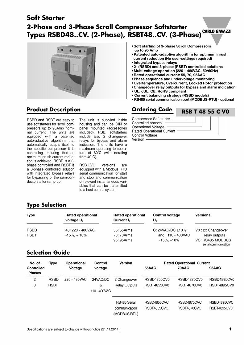
RSBD and RSBT are easy touse softstarters for scroll com-pressors up to 95Amp nomi-nal current. The units areequipped with a patentedauto-adaptive algorithm thatautomatically adapts itself tothe specific compressor it iscontrolling ensuring that anoptimum inrush current reduc-tion is achieved. RSBD is a 2-phase controlled and RSBT isa 3-phase controlled solutionwith integrated bypass relaysfor bypassing of the semicon-ductors after ramp-up.
The unit is supplied insidehousing and can be DIN orpanel mounted (accessoriesincluded). RSB. softstartersinclude also 2 changeoverrelays for bypass and alarmindication. The units have amaximum operating tempera-ture of 60˚C (with deratingfrom 40˚C).
RSB.CVC versions areequipped with a Modbus RTUserial communication for startand stop and communicationof relevant instantaneous vari-ables that can be transmittedto a host control system.
Compressor SoftstarterControlled phasesOperational VoltageRated Operational CurrentControl VoltageVersion
Type Selection
Type Rated operational Rated operational Control voltage Versionsvoltage Ue Current Ie Uc
RSBD 48: 220 - 480VAC 55: 55Arms C: 24VAC/DC ±10% V0 : 2x ChangeoverRSBT -15%, + 10% 70: 70Arms and 110 - 400VAC relay outputs
95: 95Arms -15%, +10% VC: RS485 MODBUSserial communication
No. of Type Operational Control Version Rated Operational CurrentControlled Voltage voltage 55AAC 70AAC 95AACPhases
2 RSBD 220 - 480VAC 24VAC/DC 2 Changeover RSBD4855CV0 RSBD4870CV0 RSBD4895CV0
3 RSBT & Relay Outputs RSBT4855CV0 RSBT4870CV0 RSBT4895CV0
110 - 400VAC
RS485Serial RSBD4855CVC RSBD4870CVC RSBD4895CVC
communication RSBT4855CVC RSBT4870CVC RSBT4895CVC
(MODBUSRTU)
Selection Guide
2 Specifications are subject to change without notice (21.11.2014)
RSBD48..CV. (2-Phase), RSBT48..CV. (3-Phase)
General Specifications
Starting method Current limit-auto adaptiveRamp-up time 1 secRamp-down time 0 secInitial Torque Initial torque will vary indirectly
through the variation of thecurrent limit through theauto-adaptive algorithm.
Undervoltage/OvervoltageprotectionUndervoltage RSBx48xx 175VACrms (+/- 5%)Overvoltage RSBx48xx 560VACrms (+/-5%)Recovery from Undervoltage 200VACrmsRecovery from Overvoltage 500VACrmsStatus Indication LEDsPower Supply ON Green LEDRecovery mode(alarm condition) Flashing Red LEDAlarm Red LEDForm Designation 1Vibration Acc. to IEC60068-2-26Frequency 1 2 [+3/ -0]Hz to 25Hz
displacement +/- 1.6mmFrequency 2 25Hz to 100Hz@ 2g (19.96m/s2)
RS485 Communication Specifications
Type Bi-directional (static anddynamic variables andparameters)
Functions Configuring the deviceStart/StopModifying set-point parametersMonitoring of measuredvariables
Connection 2-wires (to reduce the noise usea shielded cable and connectthe shield to GND terminal andto the ground at the same point.
Address Default: 11-247, selectable via software
Protocol MODBUS (RTU)
Factory defined data format Data bits "8", parity "none",stop bit "1"Selectable by software:Parity: None, Odd, Even
Baud Rate Default: 9.6k bits/sSelectable by software:4.8k, 9.6k, 19.2k, 38.4k
Insulation
RS485 port to power 1.9kV
RS485port to aux. relays 1.5kV
RS485 port to control 1.8kV
RS485 port to heatsink 0.5kV
Input Specifications (Control Input)
Control VoltageUc, A1-A21 24VAC/DC (-10%, +10%)
&110 - 400VAC (-15% / +10%)Max. Pick up Voltage(for 24VAC/DC input) 20.4VAC/DCDrop Out Voltage Min.(for 24VAC/DC input) 5VAC/DCControl Voltage RangeUc, A1-A2 (for 110 – 400VAC input) 93.5 - 440VACrmsRated AC frequency 50/60Hz +/- 10%Rated insulation voltage (Ui) 690VACDielectric strengthDielectric withstand voltageInput to Heatsink 3.5kVrmsRated impulse withstand volt. 6 kV (1.2/50µs)Min. Control input current 0.4mAMax. Control input current 5mAInput to output response time <300msIntegrated varistor Yes
* Note 1: For the Canadian application, the control terminals A1, A2 of the RSB.devices shall be supplied by a secondary circuit where power is limited by a trans-former, rectifier, voltage divider, or similar device that derives power from a primarycircuit, and where the short-circuit limit between conductors of the secondary cir-cuit or between conductors and ground is 1500 VA or less. The short-circuit volt
ampere limit is the product of the open circuit voltage and the short circuit ampere
Output Specifications
IEC rated operational current Ie(AC-53b) @ 40°CRSB.4855CV. 55 AACrmsRSB.4870CV. 70 AACrmsRSB.4895CV. 95 AACrms
Note: For higher operating temp derating is as follows.RSB.4855CV. (0.8% per °C)RSB.4870CV. (1.2% per °C)RSB.4895CV. (0.8% per °C) up to a maximum of 60°C
Overload cycle accordingto EN/IEC 60947-4-2 @ 40°Csurrounding temperatureRSB.4855CV. 55: AC-53b:3.5-1:299RSB.4870CV. 70: AC-53b:3.5-1:299RSB.4895CV. 95: AC-53b:3.5-1:299Max Number of starts per hour@ 40°C 12Minimum full load current 5 AACrms
Specifications are subject to change without notice (21.11.2014) 3
RSBD48..CV. (2-Phase), RSBT48..CV. (3-Phase)
Environmental Specifications
Operating temperature -20°C to +60°C(-4°F to +140°F)
Storage temperature -30°C to +85°C(-22°F to 185°F)
Relative humidity <95% non-condensing @ 40°CPollution Degree 3Degree of Protection IP20 – Housing
IP00 – Terminal blockInstallation Category IIIInstallation Altitude 1000m
Supply Specifications
Operational Voltage RangeL1-L3 187 – 528VACrms 50/60Hz
Supply current at standby <40mABlocking Voltage 1600VpRated AC Frequency 50/60Hz +/- 10%Rated insulation voltage 690Vrms, acc to EN60947-1Dielectric Strength 2kVrmsSupply to heatsink 2kVrmsRated impulse withstandvoltage 6kV (1.2/50µs)Integrated varistor Yes (across controlled phases)
Across L1 - L3
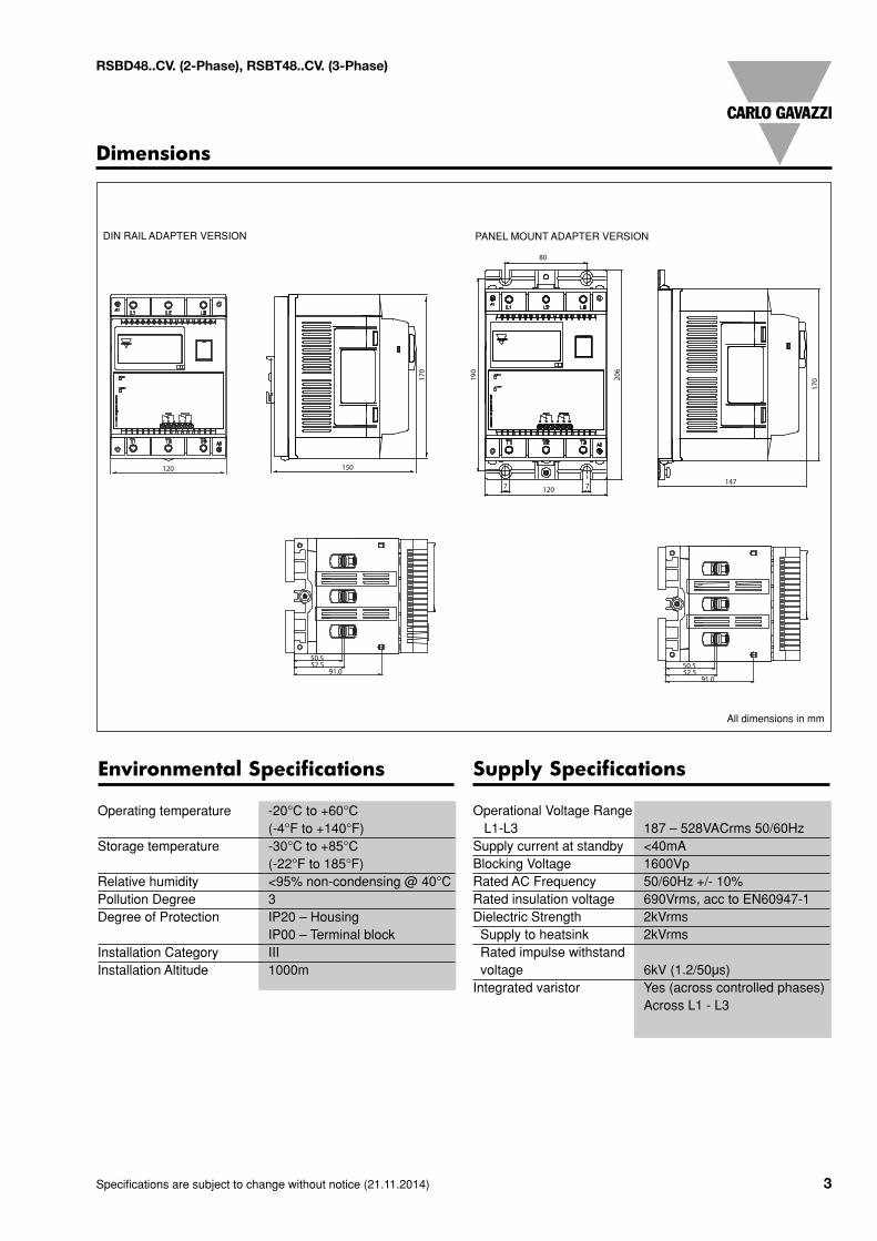
Dimensions
DIN RAIL ADAPTER VERSION SURFACE MOUNT ADAPTER VERSION
50.5
120 150
120
80
77 147
52.591.0
50.552.5
91.0
170
190
206
170
All dimensions in mm
DIN RAIL ADAPTER VERSION PANEL MOUNT ADAPTER VERSION
4 Specifications are subject to change without notice (21.11.2014)
RSBD48..CV. (2-Phase), RSBT48..CV. (3-Phase)
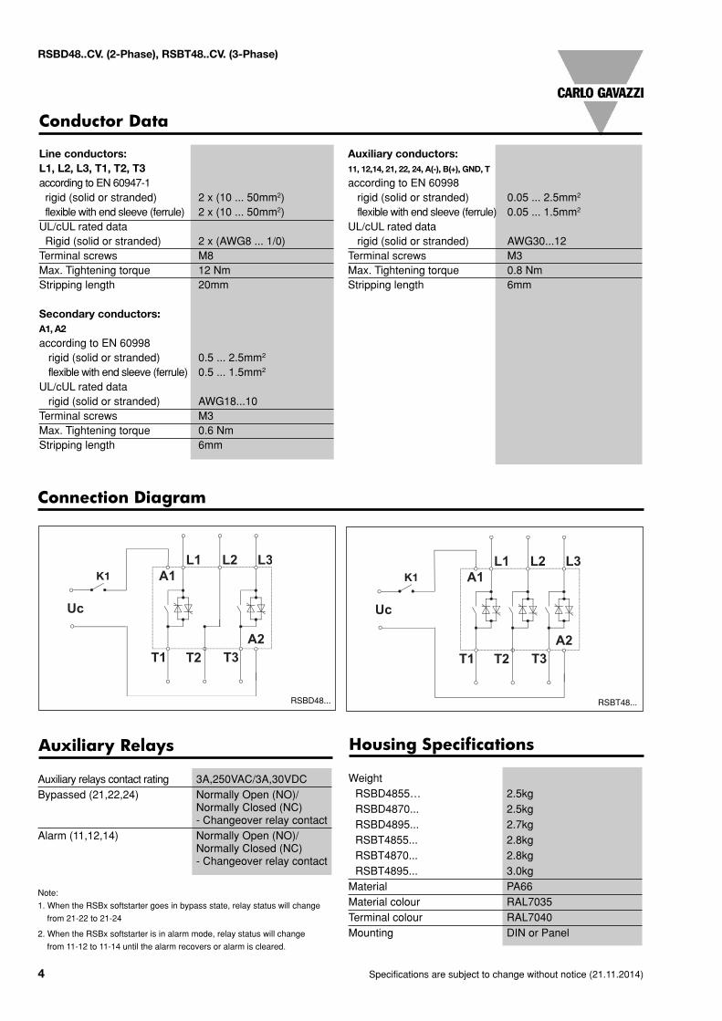
Housing Specifications
WeightRSBD4855… 2.5kgRSBD4870... 2.5kgRSBD4895... 2.7kgRSBT4855... 2.8kgRSBT4870... 2.8kgRSBT4895... 3.0kgMaterial PA66Material colour RAL7035Terminal colour RAL7040Mounting DIN or Panel
Auxiliary Relays
Auxiliary relays contact rating 3A,250VAC/3A,30VDCBypassed (21,22,24) Normally Open (NO)/
Normally Closed (NC)- Changeover relay contact
Alarm (11,12,14) Normally Open (NO)/Normally Closed (NC)- Changeover relay contact
Note:
1. When the RSBx softstarter goes in bypass state, relay status will change
from 21-22 to 21-24
2. When the RSBx softstarter is in alarm mode, relay status will change
from 11-12 to 11-14 until the alarm recovers or alarm is cleared.
Line conductors:L1, L2, L3, T1, T2, T3according to EN 60947-1rigid (solid or stranded) 2 x (10 ... 50mm2)flexible with end sleeve (ferrule) 2 x (10 ... 50mm2)UL/cUL rated dataRigid (solid or stranded) 2 x (AWG8 ... 1/0)Terminal screws M8Max. Tightening torque 12 NmStripping length 20mm
Secondary conductors:A1, A2
according to EN 60998rigid (solid or stranded) 0.5 ... 2.5mm2
flexible with end sleeve (ferrule) 0.5 ... 1.5mm2
UL/cUL rated datarigid (solid or stranded) AWG18...10
Terminal screws M3Max. Tightening torque 0.6 NmStripping length 6mm
Auxiliary conductors:11, 12,14, 21, 22, 24, A(-), B(+), GND, T
according to EN 60998rigid (solid or stranded) 0.05 ... 2.5mm2
flexible with end sleeve (ferrule) 0.05 ... 1.5mm2
UL/cUL rated datarigid (solid or stranded) AWG30...12
Terminal screws M3Max. Tightening torque 0.8 NmStripping length 6mm
Conductor Data
K1 K1
Connection Diagram
RSBT48...RSBD48...
Specifications are subject to change without notice (21.11.2014) 5
RSBD48..CV. (2-Phase), RSBT48..CV. (3-Phase)
Approvals
RSB...
M3~
M
Fuse
Contactor
Overload
I>>
RSB...
M3~
K
A1
A2
L1 L2 L3
T1 T2 T3
K1
M3 ~
A1
A2
L1 L2 L3
T1 T2 T3
M3 ~
~---
14
24
21
22
11
12
Alarm
Bypassed
14
24
21
22
11
12
Alarm
BypassedMotorProtectionRelay
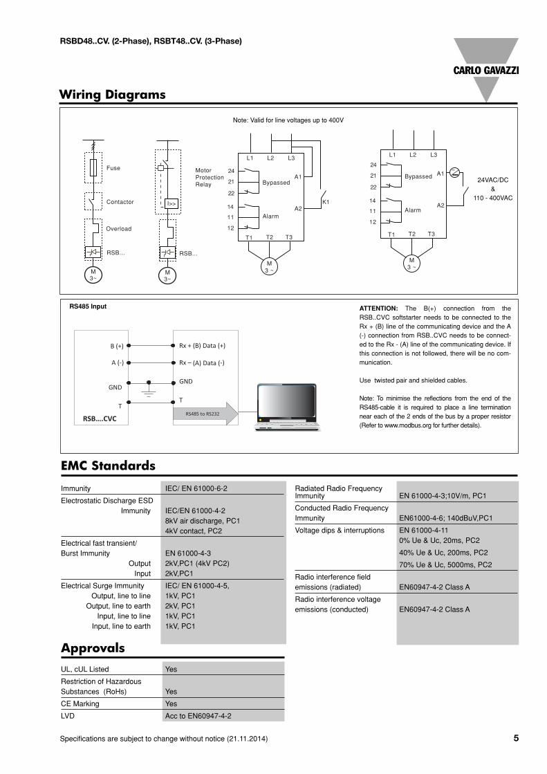
A (-)
B (+)
GND
T
Rx + (B) Data (+)
Rx – (A) Data (-)
GND
T
RS485 to RS232 PC RSB….CVC
Wiring Diagrams
Note: Valid for line voltages up to 400V
ATTENTION: The B(+) connection from theRSB..CVC softstarter needs to be connected to theRx + (B) line of the communicating device and the A(-) connection from RSB..CVC needs to be connect-ed to the Rx - (A) line of the communicating device. Ifthis connection is not followed, there will be no com-munication.
Use twisted pair and shielded cables.
Note: To minimise the reflections from the end of theRS485-cable it is required to place a line terminationnear each of the 2 ends of the bus by a proper resistor(Refer to www.modbus.org for further details).
RS485 Input
24VAC/DC&
110 - 400VAC
UL, cUL Listed Yes
Restriction of HazardousSubstances (RoHs) Yes
CE Marking Yes
LVD Acc to EN60947-4-2
EMC Standards
Immunity IEC/ EN 61000-6-2
Electrostatic Discharge ESDImmunity IEC/EN 61000-4-2
8kV air discharge, PC14kV contact, PC2
Electrical fast transient/Burst Immunity EN 61000-4-3
Output 2kV,PC1 (4kV PC2)Input 2kV,PC1
Electrical Surge Immunity IEC/ EN 61000-4-5,Output, line to line 1kV, PC1
Output, line to earth 2kV, PC1Input, line to line 1kV, PC1
Input, line to earth 1kV, PC1
Radiated Radio FrequencyImmunity EN 61000-4-3;10V/m, PC1
Conducted Radio FrequencyImmunity EN61000-4-6; 140dBuV,PC1
Voltage dips & interruptions EN 61000-4-110% Ue & Uc, 20ms, PC2
40% Ue & Uc, 200ms, PC2
70% Ue & Uc, 5000ms, PC2
Radio interference fieldemissions (radiated) EN60947-4-2 Class A
Radio interference voltageemissions (conducted) EN60947-4-2 Class A
6 Specifications are subject to change without notice (21.11.2014)
RSBD48..CV. (2-Phase), RSBT48..CV. (3-Phase)
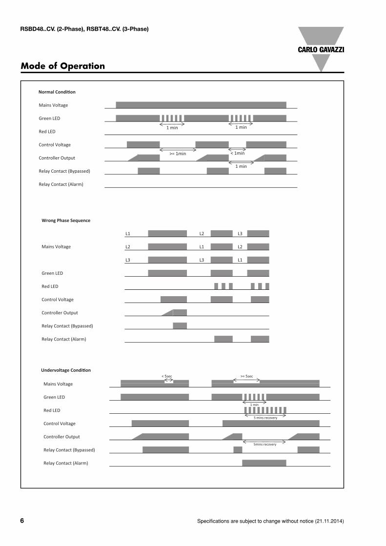
Mode of Operation
Normal Condi on
Mains Voltage
Green LED
Red LED
Control Voltage
Controller Output
Relay Contact (Bypassed)
Relay Contact (Alarm)
1 min
>= 1min < 1min
1 min 1 min
Wrong Phase Sequence
L1 L2
L2 L1
L3 L3
Green LED
Red LED
Control Voltage
Controller Output
Relay Contact (Bypassed)
Relay Contact (Alarm)
L3
L2
L1
Mains Voltage
Undervoltage Condi on
Green LED
Red LED
Control Voltage
Controller Output
Relay Contact (Bypassed)
Relay Contact (Alarm)
Mains Voltage
< 5sec >= 5sec
5 mins recovery
1 min
5mins recovery
Specifications are subject to change without notice (21.11.2014) 7
RSBD48..CV. (2-Phase), RSBT48..CV. (3-Phase)
Mode of Operation
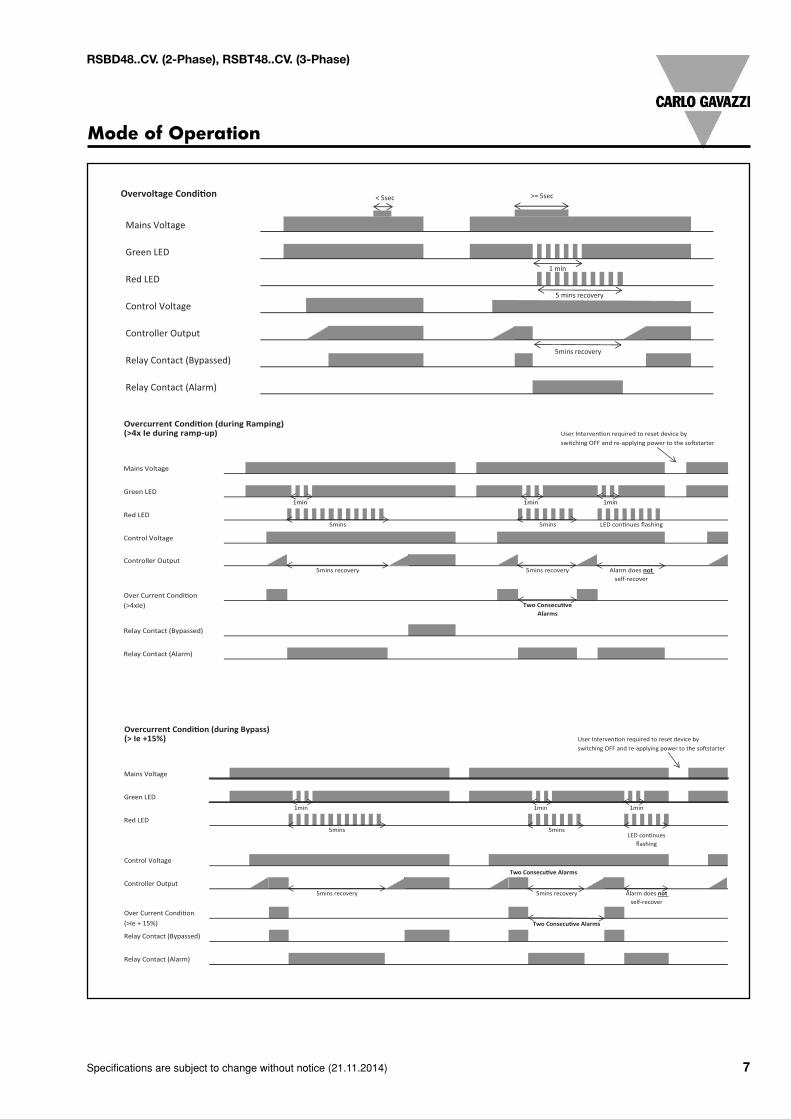
Overvoltage Condi on
Green LED
Red LED
Control Voltage
Controller Output
Relay Contact (Bypassed)
Relay Contact (Alarm)
5mins recovery
< 5sec >= 5sec
Mains Voltage
1 min
5 mins recovery
Overcurrent Condi on (during Ramping)(>4x Ie during ramp-up)
Green LED
Red LED
Control Voltage
Controller Output
Over Current Condi on(>4xIe)
Relay Contact (Bypassed)
Relay Contact (Alarm)
Two Consecu ve Alarms
1min
5mins
5mins recovery
1min
5mins
Alarm does notself-recover
Mains Voltage
switching OFF and re-applying power to the so starterUser Interven on required to reset device by
5mins recovery
LED con nues flashing
1min
Overcurrent Cond n (during Bypass)(> Ie +15%) User Interven on required to reset device by
switching OFF and re-applying power to the so starter
Green LED
Red LED
Control Voltage
Two Consecu ve Alarms
Controller Output
Over Current Condi on(>Ie + 15%)
Relay Contact (Bypassed)
Relay Contact (Alarm)
5mins
5mins recovery
Two Consecu ve Alarms
Alarm does not self-recover
LED con nues flashing
1min
Mains Voltage
1min
5mins
5mins recovery
1min
8 Specifications are subject to change without notice (21.11.2014)
RSBD48..CV. (2-Phase), RSBT48..CV. (3-Phase)
Mode of Operation
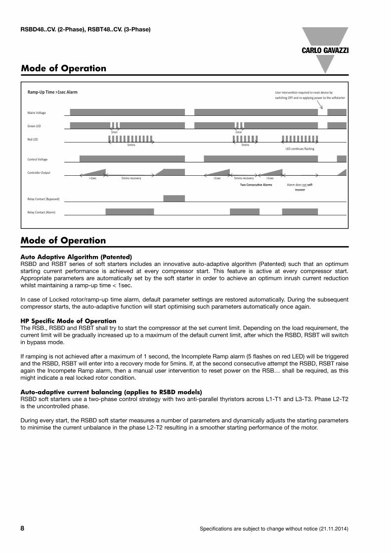
Ramp-Up Time >1sec Alarm User Interven on required to reset device byswitching OFF and re-applying power to the so starter
Green LED
Red LED
Control Voltage
Controller Output>1sec >1sec
Relay Contact (Bypassed)
Relay Contact (Alarm)
Mains Voltage
1min
5mins
5mins recovery
1min
5mins
5mins recovery >1sec
Two Consecu ve Alarms
LED con nues flashing
Alarm does not self-recover
Mode of Operation
Auto Adaptive Algorithm (Patented)RSBD and RSBT series of soft starters includes an innovative auto-adaptive algorithm (Patented) such that an optimumstarting current performance is achieved at every compressor start. This feature is active at every compressor start.Appropriate parameters are automatically set by the soft starter in order to achieve an optimum inrush current reductionwhilst maintaining a ramp-up time < 1sec.
In case of Locked rotor/ramp-up time alarm, default parameter settings are restored automatically. During the subsequentcompressor starts, the auto-adaptive function will start optimising such parameters automatically once again.
HP Specific Mode of OperationThe RSB., RSBD and RSBT shall try to start the compressor at the set current limit. Depending on the load requirement, thecurrent limit will be gradually increased up to a maximum of the default current limit, after which the RSBD, RSBT will switchin bypass mode.
If ramping is not achieved after a maximum of 1 second, the Incomplete Ramp alarm (5 flashes on red LED) will be triggeredand the RSBD, RSBT will enter into a recovery mode for 5mins. If, at the second consecutive attempt the RSBD, RSBT raiseagain the Incompete Ramp alarm, then a manual user intervention to reset power on the RSB… shall be required, as thismight indicate a real locked rotor condition.
Auto-adaptive current balancing (applies to RSBD models)RSBD soft starters use a two-phase control strategy with two anti-parallel thyristors across L1-T1 and L3-T3. Phase L2-T2is the uncontrolled phase.
During every start, the RSBD soft starter measures a number of parameters and dynamically adjusts the starting parametersto minimise the current unbalance in the phase L2-T2 resulting in a smoother starting performance of the motor.
Specifications are subject to change without notice (21.11.2014) 9
RSBD48..CV. (2-Phase), RSBT48..CV. (3-Phase)
Flashing Sequence
LED Status Indication
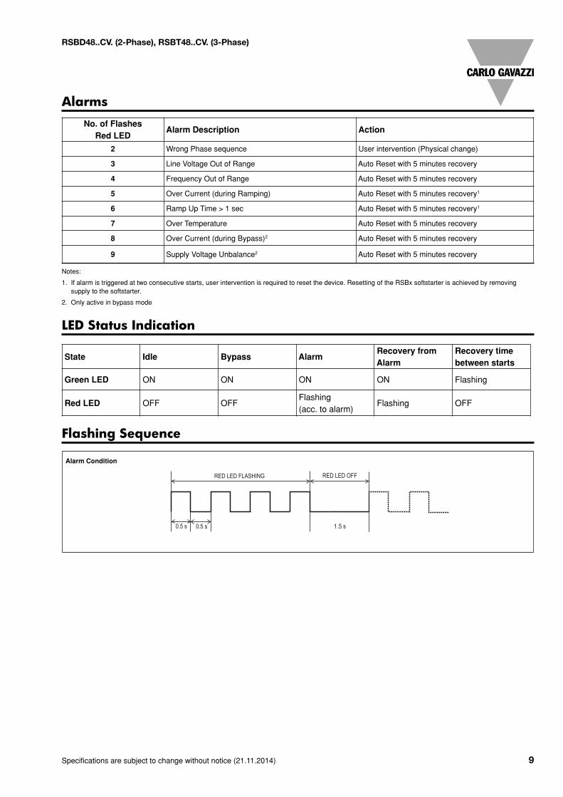
AlarmsNo. of Flashes
Red LEDAlarm Description Action
2 Wrong Phase sequence User intervention (Physical change)
3 Line Voltage Out of Range Auto Reset with 5 minutes recovery
4 Frequency Out of Range Auto Reset with 5 minutes recovery
5 Over Current (during Ramping) Auto Reset with 5 minutes recovery1
6 Ramp Up Time > 1 sec Auto Reset with 5 minutes recovery1
7 Over Temperature Auto Reset with 5 minutes recovery
8 Over Current (during Bypass)2 Auto Reset with 5 minutes recovery
9 Supply Voltage Unbalance2 Auto Reset with 5 minutes recovery
Notes:
1. If alarm is triggered at two consecutive starts, user intervention is required to reset the device. Resetting of the RSBx softstarter is achieved by removingsupply to the softstarter.
2. Only active in bypass mode
Alarm Condition
State Idle Bypass AlarmRecovery fromAlarm
Recovery timebetween starts
Green LED ON ON ON ON Flashing
Red LED OFF OFFFlashing(acc. to alarm)
Flashing OFF
10 Specifications are subject to change without notice (21.11.2014)
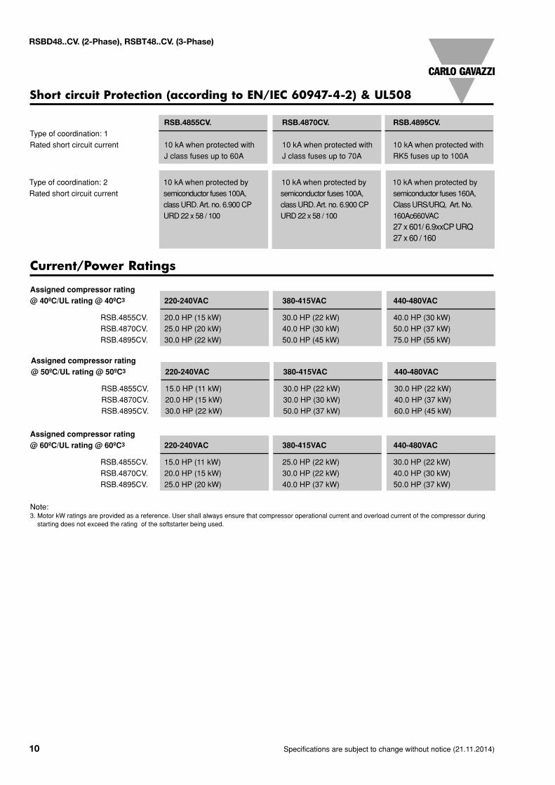
Short circuit Protection (according to EN/IEC 60947-4-2) & UL508
Current/Power Ratings
RSB.4855CV. RSB.4870CV. RSB.4895CV.Type of coordination: 1Rated short circuit current 10 kA when protected with 10 kA when protected with 10 kA when protected with
J class fuses up to 60A J class fuses up to 70A RK5 fuses up to 100A
Type of coordination: 2 10 kA when protected by 10 kA when protected by 10 kA when protected byRated short circuit current semiconductor fuses 100A, semiconductor fuses 100A, semiconductor fuses 160A,
classURD.Art. no. 6.900CP classURD.Art. no. 6.900CP ClassURS/URQ, Art. No.URD22 x 58 / 100 URD22 x 58 / 100 160Ac660VAC
27 x 601/ 6.9xxCPURQ27 x 60 / 160
Assigned compressor rating@ 40ºC/UL rating @ 40ºC3 220-240VAC 380-415VAC 440-480VAC
RSB.4855CV. 20.0 HP (15 kW) 30.0 HP (22 kW) 40.0 HP (30 kW)RSB.4870CV. 25.0 HP (20 kW) 40.0 HP (30 kW) 50.0 HP (37 kW)RSB.4895CV. 30.0 HP (22 kW) 50.0 HP (45 kW) 75.0 HP (55 kW)
RSBD48..CV. (2-Phase), RSBT48..CV. (3-Phase)
Assigned compressor rating@ 50ºC/UL rating @ 50ºC3 220-240VAC 380-415VAC 440-480VAC
RSB.4855CV. 15.0 HP (11 kW) 30.0 HP (22 kW) 30.0 HP (22 kW)RSB.4870CV. 20.0 HP (15 kW) 30.0 HP (30 kW) 40.0 HP (37 kW)RSB.4895CV. 30.0 HP (22 kW) 50.0 HP (37 kW) 60.0 HP (45 kW)
Assigned compressor rating@ 60ºC/UL rating @ 60ºC3 220-240VAC 380-415VAC 440-480VAC
RSB.4855CV. 15.0 HP (11 kW) 25.0 HP (22 kW) 30.0 HP (22 kW)RSB.4870CV. 20.0 HP (15 kW) 30.0 HP (22 kW) 40.0 HP (30 kW)RSB.4895CV. 25.0 HP (20 kW) 40.0 HP (37 kW) 50.0 HP (37 kW)
Note:3. Motor kW ratings are provided as a reference. User shall always ensure that compressor operational current and overload current of the compressor duringstarting does not exceed the rating of the softstarter being used.
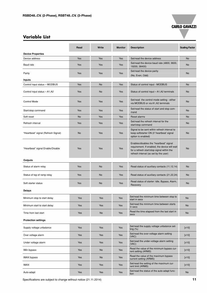
Delays
Minimum stop to start delay Yes Yes Yes Set/read the minimum time between stop tostart in secs No
Minimum start to start delay Yes Yes Yes Set/read the minimum time between startsin secs No
Time from last start Yes No Yes Read the time elapsed from the last start insecs No
Protection settings
Supply voltage unbalance Yes Yes Yes Set/read the supply voltage unbalance set-ting (%) [x10]
Over voltage alarm Yes Yes Yes Set/read the over-voltage alarm setting(VAC) [x10]
Under voltage alarm Yes Yes Yes Set/read the under-voltage alarm setting(VAC) [x10]
IMin bypass Yes No Yes Read the value of the minimum bypass cur-rent setting (ARMS) [x10]
IMAX bypass Yes No Yes Read the value of the maximum bypasscurrent setting (ARMS) [x10]
IMAX Yes Yes Yes Set/read the setting of the maximum cur-rent limit (ARMS) [x10]
Auto-adapt Yes Yes Yes Set/read the status of the auto-adapt func-tion No
Specifications are subject to change without notice (21.11.2014) 11
Variable List
RSBD48..CV. (2-Phase), RSBT48..CV. (3-Phase)
Read Write Monitor Description ScalingFactor
Device Properties
Device address Yes Yes Yes Set/read the device address No
Baud rate Yes Yes YesSet/read the device baud rate (4800, 9600,19200, 38400)
No
Parity Yes Yes YesSet/read the device parity
No(No, Even, Odd)
Inputs
Control input status – MODBUS Yes No Yes Status of control input - MODBUS No
Control input status – A1,A2 Yes No Yes Status of control input – A1,A2 terminals No
Control Mode Yes Yes YesSet/read the control mode setting - eithervia MODBUS or via A1,A2 terminals
No
Start/stop command Yes Yes YesSet/read the status of start and stop com-mand
No
Soft reset No Yes Yes Reset alarms No
Refresh interval Yes Yes YesSet/read the refresh interval for thestart/stop command
No
“Heartbeat” signal (Refresh Signal) No Yes YesSignal to be sent within refresh interval tokeep softstarter ON (if ‘heartbeat’ signaloption is enabled)
No
“Heartbeat” signal Enable/Disable Yes Yes Yes
Enables/disables the “heartbeat” signalrequirement. If enabled, the device will waitfor a refresh start/stop signal within therefresh interval (as set by the user)
No
Outputs
Status of alarm relay Yes No Yes Read status of auxiliary contacts (11,12,14) No
Status of top of ramp relay Yes No Yes Read status of auxiliary contacts (21,22,24) No
Soft starter status Yes No YesRead status of starter: Idle, Bypass, Alarm,Recovery
No
12 Specifications are subject to change without notice (21.11.2014)
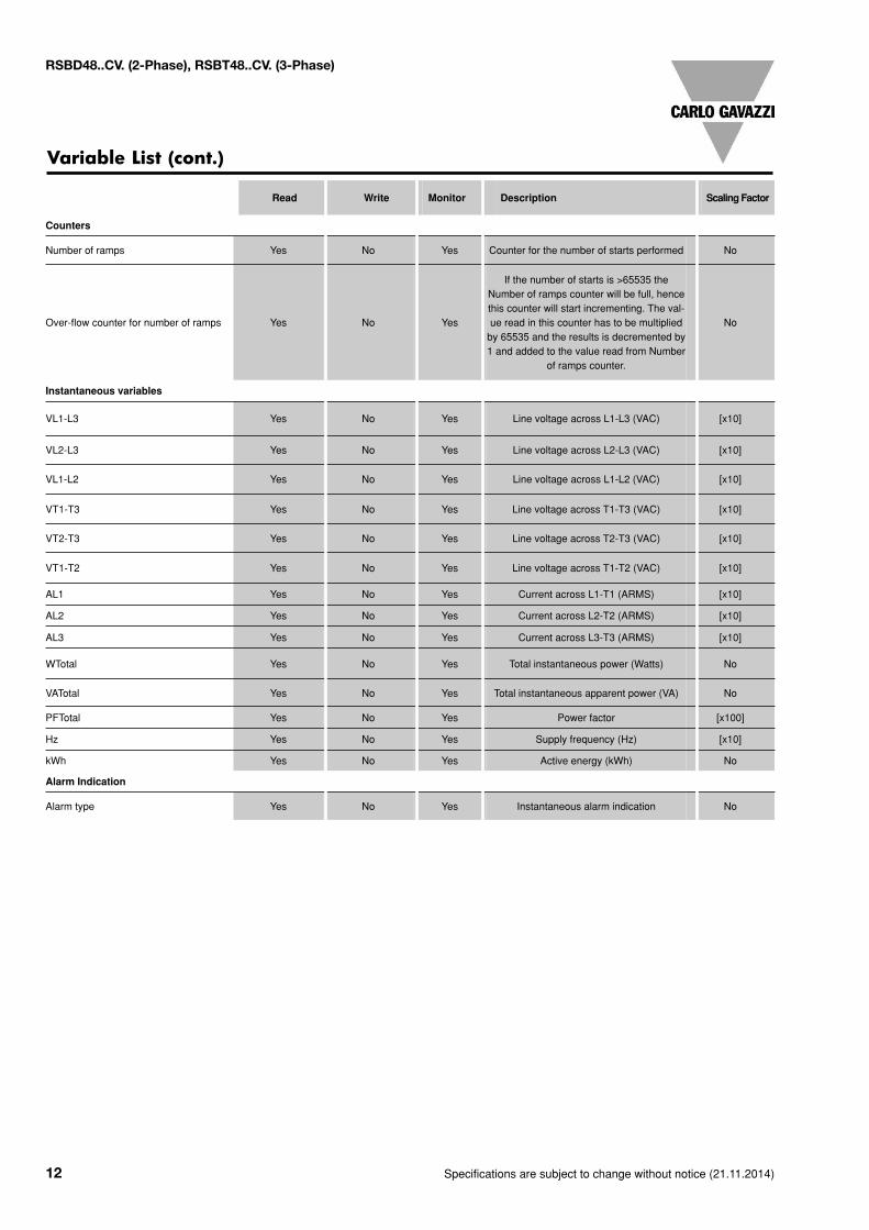
Variable List (cont.)
RSBD48..CV. (2-Phase), RSBT48..CV. (3-Phase)
Counters
Number of ramps Yes No Yes Counter for the number of starts performed No
Over-flow counter for number of ramps Yes No Yes
If the number of starts is >65535 theNumber of ramps counter will be full, hencethis counter will start incrementing. The val-ue read in this counter has to be multipliedby 65535 and the results is decremented by1 and added to the value read from Number
of ramps counter.
No
Instantaneous variables
VL1-L3 Yes No Yes Line voltage across L1-L3 (VAC) [x10]
VL2-L3 Yes No Yes Line voltage across L2-L3 (VAC) [x10]
VL1-L2 Yes No Yes Line voltage across L1-L2 (VAC) [x10]
VT1-T3 Yes No Yes Line voltage across T1-T3 (VAC) [x10]
VT2-T3 Yes No Yes Line voltage across T2-T3 (VAC) [x10]
VT1-T2 Yes No Yes Line voltage across T1-T2 (VAC) [x10]
AL1 Yes No Yes Current across L1-T1 (ARMS) [x10]
AL2 Yes No Yes Current across L2-T2 (ARMS) [x10]
AL3 Yes No Yes Current across L3-T3 (ARMS) [x10]
WTotal Yes No Yes Total instantaneous power (Watts) No
VATotal Yes No Yes Total instantaneous apparent power (VA) No
PFTotal Yes No Yes Power factor [x100]
Hz Yes No Yes Supply frequency (Hz) [x10]
kWh Yes No Yes Active energy (kWh) No
Alarm Indication
Alarm type Yes No Yes Instantaneous alarm indication No
Read Write Monitor Description ScalingFactor