Embed Size (px)
Citation preview

Table of ContentsImportant Notes
Introduction 1Configuration Instructions 2Installation, Connection and Branch Layout
3
Display, Controls and Device Interfaces
4
Commissioning 5Device Functions 6Diagnosis and Messages 7Communication Module PROFIBUS DP
8
Circuit Examples 9General Technical Data 10Appendix
Configuration Data
Index
Correction Sheet
SIRIUS
Issue 04/2009GWA 4NEB 535 2195-02 DS 05
Order No.: 3ZX1012-0RW44-1AC1
Soft Starter3RW44
System Manual


Safety Guidelines This manual contains notices you have to observe in order to guarantee your personal safety, as well as to prevent damage to property. The notices referring to your personal safety are highlighted in the manual by a safety alert symbol, notices referring only to property damage have no safety alert symbol. These notices shown below are graded according to the degree of danger.
Dangerindicates that death or severe personal injury will result if proper precautions are not taken.
Warningindicates that death or severe personal injury may result if proper precautions are not taken.
Cautionwith a safety alert symbol, indicates that minor personal injury can result if proper precautions are not taken.
Cautionwithout a safety alert symbol, indicates that property damage can result if proper precautions are not taken.
Noticeindicates that an unintended result or situation can occur if the corresponding information is not taken into account.
If more than one degree of danger is present, the warning notice representing the highest degree of danger will be used. A notice warning of injury to persons with a safety alert symbol may also include a warning relating to property damage.
Qualified personnelThe device/system may only be set up and used in conjunction with this documentation. Commissioning and operation of a device/system may only be performed by qualified personnel. Within the context of the safety notes in this documentation qualified persons are defined as persons who are authorized to commission, ground and label devices, systems and circuits in accordance with established safety practices and standards.
Prescribed UsageNote the following:
WarningThe device may only be used for the applications described in the catalog or the technical description and only in connection with devices or components from other manufacturers which have been approved or recommended by Siemens. Correct, reliable operation of the product requires proper transport, storage, positioning and assembly as well as careful operation and maintenance.
TrademarksAll names identified by ® are registered trademarks of the Siemens AG. The remaining trademarks in this publication may be trademarks whose use by third parties for their own purposes could violate the rights of the owner.
Siemens AGAutomation & DrivesP.O. box 4848, 90327 Nuremberg, Germany
Siemens Aktiengesellschaft
© Siemens AG 2005Subject to technical changes
Copyright Siemens AG 2005. All rights reserved.
This document shall not be transmitted or reproduced, nor shall its contents be exploited or disclosed to third persons without prior written consent from Siemens. Infringements will be subject to damage claims. All rights reserved, in particular in case of a patent grant of utility model registration.
Disclaimer of liability
Although we have carefully checked the contents of this publication forconformity with the hardware and software described, we cannotguarantee complete conformity since errors cannot be excluded. Theinformation provided in this manual is checked at regular intervals andany corrections which might become necessary will be included in thenext editions.

Table of Contents
Table of Contents
Important Notes . . . . . . . . . . . . . . . . . . . . . . . . . . . . . . . . . . . . . . . . . . . . . . . . . . . . . . . . . . . . . . . . vii
1 Introduction . . . . . . . . . . . . . . . . . . . . . . . . . . . . . . . . . . . . . . . . . . . . . . . . . . . . . . . . . . . . . . . . . . 1-1
1.1 Physical Basics of the 3-phase Asynchronous Motor and Mode of Operation of the Soft Starter . 1-21.1.1 3-phase Asynchronous Motor . . . . . . . . . . . . . . . . . . . . . . . . . . . . . . . . . . . . . . . . . . . . . . . . . . . . . 1-21.1.2 Operating Mode of the SIRIUS 3RW44 Electronic Soft Starter . . . . . . . . . . . . . . . . . . . . . . . . . . . . 1-41.2 Application and Use . . . . . . . . . . . . . . . . . . . . . . . . . . . . . . . . . . . . . . . . . . . . . . . . . . . . . . . . . . . . 1-71.3 Marginal Conditions for Storage and Operation . . . . . . . . . . . . . . . . . . . . . . . . . . . . . . . . . . . . . . . 1-8
2 Configuration Instructions . . . . . . . . . . . . . . . . . . . . . . . . . . . . . . . . . . . . . . . . . . . . . . . . . . . . . . 2-1
2.1 Configuration . . . . . . . . . . . . . . . . . . . . . . . . . . . . . . . . . . . . . . . . . . . . . . . . . . . . . . . . . . . . . . . . . . 2-22.1.1 RS 232 Serial PC Interface and Soft Starter ES Parameterization and Operating Software. . . . . . 2-22.1.2 Win Soft Starter Selection and Simulation Program . . . . . . . . . . . . . . . . . . . . . . . . . . . . . . . . . . . . 2-22.1.3 Training Course for SIRIUS Soft Starters (SD-SIRIUSO) . . . . . . . . . . . . . . . . . . . . . . . . . . . . . . . . 2-22.2 Normal or Heavy Starting . . . . . . . . . . . . . . . . . . . . . . . . . . . . . . . . . . . . . . . . . . . . . . . . . . . . . . . . 2-32.2.1 Application Examples for Normal Starting (CLASS 10) . . . . . . . . . . . . . . . . . . . . . . . . . . . . . . . . . . 2-32.2.2 Application Examples for Heavy Starting (CLASS 20). . . . . . . . . . . . . . . . . . . . . . . . . . . . . . . . . . . 2-32.2.3 Application Examples for Very Heavy Starting (CLASS 30) . . . . . . . . . . . . . . . . . . . . . . . . . . . . . . 2-42.3 On-time and Switching Frequency . . . . . . . . . . . . . . . . . . . . . . . . . . . . . . . . . . . . . . . . . . . . . . . . . 2-52.4 Installation Altitude and Ambient Temperature . . . . . . . . . . . . . . . . . . . . . . . . . . . . . . . . . . . . . . . . 2-62.5 Basic Factory Settings . . . . . . . . . . . . . . . . . . . . . . . . . . . . . . . . . . . . . . . . . . . . . . . . . . . . . . . . . . 2-72.6 Order Number Classification for SIRIUS 3RW44 Soft Starters . . . . . . . . . . . . . . . . . . . . . . . . . . . . 2-8
3 Installation, Connection and Branch Layout . . . . . . . . . . . . . . . . . . . . . . . . . . . . . . . . . . . . . . . 3-1
3.1 Installing the Soft Starter . . . . . . . . . . . . . . . . . . . . . . . . . . . . . . . . . . . . . . . . . . . . . . . . . . . . . . . . . 3-23.1.1 Unpacking . . . . . . . . . . . . . . . . . . . . . . . . . . . . . . . . . . . . . . . . . . . . . . . . . . . . . . . . . . . . . . . . . . . . 3-23.1.2 Mounting Position. . . . . . . . . . . . . . . . . . . . . . . . . . . . . . . . . . . . . . . . . . . . . . . . . . . . . . . . . . . . . . . 3-23.1.3 Standards. . . . . . . . . . . . . . . . . . . . . . . . . . . . . . . . . . . . . . . . . . . . . . . . . . . . . . . . . . . . . . . . . . . . . 3-23.1.4 Mounting Dimensions and Clearances . . . . . . . . . . . . . . . . . . . . . . . . . . . . . . . . . . . . . . . . . . . . . . 3-33.2 Branch Layout . . . . . . . . . . . . . . . . . . . . . . . . . . . . . . . . . . . . . . . . . . . . . . . . . . . . . . . . . . . . . . . . . 3-43.2.1 General . . . . . . . . . . . . . . . . . . . . . . . . . . . . . . . . . . . . . . . . . . . . . . . . . . . . . . . . . . . . . . . . . . . . . . 3-43.2.2 Soft Starters in Standard Circuits. . . . . . . . . . . . . . . . . . . . . . . . . . . . . . . . . . . . . . . . . . . . . . . . . . . 3-53.2.3 Soft Starters in Inside Delta Circuits . . . . . . . . . . . . . . . . . . . . . . . . . . . . . . . . . . . . . . . . . . . . . . . . 3-63.2.4 Soft Starter with Contactor Disconnector (Main Contactor) . . . . . . . . . . . . . . . . . . . . . . . . . . . . . . . 3-83.3 Protection of the Soft Starter against Short-Circuits . . . . . . . . . . . . . . . . . . . . . . . . . . . . . . . . . . . . 3-93.4 Capacitors for Power Factor Improvement . . . . . . . . . . . . . . . . . . . . . . . . . . . . . . . . . . . . . . . . . . 3-103.5 3RW44 in Generator Operation (with 3-Phase Asynchronous Motor) . . . . . . . . . . . . . . . . . . . . . 3-103.6 Electrical Connection . . . . . . . . . . . . . . . . . . . . . . . . . . . . . . . . . . . . . . . . . . . . . . . . . . . . . . . . . . 3-103.6.1 Control and Auxiliary Current Connection . . . . . . . . . . . . . . . . . . . . . . . . . . . . . . . . . . . . . . . . . . . 3-103.6.2 Main Current Connection . . . . . . . . . . . . . . . . . . . . . . . . . . . . . . . . . . . . . . . . . . . . . . . . . . . . . . . . 3-113.6.3 Conductor Cross-Sections . . . . . . . . . . . . . . . . . . . . . . . . . . . . . . . . . . . . . . . . . . . . . . . . . . . . . . . 3-12
4 Display, Controls and Device Interfaces . . . . . . . . . . . . . . . . . . . . . . . . . . . . . . . . . . . . . . . . . . . 4-1
4.1 Display and Controls . . . . . . . . . . . . . . . . . . . . . . . . . . . . . . . . . . . . . . . . . . . . . . . . . . . . . . . . . . . . 4-24.2 Device Interfaces . . . . . . . . . . . . . . . . . . . . . . . . . . . . . . . . . . . . . . . . . . . . . . . . . . . . . . . . . . . . . . 4-34.2.1 Local Device Interface . . . . . . . . . . . . . . . . . . . . . . . . . . . . . . . . . . . . . . . . . . . . . . . . . . . . . . . . . . . 4-34.2.2 PROFIBUS Interface (Optional) . . . . . . . . . . . . . . . . . . . . . . . . . . . . . . . . . . . . . . . . . . . . . . . . . . . . 4-34.3 External Display and Control Unit (Optional) . . . . . . . . . . . . . . . . . . . . . . . . . . . . . . . . . . . . . . . . . 4-3
SIRIUS 3RW44 system manual iGWA 4NEB 535 2195-02 DS 05

Table of Contents
5 Commissioning . . . . . . . . . . . . . . . . . . . . . . . . . . . . . . . . . . . . . . . . . . . . . . . . . . . . . . . . . . . . . . . 5-1
5.1 Menu Structure, Navigation, Changing Parameters . . . . . . . . . . . . . . . . . . . . . . . . . . . . . . . . . . . . 5-25.1.1 Menu Structure and Navigation . . . . . . . . . . . . . . . . . . . . . . . . . . . . . . . . . . . . . . . . . . . . . . . . . . . . 5-25.1.2 Changing Parameters: For Example Motor Data . . . . . . . . . . . . . . . . . . . . . . . . . . . . . . . . . . . . . . . 5-35.2 Switching on for the First Time . . . . . . . . . . . . . . . . . . . . . . . . . . . . . . . . . . . . . . . . . . . . . . . . . . . . 5-45.2.1 Recommendation on Procedure for 3RW44 Commissioning. . . . . . . . . . . . . . . . . . . . . . . . . . . . . . 5-45.2.2 Quick Start Menu . . . . . . . . . . . . . . . . . . . . . . . . . . . . . . . . . . . . . . . . . . . . . . . . . . . . . . . . . . . . . . . 5-65.3 User-specific Commissioning . . . . . . . . . . . . . . . . . . . . . . . . . . . . . . . . . . . . . . . . . . . . . . . . . . . . . 5-85.3.1 Main Menu Item "Settings" . . . . . . . . . . . . . . . . . . . . . . . . . . . . . . . . . . . . . . . . . . . . . . . . . . . . . . . 5-95.4 Making Settings in the Selected Parameter Set . . . . . . . . . . . . . . . . . . . . . . . . . . . . . . . . . . . . . . 5-105.4.1 Selecting the Parameter Set . . . . . . . . . . . . . . . . . . . . . . . . . . . . . . . . . . . . . . . . . . . . . . . . . . . . . 5-105.4.2 Entering the Motor Data . . . . . . . . . . . . . . . . . . . . . . . . . . . . . . . . . . . . . . . . . . . . . . . . . . . . . . . . . 5-115.4.3 Specifying the Starting Mode . . . . . . . . . . . . . . . . . . . . . . . . . . . . . . . . . . . . . . . . . . . . . . . . . . . . . 5-135.4.4 Specifying the Stopping Mode . . . . . . . . . . . . . . . . . . . . . . . . . . . . . . . . . . . . . . . . . . . . . . . . . . . . 5-205.4.5 Setting Slow Speed Parameters . . . . . . . . . . . . . . . . . . . . . . . . . . . . . . . . . . . . . . . . . . . . . . . . . . 5-265.4.6 Specifying Current Limit Values . . . . . . . . . . . . . . . . . . . . . . . . . . . . . . . . . . . . . . . . . . . . . . . . . . . 5-275.4.7 Parameterizing the Inputs . . . . . . . . . . . . . . . . . . . . . . . . . . . . . . . . . . . . . . . . . . . . . . . . . . . . . . . 5-285.4.8 Parameterizing the Outputs . . . . . . . . . . . . . . . . . . . . . . . . . . . . . . . . . . . . . . . . . . . . . . . . . . . . . . 5-295.4.9 Selecting Motor Protection Settings . . . . . . . . . . . . . . . . . . . . . . . . . . . . . . . . . . . . . . . . . . . . . . . . 5-315.4.10 Selecting Display Settings . . . . . . . . . . . . . . . . . . . . . . . . . . . . . . . . . . . . . . . . . . . . . . . . . . . . . . . 5-335.4.11 Specifying the Behavior of the Protective Functions . . . . . . . . . . . . . . . . . . . . . . . . . . . . . . . . . . . 5-345.4.12 Specifying the Names on the Device Display. . . . . . . . . . . . . . . . . . . . . . . . . . . . . . . . . . . . . . . . . 5-355.4.13 Activating the Field Bus Interface (PROFIBUS DP) . . . . . . . . . . . . . . . . . . . . . . . . . . . . . . . . . . . . 5-365.4.14 Saving Options . . . . . . . . . . . . . . . . . . . . . . . . . . . . . . . . . . . . . . . . . . . . . . . . . . . . . . . . . . . . . . . . 5-375.5 Other Device Functions . . . . . . . . . . . . . . . . . . . . . . . . . . . . . . . . . . . . . . . . . . . . . . . . . . . . . . . . . 5-415.5.1 Display measured value . . . . . . . . . . . . . . . . . . . . . . . . . . . . . . . . . . . . . . . . . . . . . . . . . . . . . . . . . 5-415.5.2 Status Display . . . . . . . . . . . . . . . . . . . . . . . . . . . . . . . . . . . . . . . . . . . . . . . . . . . . . . . . . . . . . . . . 5-425.5.3 Motor Control (Assigning Control Priority) . . . . . . . . . . . . . . . . . . . . . . . . . . . . . . . . . . . . . . . . . . . 5-435.5.4 Statistics . . . . . . . . . . . . . . . . . . . . . . . . . . . . . . . . . . . . . . . . . . . . . . . . . . . . . . . . . . . . . . . . . . . . . 5-445.5.5 Safety (Specifying the User Level, Parameterization Protection). . . . . . . . . . . . . . . . . . . . . . . . . . 5-48
6 Device Functions . . . . . . . . . . . . . . . . . . . . . . . . . . . . . . . . . . . . . . . . . . . . . . . . . . . . . . . . . . . . . . 6-1
6.1 Various Parameter Sets . . . . . . . . . . . . . . . . . . . . . . . . . . . . . . . . . . . . . . . . . . . . . . . . . . . . . . . . . 6-26.2 Starting Modes . . . . . . . . . . . . . . . . . . . . . . . . . . . . . . . . . . . . . . . . . . . . . . . . . . . . . . . . . . . . . . . . 6-36.2.1 Voltage Ramp. . . . . . . . . . . . . . . . . . . . . . . . . . . . . . . . . . . . . . . . . . . . . . . . . . . . . . . . . . . . . . . . . . 6-36.2.2 Torque Control . . . . . . . . . . . . . . . . . . . . . . . . . . . . . . . . . . . . . . . . . . . . . . . . . . . . . . . . . . . . . . . . . 6-56.2.3 Breakaway Pulse in Combination with the Voltage Ramp or Torque Control Starting Mode. . . . . . 6-76.2.4 Current Limiting in Combination with the Voltage Ramp or Torque Control Starting Mode . . . . . . . 6-96.2.5 Starting Mode: Direct On Line . . . . . . . . . . . . . . . . . . . . . . . . . . . . . . . . . . . . . . . . . . . . . . . . . . . . 6-106.2.6 Starting Mode: Motor Heating . . . . . . . . . . . . . . . . . . . . . . . . . . . . . . . . . . . . . . . . . . . . . . . . . . . . 6-106.3 Stopping Modes . . . . . . . . . . . . . . . . . . . . . . . . . . . . . . . . . . . . . . . . . . . . . . . . . . . . . . . . . . . . . . 6-116.3.1 Coasting Down . . . . . . . . . . . . . . . . . . . . . . . . . . . . . . . . . . . . . . . . . . . . . . . . . . . . . . . . . . . . . . . . 6-116.3.2 Torque Control and Pump Stop . . . . . . . . . . . . . . . . . . . . . . . . . . . . . . . . . . . . . . . . . . . . . . . . . . . 6-126.3.3 DC Braking / Combined Braking . . . . . . . . . . . . . . . . . . . . . . . . . . . . . . . . . . . . . . . . . . . . . . . . . . 6-136.4 Slow Speed Function . . . . . . . . . . . . . . . . . . . . . . . . . . . . . . . . . . . . . . . . . . . . . . . . . . . . . . . . . . 6-166.5 Current Limit Values for Load Monitoring . . . . . . . . . . . . . . . . . . . . . . . . . . . . . . . . . . . . . . . . . . . 6-186.6 Motor Protection Functions . . . . . . . . . . . . . . . . . . . . . . . . . . . . . . . . . . . . . . . . . . . . . . . . . . . . . . 6-196.7 Inherent Protection . . . . . . . . . . . . . . . . . . . . . . . . . . . . . . . . . . . . . . . . . . . . . . . . . . . . . . . . . . . . 6-23
7 Diagnosis and Messages . . . . . . . . . . . . . . . . . . . . . . . . . . . . . . . . . . . . . . . . . . . . . . . . . . . . . . . 7-1
7.1 Diagnosis, Messages . . . . . . . . . . . . . . . . . . . . . . . . . . . . . . . . . . . . . . . . . . . . . . . . . . . . . . . . . . . 7-27.1.1 Status Messages . . . . . . . . . . . . . . . . . . . . . . . . . . . . . . . . . . . . . . . . . . . . . . . . . . . . . . . . . . . . . . . 7-27.1.2 Warnings and Group Errors . . . . . . . . . . . . . . . . . . . . . . . . . . . . . . . . . . . . . . . . . . . . . . . . . . . . . . . 7-2
ii SIRIUS 3RW44 system manualGWA 4NEB 535 2195-02 DS 05

Table of Contents
7.1.3 Device Errors . . . . . . . . . . . . . . . . . . . . . . . . . . . . . . . . . . . . . . . . . . . . . . . . . . . . . . . . . . . . . . . . . . 7-7
8 PROFIBUS DP Communication Module . . . . . . . . . . . . . . . . . . . . . . . . . . . . . . . . . . . . . . . . . . . 8-1
8.1 Introduction . . . . . . . . . . . . . . . . . . . . . . . . . . . . . . . . . . . . . . . . . . . . . . . . . . . . . . . . . . . . . . . . . . . 8-48.1.1 Definitions . . . . . . . . . . . . . . . . . . . . . . . . . . . . . . . . . . . . . . . . . . . . . . . . . . . . . . . . . . . . . . . . . . . . 8-58.2 Data Transmission . . . . . . . . . . . . . . . . . . . . . . . . . . . . . . . . . . . . . . . . . . . . . . . . . . . . . . . . . . . . . 8-68.2.1 Data Transmission Options . . . . . . . . . . . . . . . . . . . . . . . . . . . . . . . . . . . . . . . . . . . . . . . . . . . . . . . 8-68.2.2 Communication Principle . . . . . . . . . . . . . . . . . . . . . . . . . . . . . . . . . . . . . . . . . . . . . . . . . . . . . . . . . 8-68.3 Installation of the PROFIBUS DP Communication Module . . . . . . . . . . . . . . . . . . . . . . . . . . . . . . . 8-78.3.1 Insertion of the PROFIBUS DP Communication Module (Field Bus Interface) . . . . . . . . . . . . . . . . 8-78.4 Activating the PROFIBUS DP Communication Module (Field Bus Interface) and Setting the
Station Address . . . . . . . . . . . . . . . . . . . . . . . . . . . . . . . . . . . . . . . . . . . . . . . . . . . . . . . . . . . . . . . . 8-98.4.1 Introduction . . . . . . . . . . . . . . . . . . . . . . . . . . . . . . . . . . . . . . . . . . . . . . . . . . . . . . . . . . . . . . . . . . . 8-98.4.2 Activating the PROFIBUS DP Communication Module via the Display, Setting the Station
Address and Saving the Settings . . . . . . . . . . . . . . . . . . . . . . . . . . . . . . . . . . . . . . . . . . . . . . . . . . 8-108.4.3 Activating the PROFIBUS DP Communication Module (Field Bus Interface) and Setting the
Station Address via the Device Interface using the "Soft Starter ES Premium" or the "Soft Starter ES + SP1" Software. . . . . . . . . . . . . . . . . . . . . . . . . . . . . . . . . . . . . . . . . . . . . . . . . . 8-13
8.5 Soft Starter Configuration . . . . . . . . . . . . . . . . . . . . . . . . . . . . . . . . . . . . . . . . . . . . . . . . . . . . . . . 8-158.5.1 Introduction . . . . . . . . . . . . . . . . . . . . . . . . . . . . . . . . . . . . . . . . . . . . . . . . . . . . . . . . . . . . . . . . . . 8-158.5.2 Configuration with the GSD File . . . . . . . . . . . . . . . . . . . . . . . . . . . . . . . . . . . . . . . . . . . . . . . . . . . 8-158.5.3 Configuration with the Soft Starter ES Premium Software. . . . . . . . . . . . . . . . . . . . . . . . . . . . . . . 8-168.5.4 Diagnostics Package . . . . . . . . . . . . . . . . . . . . . . . . . . . . . . . . . . . . . . . . . . . . . . . . . . . . . . . . . . . 8-168.5.5 Soft Starter ES Parameterizing Software. . . . . . . . . . . . . . . . . . . . . . . . . . . . . . . . . . . . . . . . . . . . 8-168.6 PROFIBUS DP Commissioning using the GSD File in STEP 7 (Example) . . . . . . . . . . . . . . . . . . 8-178.6.1 Introduction . . . . . . . . . . . . . . . . . . . . . . . . . . . . . . . . . . . . . . . . . . . . . . . . . . . . . . . . . . . . . . . . . . 8-178.6.2 Configuration using the Device Master Data (GSD) in STEP 7 . . . . . . . . . . . . . . . . . . . . . . . . . . . 8-198.6.3 Integration into the User Program . . . . . . . . . . . . . . . . . . . . . . . . . . . . . . . . . . . . . . . . . . . . . . . . . 8-218.6.4 Switching On . . . . . . . . . . . . . . . . . . . . . . . . . . . . . . . . . . . . . . . . . . . . . . . . . . . . . . . . . . . . . . . . . 8-218.6.5 Flow Diagram PROFIBUS DP - Starting the Soft Starter . . . . . . . . . . . . . . . . . . . . . . . . . . . . . . . . 8-228.7 Process Data and Process Images . . . . . . . . . . . . . . . . . . . . . . . . . . . . . . . . . . . . . . . . . . . . . . . . 8-238.8 Diagnosis via LED Display . . . . . . . . . . . . . . . . . . . . . . . . . . . . . . . . . . . . . . . . . . . . . . . . . . . . . . 8-258.9 Diagnosis with STEP 7 . . . . . . . . . . . . . . . . . . . . . . . . . . . . . . . . . . . . . . . . . . . . . . . . . . . . . . . . . 8-268.9.1 Reading the Diagnosis . . . . . . . . . . . . . . . . . . . . . . . . . . . . . . . . . . . . . . . . . . . . . . . . . . . . . . . . . . 8-268.9.2 Options for Reading the Diagnosis . . . . . . . . . . . . . . . . . . . . . . . . . . . . . . . . . . . . . . . . . . . . . . . . 8-268.9.3 Structure of the Slave Diagnosis . . . . . . . . . . . . . . . . . . . . . . . . . . . . . . . . . . . . . . . . . . . . . . . . . . 8-278.9.4 Station Status 1 to 3. . . . . . . . . . . . . . . . . . . . . . . . . . . . . . . . . . . . . . . . . . . . . . . . . . . . . . . . . . . . 8-288.9.5 Master PROFIBUS Address. . . . . . . . . . . . . . . . . . . . . . . . . . . . . . . . . . . . . . . . . . . . . . . . . . . . . . 8-308.9.6 Manufacturer Code . . . . . . . . . . . . . . . . . . . . . . . . . . . . . . . . . . . . . . . . . . . . . . . . . . . . . . . . . . . . 8-308.9.7 Code-Based Diagnosis . . . . . . . . . . . . . . . . . . . . . . . . . . . . . . . . . . . . . . . . . . . . . . . . . . . . . . . . . 8-318.9.8 Module Status . . . . . . . . . . . . . . . . . . . . . . . . . . . . . . . . . . . . . . . . . . . . . . . . . . . . . . . . . . . . . . . . 8-328.9.9 Channel-Based Diagnosis . . . . . . . . . . . . . . . . . . . . . . . . . . . . . . . . . . . . . . . . . . . . . . . . . . . . . . . 8-338.10 Data Formats and Data Sets . . . . . . . . . . . . . . . . . . . . . . . . . . . . . . . . . . . . . . . . . . . . . . . . . . . . 8-358.10.1 Characteristics . . . . . . . . . . . . . . . . . . . . . . . . . . . . . . . . . . . . . . . . . . . . . . . . . . . . . . . . . . . . . . . . 8-358.11 Identification Number (ID No.), Error Codes . . . . . . . . . . . . . . . . . . . . . . . . . . . . . . . . . . . . . . . . . 8-388.11.1 Identification Number (ID No.) . . . . . . . . . . . . . . . . . . . . . . . . . . . . . . . . . . . . . . . . . . . . . . . . . . . . 8-388.11.2 Error Codes for Negative Data Set Acknowledgement . . . . . . . . . . . . . . . . . . . . . . . . . . . . . . . . . 8-388.12 Data Sets . . . . . . . . . . . . . . . . . . . . . . . . . . . . . . . . . . . . . . . . . . . . . . . . . . . . . . . . . . . . . . . . . . . 8-408.12.1 Data Set 68 - Reading/Writing the Process Image of the Outputs. . . . . . . . . . . . . . . . . . . . . . . . . 8-418.12.2 Data Set 69 - Reading the Process Image of the Inputs . . . . . . . . . . . . . . . . . . . . . . . . . . . . . . . . 8-428.12.3 Data Set 72 - Log List - Reading Device Errors . . . . . . . . . . . . . . . . . . . . . . . . . . . . . . . . . . . . . . . 8-438.12.4 Data Set 73 Log List - Reading the Trippings . . . . . . . . . . . . . . . . . . . . . . . . . . . . . . . . . . . . . . . . 8-448.12.5 Data Set 75 Log List - Reading Events . . . . . . . . . . . . . . . . . . . . . . . . . . . . . . . . . . . . . . . . . . . . . 8-468.12.6 Data Set 81 - Reading the Basic Settings of Data Set 131 . . . . . . . . . . . . . . . . . . . . . . . . . . . . . . 8-48
SIRIUS 3RW44 system manual iiiGWA 4NEB 535 2195-02 DS 05

Table of Contents
8.12.7 Data Set 82 - Reading the Basic Settings of Data Set 132 . . . . . . . . . . . . . . . . . . . . . . . . . . . . . . 8-488.12.8 Data Set 83 - Reading the Basic Settings of Data Set 133 . . . . . . . . . . . . . . . . . . . . . . . . . . . . . . 8-488.12.9 Data Set 92 - Reading the Device Diagnosis . . . . . . . . . . . . . . . . . . . . . . . . . . . . . . . . . . . . . . . . . 8-498.12.10 Data Set 93 - Writing a Command . . . . . . . . . . . . . . . . . . . . . . . . . . . . . . . . . . . . . . . . . . . . . . . . . 8-558.12.11 Data set 94 - Reading the Measured Values . . . . . . . . . . . . . . . . . . . . . . . . . . . . . . . . . . . . . . . . 8-568.12.12 Data Set 95 - Reading the Statistics Data . . . . . . . . . . . . . . . . . . . . . . . . . . . . . . . . . . . . . . . . . . . 8-578.12.13 Data Set 96 - Reading the Maximum Pointer. . . . . . . . . . . . . . . . . . . . . . . . . . . . . . . . . . . . . . . . . 8-588.12.14 Data Set 100 - Reading the Device Identification. . . . . . . . . . . . . . . . . . . . . . . . . . . . . . . . . . . . . . 8-608.12.15 Data Sets 131, 141, 151 - Technology Parameters 2: Reading/Writing Set 1, 2, 3 . . . . . . . . . . . . 8-628.12.16 Data Sets 132, 142, 152 - Technology Parameters 3: Reading/Writing Set 1, 2, 3 . . . . . . . . . . . . 8-668.12.17 Data Set 133 - Technology Parameters 4: O&M Module . . . . . . . . . . . . . . . . . . . . . . . . . . . . . . . . 8-678.12.18 Data Set 160 - Reading/Writing Communication Parameters . . . . . . . . . . . . . . . . . . . . . . . . . . . . 8-688.12.19 Data Set 165 - Reading/Writing Comments . . . . . . . . . . . . . . . . . . . . . . . . . . . . . . . . . . . . . . . . . . 8-69
9 Circuit Examples . . . . . . . . . . . . . . . . . . . . . . . . . . . . . . . . . . . . . . . . . . . . . . . . . . . . . . . . . . . . . . 9-1
9.1 Connection Examples for Main and Control Circuits . . . . . . . . . . . . . . . . . . . . . . . . . . . . . . . . . . . . 9-29.1.1 3RW44 in a Standard Circuit with Control via Keys . . . . . . . . . . . . . . . . . . . . . . . . . . . . . . . . . . . . . 9-29.1.2 3RW44 in a Standard Circuit with Line Contactor and Control via PLC. . . . . . . . . . . . . . . . . . . . . . 9-39.1.3 3RW44 in a Standard Circuit and DC Braking Stopping Function for Device Types 3RW44 22 to
3RW44 25 . . . . . . . . . . . . . . . . . . . . . . . . . . . . . . . . . . . . . . . . . . . . . . . . . . . . . . . . . . . . . . . . . . . . 9-49.1.4 3RW44 in a Standard Circuit and DC Braking Stopping Function for Device Types 3RW44 26 to
3RW44 66 . . . . . . . . . . . . . . . . . . . . . . . . . . . . . . . . . . . . . . . . . . . . . . . . . . . . . . . . . . . . . . . . . . . . 9-59.1.5 3RW44 in an Inside Delta Circuit . . . . . . . . . . . . . . . . . . . . . . . . . . . . . . . . . . . . . . . . . . . . . . . . . . . 9-69.1.6 3RW44 in a Standard Circuit and Control as per Contactor. . . . . . . . . . . . . . . . . . . . . . . . . . . . . . . 9-79.1.7 3RW44 in a Standard Circuit with Soft Start/Stop and Additional Slow Speed Function in both
Directions of Rotation with one Parameter Set . . . . . . . . . . . . . . . . . . . . . . . . . . . . . . . . . . . . . . . . 9-89.1.8 Activation via PROFIBUS with Switching to Manual Operation Local
(e. g. at the Control Cabinet) . . . . . . . . . . . . . . . . . . . . . . . . . . . . . . . . . . . . . . . . . . . . . . . . . . . . . . 9-99.1.9 3RW44 in a Standard Circuit and Reversing Operation via Main Contactors with one Parameter
Set without Soft Stop . . . . . . . . . . . . . . . . . . . . . . . . . . . . . . . . . . . . . . . . . . . . . . . . . . . . . . . . . . . 9-109.1.10 Reversing Operation with Soft Stop . . . . . . . . . . . . . . . . . . . . . . . . . . . . . . . . . . . . . . . . . . . . . . . . 9-119.1.11 Soft Starter for Pole-Changing Motor with Separate Windings and
2 Parameter Sets9-129.1.12 Soft Starters for Dahlander Motors with 2 Parameter Sets . . . . . . . . . . . . . . . . . . . . . . . . . . . . . . 9-139.1.13 Parallel Starting of 3 Motors . . . . . . . . . . . . . . . . . . . . . . . . . . . . . . . . . . . . . . . . . . . . . . . . . . . . . . 9-149.1.14 Soft Starter for Serial Starting with 3 Parameter Sets . . . . . . . . . . . . . . . . . . . . . . . . . . . . . . . . . . 9-169.1.15 Soft Starter for Activation of a Motor with a Magnetic Fixing Brake . . . . . . . . . . . . . . . . . . . . . . . . 9-189.1.16 Emergency Stop Monitoring according to EN 954-1 Category 4 with Safety Relay 3TK2823 and
3RW44 . . . . . . . . . . . . . . . . . . . . . . . . . . . . . . . . . . . . . . . . . . . . . . . . . . . . . . . . . . . . . . . . . . . . . . 9-199.1.17 Soft Starter with Direct Switching (DOL) as Emergency Start . . . . . . . . . . . . . . . . . . . . . . . . . . . . 9-219.1.18 Soft Starter with Star-Delta Starter as Emergency Start (3RW44 in a Standard Circuit) . . . . . . . . 9-229.1.19 Soft Starter and Frequency Converter on one Motor . . . . . . . . . . . . . . . . . . . . . . . . . . . . . . . . . . . 9-23
10 General Technical Data . . . . . . . . . . . . . . . . . . . . . . . . . . . . . . . . . . . . . . . . . . . . . . . . . . . . . . . . 10-1
10.1 Menu Structure . . . . . . . . . . . . . . . . . . . . . . . . . . . . . . . . . . . . . . . . . . . . . . . . . . . . . . . . . . . . . . . 10-210.2 Transport and Storage Conditions . . . . . . . . . . . . . . . . . . . . . . . . . . . . . . . . . . . . . . . . . . . . . . . . 10-410.3 Technical Data . . . . . . . . . . . . . . . . . . . . . . . . . . . . . . . . . . . . . . . . . . . . . . . . . . . . . . . . . . . . . . . 10-510.3.1 Selection and Ordering Data . . . . . . . . . . . . . . . . . . . . . . . . . . . . . . . . . . . . . . . . . . . . . . . . . . . . . 10-510.3.2 Technical Data Power Unit. . . . . . . . . . . . . . . . . . . . . . . . . . . . . . . . . . . . . . . . . . . . . . . . . . . . . . 10-1210.3.3 Technical Data Control Unit . . . . . . . . . . . . . . . . . . . . . . . . . . . . . . . . . . . . . . . . . . . . . . . . . . . . . 10-1610.3.4 Conductor Cross-Sections . . . . . . . . . . . . . . . . . . . . . . . . . . . . . . . . . . . . . . . . . . . . . . . . . . . . . . 10-1910.3.5 Electromagnetic Compatibility . . . . . . . . . . . . . . . . . . . . . . . . . . . . . . . . . . . . . . . . . . . . . . . . . . . 10-2010.3.6 Utilization Classes . . . . . . . . . . . . . . . . . . . . . . . . . . . . . . . . . . . . . . . . . . . . . . . . . . . . . . . . . . . . 10-2010.3.7 Branch Component Layout (Standard Circuit) . . . . . . . . . . . . . . . . . . . . . . . . . . . . . . . . . . . . . . . 10-21
iv SIRIUS 3RW44 system manualGWA 4NEB 535 2195-02 DS 05

Table of Contents
10.3.8 Branch Component Layout (Inside Delta Circuit) . . . . . . . . . . . . . . . . . . . . . . . . . . . . . . . . . . . . . 10-2610.3.9 Accessories . . . . . . . . . . . . . . . . . . . . . . . . . . . . . . . . . . . . . . . . . . . . . . . . . . . . . . . . . . . . . . . . . 10-2710.3.10 Spare parts. . . . . . . . . . . . . . . . . . . . . . . . . . . . . . . . . . . . . . . . . . . . . . . . . . . . . . . . . . . . . . . . . . 10-2810.4 Tripping Characteristics . . . . . . . . . . . . . . . . . . . . . . . . . . . . . . . . . . . . . . . . . . . . . . . . . . . . . . . 10-2910.4.1 Motor Protection Tripping Characteristics: 3RW44 with Symmetry . . . . . . . . . . . . . . . . . . . . . . . 10-2910.4.2 Motor Protection Tripping Characteristics: 3RW44 with Asymmetry . . . . . . . . . . . . . . . . . . . . . . 10-2910.5 Dimension Drawings . . . . . . . . . . . . . . . . . . . . . . . . . . . . . . . . . . . . . . . . . . . . . . . . . . . . . . . . . . 10-30
Configuration Data . . . . . . . . . . . . . . . . . . . . . . . . . . . . . . . . . . . . . . . . . . . . . . . . . .Configuration-1
Index . . . . . . . . . . . . . . . . . . . . . . . . . . . . . . . . . . . . . . . . . . . . . . . . . . . . . . . . . . . . . . . . . . . . .Index-1
Fax . . . . . . . . . . . . . . . . . . . . . . . . . . . . . . . . . . . . . . . . . . . . . . . . . . . . . . . . . . . . . . . . . . . . . . . . Fax-1
SIRIUS 3RW44 system manual vGWA 4NEB 535 2195-02 DS 05

Table of Contents
vi SIRIUS 3RW44 system manualGWA 4NEB 535 2195-02 DS 05

Important Notes
Objective of this manualThis manual contains basics and tips on the application of SIRIUS 3RW44 soft starters. The SIRIUS 3RW44 soft starter is an electronic motor control device for optimized starting and stopping of 3-phase asynchronous motors.The manual describes all the SIRIUS 3RW44 soft starter functions.
Target groupThe manual is aimed at all users who deal with• commissioning, • service and maintenance, • planning and configuration of systems
Required basic knowledgeIn order to understand this manual, general knowledge in the field of general electrical engineering is required.
ValidityThis manual is valid for SIRIUS 3RW44 soft starters. It contains a description of the components that are valid at the time of publication of this manual. We reserve the right to include an updated product information leaflet with new components and new component versions.
DefinitionsIf the short form 3RW44 is used in the text, it refers to the SIRIUS 3RW44 soft starter.
Standards and approvalsThe SIRIUS 3RW44 soft starter complies with the IEC/EN 60947-4-2 standard.
Important Notes
SIRIUS 3RW44 system manualGWA 4NEB 535 2195-01 DS 05 vii

Important Notes
Disclaimer of liabilityThe manufacturer of the system or machine is responsible for ensuring the correct overall functioning. SIEMENS AG, its branch offices and associated companies (hereinafter referred to as "SIEMENS") cannot guarantee all properties of a system or machine not designed by SIEMENS.
SIEMENS can also not assume liability for recommendations given or implied by the following description. No new guarantee/warranty or liability claims in excess of the general terms and conditions of SIEMENS can be deduced from the following description.
Access aidsTo facilitate and speed up access to special information, the manual contains the following aids:
• A table of contents is listed at the beginning of the manual.• The individual chapters contain subheadings to provide an overview of the
contents of the section.• At the end of the manual, there is an extensive index to enable you to quickly
access the required information.
Always up-to-date informationFor questions on motor starters, your regional contact persons for communication-capable, low-voltage switchgear will be pleased to assist you. You can find a list of contact persons, as well as the latest version of the manual, on the Internet at:
http://www.siemens.com/softstarter
Please address technical questions to:
Correction sheetA correction sheet is included at the end of the manual. Please enter your suggestions for improvement, supplementation and corrections, and send the sheet back to us. This will help us to improve the next issue.
Technical Assistance: Telephone: +49 (0) 911-895-5900 (8°° - 17°° CET)Fax: +49 (0) 911-895-5907E-mail: [email protected]: www.siemens.de/lowvoltage/technical-assistance
SIRIUS 3RW44 system manualviii GWA 4NEB 535 2195-01 DS 05

Introduction 1Chapter Subject Page
1.1 Physical Basics of the 3-phase Asynchronous Motor and Mode of Operation of the Soft Starter
1-2
1.1.1 3-phase Asynchronous Motor 1-2
1.1.2 Operating Mode of the SIRIUS 3RW44 Electronic Soft Starter 1-4
1.2 Application and Use 1-7
1.3 Marginal Conditions for Storage and Operation 1-8
SIRIUS 3RW44 system manualGWA 4NEB 535 2195-02 DS 05 1-1

Introduction
1.1 Physical Basics of the 3-phase Asynchronous Motor and Mode of Operation of the Soft Starter
1.1.1 3-phase Asynchronous Motor
Applications of the 3-phase asynchronous motor
Thanks to their robust, simple design and low-maintenance operation, 3-phase asynchronous motors are used in large numbers in commercial applications, trade and industry.
Problem If switched on directly, the typical current and torque behavior of the 3-phase asynchronous motor may negatively influence the feeding supply network and the load machine during start-up.
Starting current 3-phase asynchronous motors have a high direct starting current I(starting). Depending on the motor version, this current may be 3 times to 15 times the size of the rated operating current. A typical value is 7 to 8 times the size of the motor rated current.
Disadvantage This results in the following disadvantage• Higher load on the electrical supply network. This means that the supply
network must be dimensioned for this higher output during motor start-up.
Figure 1-1: Typical starting current behavior of a 3-phase asynchronous motor
Start torque The start torque and the stalling torque can usually be assumed to be between 2 and 4 times the rated operating torque. For the load machine, this means that the starting and acceleration forces in relation to rated operation result in increased mechanical load on the machine and the conveyed material.
Disadvantages This results in the following disadvantages• Higher load on mechanical parts of the machine• Higher costs because of application wear and maintenance
001_Stromkurven ohne Sanftstarter.wmf
Motor currentI
IDirect
INom
Motor speedn
nNom
on-linestarting
SIRIUS 3RW44 system manual1-2 GWA 4NEB 535 2195-02 DS 05

Introduction
Figure 1-2: Typical starting torque behavior of a 3-phase asynchronous motor
Solution The current and torque behavior during start-up can be optimally adapted to the requirement of the application using the SIRIUS 3RW44 electronic soft starter.
. .
MDirect start
Motortorque
M
Motor
MNom
MLoade.g. pump
MAcceleration
nNom Motor speedn
Mstall
002_
Dre
hmom
entk
urve
n oh
ne S
ofts
tarte
r.wm
f
SIRIUS 3RW44 system manualGWA 4NEB 535 2195-02 DS 05 1-3

Introduction
1.1.2 Operating Mode of the SIRIUS 3RW44 Electronic Soft Starter
The 3RW44 soft starter has two antiparallel thyristors in each of the phases. There is one thyristor for the positive and one thyristor for the negative half wave. Using phase angle control, the r.m.s. value of the motor voltage is increased from a definable start voltage or start torque to the motor rated voltage within a selectable starting time using various control methods.
The motor current acts proportional to the voltage applied to the motor. The starting current is thus reduced by the factor of the voltage that is applied to the motor. The torque behaves quadratically in relation to the voltage applied to the motor. The starting torque is thus reduced quadratically in relation to the voltage applied to the motor.
Example
The following graphs illustrate the behavior of the starting current and torque of a 3-phase asynchronous motor in combination with a soft starter:
Figure 1-3: Reduced current behavior of the 3-phase asynchronous motor during start-up with the SIRIUS 3RW44 soft starter
SIEMENS motor 1LG4253AA (55 kW)
Rated data at 400 V:
Pe : 55 kW
Ie : 100 A
IDirect on line starting : approx. 700 A
Me : 355 Nm ; Example: Me = 9.55 x 55 kW x
ne : 1480 min-1
MDirect on line starting : approx. 700 Nm
Set start voltage: 50 % (1/2 line voltage)
=> IStart 1/2 of the direct on line start switch-on current (approx. 350 A)
=> MStart 1/4 of the direct on line start torque (approx. 175 Nm)
10001480 min-1
004_
Stro
mku
rven
mit
San
ftsta
rter.w
mf
Motor currentI
IDirect
ISoft starter
INom
nNom Motor speedn
on-linestarting
SIRIUS 3RW44 system manual1-4 GWA 4NEB 535 2195-02 DS 05

Introduction
Figure 1-4: Reduced torque behavior of the 3-phase asynchronous motor during start-up with the SIRIUS 3RW44 soft starter
005_
Dre
hmom
entk
urve
n m
it S
anfts
tarte
r.wm
f
1
2
3
1
2
3
nMotor speednNom
Motor torqueM
MNom
MSoft startvoltage ramp
MSoft starttorque-controlled
MLoad (e.g. pump)
MDirecton-linestarting
SIRIUS 3RW44 system manualGWA 4NEB 535 2195-02 DS 05 1-5

Introduction
Starting This means that because the electronic soft starter controls the motor voltage during motor start-up, it simultaneously controls the ingoing starting current and the starting torque generated in the motor. The same principle is also used during the stopping process. The effect is that the torque generated in the motor is slowly reduced, thus enabling soft stopping of the application. During this process, the frequency remains constant and corresponds to the line frequency, contrary to the frequency-controlled starting and stopping of a frequency converter.
Upon completion of motor run-up, the thyristors are fully utilized, resulting in the complete line voltage being applied to the motor terminals. Since no motor voltage control is required during operation, the thyristors are bridged by integrated bypass contacts. This reduces the waste heat which develops during continuous operation and is caused by power loss of the thyristor. Therefore, the area around the switching devices heats up less.
The following graph illustrates the mode of operation of the 3RW44 soft starter:
Figure 1-5: Phase angle control and schematic layout of a soft starter with internal bypass contacts
003_
Pha
sena
nsch
nitt
und
Thyr
isto
ren
mit
Byp
ass.
dsf
ϕα α α
UL1-L3
G1
L3L2L1
UL1 -L3
M3~
α α αϕt
SIRIUS 3RW44 system manual1-6 GWA 4NEB 535 2195-02 DS 05

Introduction
1.2 Application and Use
Applications and selection criteria
3RW44 soft starters are an alternative to star-delta starters and frequency converters.Their major benefits are soft starting and soft stop, uninterrupted changeover without current peaks that would stress the power supply, and their compact dimensions.Numerous drives which previously could only be operated with frequency converters can be changed over to soft starter operation using the 3RW44 soft starter, as long as no speed control, no particularly high starting torque or start-up with close to nominal current is required.
Applications Possible applications include:
• Conveyor belts• Powered roller conveyors• Compressors• Ventilators, fans• Pumps• Hydraulic pumps• Stirrers• Centrifugal machines• Milling machines• Mills• Crushers• Circular saws/ribbon saws• ...
Advantages Conveyor belts and transport systems:• Jerk-free starting• Jerk-free braking
Centrifugal pumps, reciprocating pumps:• Water hammering is avoided• Increased service life of the pipe system
Stirrers, mixers:• Reduced starting current
Fans:• Reduced stress on transmissions and V-belts
SIRIUS 3RW44 system manualGWA 4NEB 535 2195-02 DS 05 1-7

Introduction
1.3 Marginal Conditions for Storage and Operation
Caution Please ensure that no liquid, dust or conductive partsenter the soft starter!
Permissible ambient temperature for
- Storage -25 °C ... +80 °C
- Operation 0 °C ... +60 °C, from 40 °C with derating(refer to Chapter 10.3 "Technical Data")
Permissible relative air humidity 10 ... 95 %
Maximum permissible installation altitude
5,000 m, from 1,000 m with derating
SIRIUS 3RW44 system manual1-8 GWA 4NEB 535 2195-02 DS 05

Configuration Instructions 2Chapter Subject Page
2.1 Configuration 2-2
2.1.1 RS 232 Serial PC Interface and Soft Starter ES Parameterization and Operating Software
2-2
2.1.2 Win Soft Starter Selection and Simulation Program 2-2
2.1.3 Training Course for SIRIUS Soft Starters (SD-SIRIUSO) 2-2
2.2 Normal or Heavy Starting 2-3
2.2.1 Application Examples for Normal Starting (CLASS 10) 2-3
2.2.2 Application Examples for Heavy Starting (CLASS 20) 2-3
2.2.3 Application Examples for Very Heavy Starting (CLASS 30) 2-4
2.3 On-time and Switching Frequency 2-5
2.4 Installation Altitude and Ambient Temperature 2-6
2.5 Basic Factory Settings 2-7
2.6 Order Number Classification for SIRIUS 3RW44 Soft Starters 2-8
SIRIUS 3RW44 system manualGWA 4NEB 535 2195-01 DS 05 2-1

Configuration Instructions
2.1 Configuration
The electronic 3RW44 soft starters are designed for normal starting. A model with a higher output may be necessary for heavy starting or for a higher starting frequency.A PTC thermistor in the motor is recommended for long starting times. This also applies to the soft stop, pump stop and DC braking stopping modes, since during the stopping time, there is an additional current load in contrast to coasting down.Capacitive elements (e.g. compensation systems) must not be included in the motor branch between the soft starter and the motor. Active filters must not be operated in combination with soft starters.All elements of the main circuit (such as fuses and switching devices) must be dimensioned for direct on line starting according to the local short-circuit conditions, and should be ordered separately.The harmonic component load of the starting current must be taken into account when selecting circuit breakers (release selection).
2.1.1 RS 232 Serial PC Interface and Soft Starter ES Parameterization and Operating Software
The electronic 3RW44 soft starters are equipped with a PC interface to communicate with the Soft Starter ES software and an operating and monitoring module (display).
2.1.2 Win Soft Starter Selection and Simulation Program
This software allows all SIEMENS soft starters to be simulated and selected using various parameters such as network conditions, motor data, load data, special application requirements, etc.The software is a powerful tool which makes time-consuming and complex manual calculations for determining the suitable soft starter a thing of the past.The Win Soft Starter selection and simulation program can be downloaded at:http://www.siemens.com/softstarter >Software.
2.1.3 Training Course for SIRIUS Soft Starters (SD-SIRIUSO)
Siemens offers a two-day training course on electronic SIRIUS soft starters to keep both our customers and Siemens personnel up-to-date on configuration, commissioning and maintenance.
If you have any questions or would like to enroll, please contact:Erlangen Training CenterA&D PT 4Werner-von-Siemens-Str. 6591052 Erlangen, GermanyPhone: ++49 9131 729262 Fax: ++49 9131 728172 [email protected]://www.siemens.com/sitrain
SIRIUS 3RW44 system manual2-2 GWA 4NEB 535 2195-01 DS 05

Configuration Instructions
2.2 Normal or Heavy Starting
To properly dimension a soft starter, it is important to know and take into account the starting time (normal or heavy starting) of the application. Long starting times mean a higher thermal load for the thyristors of the soft starter. The 3RW44 soft starters are designed for continuous operation under normal starting conditions (CLASS 10), an ambient temperature of 40 degrees Celsius and a fixed switching frequency. You can also find these values in Chapter 10.3.2 "Technical Data Power Unit". If deviations from these data occur, it may be necessary to overdimension the soft starter. Using the Win Soft Starter selection and simulation program from SIEMENS, you can enter your application data and requirements, and the optimum soft starter for your application will be dimensioned (refer to Chapter 10.3.9 "Accessories" software).
Selection criteria Note The appropriate size of the SIRIUS 3RW44 soft starter must be selected on the basis of the motor rated current(Rated currentsoft starter ≥ motor rated current).
2.2.1 Application Examples for Normal Starting (CLASS 10)
2.2.2 Application Examples for Heavy Starting (CLASS 20)
Normal starting CLASS 10 (up to 20 s with 350 % In motor), The soft starter's output can be the same as that of the implemented motor
ApplicationConveyor belts
Powered roller conveyors Compressors Small ventilators Pumps Hydraulic pumps
Starting parameters
• Voltage ramp and current limiting- Start voltage % 70 60 50 30 30 30- Starting time s 10 10 10 10 10 10- Current limiting value deactivated deactivated 4 x IM 4 x IM deactivated deactivated
• Torque ramp- Start torque 60 50 40 20 10 10- End torque 150 150 150 150 150 150- Starting time 10 10 10 10 10 10
• Breakaway pulse deactivated (0 ms) deactivated (0 ms) deactivated (0 ms) deactivated (0 ms) deactivated (0 ms) deactivated (0 ms)
Stopping mode Soft stop Soft stop Coasting down Coasting down Pump stop Coasting down
Heavy starting CLASS 20 (up to 40 s with 350 % In motor), The selected soft starter must have a power class that is 1 class higher than that of the implemented motor
Application Stirrers Centrifugal machines Milling machines
Starting parameters
• Voltage ramp and current limiting- Start voltage % 30 30 30- Starting time s 30 30 30- Current limiting value 4 x IM 4 x IM 4 x IM
• Torque ramp- Start torque 30 30 30- End torque 150 150 150- Starting time 30 30 30
• Breakaway pulse deactivated (0 ms) deactivated (0 ms) deactivated (0 ms)
Stopping mode Coasting down Coasting down Coasting down or DC braking
SIRIUS 3RW44 system manualGWA 4NEB 535 2195-01 DS 05 2-3

Configuration Instructions
2.2.3 Application Examples for Very Heavy Starting (CLASS 30)
Note These tables provide example set values and device dimensionings. They serve as information only and are not binding. The set values are application-dependent and must be optimized during commissioning. Soft starter dimensioning should, if necessary, be verified with the help of the Win Soft Starter program or via the Technical Assistance in the Chapter "Important Notes" .
Very heavy starting CLASS 30 (up to 60 s with 350 % In motor), The selected soft starter must have a power class that is 2 classes higher than that of the implemented motor
Application Large fans Mills Crushers Circular saws/ribbon saws
Starting parameters
• Voltage ramp and current limiting- Start voltage % 30 50 50 30- Starting time s 60 60 60 60- Current limiting value 4 x IM 4 x IM 4 x IM 4 x IM
• Torque ramp- Start torque 20 50 50 20- End torque 150 150 150 150- Starting time 60 60 60 60
• Breakaway pulse deactivated (0 ms) 80 %; 300 ms 80 %; 300 ms deactivated (0 ms)
Stopping mode Coasting down Coasting down Coasting down Coasting down
SIRIUS 3RW44 system manual2-4 GWA 4NEB 535 2195-01 DS 05

Configuration Instructions
2.3 On-time and Switching Frequency
In terms of motor rated current and normal or heavy starting, the 3RW44 soft starters are dimensioned for a maximum permissible switching frequency in combination with a relative on-time. Please also refer to Chapter 10.3.2 "Technical Data Power Unit". If these values are exceeded, you may have to select a larger soft starter.
On-time OT The relative on-time OT in % corresponds to the relationship between the load duration and the cycle duration of loads that are frequently switched on and off.
The on-time OT can be calculated using the following formula:
Explanation of the formula:
OT On-time [%]ts Starting time [s]tb Operating time [s]tp Idle time [s]
The following graph illustrates the procedure.
Figure 2-1: On-time OT
Switching frequency To prevent thermal overloading of the devices, the maximum permissible switching frequency must be adhered to under all circumstances.
OTts tb+
ts tb tp+ +--------------------------=
Ie
tts tb tp
SIRIUS 3RW44 system manualGWA 4NEB 535 2195-01 DS 05 2-5

Configuration Instructions
2.4 Installation Altitude and Ambient Temperature
The permissible installation altitude must not exceed 5,000 m above sea level (above 5,000 m on request).
If the installation altitude exceeds 1,000 m, the rated operating current must be reduced for thermal reasons.
If the installation altitude exceeds 2,000 m, the rated voltage must also be reduced because of the limited insulation strength. For installation altitudes between 2,000 m and 5,000 m above sea level, only rated voltages ≤ 460 V are allowed.
The following illustration shows the reduction in the rated device current in relation to the installation altitude:The rated operating current Ie must be reduced when installed at 1,000 m above sea level or higher.
Figure 2-2: Current reduction in relation to the installation altitude
Ambient temperature The 3RW44 soft starters are designed to be operated with a nominal current at an ambient temperature of 40 ° Celsius. If this temperature is exceeded, e.g. due to excessive heating up in the control cabinet, other loads or due to a higher general ambient temperature, this will influence the performance of the soft starter and must be taken into account in the dimensioning process (refer to Chapter 10.3.2 "Technical Data Power Unit").
SIRIUS 3RW44 system manual2-6 GWA 4NEB 535 2195-01 DS 05

Configuration Instructions
2.5 Basic Factory Settings
Apply the basic factory settings (default settings)
• in the event of faulty parameterization• if SIRIUS 3RW44 soft starters that have already been parameterized are to be
further used in other systems.
Note If this is not done, the present parameterization might cause drives to start running.
Soft starters already parameterized by the operator can be set back to the basic factory settings without requiring additional auxiliary tools.
To reset to the basic factory settings, refer to "Restoring the factory settings" on Page 5-40.
SIRIUS 3RW44 system manualGWA 4NEB 535 2195-01 DS 05 2-7

Configuration Instructions
2.6 Order Number Classification for SIRIUS 3RW44 Soft Starters
Order number classification using the 3RW44 22-6BC44 as an example
*Gray fields cannot be configured
3RW4 4 22 - 6 B C 4 4
I II III IV V VI VII VIII
I Designation of the basic unit:Semiconductor AC motor control device (soft starter)
II Device version:4 High End soft starter
III Rated operating power Pe (at Ue 400 V)Rated operating current Ie (for utilization category AC-53a) (at TU 40 °C)
Pe Ie Pe Ie22 - 15 kW 29 A 45 - 160 kW 313 A23 - 18.5 kW 36 A 46 - 200 kW 356 A24 - 22 kW 47 A 47 - 250 kW 432 A25 - 30 kW 57 A 53 - 315 kW 551 A26 - 37 kW 77 A 54 - 355 kW 615 A27 - 45 kW 93 A 55 - 400 kW 693 A34 - 55 kW 113 A 56 - 450 kW 780 A35 - 75 kW 134 A 57 - 500 kW 880 A36 - 90 kW 162 A 58 - 560 kW 970 A43 - 110 kW 203 A 65 - 630 kW 1,076 A44 - 132 kW 250 A 66 - 710 kW 1,214 A
IV Type of connection1 - Standard screw connection (main/auxiliary conductor connection)
(for devices ≤ 3RW44 27)2 - Main conductor: Busbar connection / auxiliary conductor: Spring-
type terminal (for devices > 3RW44 27)3 - Main conductor: Screw connection / auxiliary conductor: Spring-type
terminal (for devices ≤ 3RW44 27)6 - Main conductor: Busbar connection / auxiliary conductor: Screw-
type terminal (for devices > 3RW44 27)V Special function:
B - With bypassVI Number of controlled phases:
C - All 3 phases controlledVII Rated control supply voltage Us:
3 - 115 V AC4 - 230 V AC
VIII Rated operational voltage Ue: 4 - 200 to 460 V5 - 400 to 600 V6 - 400 to 690 V
SIRIUS 3RW44 system manual2-8 GWA 4NEB 535 2195-01 DS 05

Installation, Connection and Branch Layout 3Chapter Subject Page
3.1 Installing the Soft Starter 3-2
3.1.1 Unpacking 3-2
3.1.2 Mounting Position 3-2
3.1.3 Standards 3-2
3.1.4 Mounting Dimensions and Clearances 3-3
3.2 Branch Layout 3-4
3.2.1 General 3-4
3.2.2 Soft Starters in Standard Circuits 3-5
3.2.3 Soft Starters in Inside Delta Circuits 3-6
3.2.4 Soft Starter with Contactor Disconnector (Main Contactor) 3-8
3.3 Protection of the Soft Starter against Short-Circuits 3-9
3.4 Capacitors for Power Factor Improvement 3-10
3.5 3RW44 in Generator Operation (with 3-Phase Asynchronous Motor) 3-10
3.6 Electrical Connection 3-10
3.6.1 Control and Auxiliary Current Connection 3-10
3.6.2 Main Current Connection 3-11
3.6.3 Conductor Cross-Sections 3-12
SIRIUS 3RW44 system manualGWA 4NEB 535 2195-01 DS 05 3-1

Installation, Connection and Branch Layout
3.1 Installing the Soft Starter
3.1.1 Unpacking
CautionDo not lift the device by the lid when unpacking it, as this may damage the device.
3.1.2 Mounting Position
The unit should be mounted on vertical, level surfaces.
Figure 3-1: Mounting position
3.1.3 Standards
Degree of protection IP00
The 3RW44 soft starters comply with degree of protection IP00.Taking into account the ambient conditions, the devices must be installed in IP54 control cabinets (degree of pollution 2).Make sure that no liquids, dust or conductive parts can enter the soft starter. Operation of the soft starter produces waste heat (power loss) (refer to Chapter 10 "General Technical Data").
Caution Ensure sufficient cooling where the unit is installed to prevent the switching device from overheating.
NS
B00
64922,5° 22,5°
90°90°
SIRIUS 3RW44 system manual3-2 GWA 4NEB 535 2195-01 DS 05

Installation, Connection and Branch Layout
3.1.4 Mounting Dimensions and Clearances
For uninhibited cooling, aeration and de-aeration of the heat sink, it is essential that the minimum clearance to other devices is strictly observed.
Figure 3-2: Clearance to other devices
Notice Ensure that there is sufficient clearance so that air can freely circulate for cooling. The device is ventilated from bottom to top.
11 3 5
2 4 6
≥ 5 mm[≥ 0.2 in]
≥ 5 mm[≥ 0.2 in]
≥ 100 mm[≥ 4 in]
≥ 75 mm[≥ 3 in]
SIRIUS 3RW44 system manualGWA 4NEB 535 2195-01 DS 05 3-3

Installation, Connection and Branch Layout
3.2 Branch Layout
Warning Automatic restart. May result in death, serious injury or damage to property. The automatic reset mode must not be used in applications where the unexpected restart of the motor may lead to personal injury or damage to property. The start command (e.g. by the PLC) must be reset before a reset command is issued, since an automatic restart is executed when a start command is pending after the reset command is issued. This especially applies to motor protection tripping. For safety reasons, it is recommended that the group error output (terminals 95 and 96) be integrated into the control.
3.2.1 General
A motor branch consists of (at least) a disconnector, a switching element and a motor.Protection functions must include line protection against short-circuits and overload protection for line and motor.
Disconnector The disconnecting function with line protection against overload and short-circuits can be achieved by using, for example, a circuit breaker or a fuse disconnector. (For fuse and circuit breaker assignment, refer to Chapter 10.3.7 "Branch Component Layout (Standard Circuit)" and Chapter 10.3.8 "Branch Component Layout (Inside Delta Circuit)".
Switching element The 3RW44 soft starter performs the functions of the switching element and the motor protection.
Danger Dangerous voltage. Danger to life or risk of serious injury. If line voltage is applied to the input terminals of thesoft starter, there may be dangerous voltages at the soft starter output even without a start command! When working on the branch, this must be disconnected using a disconnector (open isolating distance, e.g. with open switch disconnector)!
SIRIUS 3RW44 system manual3-4 GWA 4NEB 535 2195-01 DS 05

Installation, Connection and Branch Layout
3.2.2 Soft Starters in Standard Circuits
The SIRIUS 3RW44 soft starter is connected in the motor branch between the disconnector or circuit breaker and the motor.The 3RW44 soft starter automatically detects the type of connection of the soft starter, meaning that this does not have to be explicitly set on the device. The detected connection type can be read on the starter under the menu item "Status display/Type of connection". In this case, thedisplay reads "Star/delta". If the circuitry is faulty or the motor is not connected, the display shows "Unknown".
Figure 3-3: Schematic circuit diagrams for 3RW44 soft starters in standard circuits
NoticeIf a main or line contactor is used, this contactor must not be connectedbetween the soft starter and the motor or in the return line between the motor and the soft starter. The soft starter would otherwise not recognize the current circuit version (standard circuit or inside delta circuit) and would output the error message: "Missing load phase 1-3", or ensure that the circuit is closed before the 3RW44 is activated.
U1 V1 W1
V2U2W2
U1 V1 W1
W2 U2 V2
L1
L2
L3
PE
3/N/PE~ 50 Hz 400 V
Q1
G1
M1
008_Standardschaltung Zeichnung mit Bildern 50%.wmf
Q11
SIRIUS 3RW44 system manualGWA 4NEB 535 2195-01 DS 05 3-5

Installation, Connection and Branch Layout
3.2.3 Soft Starters in Inside Delta Circuits
Prerequisite A motor whose windings can be connected in a delta circuit where a line voltage prevails.
Example
Figure 3-4: Name plate of a 22 kW motor
The SIRIUS 3RW44 soft starter can be dimensioned to match the current flowing in the motor section (58 % of the conductor current) by connecting it to the delta winding of the motor. This requires at least 6 motor lines.
The 3RW44 soft starter automatically detects how it is connected, meaning that the connection type does not have to be explicitly set on the device. The detected connection type can be read on the starter under the menu item "Status display/Type of connection". In this case, the display reads "Inside delta circuit". If the circuitry is faulty or the motor is not connected, the display shows "Unknown".
Notice The rated motor current given on the name plate must always be set in the quick start menu or in the motor adjustment menu item. This setting is independent of the type of connection of the soft starter. Value to be set in the above example for a line voltage of 400 V, e.g. 40.5 A.
Line voltage: 400 V
Rated motor current: 40.5 A
Current via soft starter in an inside delta circuit: approx. 24 A
Selected soft starter in an inside delta circuit: 3RW44 22
typenschild.jpg
SIRIUS 3RW44 system manual3-6 GWA 4NEB 535 2195-01 DS 05

Installation, Connection and Branch Layout
Notice The DC braking and combined braking device functions are no longer available for inside delta circuits. In order to ensure proper functioning of the soft starter, the electrical connection of the main voltage (line and motor side) must be made according to the given circuit examples (refer to Section Chapter 9.1 "Connection Examples for Main and Control Circuits").
Figure 3-5: Schematic circuit diagram of a 3RW44 soft starter in an inside delta circuit
Notice If a main or line contactor is used, this contactor must not be connectedbetween the soft starter and the motor or in the return line between the motor and the soft starter. The soft starter would otherwise not recognize the current circuit version (standard circuit or inside delta circuit) and would output the error message: "Load phases 1-3 missing".
Motor rotation in phase direction Motor rotation counterclockwise to phase direction
U1 V1 W1
W2 U2 V2
M1
Q11
Q1
F3
3/N/PE~50 Hz 400 VL1
L3PE
L2
U1 V1 W1
W2 U2 V2
M1
Q11
Q1
F3
3/N/PE~50 Hz 400 VL1
L3PE
L2
SIRIUS 3RW44 system manualGWA 4NEB 535 2195-01 DS 05 3-7

Installation, Connection and Branch Layout
3.2.4 Soft Starter with Contactor Disconnector (Main Contactor)
If galvanic decoupling is required, a motor contactor can be installed between the soft starter and the disconnector, or a fault output relay can be used. (Refer to Chapter 10.3 "Technical Data" for the contactor assignment)
Figure 3-6: Schematic circuit diagram of branch with optional main contactor / contactor disconnector
Notice If a main or line contactor is used, this contactor must not be connectedbetween the soft starter and the motor or in the return line between the motor and the soft starter. The soft starter would otherwise not recognize the current circuit version (standard circuit or inside delta circuit) and would output the error message: "Load phases 1-3 missing".
Notice With 3RW44 product version *E08* (FW V 1.9.0) the simultaneous and/or prior switch-off of the main contactor and removal of the on command at the soft starter may lead to direct on line starting behavior of the motor when restarting. Include a tripping delay of 1 s for the main conductor or control the main conductor via an output with parameterized "On-time" function as described in circuit diagram 9.1.2.
011_
Stan
dard
scha
ltung
und
Hau
ptsc
hütz
Zei
chnu
ng m
it B
ilder
n.vs
d
U1 V1 W1
V2U2W2
U1 V1 W1
W2 U2 V2
L1
L2
L3
PE
3/N/PE~ 50 Hz 400 V
Q1
G1
M1
K1Q21
Q11
SIRIUS 3RW44 system manual3-8 GWA 4NEB 535 2195-01 DS 05
Installation, Connection and Branch Layout
3.3 Protection of the Soft Starter against Short-Circuits
(Utilization class 2)
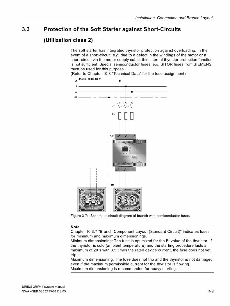
The soft starter has integrated thyristor protection against overloading. In the event of a short-circuit, e.g. due to a defect in the windings of the motor or a short-circuit via the motor supply cable, this internal thyristor protection function is not sufficient. Special semiconductor fuses, e.g. SITOR fuses from SIEMENS, must be used for this purpose.(Refer to Chapter 10.3 "Technical Data" for the fuse assignment)
Figure 3-7: Schematic circuit diagram of branch with semiconductor fuses
Note Chapter 10.3.7 "Branch Component Layout (Standard Circuit)" indicates fuses for minimum and maximum dimensionings. Minimum dimensioning: The fuse is optimized for the I²t value of the thyristor. If the thyristor is cold (ambient temperature) and the starting procedure lasts a maximum of 20 s with 3.5 times the rated device current, the fuse does not yet trip.Maximum dimensioning: The fuse does not trip and the thyristor is not damaged even if the maximum permissible current for the thyristor is flowing. Maximum dimensioning is recommended for heavy starting.
012_
Stan
dard
scha
ltung
und
Sito
r Zei
chnu
ng m
it B
ilder
n.vs
d
U1 V1 W1
V2U2W2
U1 V1 W1
W2 U2 V2
L1
L2
L3
PE
3/N/PE~ 50 Hz 400 V
Q1
G1
M1
F3
Q11
SIRIUS 3RW44 system manualGWA 4NEB 535 2195-01 DS 05 3-9

Installation, Connection and Branch Layout
3.4 Capacitors for Power Factor Improvement
Caution Capacitors must not be connected to the output terminals of the soft starter. If this occurs, the soft starter will be damaged. Active filters, e.g. for reactive power compensation, must not be operated in parallel while the motor control device is in operation.
If capacitors for reactive power compensation are used, they must be connected on the line side of the device. If a contactor disconnector or a main contactor is used in combination with the electronic soft starter, the capacitors must be disconnected from the soft starter when the contactor is open.
3.5 3RW44 in Generator Operation (with 3-Phase Asynchronous Motor)
The 3RW44 soft starters are suitable for generator operation.
Note Depending on the operating speed, connect the generator to the system while in the subsynchronous range (motor operation) and slowly move the machine into the supersynchronous range. Connecting the generator directly in the supersynchronous range may cause soft starter faults.
3.6 Electrical Connection
3.6.1 Control and Auxiliary Current Connection
The SIRIUS 3RW44 soft starter is supplied with two different connection systems:• Screw-type terminals• Spring-loaded terminals
Two control voltage versions are available:• 115 V AC• 230 V AC
SIRIUS 3RW44 system manual3-10 GWA 4NEB 535 2195-01 DS 05

Installation, Connection and Branch Layout
3.6.2 Main Current Connection
All soft starters are equipped with busbar connections for the maincurrent connection.
Size 3RW44 2. An additional box terminal for direct cable connection is supplied as standard with size 3RW44 2. devices.
Sizes 3RW44 3. and 3RW44 4.
For size 3RW44 3. and 3RW44 4. devices, it is possible to retrofit box terminals as optional accessories (refer to Chapter 10.3.9 "Accessories").
Figure 3-8: Connections
Notice The connection of the 3-phase network supply to terminals T1/T2/T3 is not permissible.
1. A1, A2, PE, L+, L-, IN1, IN2, IN3, IN4, T1, T2, 13, 14, 23, 24, 33, 34, 95, 96, 98:Control/auxiliary circuit
2. L1/L2/L3Main circuit infeed
3. T1/T2/T3Main circuit outgoing feeder load
2T1
NONONO
4T2
NC NO
Ue = 200...460V
G/031127123 *E00*
3RW4422-1BC44
6T3
LOCAL INTERFACE
343324231413 95 96 98
SIRIUS5L3
d.c./c.d. 24 V
3L21L1
A1 A2 PE L+ L- IN1 IN2 IN3 IN4 T1 T2
230 V50 - 60 Hz
ESC OK
2.
2.
1.
1.
SIRIUS 3RW44 system manualGWA 4NEB 535 2195-01 DS 05 3-11

Installation, Connection and Branch Layout
3.6.3 Conductor Cross-Sections
A1, A2, PE, L+, L-, IN1, IN2, IN3, IN4, T1, T2, 13, 14, 23, 24, 33, 34, 95, 96, 98
3RW44..-1....3RW44..-6....
3RW44..-2....3RW44..-3....
∅ 5 ... 6 mm / PZ20.8 ... 1.2 Nm7 to 10.3 lb· in —
1 x 0.5 ... 4.0 mm²2 x 0.5 ... 2.5 mm² 2 x 0.25 ... 1.5 mm²
2 x 0.5 ... 1.5 mm²1 x 0.5 ... 2.5 mm² 2 x 0.25 ... 1.5 mm²
— 2 x 0.25 ... 1.5 mm²
AWG 2 x 20 to 14 2 x 24 to 16
10
10
10
L1, L2, L3; T1, T2, T3
3RW44 2.-.... 3RW44 3.-.... 3RW44 4.-.... 3RW44 5.-.... / 3RW44 6.-....
4 ... 6 Nm36 ... 53 lb· in M8x25 10 ... 14 Nm
89 ... 124 lb· in M10x30 14 ... 24 Nm124 ... 210 lb· in M12x40 20 ... 35 Nm
177 ... 310 lb· in
2 x 10 ... 70 mm²2 x AWG 7 ... 1/0
2 x 25 ... 120 mm²2 x AWG 4 ... 250 kcmil
2 x 70 ... 240 mm²2 x AWG 2/0 ... 500 kcmil
2 x 70 ... 240 mm²2 x AWG 2/0 ... 500 kcmil
2 x 10 ... 50 mm²2 x AWG 7 ... 1/0
2 x 16 ... 95 mm²2 x AWG 6 ... 3/0
2 x 50 ...240 mm²2 x AWG 2/0 ... 500 kcmil
2 x 50 ...240 mm²2 x AWG 2/0 ... 500 kcmil
min. 3 x 9 x 0.8max. 10 x 15.5 x 0.8 b≤17 mm b ≤25 mm b≤60 mm
2 x 2.5 ... 16 mm² — — — — — —
2 x 2.5 ... 35 mm²1 x 2.5 ... 50 mm² — — — — — —
2 x 10 ... 50 mm²1 x 10 ... 70 mm²
2 x AWG 10 ... 1/01 x AWG 10 ... 2/0
— — — — — —
4
min 22
b b b
17
17
17
SIRIUS 3RW44 system manual3-12 GWA 4NEB 535 2195-01 DS 05

Display, Controls and Device Interfaces 4Chapter Subject Page
4.1 Display and Controls 4-2
4.2 Device Interfaces 4-3
4.2.1 Local Device Interface 4-3
4.2.2 PROFIBUS Interface (Optional) 4-3
4.3 External Display and Control Unit (Optional) 4-3
SIRIUS 3RW44 system manualGWA 4NEB 535 2195-01 DS 05 4-1

Display, Controls and Device Interfaces
4.1 Display and Controls
Graphic display A graphic display on the front of the device provides information about the functions and status of the soft starter via plain text and symbols when control voltage is applied.
Figure 4-1: Explanation of symbols
Controls There are four keys for operating and adjusting the soft starter:
The current function, depending on the menu item, is shown as text on the display above this key (e.g. select menu, change value or save settings).
The up/down arrow keys are used to navigate through the menu items or to change number values in the settings menu item.
The ESC key is used to quit the current menu item and to jump back to the higher-level menu item.
1 2 3
1. Displays the control unit that has current control priority, i.e. that sends the control commands for the motor.
Display with keys
Serial interface
Control inputs
PLC via PROFIBUS
PC via bus
No control device?
2. Displays the defined user level.
Customer read only
Customer write
3. Displays the current motor status.
No motor
Run up
Motor running
Coasting down
Motor ready to start
OK
ESC
SIRIUS 3RW44 system manual4-2 GWA 4NEB 535 2195-01 DS 05

Display, Controls and Device Interfaces
4.2 Device Interfaces
4.2.1 Local Device Interface
A local device interface on the front side of the starter is provided as standard. This interface can be used to connect either an optional external operating and display module, or the "Soft Starter ES" operating, monitoring and parameterizing software (refer to Chapter 10.3.9 "Accessories", Software) using a PC and connecting cable.
4.2.2 PROFIBUS Interface (Optional)
The SIRIUS 3RW44 soft starter can be equipped with an optional PROFIBUS module (only available for products delivered after 04/06). The soft starter can be connected to PROFIBUS, operated and parameterized via the interface. The "Soft Starter ES" operating, monitoring and parameterizing software (refer to Chapter 10.3.9 "Accessories", Software) can also be connected to this interface using a PC and connecting cable.Simultaneous operation of a 3RW44 with a PROFIBUS interface is not possible in networks where one external conductor is grounded.
4.3 External Display and Control Unit (Optional)
When de-energized, the external display and control unit can be connected to the local device interface via a special connecting cable. After being switched on, the SIRIUS 3RW44 soft starter automatically recognizes that the external display and control unit has been connected. The 3RW44 display will be inverted and the display and control unit's display will be shown normally. The control keys of the 3RW44 will be inactive, meaning that normal handling is only possible via the external display and control unit. → For ordering data, see Chapter 10.3.9.
SIRIUS 3RW44 system manualGWA 4NEB 535 2195-01 DS 05 4-3

Display, Controls and Device Interfaces
SIRIUS 3RW44 system manual4-4 GWA 4NEB 535 2195-01 DS 05

Commissioning 5Chapter Subject Page
5.1 Menu Structure, Navigation, Changing Parameters 5-2
5.1.1 Menu Structure and Navigation 5-2
5.1.2 Changing Parameters: For Example Motor Data 5-3
5.2 Switching on for the First Time 5-4
5.2.1 Recommendation on Procedure for 3RW44 Commissioning 5-4
5.2.2 Quick Start Menu 5-6
5.3 User-specific Commissioning 5-8
5.3.1 Main Menu Item "Settings" 5-9
5.4 Making Settings in the Selected Parameter Set 5-10
5.4.1 Selecting the Parameter Set 5-10
5.4.2 Entering the Motor Data 5-11
5.4.3 Specifying the Starting Mode 5-13
5.4.4 Specifying the Stopping Mode 5-20
5.4.5 Setting Slow Speed Parameters 5-26
5.4.6 Specifying Current Limit Values 5-27
5.4.7 Parameterizing the Inputs 5-28
5.4.8 Parameterizing the Outputs 5-29
5.4.9 Selecting Motor Protection Settings 5-31
5.4.10 Selecting Display Settings 5-33
5.4.11 Specifying the Behavior of the Protective Functions 5-34
5.4.12 Specifying the Names on the Device Display 5-35
5.4.13 Activating the Field Bus Interface (PROFIBUS DP) 5-36
5.4.14 Saving Options 5-37
5.5 Other Device Functions 5-41
5.5.1 Display measured value 5-41
5.5.2 Status Display 5-42
5.5.3 Motor Control (Assigning Control Priority) 5-43
5.5.4 Statistics 5-44
5.5.5 Safety (Specifying the User Level, Parameterization Protection) 5-48
SIRIUS 3RW44 system manualGWA 4NEB 535 2195-01 DS 05 5-1

Commissioning
5.1 Menu Structure, Navigation, Changing Parameters
The 3RW44 functions (parameterization, diagnosis and motor control) can be executed using the four control keys. The menu has various sublevels which must be handled in different ways but are self-explanatory.
5.1.1 Menu Structure and Navigation
Figure 5-1: Menu structure
Display mea-
select
SIEMENS
Menu
3RW44
Main menu level
1
sured value
Settings
select
3
select
4
select
ESC
ESC
ESC
ESC OK
OK
OK
OK
select
1
Status
select
2
display
Settings
select
3
Motor
select
control
Statistics
select
5
ESC OK
ESC OK
ESC OK
select
1Parameter
select
1
set 1
select
Safety
select
6
ESC OK
select
2Parameter
select
set 2
ESC OK
select
3Parameter
select
set 3
ESC OK
4Inputs
select
1Motor 1
select
1
ESC OK
select
2Starting
select
settings
ESC OK
select
3Stopping
select
settings
ESC OK
ESC OK
change
ESC OK
Rated operatingcurrent Ie
1
change
Rated operatingtorque
2
change
Rated operatingspeed
3
29.0 A
100 Nm
1500
1. Sub menu level 2. Sub menu level 3. Sub menu level
SIRIUS 3RW44 system manual5-2 GWA 4NEB 535 2195-01 DS 05

Commissioning
5.1.2 Changing Parameters: For Example Motor Data
Figure 5-2: Changing values, e.g. adjusting motor data
ESC
ESC OK
ESC OK
ESC OK
change
ESC OK
Motor 1 1
Rated operatingcurrent Ie
1
execute
Rated operatingcurrent Ie
execute
Rated operatingcurrent Ie
29.0 A
28.9 A
change
Rated operatingcurrent Ie
1
Display mea-
select
SIEMENS
Menu
3RW44
1
sured value
Settings
select
3
ESC
ESC OK
OK
select
1
Status
select
2
display
Settings
select
3
ESC
ESC OK
select
1Parameter
select
1
set 1
ESC OK
OK
OK
29.0 A
28.9 A
select
SIRIUS 3RW44 system manualGWA 4NEB 535 2195-01 DS 05 5-3

Commissioning
5.2 Switching on for the First Time
Warning Before switching the device on for the first time, verify that the main/control side is wired properly. Make sure that the line and control voltage comply with the device-specific requirements (Chapter 10.3 "Technical Data").
5.2.1 Recommendation on Procedure for 3RW44 Commissioning
Notice This table provides example set values. They are intended informational purposes only and are non-binding. The set values depend on the particular application and must be optimized during commissioning.
Suggested setting
Starting parameters Stopping parameters
Starting mode: Voltage ramp and current limiting (U+current limiting) Stopping mode Parameter
Start voltage %
Starting time s
Current limiting value
Breakaway pulse Stopping time s
Stopping torque %
Application
Conveyor belts 70 10 deactivated deactivated (0 ms) Torque control 10 10
Powered roller conveyors 60 10 deactivated deactivated (0 ms) Torque control 10 10
Compressors 50 10 4 x Ie deactivated (0 ms) Coasting down X X
Small ventilators 30 10 4 x Ie deactivated (0 ms) Coasting down X X
Pumps 30 10 4 x Ie deactivated (0 ms) Pump stop 10 10
Hydraulic pumps 30 10 4 x Ie deactivated (0 ms) Coasting down X X
Stirrers 30 30 4 x Ie deactivated (0 ms) Coasting down X X
Centrifugal machines 30 30 4 x Ie deactivated (0 ms) Coasting down X X
Milling machines 30 30 4 x Ie deactivated (0 ms) Coasting down X X
Large fans 30 60 4 x Ie deactivated (0 ms) Coasting down X X
Mills 50 60 4 x Ie 80 % / 300 ms Coasting down X X
Crushers 50 60 4 x Ie 80 % / 300 ms Coasting down X X
Circular saws/ribbon saws 30 60 4 x Ie deactivated (0 ms) Coasting down X X
SIRIUS 3RW44 system manual5-4 GWA 4NEB 535 2195-01 DS 05

Commissioning
SIRIUS 3RW44 system manual
1. "Soft starter off"2. Reduce starting time in menu item Settings or if current limiting has been set, increase the current limiting value.3. If the torque control is active, check whether the selected limiting torque is high enough(recommended ³ 150 %)
1. "Soft starter off"2. Increase starting time in menu item Settings, or 3. if current limiting has been set, possibly reduce current limiting value
1. "Soft starter off"2. Increase the start voltage or start torque in menu item Settings or 3. if current limiting has been set, possibly increase current limiting value
1. "Soft starter off"2. Decrease the start voltage or start torque in menu item Settings
The motor reaches its nominal rotational speed- quicker than desired with an excessively high starting current- not softly- according to the specified ramp time if no current limiting has been set
The motor reaches its nominal rotational speed- slower than desired, - not at all(motor stuck)
The motor- hums and does not start immediately - does not start at all(motor stuck)
Motor:
The motor starts with a strong sudden increase in torque
Increase stopping time or decrease stopping torque
Soft stop Pump stop
The motor stops abruptly, not softly. The water can be heard during pump operation.
The motor continues to run for too long.
Quick commissioning3RW44 SIRIUS soft starter
Wiring inspection- Control unit and - Power unit
Check and connect the voltages in the control and main circuits
Check set parameters in Settings > Parameter set > Motor.
Set starting and stopping parameters in Settings > Parameter set > Starting or stopping settings according to the table "Suggested setting for commissioning" on the basis of the respective application.
Start command "Soft starter on"
Fault message in display
Does the motor immediately start
softly?
Does the motor reach its nominal rotational
speed quickly and within the desired time?
Switch off soft starter
Which stopping mode is selected?
Motorcomes to a standstill as
desired
Motor:
Yes
No
No
Yes
Yes
No
"Soft starter off"Correct fault (for possible faults see Chapter 7)
Fault message on display?
Initial parameterization or starter in basic factory settings?
Select language
Select application
Set the rated operating current of the motor
Set starting time
Set current limiting value
Save settings
Quick start menu, when switching on for the first time or after executing a command"Basic factory settings"
Information on quick start menu:After applying the control voltage for the first time, you will be automatically directed to the quick start menu. You must complete the entire quick start menu once to commission the soft starter for the first time.If you confirm the last item, "Save settings?", by entering "yes" in the quick start menu, you can only return to this menu by resetting the device back to its basic factory settings. (See manual or operating instructions)This overwrites all settings made up until that point.
Information on application selection:Standard parameters are recommended due to the set type of application. If the required load is not listed, choose a fan in order to preselect the necessary start parameters.In general:The parameters are suggested settings. The parameters may need to be optimized, as explained from Section "Start command 'Soft starter on'" onwards.
"Soft starter off"Correct fault(for possible faults see Chapter 7)
Pump stop, torque control, braking
Save the changed parameters in the menu item: Settings > Saving options > Save settings. Commissioning is complete.
Decrease stopping time
Increase DC braking torque or increase stopping time
Reduce DC braking torque or reduce stopping time
Increase dynamic braking torque
Increase DC braking torque or increase stopping time
DC braking
The motor comes to a standstill but the braking current continues to flow. (Motor hums when at a standstill)
The motor does not come to a standstill
Does the motorcontinue to run during the
braking process at a constant speed (no
recognizablebraking effect)?
Motor does not comes to a standstill, or continues to run at a constant speed during the braking process
Combined braking
The motor comes to a standstill but the braking current continues to flow. (Motor hums when at a standstill)
Reduce DC braking torque or reduce stopping time
Yes
Yes No
YesNo
No
Yes
Coasting down
No
GWA 4NEB 535 2195-01 DS 05 5-5

Commissioning
5.2.2 Quick Start Menu
Important After applying the control supply voltage for the first time, you will automatically be in the quick start menu, which you must go through once to commission the soft starter for the first time.
In the quick start menu, you need to enter the information needed to preset the most important parameters of the soft starter for your application. Starting parameters for typical types of applications are stored in the device parameters. To achieve an optimum motor start, these parameters may need to be optimized on the basis of the connected load using the "Settings" menu item, as described in Chapter 5.4.3 "Specifying the Starting Mode".
If your particular load is not listed, select any load and optimize the defined parameters, if necessary, using the "Settings" menu item as described in Chapter 5.4.3 "Specifying the Starting Mode".
The values of the basic factory settings of the parameters, and the predefined assignment of the control inputs and outputs, are listed in Chapter 10.3 "Technical Data".
Important If you confirm the last item "Save settings - execute?" by entering "Yes" in the quick start menu, you can only return to this menu by resetting the device back to its basic factory settings (refer to "Restoring the factory settings" on Page5-40). This overwrites all settings made up until that point.
SIRIUS 3RW44 system manual5-6 GWA 4NEB 535 2195-01 DS 05

Commissioning
Quick start menu
Figure 5-3: Quick start menu
Language1 English23
DeutschFrançais
select
123
1 Pump23
OK
Yes
1mpe23
Menu
ESC OK
ESC OK
ESC OK
ESC OK
ESC OK
ESC OK
ESC OK
ESC OK
Application
FansCompressors
Pumps
Rated operatingcurrent Ie29.0 A
execute
select
execute
execute
Starting time10 s
Current limiting
Function callSave
Save
execute?
SIEMENS
3RW44
Language1 English23
DeutschFrançais
select
ESC OK
450 %
ESC OK
execute
Starting time
10 s
value
settings
settings
SIRIUS 3RW44 system manualGWA 4NEB 535 2195-01 DS 05 5-7

Commissioning
5.3 User-specific Commissioning
If values are required that differ from the defined parameters in the quick start menu or in the factory settings of the 3RW44, please proceed as follows:
Under the "Settings" menu item, select (refer to Chapter 5.3.1 "Main Menu Item "Settings""):
1. Select parameter set2. Set motor data3. Set starting mode and parameters4. Set stopping mode and parameters5. Set inputs and outputs6. Check motor protection settings7. Save settings
Notice The setting is buffered in a Flash EPROM memory as soon as you change a setting in the menu and execute it using the "OK" button. It is then active in the soft starter from this moment onwards. When the control supply voltage is switched off, this value will be canceled and the previous value restored. In order to permanently save the settings made in the soft starter, you must save the data as described in Chapter 5.3.1 "Main Menu Item "Settings"" and Chapter 5.4.14 "Saving Options".
SIRIUS 3RW44 system manual5-8 GWA 4NEB 535 2195-01 DS 05

Commissioning
5.3.1 Main Menu Item "Settings"
Figure 5-4: Main menu item "Settings"
ESC
ESC OK
ESC OK
ESC OK
ESC OK
ESC OK
ESC OK
ESC OK
Settings3
Parameterset 1
1
Parameterset 2
2
Parameterset 3
3
Inputs 4
Outputs 5
Motor 6
Display 7
Response 8
to ...
Name 9
OK
Display mea-
select
SIEMENS
Menu
3RW44
1
sured value
ESC
ESC OK
OK
select
1
Status
select
2
display
ESC OK
OK
ESC OK
Saving 11
options
ESC OK
ESC OK
Fieldbus 10
ESC OK
select
select
select
select
select
select
select
select
select
select
select
select
protection
settings
SIRIUS 3RW44 system manualGWA 4NEB 535 2195-01 DS 05 5-9

Commissioning
5.4 Making Settings in the Selected Parameter Set
5.4.1 Selecting the Parameter Set
Figure 5-5: Select parameter set
ESC
OK
ESC OK
ESC
ESC OK
Parameter 1
Motor 1 1
Startingsettings
2
Stoppingsettings
3
Slow speed
set 1
Parameter
4
ESC
Current limitvalues
5
ESC
ESC
Settings3
OK
Display mea-
select
SIEMENS
Menu
3RW44
1
sured value
ESC
ESC OK
OK
1
Status
select
2
display
ESC OK
OK
OK
OK
OK
select
select
select
select
select
select
select
SIRIUS 3RW44 system manual5-10 GWA 4NEB 535 2195-01 DS 05
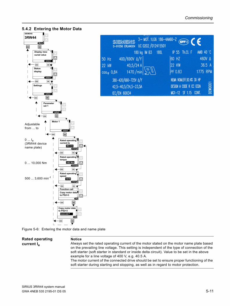
Commissioning
5.4.2 Entering the Motor Data
Figure 5-6: Entering the motor data and name plate
Rated operating current Ie
Notice Always set the rated operating current of the motor stated on the motor name plate based on the prevailing line voltage. This setting is independent of the type of connection of the soft starter (soft starter in standard or inside delta circuit). Value to be set in the above example for a line voltage of 400 V, e.g. 40.5 A.The motor current of the connected drive should be set to ensure proper functioning of the soft starter during starting and stopping, as well as in regard to motor protection.
ESC OK
ESC OK
change
Rated operatingspeed
3
OK
Function call
1470
Copy motor datato PS2+3
ESC OK
OK
Copy motor datato PS2+3
execute?
ESC
ESC OK
change
ESC OK
Motor 1 1
Rated operatingcurrent Ie
1
change
Rated operatingtorque
2
40.5 A
143 Nm
Adjustablefrom ... to
0 ... Ie (3RW44 device name plate)
0 ... 10,000 Nm
500 ... 3,600 min-1
ESC
Parameter 1
set 1
ESC
Settings 3
OK
Display mea-
select
SIEMENS
Menu
3RW44
1
sured value
ESC
ESC OK
OK
select
1
Status
select
2
display
ESC OK
OK
OK
OK
select
select
select
SIRIUS 3RW44 system manualGWA 4NEB 535 2195-01 DS 05 5-11

Commissioning
Rated operating torque
If the rated operating torque of the motor is not indicated on the name plate, it can be calculated using the following formula:
Example
If no value is specified, the value of the basic factory setting is active (0 Nm).When the start command is given and the motor is connected, the required value is automatically calculated once by the soft starter.
Notice If a motor with rated data (current, speed, torque) that differ from the values already entered is connected to the soft starter (e.g. for testing purposes), these rated data must be adapted to the new motor. If 0 Nm is entered as the rated operating torque, the value is automatically calculated once by the soft starter.
M 9.55 P 1000n
-------------××=
9.55 22× kW 10001470 min 1–-----------------------------× 143 Nm=
SIRIUS 3RW44 system manual5-12 GWA 4NEB 535 2195-01 DS 05

Commissioning
5.4.3 Specifying the Starting Mode
Figure 5-7: Specifying the starting mode
change
ESC
ESC OK
ESC OK
ESC OK
select
ESC OK
Starting mode 1
Starting mode
OK
1 Voltage ramp
ESC OK
ESC
Starting 2
OK
settings
Voltage ramp
23
U+curr. limitingTorque control
Starting mode
23
U+curr. limitingTorque control
Voltage ramp1
Starting mode
23
U+curr. limitingTorque control
Voltage ramp1
Starting mode
34
U+curr. limiting
M+curr. limiting
2Torque control
Starting mode
45 Direct on line
3 Torque controlM+curr. limiting
Starting mode
56 Motor heating
4 M+curr. limitingDirect on line
ESC OK
ESC
Motor 1 1
ESC
Parameter 1
set 1
ESC
Settings3
OK
Display mea-
select
SIEMENS
Menu
3RW44
1
sured value
ESC
ESC OK
OK
select
1
Status
select
2
display
ESC OK
OK
OK
OK
OK
OK
select
select
select
select
select
select
select
select
select
SIRIUS 3RW44 system manualGWA 4NEB 535 2195-01 DS 05 5-13

Commissioning
"Voltage ramp" starting mode
Figure 5-8: "Voltage ramp" starting mode
change
ESC
Starting mode 1
ESC
Starting 2
OK
settings
Voltage ramp
OK
ESC
Start voltage 2
40.0 %
OK
ESC
Starting time 5
20 s
OK
ESC
Maximum 6
deactivated
OK
starting time
ESC
Breakaway 8
80 %
OK
voltage
ESC
Breakaway time9
0 ms
OK
4_1_Menü_Startart_Spannungsrampe.wmf
Adjustablefrom ... to
20 ... 100 %
0 ... 360 s
1 ... 1,000 s
40 ... 100 %
0 ... 2,000 ms
ESC
Motor 1 1
ESC
Parameter 1
set 1
ESC
Settings 3
OK
Display mea-
select
SIEMENS
Menu
3RW44
1
sured value
ESC
ESC OK
OK
select
1
Status
select
2
display
ESC OK
OK
OK
OK
OK
select
select
select
select
change
change
change
change
change
Voltage in %
UMotor 100 %
Breakaway voltage
Start voltage
Breakaway timestarting time
Maximum starting time
100 % Voltageat the motor
Time (t) s
SIRIUS 3RW44 system manual5-14 GWA 4NEB 535 2195-01 DS 05

Commissioning
"Voltage ramp with current limiting" starting mode"
Figure 5-9: "Voltage ramp with current limiting" starting mode
4_2_Menü_Startart_Spannungsrampe_mit_Strombegrenzung.wmf
4_1_Menü_Startart_Spannungsrampe.wmf
change
ESC
Starting mode 1
ESC
Starting 2
OK
settings
U+curr. limiting
OK
ESC
Start voltage 2
40.0 %
OK
ESC
Starting time 5
20 s
OK
ESC
Maximum 6
deactivated
OK
starting time
ESC
Curr. limiting 7
450 %
OK
value
ESC
Breakaway 8
80 %
OK
voltage
ESC
Breakaway 9
0 ms
OK
Adjustablefrom ... to
20 ... 100 %
0 ... 360 s
1 ... 1,000 s
125 ... 550 %
40 ... 100 %
0 ... 2,000 ms
ESC
Motor 1 1
ESC
Parameter 1
set 1
ESC
Settings3
OK
Display mea-
select
SIEMENS
Menu
3RW44
1
sured value
ESC
ESC OK
OK
select
1
Status
select
2
display
ESC OK
OK
OK
OK
OK
select
select
select
select
change
change
change
change
change
change
time
Voltage in %
UMotor 100 %
Breakaway voltage
Start voltage
Breakaway timestarting time
Maximum starting time
100 % Voltageat the motor
Time (t) s
Motor current I
I Direct
Beginning deter-mined by specifiedstarting mode, in thiscase breakaway pulse
I Soft starteradjustable currentlimit value
Ie Motor
ne Motor Motor speed n
on-linestartingmotor
Beginning deter-mined by specifiedstarting mode, in thiscase voltage ramp
SIRIUS 3RW44 system manualGWA 4NEB 535 2195-01 DS 05 5-15

Commissioning
"Torque control" starting mode
Figure 5-10:"Torque control" starting mode
change
ESC
Starting mode 1
select
ESC
Starting 2
OK
settings
Torque control
OK
ESC
Start torque 3
50.0 %
OK
ESC
Limiting 4
150 %
OK
ESC
Starting time 5
20 s
OK
ESC
Breakaway 8
80 %
OK
voltage
ESC
Breakaway 9
0 ms
OK
torque
4_3_Drehmomentrampe.wmf
ESC
Maximum 6
deactivated
OK
starting time
Adjustablefrom ... to
10 ... 100 %
20 ... 200 % *
0 ... 360 s
1 ... 1,000 s
40 ... 100 %
0 ... 2,000 ms
ESC
Motor 1 1
ESC
Parameter 1
set 1
ESC
Settings3
OK
Display mea-
select
SIEMENS
Menu
3RW44
1
sured value
ESC
ESC OK
OK
select
1
Status
select
2
display
ESC OK
OK
OK
OK
OK
Limiting torque
*) Notice In order to start the motor, the parameter value should be set to approx. 150 %. It should be high enough to ensure that the motor does not become stuck during run-up. This ensures that enough acceleration torque is generated throughout the entire motor run-up phase.
select
select
select
change
change
change
change
change
change
1
1
Motortorque (M) Nm
Breakaway voltage
Limiting torqueMNom
Start torque
Breakaway time
Starting timeMaximum starting time
MDirect on-line starting(maximum torque to be generated)
Time (t) s
time
SIRIUS 3RW44 system manual5-16 GWA 4NEB 535 2195-01 DS 05

Commissioning
"Torque control with current limiting" starting mode
Figure 5-11: "Torque control with current limiting" starting mode
change
ESC
Starting mode 1
ESC
Starting 2
OK
settings
M+curr. limiting
OK
ESC
Start torque 3
50.0 %
OK
ESC
Starting time 5
20 s
OK
ESC
Maximum 6
deactivated
OK
starting time
ESC
Current 7
450 %
OK
limiting value
ESC
Breakaway 8
80 %
OK
voltage
ESC
Breakaway 9
0 ms
OK
4_4_Drehmomentrampe_mit_Strombegrenzung.wmf
4_3_Drehmomentrampe.wmf
Adjustablefrom ... to
10 ... 100 %
20 ... 200 %
0 ... 360 s
1 ... 1,000 s
125 ... 550 %
40 ... 100 %
0 ... 2,000 ms
ESC
Limiting 4
150 %
OK
torque
ESC
Motor 1 1
ESC
Parameter 1
set 1
ESC
Settings3
OK
Display mea-
select
SIEMENS
Menu
3RW44
1
sured value
ESC
ESC OK
OK
select
1
Status
select
2
display
ESC OK
OK
OK
OK
OK
select
select
select
select
change
change
change
change
change
change
change
1
1
Motortorque (M) Nm
Breakaway voltage
Limiting torqueMNom
Start torque
Breakaway time
Starting timeMaximum starting time
MDirect on-line starting(maximum torque to be generated)
Time (t) s
Motor current I
I Direct
Beginning deter-mined by specifiedstarting mode, in thiscase breakaway pulse
I Soft starteradjustable currentlimit value
Ie Motor
ne Motor Motor speed n
on-linestartingmotor
Beginning deter-mined by specifiedstarting mode, in thiscase torque control
time
SIRIUS 3RW44 system manualGWA 4NEB 535 2195-01 DS 05 5-17

Commissioning
"Direct on line starting" starting mode
Figure 5-12:"Direct on line starting" starting mode
change
ESC
Starting mode 1
ESC
Starting 2
OK
settings
Direct on line
4_5_Menü_Startart_Direktstart_Drehmoment.wmf
001_Stromkurven_ohne_Sanftstarter.wmf
ESC
Motor 1 1
ESC
Parameter 1
set 1
ESC
Settings3
OK
Display mea-
select
SIEMENS
Menu
3RW44
1
sured value
ESC
ESC OK
OK
select
1
Status
select
2
display
ESC OK
OK
OK
OK
OK
OK
select
select
select
select
Motortorque M
MDirect
MNom
nNomMotor speed n
on-linestarting
Motor currentI
IDirect
INom
Motor speedn
nNom
on-linestarting
SIRIUS 3RW44 system manual5-18 GWA 4NEB 535 2195-01 DS 05
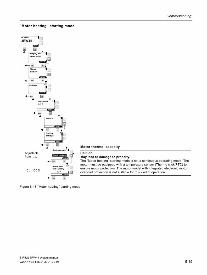
Commissioning
"Motor heating" starting mode
Figure 5-13:"Motor heating" starting mode
change
ESC
Starting mode 1
ESC
Starting 2
OK
settings
Motor heating
OK
ESC
Motor ther- 10
OK
mal capacity20 %
Motor thermal capacity
CautionMay lead to damage to property.The "Motor heating" starting mode is not a continuous operating mode. The motor must be equipped with a temperature sensor (Thermo click/PTC) to ensure motor protection. The motor model with integrated electronic motor overload protection is not suitable for this kind of operation.
ESC
Motor 1 1
ESC
Parameter 1
set 1
ESC
Settings 3
OK
Display mea-
select
SIEMENS
Menu
3RW44
1
sured value
ESC
ESC OK
OK
select
Status
select
2
display
ESC OK
OK
OK
OK
OK
Adjustablefrom ... to
10 ... 100 %
select
select
select
select
change
SIRIUS 3RW44 system manualGWA 4NEB 535 2195-01 DS 05 5-19

Commissioning
5.4.4 Specifying the Stopping Mode
Figure 5-14:Specifying the stopping mode
change
ESC
ESC OK
ESC OK
ESC OK
ESC OK
Stopping 1
Stopping mode
OK
1 Coasting down
ESC OK
ESC
Stopping 3
OK
settings
Coasting down
23
Torque controlPump stop
Stopping mode
23
Torque controlPump stop
Coasting down1
Stopping mode
23
Torque controlPump stop
Coasting down1
Stopping mode
34
Torque control
DC braking
2Pump stop
Stopping mode
45 Comb. braking
3 Pump stopDC braking
4_7_Auslaufart_allgemein.wmf
ESC
Motor 1 1
ESC
Parameter 1
set 1
ESC
Settings 3
OK
Display mea-
select
SIEMENS
Menu
3RW44
1
sured value
ESC
ESC OK
OK
select
Status
select
2
display
ESC OK
OK
OK
ESC
Starting 2
settings
OK
OK
OK
OK
select
select
select
select
select
select
select
select
select
select
1
2
3
1 23
Motorspeed n
ne
Stop commandat soft starter
nCoasting downnTorque-controlled
stopping modenDC braking
Time (t) s
mode
SIRIUS 3RW44 system manual5-20 GWA 4NEB 535 2195-01 DS 05

Commissioning
"Coasting down" stopping mode
Figure 5-15:"Coasting down" stopping mode
change
ESC
Stopping 1
ESC
Stopping 3
settings
Coasting down
OK
ESC
Motor 1 1
ESC
Parameter 1
set 1
ESC
Settings3
OK
Display mea-
select
SIEMENS
Menu
3RW44
1
sured value
ESC
ESC OK
OK
select
Status
select
2
display
ESC OK
OK
OK
ESC
Starting 2
settings
OK
OK
OK
select
select
select
select
select
mode
SIRIUS 3RW44 system manualGWA 4NEB 535 2195-01 DS 05 5-21

Commissioning
"Torque control" stopping mode (soft stop)
Figure 5-16:"Torque control" stopping mode
change
ESC
Stopping 1
ESC
Stopping 3
OK
settings
Torque control
OK
ESC
Stopping time 2
10 s
OK
ESC
Stopping 3
40.0 %
OK
4_8_Menü_Auslaufart_Drehmomentregelung_Pumpenauslauf.wmf
Adjustablefrom ... to
0 ... 360 s
10 ... 100 %
ESC
Motor 1 1
ESC
Parameter 1
set 1
ESC
Settings 3
OK
Display mea-
select
SIEMENS
Menu
3RW44
1
sured value
ESC
ESC OK
OK
select
Status
select
2
display
ESC OK
OK
OK
ESC
Starting 2
settings
OK
OK
OK
select
select
select
select
select
change
change
Motortorque M
MNominal operation
Stopping torque
Stop commandat soft starter
Stopping time Time (t) s
torque
mode
SIRIUS 3RW44 system manual5-22 GWA 4NEB 535 2195-01 DS 05

Commissioning
"Pump stop" stopping mode
Figure 5-17:"Pump stop" stopping mode
change
ESC
Stopping 3
40.0 %
OK
change
ESC
Stopping 1
ESC
Stopping 3
OK
settings
Pump stop
OK
change
ESC
Stopping time 2
10 s
OK
4_8_Menü_Auslaufart_Drehmomentregelung_Pumpenauslauf.wmf
Adjustablefrom ... to
0 ... 360 s
10 ... 100 %
ESC
Motor 1 1
ESC
Parameter 1
set 1
ESC
Settings 3
OK
Display mea-
select
SIEMENS
Menu
3RW44
1
sured value
ESC
ESC OK
OK
select
Status
select
2
display
ESC OK
OK
OK
ESC
Starting 2
settings
OK
OK
OK
select
select
select
select
select
Motortorque M
MNominal operation
Stopping torque
Stop commandat soft starter
Stopping time Time (t) s
mode
torque
SIRIUS 3RW44 system manualGWA 4NEB 535 2195-01 DS 05 5-23

Commissioning
"DC braking" stopping mode
Figure 5-18: "DC braking" stopping mode
Note If the "DC braking" function is selected, the "DC braking contactor" function must be assigned to one output of the soft starter. This output must be used to control an external braking contactor.
change
ESC
Stopping 1
ESC
Stopping 3
OK
settings
DC braking
OK
ESC
Stopping time 2
10 s
OK
ESC
DC braking 5
50 %
OK
Adjustablefrom ... to
0 ... 360 s
20 ... 100 %
ESC
Motor 11
ESC
Parameter 1
set 1
ESC
Settings3
OK
Display mea-
select
SIEMENS
Menu
3RW44
1
sured value
ESC
ESC OK
OK
select
Status
select
2
display
ESC OK
OK
OK
ESC
Starting 2
settings
torque
OK
OK
OK
Motortorque (M)
MNominal
DC braking torque
Motor brakingtorque Stop command
at thesoft starter
Stopping time
Time (t)s
select
select
select
select
select
change
change
Notice The DC braking / combined braking stopping function is not possible in inside delta circuits.
5-24 DC braking stopping mode
mode
SIRIUS 3RW44 system manual5-24 GWA 4NEB 535 2195-01 DS 05
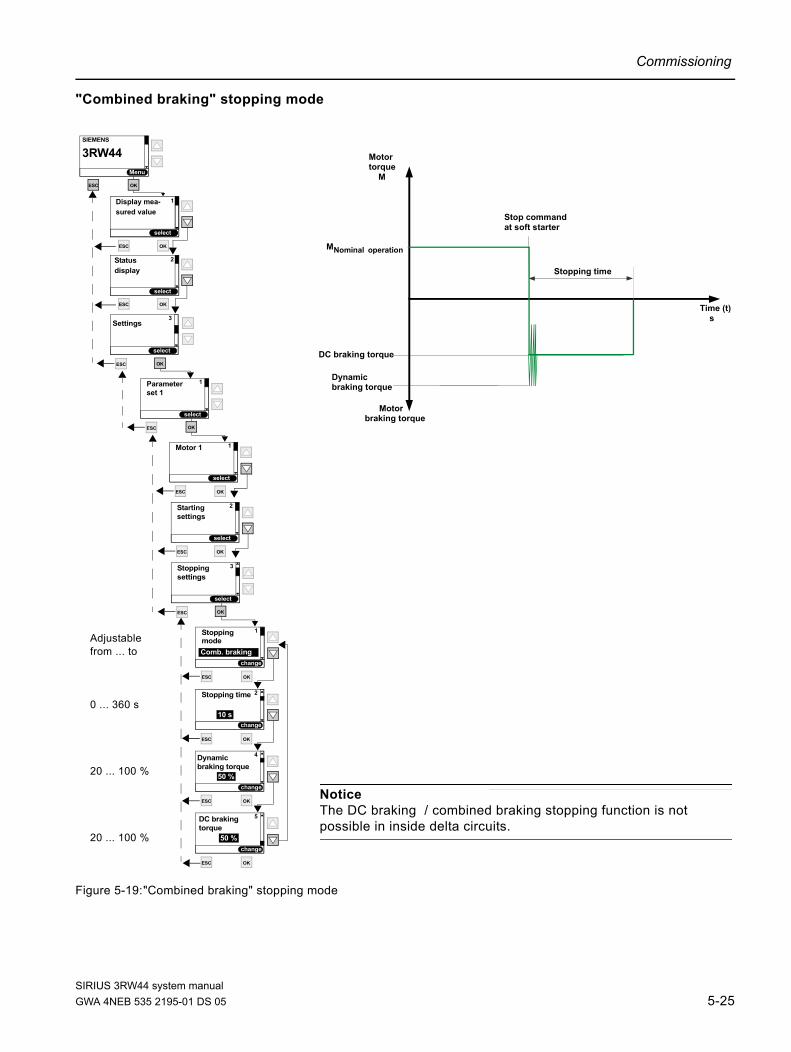
Commissioning
"Combined braking" stopping mode
Figure 5-19:"Combined braking" stopping mode
change
ESC
Stopping 1
ESC
Stopping 3
settings
Comb. braking
OK
ESC
Stopping time 2
10 s
OK
ESC
4
50 %
OK
ESC
DC braking 5
50 %
OK
Dynamic
Adjustablefrom ... to
0 ... 360 s
20 ... 100 %
20 ... 100 %
ESC
Parameter 1
set 1
ESC
Settings3
OK
Display mea-
select
SIEMENS
Menu
3RW44
1
sured value
ESC
ESC OK
OK
select
Status
select
2
display
ESC OK
OK
OK
ESC
Starting 2
settings
braking torque
torque
ESC
Motor 1 1
OK
OK
OK
4_10_Menue_AuslaufartKombiniertes_Bremsen (2).wmf
select
select
select
select
select
change
change
change
Notice The DC braking / combined braking stopping function is not possible in inside delta circuits.
Motortorque M
MNominal operation
Stop commandat soft starter
Stopping time
DC braking torque
Dynamicbraking torque
Motorbraking torque
Time (t) s
mode
SIRIUS 3RW44 system manualGWA 4NEB 535 2195-01 DS 05 5-25
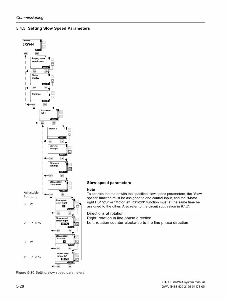
Commissioning
5.4.5 Setting Slow Speed Parameters
Figure 5-20:Setting slow speed parameters
change
ESC
Slow speed 1
ESC
Slow speed 4
OK
parameters
7
OK
ESC
Slow speed 3
7
OK
ESC
Slow speed 2
80.0 %
OK
ESC
Slow speed 4
80.0 %
OK
torque right
factor right
factor left
torque left
Adjustablefrom ... to
3 ... 21
20 ... 100 %
3 ... 21
20 ... 100 %
ESC
Motor 1 1
ESC
Parameter 1
set 1
ESC
Settings3
OK
Display mea-
select
SIEMENS
Menu
3RW44
1
sured value
ESC
ESC OK
OK
select
Status
select
2
display
ESC OK
OK
OK
ESC
Starting 2
settings
ESC
Stopping 3
settings
OK
OK
OK
OKOK
Slow-speed parameters
Note To operate the motor with the specified slow speed parameters, the "Slow speed" function must be assigned to one control input, and the "Motor right PS1/2/3" or "Motor left PS1/2/3" function must at the same time be assigned to the other. Also refer to the circuit suggestion in 9.1.7.
Directions of rotation:Right: rotation in line phase directionLeft: rotation counter-clockwise to the line phase direction
select
select
select
select
select
select
change
change
change
SIRIUS 3RW44 system manual5-26 GWA 4NEB 535 2195-01 DS 05

Commissioning
5.4.6 Specifying Current Limit Values
Figure 5-21:Specifying current limit values
change
ESC
Minimum 1
ESC
Current limit 5
OK
values
OK
ESC
Maximum 2
113 %
OK
current limit
current limit
19.0 %
Adjustablefrom ... to
19 ... 100 %
50 ... 150 %
ESC
Slow speed 4
OK
parameters
ESC
Motor 1 1
ESC
Parameter 1
set 1
ESC
Settings3
OK
Display mea-
select
SIEMENS
Menu
3RW44
1
sured value
ESC
ESC OK
OK
select
Status
select
2
display
ESC OK
OK
OK
ESC
Starting 2
settings
ESC
Stopping 3
OK
settings
OK
OK
OK
OK
OK
select
select
select
select
select
select
select
change
deactivated from version *E09* V1.10.0or 19 to 100 %
deactivated from version *E09* V1.10.0or 50 to 400 %
SIRIUS 3RW44 system manualGWA 4NEB 535 2195-01 DS 05 5-27

Commissioning
5.4.7 Parameterizing the Inputs
Figure 5-22:Parameterizing the inputs
change
ESC
Input 1 - 1
ESC
Inputs 4
OK
ESC
Input 2 - 2
OK
ESC
Input 3 - 3
No action
OK
ESC
Input 4 - 4
Trip Reset
OK
action
action
action
action
Motor right PS1
No action
Parameterization options for control inputs 1 ... 4
No action 1)
Manual operation local 2)
Emergency start 3)
Slow speed 4)
Quick stop 5)
Trip Reset 6)
Motor right parameter set 1 7)
Motor left parameter set 1 8)
Motor right parameter set 2 7)
Motor left parameter set 2 8)
Motor right parameter set 3 7)
Motor left parameter set 3 8)
Notice If the same action is assigned to two different inputs, both of the inputs must also be operated in order to carry out the selected function (e.g. to obtain logical "AND" linking for a start command, assign the "Motor right PS1" function to both input 1 and 2. A start command is only accepted if both inputs are active).
Notice If the soft starter is switched off via a motor protection or inherent device protection tripping, the action cannot be acknowledged using the "Trip reset" function until the displayed cooling time has expired.
Explanation of the possible parameters:1) No action: Input without function.2) Manual operation local: When operated with PROFIBUS, the soft starter control can be transmitted to the inputs by activating the input control. The control function via PROFIBUS is deactivated during this time.3) Emergency start: Error: Current unbalance exceeded, thermal motor model overload, temperature sensor open, temperature sensor short, temperature sensor overload, maximum starting time exceeded, current limit exceeded/undershot, ground fault detected, impermissible le / CLASS setting: In the case of these faults, the motor can be started via the emergency start function despite a pending group error input. An emergency start action will be assigned to one input, and, for example, "Motor right > parameter set 1" assigned to another. The emergency start is active as long as the input is activated. It can also be activated during operation. 4) Slow speed: The motor starts with the values set under the "Slow speed parameters" menu item when the "Slow speed" input and the "Motor right/left parameter set 1/2/3" input are activated at the same time.5) Quickstop: If the input is activated, a normal tripping with the currently set stopping function is carried out (no group error appears). The quickstop is carried out independently of the control priority.6) Trip reset: Pending faults can be acknowledged after rectification.7) Motor right parameter set 1/2/3: The motor starts (with rotation in line phase direction) and stops with the values stored in the respective parameter set.8) Motor left parameter set 1/2/3: This function is active only when the "Slow speed" parameter is active at the same time. The motor starts with the values stored under the "Slow speed parameters" menu item (with rotation counter-clockwise to the line phase direction).
ESC
Settings3
OK
Display mea-
select
SIEMENS
Menu
3RW44
1
sured value
ESC
ESC OK
OK
select
Status
select
2
display
ESC OK
OK
ESC
Parameter 1
OK
ESC
Parameter 2
OK
ESC
Parameter 3
OK
set 1
set 2
set 3
OKOK
Note An input action can only be altered if the respective input is inactive.
select
select
select
select
select
change
change
change
Note The "Trip Reset" input is edge-triggered, the level change from 0 to 24 V DC is analyzed at the input. All other input functions are analyzed on top of the already pending 24 V DC level.
SIRIUS 3RW44 system manual5-28 GWA 4NEB 535 2195-01 DS 05

Commissioning
5.4.8 Parameterizing the Outputs
Figure 5-23:Parameterizing the outputs
change
ESC
Output 1 - 1
ESC
Outputs 5
OK
OK
ESC
Output 2 - 2
OK
ESC
Output 3 - 3
No action
OK
action
action
action
On-time motor
No action
Parameterization options for relay outputs 1 ... 3
No ActionPIO Output 1PIO Output 2Input 1Input 2Input 3Input 4Run upOperation / bypassCoasting downOn-time motorCommand motor-onDC braking contactorGroup warningGroup errorDevice errorsPower onReady to start
ESC
Inputs 4
OK
ESC
Settings3
OK
Display mea-
select
SIEMENS
Menu
3RW44
1
sured value
ESC
ESC OK
OK
select
Status
select
2
display
ESC OK
OK
ESC
Parameter 1
OK
ESC
Parameter 2
OK
ESC
Parameter 3
OK
set 1
set 2
set 3
OK
OKOK
select
select
select
select
select
select
change
change
SIRIUS 3RW44 system manualGWA 4NEB 535 2195-01 DS 05 5-29
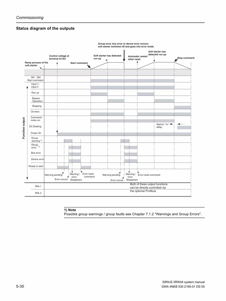
Commissioning
Status diagram of the outputs
1) Note Possible group warnings / group faults see Chapter 7.1.2 "Warnings and Group Errors".
Approx. 1sdelay
IN1 - IN4Start command
Run up
BypassOperation
Stopping
On-time
Power On
Groupwarning
Grouperror
Bus error
Device error
Soft starter has detected run-up
Control voltage atterminal A1/A2
DC Braking
Warning pending Error resetcommand
Error occurs
Warning /error
disappears
PAA 1
PAA 2
Soft starter hasdetected run-up
Warning pending Error-reset command
Error occurs
Warning /error
disappears
Fu
nct
ion
ou
tpu
t
Input 1-input 4
Ramp process of thesoft starter
Automatic restartwhen reset
Group error, bus error or device error occurs;soft starter switches off and goes into error mode
Stop command
Both of these output functionscan be directly controlled viathe optional Profibus.
Commandmotor-on
Ready to start
Start command
1)
1)
ZustandAusgang.wmf
SIRIUS 3RW44 system manual5-30 GWA 4NEB 535 2195-01 DS 05

Commissioning
5.4.9 Selecting Motor Protection Settings
Figure 5-24:Selecting motor protection settings
Notice In the case of heavy starting and set values of tripping class ³CLASS 20, we recommend setting the "Prewarning limit tripping reserve" parameter value to 0 s (deactivated) and increasing the parameter "Prewarning limit motor heat build-up" to 95 %. Otherwise, a warning message regarding motor protection will be issued when starting.
Notice If a CLASS setting other than 5(10a) or 10 is selected, it may be necessary to check and adjust the set values for the rated operating current Ie of the motor (Chapter 5.4.2 "Entering the Motor Data") in all 3 parameter sets, since otherwise the error message "Impermissible Ie/ CLASS settings" may be issued.For the maximum permissible set value for the rated operating current Ie of the motor based on the CLASS settings, please refer to Chapter 10.3.2 "Technical Data Power Unit".
change
ESC
Tripping 1
ESC
Motor 6
CLASS 10
OK
ESC
Current asymmetry 2
40.0 %
OK
ESC
Prewarning limit3
200 s
OK
ESC
Prewarning limit4
80.0 %
OK
ESC
Idle time 5
deactivated
OK
ESC
Pre-charge 6
60 s
OK
tripping reserve
class
limit value
motor heat build-up
time
ESC
Protection against 7
Yes
OK
voltage failure
Adjustablefrom ... to
None; CLASS 5(10a); CLASS 10; CLASS 15; CLASS 20; CLASS 30
30 ... 60 %
0 ... 500 s
0 ... 100 %
deactivated; 1 ... 100 s
deactivated; 60 ... 1,800 s
Yes; No
DeactivatedThermo clickPTC-type A
ESC
Temperature 8
Deactivated
OK
sensor
ESC
Inputs 4
OK
ESC
Settings3
OK
Display mea-
select
SIEMENS
Menu
3RW44
1
sured value
ESC
ESC OK
OK
select
1
Status
select
2
display
ESC OK
OK
ESC
Parameter 1
OK
ESC
Parameter 2
OK
ESC
Parameter 3
OK
set 1
set 2
set 3
OK
ESC
Outputs 5
OKOKOK
OKOK
select
select
select
select
select
select
select
change
change
change
change
change
change
change
protecin
SIRIUS 3RW44 system manualGWA 4NEB 535 2195-01 DS 05 5-31

Commissioning
Notice Use of the 3RW44 to operate motors in hazardous areas: The 3RW44 does not have an ATEX certificate. When an ATEX-certified overload relay is used (e.g. 3RB2 from Siemens), which affects an additional switching element (e.g. contactor 3RT), the 3RW44 can be installed in series to this overload relay, meaning that the ATEX requirements are met.
Important The internal motor overload protection of the SIRIUS 3RW44 soft starter must be deactivated for this kind of installation! (Set value under the menu item "Motor protection/Tripping class": "None" and Motor protection/Temperature sensor: "Deactivated")
M 3~
3RW
3RT
3RB2
Circuit breaker /fuse
SIRIUS 3RW44 system manual5-32 GWA 4NEB 535 2195-01 DS 05

Commissioning
5.4.10Selecting Display Settings
Figure 5-25:Selecting display settings
change
ESC
Language 1
ESC
Display 7
Deutsch
OK
ESC
Contrast 2
50 %
OK
ESC
Lighting 3
OK
ESC
Reaction time 4
60 %
OK
ESC
Auto repeat 5
OK
ESC
Activity moni- 6
30 s
OK
keys
toring time
Possible values
EnglishDeutschFrançaisEspañolItalianoPortuguês
0...100 %
BrightnessResponse to fault Response to warning
0...100 %
Time: 10...250 msSpeed: 10...100 %
deactivated30...1,800 s
ESC
Motor 6
ESC
Inputs 4
OK
ESC
Settings3
OK
Display mea-
select
SIEMENS
3RW44
1
sured value
ESC
ESC OK
OK
select
Status
select
2
display
ESC OK
OK
ESC
Parameter 1
OK
ESC
Parameter 2
OK
ESC
Parameter 3
OK
set 1
set 2
set 3
OK
ESC
Outputs 5
OKOKOK
OKOKOK
OKOK
select
select
select
select
select
select
select
select
change
select
change
select
change
Menu
protection
settings
SIRIUS 3RW44 system manualGWA 4NEB 535 2195-01 DS 05 5-33

Commissioning
5.4.11 Specifying the Behavior of the Protective Functions
Figure 5-26:Specifying the behavior of the protective functions
change
ESC
Overload - therm. 1
ESC
Response 8
Tripping w/o restart
OK
ESC
Overload tem- 2
OK
ESC
Current limit 3
OK
ESC
Overload 4
OK
ESC
Asymmetry 5
20 s
OK
ESC
Ground fault 6
OK
contact block
to ...
motor model
perature sensorTripping w/o restart
value violationWarning
Tripping w/o restart
Warning
Warning
Possible values
Tripping without restartTripping with restartWarning
Tripping without restartTripping with restartWarning
WarningTripping
Tripping without restartTripping with restart
WarningTripping
Warning *Tripping
ESC
Display 7
ESC
Motor 6
ESC
Inputs 4
OK
ESC
Settings3
OK
Display mea-
select
SIEMENS
Menu
3RW44
1
sured value
ESC
ESC OK
OK
select
Status
select
2
display
ESC OK
OK
ESC
Parameter 1
OK
ESC
Parameter 2
OK
ESC
Parameter 3
OK
set 1
set 2
set 3
OK
ESC
Outputs 5
OKOKOK
OKOKOK
OKOKOK
OK
*) Note The ground fault function is only active after completion of run up, not during starting.
select
select
select
select
select
select
select
select
select
change
change
change
change
change
settings
protection
SIRIUS 3RW44 system manual5-34 GWA 4NEB 535 2195-01 DS 05

Commissioning
5.4.12Specifying the Names on the Device Display
Figure 5-27:Specifying the names on the device display
ESC
Name 1
ESC
Name 9
B S01-Z05
OK
ESC
Response 8
to ...
ESC
Display 7ESC
Motor 6
Inputs 4
OK
ESC
Settings3
OK
Display mea-
select
SIEMENS
Menu
3RW44
1
sured value
ESC
ESC OK
OK
select
Status
select
2
display
ESC OK
OK
ESC
Parameter 1
OK
ESC
Parameter 2
OK
ESC
Parameter 3
OK
set 1
set 2
set 3
OK
ESC
Outputs 5
OKOKOK
OKOKOK
OKOKOK
ESC
OKOKOK
OKOK
select
select
select
select
select
select
select
select
select
select
select
protection
settings
SIRIUS 3RW44 system manualGWA 4NEB 535 2195-01 DS 05 5-35

Commissioning
5.4.13 Activating the Field Bus Interface (PROFIBUS DP)
For information on activating the field bus interface, please refer to Chapter 8.4 "Activating the PROFIBUS DP Communication Module (Field Bus Interface) and Setting the Station Address".
Notice If the parameter "Parameters disabled CPU/Master" is set to "Off" (factory setting), the parameters set on the soft starter will be overwritten with the values stored in the GSD file or in the OM when the bus is started. If this is not desired, the parameter must be set to "On".
Fieldbus
select
1
change
interfaceOn
ESC OK
Group diagnosis
select
2
change
Disable
ESC OK
Response to 3
change
Substitute value
ESC OK
CPU master stop
Baud rate 5
12,000 kBd
Station address
select
4
change
126
Status
select
2
display
select
Settings
select
3
select
Display mea-
select
1
sured value
select
SIEMENS
Menu
3RW44
ESC OK
ESC OK
ESC OK
ESC OK
Parameter
select
1
select
set 1
Saving
select
11
select
options
Fieldbus
select
10
select
ESC OK
ESC OK
ESC OK
Substitute value
select
6
select
Parameters disabled
select
7
change
Off
ESC OK
ESC OK
CPU/Master
ESC OK
ESC OK
SIRIUS 3RW44 system manual5-36 GWA 4NEB 535 2195-01 DS 05

Commissioning
5.4.14Saving Options
Specifying the saving options
Figure 5-28:Specifying the saving options
OK
ESC
Function call
ESC
Saving 11
OK
options
Savesettings
OK
ESC
Function call
OK
Restoresettings
OK
ESC
Function call
OK
Restore basicfactory settings
Notice As long as the connected drive is controlled by the soft starter, no parameter changes carried out at the same time can be saved using the "Saving options" menu item. This is only possible after the motor has been shut off by the soft starter.
ESC
Name 9
OK
ESC
Response 8
to ...
ESC
Display 7ESC
Motor 6
Inputs 4
OK
ESC
Settings3
OK
Display mea-
select
SIEMENS
Menu
3RW44
1
sured value
ESC
ESC OK
OK
select
Status
select
2
display
ESC OK
OK
ESC
Parameter 1
OK
ESC
Parameter 2
OK
ESC
Parameter 3
OK
set 1
set 2
set 3
OK
ESC
Outputs 5
OKOKOK
OKOKOK
OKOKOK
ESC
OKOKOK
OKOK
OKOK
ESC OK
Fieldbus 10
select
select
select
select
select
select
select
select
select
select
select
select
protection
settings
SIRIUS 3RW44 system manualGWA 4NEB 535 2195-01 DS 05 5-37

Commissioning
Save settingsSelected settings will be saved.
Figure 5-29:Save settings
OK
ESC
Function call
ESC
Saving 11
options
Savesettings
Yes
ESC
Savesettings
execute?
ESC
Name 9
OK
ESC
Response 8
to ...
ESC
Display 7ESC
Motor 6
Inputs 4
OK
ESC
Settings3
OK
Display mea-
select
SIEMENS
Menu
3RW44
1
sured value
ESC
ESC OK
OK
select
Status
select
2
display
ESC OK
OK
ESC
Parameter 1
OK
ESC
Parameter 2
OK
ESC
Parameter 3
OK
set 1
set 2
set 3
OK
ESC
Outputs 5
OKOKOK
OKOKOK
OKOKOK
ESC
OKOKOK
OKOK
OKOK
OKOK
OKOK
SIEMENS
Menu
3RW44
ESC OK
ESC OK
Fieldbus 10
select
select
select
select
select
select
select
select
select
select
select
select
protection
settings
SIRIUS 3RW44 system manual5-38 GWA 4NEB 535 2195-01 DS 05

Commissioning
Restore settings
Selected settings which have not been saved will be discarded and the previously saved settings will be restored.
Figure 5-30:Restore settings
OK
ESC
Function call
ESC
Saving 11
options
Savesettings
OK
ESC
Function callRestoresettings
Yes
ESC
Restoresettingsexecute?
ESC
Name 9
OK
ESC
Response 8
to ...
ESC
Display 7ESC
Motor 6
Inputs 4
OK
ESC
Settings3
OK
Display mea-
select
SIEMENS
Menu
3RW44
1
sured value
ESC
ESC OK
OK
select
Status
select
2
display
ESC OK
OK
ESC
Parameter 1
OK
ESC
Parameter 2
OK
ESC
Parameter 3
OK
set 1
set 2
set 3
OK
ESC
Outputs 5
OKOKOK
OKOKOK
OKOKOK
ESC
OKOKOK
OKOK
OKOK
OKOK
OKOK
OK
SIEMENS
Menu
3RW44
ESC OK
ESC OK
Fieldbus 10
select
select
select
select
select
select
select
select
select
select
select
select
protection
settings
SIRIUS 3RW44 system manualGWA 4NEB 535 2195-01 DS 05 5-39

Commissioning
Restoring the factory settings
All settings made or saved so far will be discarded and the device will be reset to the basic factory settings (master reset). The quick-start menu must be executed once again.
Figure 5-31:Restoring factory settings
OK
ESC
Function call
ESC
Saving 11
options
Settingssettings
OK
ESC
Function callRestoresettings
Yes
ESC
Restore basicfactory settingsexecute?
OK
ESC
Function callRestore basicfactory settings
Language1 English23
DeutschFrançais
select
ESC OK
ESC
Name 9
OK
ESC
Response 8
to ...
ESC
Display 7ESC
Motor 6
Inputs 4
OK
ESC
Settings3
OK
Display mea-
select
SIEMENS
Menu
3RW44
1
sured value
ESC
ESC OK
OK
select
Status
select
2
display
ESC OK
OK
ESC
Parameter 1
OK
ESC
Parameter 2
OK
ESC
Parameter 3
OK
set 1
set 2
set 3
OK
ESC
Outputs 5
OKOKOK
OKOKOK
OKOKOK
ESC
OKOKOK
OKOK
OKOK
OKOK
OKOK
OK
OK
ESC OK
Fieldbus 10
select
select
select
select
select
select
select
select
select
select
select
select
protection
settings
SIRIUS 3RW44 system manual5-40 GWA 4NEB 535 2195-01 DS 05

Commissioning
5.5 Other Device Functions
5.5.1 Display measured value
Figure 5-32:Display measured value
select
ESC
Phase 1
select
ESC
Display mea- 1
OK
select
ESC
Phase-to- 2
OK
ESC
Blocking 3
OK
ESC
Phase currents 4
OK
Standard
ESC
Power 5
OK
voltages
phase voltages
voltages
0 W
sured value
ESC
Line frequency6
OK
0 Hz
ESC
Supply 7
OK
230 Vvoltage
ESC
Heatsink 8
OK
22 °Ctemperature
ESC
Motor heat 9
OK
0 %build-up
ESC
Remaining time10
OK
65540 sfor tripping
OK
ESC
Function callSwitch offstandard display
Yes
ESC
Switch offstandard display
execute?
Note The "Phase currents" display always shows the currents in the supply cable. This means that, if the soft starter is operated in the "Inside delta circuit" circuit type, the currents measured internally by the soft starter are extrapolated to the supply cable current (phase current) by a factor of 1.73 and displayed. Due to asymmetries, the phase currents displayed in the inside delta circuit may deviate from the currents that are actually running through the supply cables.
ESC OKOK
OKOK
OKOK
OKOK
SIEMENS
Menu
3RW44Note When using the 3RW44 soft starter in an IT system with ground fault monitoring: 3RW44, product version ≤ *E06* and the PROFIBUSDP communication module must not be used in this network configuration. 3RW44 soft starters, from product version *E07* onwards, can be used in combination with the PROFIBUS DP communication module. However, the phase voltage values (UL-N) and phase-to-phase voltage values (UL-L) may be displayed incorrectly on the measured value display of the 3RW44.
select
select
Standard
Standard
Standard
Standard
Standard
SIRIUS 3RW44 system manualGWA 4NEB 535 2195-01 DS 05 5-41

Commissioning
5.5.2 Status Display
Figure 5-33:Status display
ESC
Device status 1
ESC
Status 2
OK
ESC
Active 2
OK
ESC
Type of 3
OK
change
ESC
Direction of 4
OK
ESC
Inputs 5
OK
Standard
ESC
Outputs 6
OK
parameter set
display
ESC
Order number 7
OK
ESC
Firmware 8
OK
information
Parameter set 1
Unknown/fault
Unknown
3RW4435-6BC44
Display mea-
select
SIEMENS
Menu
3RW44
1
sured value
ESC OK
select
ESC OK
OK
Explanation of the messages:
Unknown/fault: No connected motor detected.Star/delta: Soft starter connected in a standard circuit.Inside delta: Soft starter connected in an inside delta circuit.
Unknown: No line phase direction of the main voltage detected at terminals L1-L2-L3.Right: Clockwise line phase direction of the main voltage detected at terminals L1-L2-L3.Left: Counter-clockwise line phase direction of the main voltage detected at terminals L1-L2-L3.
Output 1 - 3: Function corresponds to parameterizationOutput 4: Group errorOutput 5: Internal bypass contactor connectedOutput 6: Device fan activated
select
select
select
select
select
select
select
connection
rotation
SIRIUS 3RW44 system manual5-42 GWA 4NEB 535 2195-01 DS 05
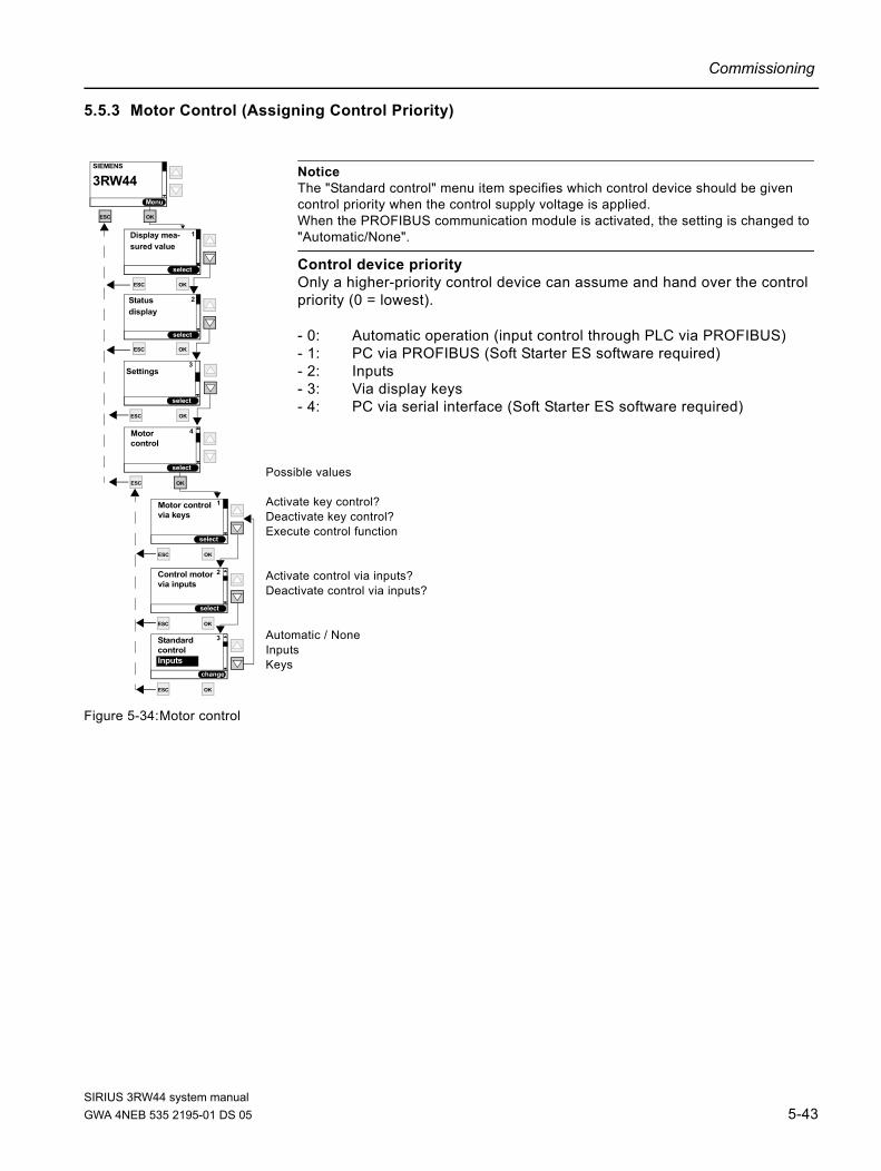
Commissioning
5.5.3 Motor Control (Assigning Control Priority)
Figure 5-34:Motor control
ESC
Motor control 1
ESC
Motor 4
OK
ESC
Control motor 2
OK
change
ESC
Standard 3
OK
via inputs
control
Inputs
via keys
control
Notice The "Standard control" menu item specifies which control device should be given control priority when the control supply voltage is applied. When the PROFIBUS communication module is activated, the setting is changed to "Automatic/None".
Control device priorityOnly a higher-priority control device can assume and hand over the control priority (0 = lowest).
- 0: Automatic operation (input control through PLC via PROFIBUS)- 1: PC via PROFIBUS (Soft Starter ES software required)- 2: Inputs- 3: Via display keys - 4: PC via serial interface (Soft Starter ES software required)
ESC
Settings3
Display mea-
select
SIEMENS
Menu
3RW44
1
sured value
ESC
ESC OK
OK
select
Status
select
2
display
ESC OK
OK
OKPossible values
Activate key control?Deactivate key control?Execute control function
Activate control via inputs?Deactivate control via inputs?
Automatic / NoneInputsKeys
select
select
select
select
SIRIUS 3RW44 system manualGWA 4NEB 535 2195-01 DS 05 5-43

Commissioning
5.5.4 Statistics
Figure 5-35:Statistics
Notice The "Statistics" menu item is available for devices with firmware product version *E04* or higher. The firmware product version is listed on the front of the device below the petrol-colored labeling field. The "Log lists" sub-item can only be used in combination with "Soft Starter ES" parameterizing and diagnostics software. This menu item will be available in the device display from 04/2006.
ESC
Settings3
Display mea-
select
SIEMENS
Menu
3RW44
1sured value
ESC
ESC OK
OK
select
Status
select
2
display
ESC OK
ESC
Motor 4
control
ESC
Log lists 1
ESC
Statistics 5
OK
ESC
Maximum 2
OK
pointer
ESC
Statistics 3
OK
data
OK
OK
OK
select
select
select
select
select
select
SIRIUS 3RW44 system manual5-44 GWA 4NEB 535 2195-01 DS 05

Commissioning
5.5.4.1Log lists
Notice The "Statistics" menu item is available for devices with firmware product version *E04* or higher. The firmware product version is listed on the front of the device below the petrol-colored labeling field. The "Log lists" sub-item can only be used in combination with "Soft Starter ES" parameterizing and diagnostics software. This menu item will be available in the device display from 04/2006.
Notice Log lists cannot be deleted while the motor is running.
ESC
Log lists 1
Statistics 5
ESC
Device errors 1
OK
ESC
Trips 2
OK
ESC
Events 3
OK
All device errorsare recorded and stored
All group errorsare recorded and stored
All warnings and certainactions are recorded and stored
ESC
ESC
Settings3
Display mea-
select
SIEMENS
Menu
3RW44
1
sured value
ESC
ESC OK
OK
select
Status
select
2
display
ESC
ESC
Motor 4
control
OK
OK
OK
OK
OK
select
select
select
select
select
select
select
SIRIUS 3RW44 system manualGWA 4NEB 535 2195-01 DS 05 5-45

Commissioning
5.5.4.2Maximum Pointer
(all minimum and maximum measured values are stored and displayed)
Figure 5-36:Maximum pointer
Notice The "Statistics" menu item is available for devices with firmware product version *E04* or higher. The firmware product version is listed on the front of the device below the petrol-colored labeling field. The "Log lists" sub-item can only be used in combination with "Soft Starter ES" parameterizing and diagnostics software.
ESC
Settings3
Display mea-
select
SIEMENS
Menu
3RW44
1
sured value
ESC
ESC OK
OK
select
Status
select
2
display
ESC OK
ESC
Motor 4
control
ESC
ESC
Currents (%) 1
OK
ESC
Currents (rms) 2
OK
ESC
Phase-to-
OK
Maximum 2
pointer
phase voltages
ESC
Max. tripping
OK
current IA (%)0 %
ESC
Number of
OK
overload trips0
ESC
Minimum line
OK
frequency0 Hz
ESC
Maximum line
OK
frequency0 Hz
ESC
Max. cooling
OK
temperature0 °C
ESC
Max. contact element
OK
heat build-up0 %
Reset allmaximum pointers
OK
Function call3
4
ESC
Max. tripping
OK
current IA (rms)0 %
5
6
7
8
9
10
ESC
Statistics 5
ESC
Reset all
Yes
maximum pointersexecute?
ESC
OK
OK
OK
OK
OK
OK
Standard
ESC
Log lists 1
select
selectselect
select
select
select
select
select
select
Standard
Standard
Standard
Standard
Standard
Standard
SIRIUS 3RW44 system manual5-46 GWA 4NEB 535 2195-01 DS 05

Commissioning
5.5.4.3Statistics Data
Figure 5-37:Statistics data
ESC
No. of starts
OK
motor right0
ESC
No. of starts
OK
motor left0
ESC
Number of
OK
overload trips0 %
ESC OK
No. of stopswith el. brake
0
ESC OK
ESC OK
ESC
No. of starts
OK
Output 3
ESC
No. of starts
OK
Output 4
No. of startsOutput 1
No. of startsOutput 2
Note The operating hours counter is activated as soon as control voltage is applied. Maximum value displayed: 99999:59:59 hours
Note Number of starts motor left, only possible in combination with slow speed.
Note Number of stops with el. brake: The value is increased by one when braking has been chosen as the stopping mode.
Note The value is increase by one when the output is activated.
7
8
9
10
0
11
0
12
0
13
0
14
ESC
Motor current 1
OK
ESC
2
OK
ESC
Last trigger
OK
ESC
Maximum 2
OK
OK
current IA (%)
ESC
Last trigger
OK
current IA (rms)0 A
ESC OK
ESC
Statistics 3
data
Imax (%)0 %
Motor currentImax (rms)
0 A
0 %
Operating hoursdevice
0 : 28 : 02
3
4
5
ESC
Settings3
Display mea-
select
SIEMENS
Menu
3RW44
1
sured value
ESC
ESC OK
OK
select
Status
select
2
display
ESC OK
ESC
Motor 4
control
ESC
Statistics 5
OK
OK
OK
OKOK
Notice The "Statistics" menu item is available for devices with firmware product version *E04* or higher. The firmware product version is listed on the front of the device below the petrol-colored labeling field. The "Log lists" sub-item can only be used in combination with "Soft Starter ES" parameterizing and diagnostics software.
Standard
ESC OK
Operating hoursMotor
0 : 28 : 02
6
OKESC
Log lists 1
select
select
select
select
select
select
Standard
Standard
Standard
Standard
Standard
Standard
Standard
Standard
Standard
Standard
Standard
Standard
Standard
pointer
SIRIUS 3RW44 system manualGWA 4NEB 535 2195-01 DS 05 5-47

Commissioning
5.5.5 Safety (Specifying the User Level, Parameterization Protection)
Figure 5-38:Safety
change
ESC
Enter user 1
ESC
Safety 6
OK
ESC
User level 2
OK
code1000
Customer write
ESC
Safety 6
select
ESC
User level 2
OK
Customer
ESC
Settings3
Display mea-
select
SIEMENS
Menu
3RW44
1
sured value
ESC
ESC OK
OK
select
Status
select
2
display
ESC OK
ESC
Motor 4
control
ESC
Statistics 5
ESC
Settings3
Display mea-
select
SIEMENS
Menu
3RW44
1
sured value
ESC
ESC OK
OK
select
Status
select
2
display
ESC OK
ESC
Motor 4
control
ESC
Statistics 5
OK
OK
OKOK
OK
OK
OK
OK
change
ESC
Enter user 1
code1000
OK
execute
ESC
Enter user 1
OK
code1000
execute
ESC
Enter user 1
code1001
OK
select
select
select
select
select
select
select
select
read only
SIRIUS 3RW44 system manual5-48 GWA 4NEB 535 2195-01 DS 05

Device Functions 6Chapter Subject Page
6.1 Various Parameter Sets 6-2
6.2 Starting Modes 6-3
6.2.1 Voltage Ramp 6-3
6.2.2 Torque Control 6-5
6.2.3 Breakaway Pulse in Combination with the Voltage Ramp or Torque Control Starting Mode
6-7
6.2.4 Current Limiting in Combination with the Voltage Ramp or Torque Control Starting Mode
6-9
6.2.5 Starting Mode: Direct On Line 6-10
6.2.6 Starting Mode: Motor Heating 6-10
6.3 Stopping Modes 6-11
6.3.1 Coasting Down 6-11
6.3.2 Torque Control and Pump Stop 6-12
6.3.3 DC Braking / Combined Braking 6-13
6.4 Slow Speed Function 6-16
6.5 Current Limit Values for Load Monitoring 6-18
6.6 Motor Protection Functions 6-19
6.7 Inherent Protection 6-23
SIRIUS 3RW44 system manualGWA 4NEB 535 2195-01 DS 05 6-1

Device Functions
6.1 Various Parameter Sets
The soft starter provides three individually adjustable parameter sets. One starting mode and stopping mode can be directly specified per parameter set.
Applications • Starting Dahlander motors (variable-speed drive).• Starting an application with different load conditions (e.g. empty or full
conveyor belt).• Separate starting of up to three drives with different run-up behavior
(e.g. compressor and pump).
SIRIUS 3RW44 system manual6-2 GWA 4NEB 535 2195-01 DS 05

Device Functions
6.2 Starting Modes
Different starting functions can be selected thanks to the large number of applications for which the SIRIUS 3RW44 soft starter can be used. The motor start can be set optimally according to application and deployment.
6.2.1 Voltage Ramp
The simplest type of soft start with the SIRIUS 3RW44 is achieved using a voltage ramp. The terminal voltage of the motor is increased from a parameterizable start voltage to line voltage within an adjustable starting time. This starting mode is preset in the quick start menu.
Start voltage The level of the start voltage determines the switch-on torque of the motor. A smaller start voltage results in a smaller start torque and smaller starting current. The start voltage should be high enough so that the motor starts immediately and softly when the start command is sent to the soft starter.
Starting time The length of the starting time determines the time in which the motor voltage is increased from the set start voltage to the line voltage. This influences the acceleration torque of the motor, which drives the load during the run-up procedure. A longer starting time results in a smaller acceleration torque over the motor run-up. This results in a longer and softer motor run-up. The length of the starting time should be selected in such a way that the motor reaches its nominal speed within this time. If this time is too short, i.e. if the starting time ends before the motor has run up, an extremely high starting current will occur at that moment, reaching the value of the direct starting current at this speed. The soft starter can, in this case, switch itself off via the internal overload protection function and go into fault mode.
Maximum starting time
The "Maximum starting time" parameter can be used to determine the time after which the drive must have completed its run-up. If the drive is not in nominal operation upon completion of the set time, the starting procedure is aborted and an error message is generated.
Internal run-up recognition
The soft starter features an internal run-up recognition. If a completed motor run-up is recognized by the device, the internal bypass contacts close and the thyristors are bridged. If this run-up recognition is performed before the set run-up time is completed, the ramp is aborted and the motor voltage is immediately increased to 100 % of the line voltage before the internal bypass contacts are closed.
SIRIUS 3RW44 system manualGWA 4NEB 535 2195-01 DS 05 6-3

Device Functions
Figure 6-1: Function principle of voltage ramp
Figure 6-2: Function principle of voltage ramp / torque curve
Typical applications for voltage rampsThe voltage ramp function principle is suitable for all types of application.If test runs with the application are carried out using motors that are smaller than those to be used in the actual system, we recommend using the "Voltage ramp" starting mode.For machines requiring a breakaway pulse (inverse load response, e.g. in mills or crushers), the breakaway pulse must be set as described in Chapter 6.2.3 "Breakaway Pulse in Combination with the Voltage Ramp or Torque Control Starting Mode". The "Voltage ramp+current limiting (U+current limiting)" starting mode is recommended for heavy starting.
Voltage in %
Time (t)s
UMotor100 %
100 %Voltage atthe motor
Parameterizablestart voltage
Parameterizablestarting time
Longer starting time
1 Short starting time
2
1
2
5_01
_Fun
ktio
nspr
inzi
p Sp
annu
ngsr
ampe
.wm
f
Motortorque (M)
Nm
Speed (n)min-1
MDirect on-line starting(maximum torquethat can be generated)
MNom
Motor has run up and isin nominal operation (nNom).The runup is detected and thebypass contacts close.
3
Parameterizablestart voltage
MSoft startLonger ramp time
MLoad (e. g. Fan)
1
Parameterizabletorque starting time
1Accelerationtorque2
Short ramp timeMSoft start
2
3
5_02
_Fun
ktio
nspr
inzi
p Sp
annu
ngsr
ampe
_Dre
hmom
entv
erla
uf.w
mf
SIRIUS 3RW44 system manual6-4 GWA 4NEB 535 2195-01 DS 05

Device Functions
6.2.2 Torque Control
The motor speed and torque are calculated using the voltage and current r.m.s. values, as well as the associated phase information between the line voltage and the motor current (= cos ϕ = sensorless control), and the motor voltage is controlled accordingly. Torque control means that the torque generated in the motor is linearly increased from a parameterizable start torque up to a parameterizable end torque within an adjustable starting time. The advantage over the voltage ramp is the improved mechanical run-up behavior of the machine.The soft starter controls the torque generated at the motor continuously and linearly according to the set parameters until the motor has completely run up.For optimum torque control during the starting procedure, the motor data of the motor connected to the soft starter should be entered in the selected parameter set using the menu item "Setting".
Start torque The height of the start torque determines the switch-on torque of the motor. A smaller start torque results in a smaller run-up torque and smaller starting current. The start torque should be high enough so that the motor starts immediately and softly when the start command is sent to the soft starter.
Limiting torque The level of the limiting torque determines which maximum torque should be generated in the motor during run-up. This value can thus also act as an adjustable torque limitation.In order to achieve a successful run-up, the parameter value should be set to approx. 150 %. It should, however, be at least high enough so that the motor does not get stuck during run-up. This ensures that enough acceleration torque is generated throughout the entire motor run-up phase.
Starting time The length of the starting time determines the time in which the start torque is increased to the end torque.A longer starting time results in a smaller acceleration torque over the motor run-up. This results in a longer and softer motor run-up. The length of the starting time should be selected in such a way that the motor accelerates softly until it reaches its nominal speed.If the starting time ends before the motor has completely run up, the torque is limited to the set limiting torque until the soft starter recognizes the run-up process and closes the internal bypass contacts.
Maximum starting time
The "Maximum starting time" parameter can be used to determine the time after which the drive must have completed its run-up. If the drive is not in nominal operation upon completion of the set time, the starting procedure is aborted and an error message is generated.
Internal run-up recognition
The soft starter features an internal run-up recognition. If a completed motor run-up is recognized within the set starting time, the ramp will be aborted and the motor voltage will immediately be increased to 100 % of the line voltage. The internal bypass contacts close and the thyristors are bridged.
SIRIUS 3RW44 system manualGWA 4NEB 535 2195-01 DS 05 6-5

Device Functions
Note The torque generated in the motor and controlled by the soft starter can at no time be higher than the value of a similar direct on line start at the same speed.
Figure 6-3: Function principle of torque control
Typical applications for torque controlTorque control is suitable for all applications, especially in cases where a consistent and smooth start is required. For machines requiring a breakaway pulse (inverse load response, e.g. in mills or crushers), the breakaway pulse must be set as described in Chapter 6.2.3 "Breakaway Pulse in Combination with the Voltage Ramp or Torque Control Starting Mode". The "Torque control+current limiting (M+current limiting)" starting mode is recommended for heavy starting (refer to Chapter 6.2.4 "Current Limiting in Combination with the Voltage Ramp or Torque Control Starting Mode").
Parameterizablelimiting torque
Parameterizableramp time
Motortorque (M)Nm
Motor has run up and isin nominal operation (n ).The runup is detected and the bypass contacts close.
Nom
NNom
Parameterizablestart voltage
Accelerationtorque
5_03
_Fun
ktio
nspr
inzi
p D
rehm
omen
trege
lung
.wm
f
SIRIUS 3RW44 system manual6-6 GWA 4NEB 535 2195-01 DS 05

Device Functions
6.2.3 Breakaway Pulse in Combination with the Voltage Ramp or Torque Control Starting Mode
This function is required for load machines with inverse torque behavior. Typical applications are mills, crushers or drives with plain bearings. In such cases, it may be necessary to create a breakaway pulse at the beginning of the machine's start process. The breakaway pulse is set via the breakaway voltage and the breakaway time. Using the breakaway pulse, the high limiting friction of the load can be overcome and the machine can be set into motion.The breakaway pulse can be used in combination with the voltage ramp, torque control or current limiting starting modes, and is superimposed on these during the set breakaway time.
Breakaway voltage The breakaway voltage setting determines height of the the breakaway torque to be generated. Its maximum value can be 100 % of the start torque generated in direct on line starting. The pulse should be at least high enough for the motor to start immediately when the soft starter receives the start command.
Breakaway time The breakaway time specifies how long the breakaway voltage should be applied. Upon completion of the breakaway time, the soft starter finishes its run-up process with the selected starting mode, e.g. voltage ramp or torque control. The selected breakaway time should be at least long enough so that, after the set time has elapsed, the motor does not remain stationary again but rather directly continues to accelerate in the selected starting mode.If 0 ms is set as the breakaway time (default), the breakaway pulse function is deactivated.
Figure 6-4: Function principle of breakaway pulse / torque control
Time (t)s
MNom
MLoad (e. g. Crusher)
1
1
M
2
3
3
2
MSoft start
Motortorque (M)
Nm
Direct on-line starting(maximum torque that can begenerated)
Breakaway pulse combined withtorque regulation orvoltage ramp
Parameterizablebreakaway voltage
Parameterizablestart torque/start voltage
Parameterizablebreakaway voltage
Parameterizablestarting time
Accelerationtorque
Motor has run up and isin nominal operation (nNom).The runup is detected and thebypass contactsclose.
5_04
_Fun
ktio
nspr
inzi
p Lo
sbre
chim
puls
Dre
hmom
entre
gelu
ng .w
mf
SIRIUS 3RW44 system manualGWA 4NEB 535 2195-01 DS 05 6-7

Device Functions
Typical applications for breakaway pulses
Typical applications for breakaway pulses are load machines with inverse torque behavior, e.g. crushers and mills.
Note A breakaway pulse that is set too high may lead to the error message "Current measurement range exceeded". Remedy: Use larger starter dimensions or a lower breakaway voltage. Only set the breakaway pulse when it is really required (e.g. for mills and crushers). A wrongly set breakaway pulse, e.g. for pumps, may lead to the error message "Incorrect start conditions".
SIRIUS 3RW44 system manual6-8 GWA 4NEB 535 2195-01 DS 05

Device Functions
6.2.4 Current Limiting in Combination with the Voltage Ramp or Torque Control Starting Mode
The starter continuously measures the phase current (motor current) using the integrated current transformer.During motor run-up, it is possible to set a current limiting value on the soft starter.The current limiting can be activated if "Voltage ramp+current limiting" or "Torque control+current limiting" has been selected as the starting mode and a value has been entered in the relevant parameter.During the starting procedure, the phase current is limited to the set value until it falls below this value. A set breakaway pulse is superimposed on the current limiting during the breakaway time.
Current limiting value As a factor of the motor rated current, the current limiting value is set to the maximum current required during the starting procedure. If the set current limiting value is reached, the motor voltage is lowered (or regulated) by the soft starter in such a way that the current will not exceed the set current limiting value. The set current limiting value must be at least selected high enough for enough torque to be created in the motor to bring the drive into rated operation. A typical value can be 3 to 4 times the value of the rated operating current (Ie) of the motor.
Run-up recognition The soft starter features an internal run-up recognition. If a completed motor run-up is recognized, the motor voltage is immediately increased to 100 % of the line voltage. The internal bypass contacts close and the thyristors are bridged.
Figure 6-5: Current limiting with soft starter
Typical applications for current limitingUsed in applications with a large centrifugal mass (mass reactance) and hence long starting times, e.g. large fans, in order to lighten the load on the supply network.
Motor current
nn
Beginning determinedby specified startingmode, in this case voltage ramp
Beginning determinedby specified startingmode, in this casebreakaway pulse
5_05
_Stro
mbe
gren
zung
mit
Sanf
tsta
rter.w
mf
SIRIUS 3RW44 system manualGWA 4NEB 535 2195-01 DS 05 6-9

Device Functions
6.2.5 Starting Mode: Direct On Line
If the "Direct on line" starting mode is set, the motor voltage is immediately increased to line voltage when it receives the start command. This resembles the starting behavior with a contactor, i.e. the starting current and start torque are not limited.
NoteDue to the high starting current of the motor, the error "Current limit exceeded" may occur in "Direct on line" starting mode. It may be necessary for the soft starter to be dimensioned larger.
Run-up recognition The soft starter features an internal run-up recognition. If a completed motor run-up is recognized, the internal bypass contacts close and the thyristors are bridged.
6.2.6 Starting Mode: Motor Heating
If IP54 motors are used outdoors, condensation occurs in the motor during cooler periods (e.g. overnight or in the winter). This may lead to leakage currents or short-circuits when the devices are switched on.A pulsating DC current is fed into the motor winding to warm it up. If the "Motor heating" starting mode is selected, a heating capacity can be entered in the settings. This capacity should be chosen in such a way that the motor will not be damaged. The setting range for the heating capacity extends from 10 - 100 %. This corresponds to a motor current of approximately 5 - 30 % of the motor rated current.
Typical applications for motor heatingUsed for example in outdoor drives to minimize condensation inside the motor.
CautionMay lead to damage to property. The motor heating starting mode is not a continuous operating mode. The motor must be equipped with a temperature sensor (Thermo click/PTC) to ensure motor protection. The motor model with integrated electronic motor overload protection is not suitable for this kind of operation.
SIRIUS 3RW44 system manual6-10 GWA 4NEB 535 2195-01 DS 05

Device Functions
6.3 Stopping Modes
Different stopping functions can be selected thanks to the large numbers of applications for which the SIRIUS 3RW44 soft starter can be used. The motor stop can be set optimally according to application and deployment. If a start command is output during the stopping procedure, this procedure is aborted and the motor is started up again using the specified starting mode.
NoteIf guided stopping is selected as stopping mode (soft stop, pump stop or braking), it may be necessary to select a larger dimensioned branch (soft starter, wiring, branch protection elements and the motor), since the current exceeds the rated motor current during the stopping procedure.
Figure 6-6: Stopping modes in general
6.3.1 Coasting Down
Coasting down means that when the on command to the soft starter is removed, the energy feed to the motor via the soft starter is interrupted. The motor will coast down freely, only driven by the mass reactance (centrifugal mass) of the rotor and the load. This is also referred to as a natural run-down. A larger centrifugal mass means a longer coasting-down.
Typical applications for coasting downCoasting down is used for loads with no special requirements in terms of stopping behavior, e.g. large fans.
4_7_
Ausl
aufa
rten_
allg
emei
n.w
mf
1
2
3
1 23
Motorspeed n
ne
Stop commandat soft starter
nCoasting downnTorque-controlled
stopping modenDC braking
Time (t) s
SIRIUS 3RW44 system manualGWA 4NEB 535 2195-01 DS 05 6-11

Device Functions
6.3.2 Torque Control and Pump Stop
In "Torque-controlled stopping" and "Pump stop" mode, the coasting down / natural run-down procedure of the load is extended. This function is set if abrupt stopping of the load is to be prevented. This is typical in applications with small mass reactances or high counter torques.For optimum torque control during the stopping procedure, the motor data of the motor connected to the soft starter should be entered in the selected parameter set using the menu item "Setting".
Stopping time and stopping torque
The "Stopping time" parameter of the soft starter can be used to specify for how long power should be fed into the motor after removal of the on command. Within this stopping time, the torque generated in the motor is continuously and linearly reduced to the set stopping torque and the application is smoothly stopped.
Pump stop In pump applications, so-called water hammers can occur if the drive is stopped abruptly without using pump stop. These water hammers are caused by the sudden stall and the accompanying pressure deviations in the pump. They cause noise and a mechanical impact on the piping system, as well as on the flaps and valves it contains.
Figure 6-7: Soft stop / pump stop
Typical applications for soft stop / pump stopUse soft stop / pump stop• in pumps to prevent water hammers.• in conveyor belts to prevent materials from toppling.
CautionRisk of damage to property. For optimum motor protection, use a combination of electronic motor overload protection and evaluation of a temperature sensor integrated into the motor.
4_8_
Men
ü_A
usla
ufar
t_D
rehm
omen
trege
lung
_P
umpe
naus
lauf
.wm
f
Motortorque M
MNominal operation
Stopping torque
Stop commandat soft starter
Stopping time Time (t) s
SIRIUS 3RW44 system manual6-12 GWA 4NEB 535 2195-01 DS 05

Device Functions
6.3.3 DC Braking / Combined Braking
In DC braking or combined braking, the coasting down / natural run-down of the load is shortened.The soft starter imposes a (pulsating) DC current in phases L1 and L3 on the motor stator. This current creates a permanent magnetic field in the stator. Since the rotor is still rotating due to its mass reactance, currents are induced into the short-circuited rotor winding, creating a braking torque.
Notice The DC braking / combined braking stopping function is not possible in inside delta circuits.
Note The pulsating DC current loads the network asymmetrically and the motor and the branch must be dimensioned accordingly for the higher current load during the stopping procedure. It may be necessary to overdimension the soft starter.
Note Two braking versions are available: Combined braking: Use the combined braking function if applications with small mass reactances (centrifugal masses) are to be stopped (Jload ≤Jmotor). The real stopping time can vary during braking processes when the combined braking function is applied. Use the function DC braking if a braking time of uniform length is to be achieved.DC braking: Use the DC braking function if applications with larger mass reactances (centrifugal masses) are to be stopped (Jload ≤ 5 x Jmotor).An external brake contactor is required for the DC braking function!
CautionRisk of damage to property. A combination of electronic motor overload protection and evaluation of a temperature sensor integrated into the motor is recommended for optimum motor protection.
Stopping mode: combined brakingIf combined braking is selected, the dynamic braking torque, DC braking torque and stopping time parameters can be set on the starter.
Dynamic braking torque
The dynamic braking torque determines the extent of the braking effect at the start of the braking process in order to reduce the speed of the motor. The braking process is then continued using the DC braking function.
DC braking torque The height of the DC braking torque determines the brake force of the motor.If the motor accelerates again during DC braking, the dynamic braking torque must be increased.
SIRIUS 3RW44 system manualGWA 4NEB 535 2195-01 DS 05 6-13

Device Functions
Stopping time The stopping time determines how long the braking torque should be applied to the motor. The braking time should be long enough to bring the load to a complete standstill.To achieve a sufficient braking effect until standstill, the centrifugal mass (J) of the load should not exceed that of the motor. The stopping time should be long enough for the motor to come to a standstill. The soft starter has no standstill recognition; if required, this must be accomplished using external measures.
Note The real stopping time can vary during braking processes when the combined braking function is applied.
Figure 6-8: Combined braking
Stopping mode: DC brakingIf the DC braking function is selected, the stopping time and DC braking torque parameters can be set on the starter. With this braking type, one output of the soft starter must be switched over to DC braking to control an external braking contactor. Please refer to Chapter 9 for circuit suggestions.The optimum parameters must be adjusted on the machine under appropriate load conditions.
DC braking torque The height of the DC braking torque determines the brake force of the motor.
4_10
_Men
ue_A
usla
ufar
tKom
bini
erte
s_Br
emse
n (2
).wm
f
Motortorque M
MNominal operation
Stop commandat soft starter
Stopping time
DC braking torque
Dynamicbraking torque
Motorbraking torque
Time (t) s
SIRIUS 3RW44 system manual6-14 GWA 4NEB 535 2195-01 DS 05

Device Functions
Stopping time The stopping time determines how long the braking torque should be applied to the motor. The braking time should be long enough to bring the load to a complete standstill.
To achieve a sufficient braking effect until standstill, the load's mass moment of inertia should not be higher than 5 times the motor's mass moment of inertia. (Jload≤ 5 x Jmotor).
The soft starter has no standstill recognition; if required, this must be accomplished using external measures.
Figure 6-9: DC braking
Typical applications for DC brakingUse "DC braking" in lathes (e.g. for tool changeover) and circular saws.
Motortorque (M)
MNominal
DC braking torque
Motor brakingtorque Stop command
at soft starter
Stopping time
Times
operation
SIRIUS 3RW44 system manualGWA 4NEB 535 2195-01 DS 05 6-15

Device Functions
6.4 Slow Speed Function
This function allows an asynchronous motor to be temporarily operated in both directions at a speed that is lower than the rated operating speed. The rated operating speed nmotor of the motor is determined by its line frequency (f) and its number of pole pairs (p).
A resulting slow speed frequency for the motor is defined by a specific thyristor control. However, it is necessary for this function that only a reduced torque can be generated in the motor. Due to the possibility of increased heating of the motor, this function is not suitable for continuous operation.
The slow speed factor and the slow speed torque can be entered individually for both directions of rotation.
Slow speed factor By adjusting the slow speed factor, it is possible to control the motor with a speed (nSlow speed) that is lower than the rated operating speed either in or against the line phase direction.
Slow speed torque The torque generated in the motor can be influenced using the slow speed torque. The maximum torque which can be created depends on the slow speed torque that is set. 100 % slow torque can correspond to approx. 30 % of the motor rated operating torque.
Figure 6-10:Slow speed function
Typical applications for slow speed functionThis function is suitable for applications with a low counter torque, e.g. when machine tools are positioned.
Note In addition to the set parameters, the motor-specific properties and the connected load also affect the speed resulting from the slow speed function and the slow speed torque generated in the motor.
nMotor f 60p------×=
nSlow speednNom
Slow speed factor-----------------------------------------------=
Line frequency
Resulting "slow speed frequency"
SIRIUS 3RW44 system manual6-16 GWA 4NEB 535 2195-01 DS 05

Device Functions
Note To control the motor with the specified slow speed parameters, "Slow speed" must be assigned to one control input, and "Motor right PS1/2/3" or "Motor left PS1/2/3" must be assigned to the other. Also refer to the circuit suggestion in Chapter 9.1.7. Directions of rotation: Right: rotation in line phase directionLeft: rotation counter-clockwise to the line phase direction
Notice Due to the reduced motor speed and the accompanying reduced self-cooling of the motor, this operating mode is not recommended for continuous operation.
CautionRisk of damage to property. For optimum motor protection, use a combination of electronic motor overload protection and evaluation of a temperature sensor integrated into the motor.
SIRIUS 3RW44 system manualGWA 4NEB 535 2195-01 DS 05 6-17

Device Functions
6.5 Current Limit Values for Load Monitoring
It is possible to set minimum and maximum current limit values; if these are exceeded or undershot, a message can be output.
Minimum current limit value
The minimum current limit value can, for example, be used to indicate a V-belt break and the corresponding no-load current of the motor, or when the fan filter is clogged.
Maximum current limit value
The maximum current limit value can be used to determine increased power loss in the application, e.g. caused by storage damage.
SIRIUS 3RW44 system manual6-18 GWA 4NEB 535 2195-01 DS 05

Device Functions
6.6 Motor Protection Functions
The motor overload protection is based on the motor winding temperature. This temperature is used to determine whether the motor is overloaded or is operating within its normal rating.
The winding temperature can either be calculated using the integratedelectronic motor overload function, or be measured using a connected motor thermistor.
Both versions must be combined (=activated) in order to obtain so-called full motor protection. This combination is recommended for optimum motor protection.
Motor overload protection
The current flow is measured during motor operation using current measurement via converters in the soft starter. The temperature rise of the winding is calculated on the basis of the configured rated operating current of the motor.Depending on the set tripping class (CLASS setting) and protection parameters, a warning or a trip is generated when the characteristic curve is reached.
SIRIUS 3RW44 system manualGWA 4NEB 535 2195-01 DS 05 6-19

Device Functions
Tripping class (electronic overload protection)
The tripping class (CLASS) indicates the maximum tripping time in which a protective device must trip at a value 7.2 times that of the rated operating current in cold condition (motor protection acc. to IEC 60947). The tripping characteristics indicate the tripping time in relation to the tripping current (refer to Chapter 10.4 "Tripping Characteristics").Different CLASS characteristics are available for normal or heavy starting.
Note The rated data of the soft starters are based on normal starting (CLASS 10). For heavy starting (> CLASS 10), it may be necessary to overdimension the soft starter.
Current asymmetry limit value
Three-phase asynchronous motors respond to slight line voltage asymmetries with a higher asymmetrical current consumption. This increases the temperature in the stator and rotor winding.
The asymmetric limit value is a percent value by which the motor current may deviate in the individual phases.
The reference value for the evaluation is the maximum deviation from the average value of the three phases.
Asymmetry is defined as a deviation of more than 40 % from the average value.
Prewarning limit tripping reserve
If the set prewarning time limit is reached, which is based on the calculated time until the motor is stopped by the motor protection function, a message can be output.
Prewarning limitmotor heat build-up
A message can be generated if the set thermal prewarning limit of the motor is reached. Tripping of the motor protection occurs at 100 %.
Idle time The idle time is a specified time for the cooling behavior of the motor model after a normal shutdown, i.e. not after overload trips.
After this period, the "Thermal motor model" of the motor starter is set to 50 % if the motor heat build-up is still at > 50 %, otherwise it is set to 0 %.
This enables frequent start procedures (inching). Depending on the CLASS settings, these lead to tripping where motor protection according to IEC 60947 is used.
SIRIUS 3RW44 system manual6-20 GWA 4NEB 535 2195-01 DS 05

Device Functions
The following graphic illustrates the cooling behavior with and without idle time:
Figure 6-11: Idle time
The idle time can be set between 1 and 100 s.
CautionRisk of damage to property. If the idle time is changed (0 = deactivated), motor protection according to IEC 60947 (CLASS 10A, 10, 15, 20, 30) is no longer ensured. This means that there will be no system protection in such cases. We recommend that parallel protection measures be taken.
CautionRisk of damage to property. The motor must be designed for such inching operation, otherwise the overload may cause permanent damage.
Pre-charge time When the thermal motor model is tripped, a pre-charge time is started to let the motor cool down; the motor is prevented from being restarted before the pre-charge time has elapsed.
Protection against voltage failure
If protection against voltage failure is active and the control supply voltage breaks down while a trip is pending, the current trip condition of the thermal motor model and the current pre-charge time are stored in the soft starter. When the control supply voltage returns, the trip condition of the thermal motor model before voltage failure will be restored.
WithoutTripping limit
On
t
t
t
υ
υ
Overload trip
Motor
Off
No
Tripping limit
Motortemp. rise
Idle time Idle time
Overload trip
Idle time
WithIdle time
SIRIUS 3RW44 system manualGWA 4NEB 535 2195-01 DS 05 6-21
Device Functions
Temperature sensor The temperature sensor motor protection function measures the motor's stator winding temperature directly using a measuring sensor in the motor, i.e. a motor with a measuring sensor wound into the stator winding is required.Two different types of measuring sensors are available for the evaluation.• PTC type A thermistors ("Type A sensors")• Thermo click
The wiring and the sensors are checked for wire breaks and short-circuits.
Notice If the soft starter is switched off via a motor protection or device protection tripping, the action cannot be acknowledged using the "Trip reset" function until the displayed cooling time has expired.
SIRIUS 3RW44 system manual6-22 GWA 4NEB 535 2195-01 DS 05

Device Functions
6.7 Inherent Protection
The soft starter has integrated device protection to prevent the thyristors from becoming thermally overloaded. This is achieved via current measurement using converters in the three phases and, additionally, by measuring the temperature with thermosensors at the thyristor heatsink.If a fixed warning threshold is exceeded, a message is generated by the soft starter. If the fixed tripping value is exceeded, the soft starter switches off automatically.
After a trip has occurred, a fixed 30-second pre-charge time must be observed before the starter can be restarted.
If protection against voltage failure is active and the control supply voltage breaks down while a trip is pending, the current trip condition of the thermal motor model and the current pre-charge time are stored in the soft starter. When the control supply voltage returns, the trip condition of the thermal inherent protection before voltage failure will be restored.
In order to protect the thyristors from being destroyed by short-circuits (e. g. in the event of cable damage or a shorted coil in the motor), SITOR semiconductor fuses must be connected upstream. The corresponding selection tables can be found in Chapter 10.3.7 "Branch Component Layout (Standard Circuit)" and in Chapter 10.3.8 "Branch Component Layout (Inside Delta Circuit)".
Notice If the soft starter is switched off via a motor protection or device protection tripping, the action cannot be acknowledged using the "Trip reset" function until the displayed cooling time has expired.
SIRIUS 3RW44 system manualGWA 4NEB 535 2195-01 DS 05 6-23

Device Functions
SIRIUS 3RW44 system manual6-24 GWA 4NEB 535 2195-01 DS 05

Diagnosis and Messages 7Chapter Subject Page
7.1 Diagnosis, Messages 7-2
7.1.1 Status Messages 7-2
7.1.2 Warnings and Group Errors 7-2
7.1.3 Device Errors 7-7
SIRIUS 3RW44 system manualGWA 4NEB 535 2195-01 DS 05 7-1
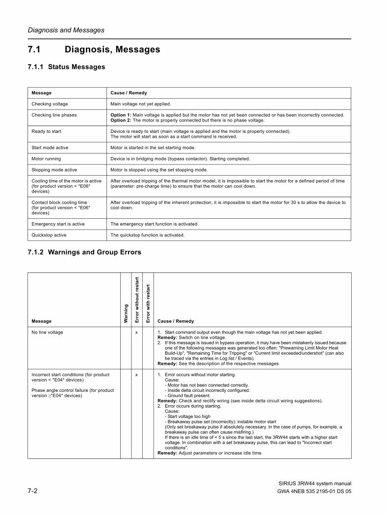
Diagnosis and Messages
7.1 Diagnosis, Messages
7.1.1 Status Messages
7.1.2 Warnings and Group Errors
Message Cause / Remedy
Checking voltage Main voltage not yet applied.
Checking line phases Option 1: Main voltage is applied but the motor has not yet been connected or has been incorrectly connected.Option 2: The motor is properly connected but there is no phase voltage.
Ready to start Device is ready to start (main voltage is applied and the motor is properly connected).The motor will start as soon as a start command is received.
Start mode active Motor is started in the set starting mode.
Motor running Device is in bridging mode (bypass contactor). Starting completed.
Stopping mode active Motor is stopped using the set stopping mode.
Cooling time of the motor is active (for product version < *E06* devices)
After overload tripping of the thermal motor model, it is impossible to start the motor for a defined period of time (parameter: pre-charge time) to ensure that the motor can cool down.
Contact block cooling time(for product version < *E06* devices)
After overload tripping of the inherent protection, it is impossible to start the motor for 30 s to allow the device to cool down.
Emergency start is active The emergency start function is activated.
Quickstop active The quickstop function is activated.
Message War
ning
Erro
r w
ithou
t res
tart
Erro
r w
ith r
esta
rt
Cause / Remedy
No line voltage x 1. Start command output even though the main voltage has not yet been applied. Remedy: Switch on line voltage.2. If this message is issued in bypass operation, it may have been mistakenly issued because
one of the following messages was generated too often: "Prewarning Limit Motor Heat Build-Up", "Remaining Time for Tripping" or "Current limit exceeded/undershot" (can also be traced via the entries in Log list / Events).
Remedy: See the description of the respective messages
Incorrect start conditions (for product version < *E04* devices)
Phase angle control failure (for product version ≥*E04* devices)
x 1. Error occurs without motor starting. Cause: - Motor has not been connected correctly. - Inside delta circuit incorrectly configured. - Ground fault present.
Remedy: Check and rectify wiring (see inside delta circuit wiring suggestions).2. Error occurs during starting.
Cause: - Start voltage too high - Breakaway pulse set (incorrectly): instable motor start(Only set breakaway pulse if absolutely necessary. In the case of pumps, for example, a breakaway pulse can often cause misfiring.) If there is an idle time of < 5 s since the last start, the 3RW44 starts with a higher start voltage. In combination with a set breakaway pulse, this can lead to "Incorrect start conditions".
Remedy: Adjust parameters or increase idle time.
SIRIUS 3RW44 system manual7-2 GWA 4NEB 535 2195-01 DS 05

Diagnosis and Messages
Loss of phase L1 x Option 1:Phase L1 missing, drops or fails while motor is running.A trip occurs due to a voltage drop in the permissible rated operational voltage of >15 % >100 ms during starting, or >200 ms in bypass operation.Remedy: Connect L1 or rectify voltage drop.
Option 2: The connected motor is too small and the error message is issued immediately after switching to bridging mode.Remedy: Set rated operating current for connected motor correctly or set to minimum (if motor current is lower than 10 % of the set Ie, the motor cannot be operated with this starter).
Option 3: Starter used in IT system with ground fault monitoring:3RW44, product version ≤ *E06* and the PROFIBUS DP communication module must not be used in this network configuration.Remedy: Replace starter with 3RW44, product version ≥ *E07*. This version can be used in combination with the PROFIBUS DP communication module. However, the phase voltage values (UL-N) and phase-to-phase voltage values (UL-L) may be displayed incorrectly on the measured value display of the 3RW44.
Loss of phase L2 x Option 1: Phase L2 missing, drops or fails while motor is running.A trip occurs due to a voltage drop in the permissible rated operational voltage of >15 % >100 ms during starting, or >200 ms in bypass operation.Remedy: Connect L2 or rectify voltage drop.
Option 2: The connected motor is too small and the error message is issued immediately after switching to bridging mode.Remedy: Set rated operating current for connected motor correctly or set to minimum (if motor current is lower than 10 % of the configured Ie, the motor cannot be operated with this starter).
Option 3: Starter used in IT system with ground fault monitoring:3RW44, product version ≤ *E06* and the PROFIBUS DP communication module must not be used in this network configuration.Remedy: Replace starter with 3RW44, product version ≥ *E07*. This version can be used in combination with the PROFIBUS DP communication module. However, the phase voltage values (UL-N) and phase-to-phase voltage values (UL-L) may be displayed incorrectly on the measured value display of the 3RW44.
Loss of phase L3 x Option 1: Phase L3 missing, drops or fails while motor is running. A trip occurs due to a voltage drop in the permissible rated operational voltage of >15 % >100 ms during starting, or >200 ms in bypass operation.Remedy: Connect L3 or rectify voltage drop.
Option 2: The motor that is connected is too small and the error message is issued immediately after switching to bridging mode.Remedy: Set rated operating current for connected motor correctly or set to minimum (if motor current is lower than 10 % of the configured Ie, the motor cannot be operated with this starter).
Option 3: Starter used in IT system with ground fault monitoring:3RW44, product version ≤ *E06* and the PROFIBUS DP communication module must not be used in this network configuration.Remedy: Replace starter with 3RW44, product version ≥ *E07*. This version can be used in combination with the PROFIBUS DP communication module. However, the phase voltage values (UL-N) and phase-to-phase voltage values (UL-L) may be displayed incorrectly on the measured value display of the 3RW44.
Missing load phase T1 x Motor phase T1 is not connected.Remedy: Connect motor correctly.
Missing load phase T2 x Motor phase T2 is not connected.Remedy: Connect motor correctly.
Missing load phase T3 x Motor phase T3 is not connected.Remedy: Connect motor correctly.
Message War
ning
Erro
r w
ithou
t res
tart
Erro
r w
ith r
esta
rt
Cause / Remedy
SIRIUS 3RW44 system manualGWA 4NEB 535 2195-01 DS 05 7-3

Diagnosis and Messages
Supply voltage below 75 % x Control supply voltage is below 75 % of the required nominal voltage for longer than 100 ms (voltage failure, voltage drop, wrong control supply voltage).Remedy: Check control supply voltage.
Supply voltage below 85 % x Control supply voltage is below 85 % of the required nominal voltage for longer than 2 s (voltage failure, voltage drop).Remedy: Check control supply voltage.
Supply voltage above 110 % x Control supply voltage is above 110 % of the required nominal voltage for longer than 2 s (voltage peaks, wrong control supply voltage).Remedy: Check control supply voltage.
Current unbalance exceeded x x Phase currents are asymmetric (asymmetric load). Message is output when the asymmetry is greater than the set limit (parameter: Current asymmetry limit value).Remedy: Check load or change parameter value.
Thermal motor model overload x x x The thermal motor model has tripped. After an overload trip, restarting is blocked until the pre-charge time has elapsed.
Remedy in the case of unwanted tripping:- Check whether the motor rated operating current Ie is incorrectly set or- Change CLASS setting or- Reduce switching frequency, or- Deactivate motor protection (CLASS OFF)
Prewarning limit motor heat build-up x Motor heat build-up is greater than the parameter value for: Prewarning limit motor heat build-up. The thermal motor model approaches an overload trip, depending on the set value. For heavy starting and set values of tripping class ≥CLASS 20, we recommend increasing the "Prewarning Limit Motor Heat Build-Up" parameter value to 95 %.
Remaining time for tripping undershot x Time until overload tripping of the thermal motor model is shorter than the set value for the "Prewarning limit remaining time for tripping" parameter.For heavy starting and set values of tripping class ≥ CLASS 20, we recommend increasing the "Prewarning limit tripping reserve" parameter value to 0 s (deactivated).
Line overvoltage (for product version < *E04* devices)
Line voltage too high (for product version ≥*E04* devices)
x Applied 3-phase line voltage is not suitable for the device or longer voltage peaks occur.Tripping occurs due to the permitted rated voltage being exceeded by >10 % >500 ms. From product version *E02* upwards, the internal tripping limit has been increased to >18 % >2000 ms. Remedy: Apply correct voltage.
Current range exceeded x 1. A very high current has occurred (beyond the measuring range of the current transformers integrated in the soft starter). This may happen in the case of: direct on line starting, breakaway pulses or combined braking.
Remedy: If the "Voltage ramp"” starting mode is selected, extend the set ramp time or lower the breakaway voltage or braking torque. The soft starter may be dimensioned too small for the motor.2. If this message is issued during start-up, it may have been mistakenly issued because one
of the following messages was generated too often: "Prewarning limit motor heat build-up", "Remaining time for tripping" or "Current limit exceeded/undershot" (can also be traced via the entries in Log list / Events).
Remedy: Refer to the description of the respective messages.
Motor stalled - switched off(for product version < *E07* devices only)
x A very high current suddenly occurs in bridging mode, e.g. when the motor stalls (I > 4 x IeMotor higher than 100 ms).Remedy: Check motor.
Overcurrent(for product version < *E07* devices only)
x A current of more than 6 times the rated operating current has occurred for a long period of time.Remedy: Activate current limiting or check dimensioning (device/motor).
Power unit overheated x x Overload trip of the thermal model for the power unit.Remedy: Wait until the device has cooled down, perhaps set a lower current limit or reduce the switching frequency (too many starts in succession).Check whether the motor is blocked or the ambient temperature is too high in the vicinity of the soft starter (for derating above 40 °C, refer to Chapter 10.3 "Technical Data").
Message War
ning
Erro
r w
ithou
t res
tart
Erro
r w
ith r
esta
rt
Cause / Remedy
SIRIUS 3RW44 system manual7-4 GWA 4NEB 535 2195-01 DS 05

Diagnosis and Messages
Power unit overtemperature x The temperature of the thermal model for the power unit is higher than the permissible temperature for continuous operation. Remedy: Check the motor operating current or check if the ambient temperature is too high in the vicinity of the soft starter (for derating above 40 °C, refer to Chapter 10.3 "Technical Data").
Temperature sensor short-circuit x x x Temperature sensor is short-circuited at terminals T1 / T2.Remedy: Check temperature sensor.
Temperature sensor open x x x Temperature sensor faulty at terminals T1 / T2, one line is not connected or no sensor is connected at all.Remedy: Check temperature sensor or, if none is connected: deactivate temperature sensor.
Temperature sensor overload x x x Temperature sensor has tripped at terminals T1 / T2, motor overheated.Remedy: Wait until the motor has cooled down and, if necessary, check motor.
Max. starting time exceeded x The set maximum starting time is shorter than the actual run-up time of the motor. Remedy: Extend "Max. starting time" parameter, increase current limiting value or check load connected to the motor for mechanical faults.
Current limit exceeded / undershot x x Set current limit has been exceeded or undershot, e.g. due to a clogged fan filter or by the motor stalling.Remedy: Check the motor / load for the reason for the current limit value violation, or adjust the limit value according to the existing load conditions.
Ground fault detected x x One phase is connected to ground (only possible in bypass operation).Remedy: Check connections and wiring.
Manual operation local connection break
x Connection to the PC has been interrupted (if PC-controlled) or (if motor is key-controlled) no key has been pressed for a long period of time (see Settings > Display > Activity monitoring time in Chapter 5.4.10).Control will be handed over to the inputs if these have requested control priority.Remedy: Reconnect the PC or increase activity monitoring time and press a key at regular intervals.
Impermissible Ie / CLASS settings x The set rated operating current Ie of the motor (Chapter 5.4.2 "Entering the Motor Data") exceeds in at least one of the three parameter sets the corresponding, maximum permissible set current, based on the selected CLASS settings (Chapter 5.4.9 "Selecting Motor Protection Settings"). In product version ≥ *E07* devices, the corresponding parameter set (PS) in which the incorrect value is to be found will be displayed For maximum permissible adjustable values, please refer to Chapter 10.3 "Technical Data". If the soft starter is connected in an inside delta circuit, the motor feeder may have been incorrectly wired (Chapter 9.1.5 "3RW44 in an Inside Delta Circuit"), so that the "Status display / Type of connection" menu item (Chapter 5.5.2 "Status Display") shows "Unknown / fault".Remedy: Check the set rated operating current of the motor in all 3 parameter sets, reduce the CLASS setting or overdimension the soft starter. In the case of inside delta circuits, check the wiring of the motor feeder to ensure that it corresponds to the specified circuit diagrams.If the motor is not activated, this is only a status message. However, the message becomes an error without restart once a start command is issued.
No external start parameters received (for product version ≥ *E06* devices)
x Only when operated with PROFIBUS DP. Incorrect or non-permissible parameter values have been sent by the PLC.Remedy: The incorrect parameter can be read out and corrected to a permissible value via the Soft Starter ES software.
PIO error (for product version ≥ *E06* devices)
x PIO error (process image of the outputs faulty) is displayed:• If Motor right and Motor left have been simultaneously selected (Cause 1) or• parameter set 4 has been selected via the PLC (Cause 2).Remedy: • Automatic deletion once Motor right and Motor left are deactivated again (for Cause 1),
or• a valid parameter set (PS 1-3) is set (for Cause 2).
Message War
ning
Erro
r w
ithou
t res
tart
Erro
r w
ith r
esta
rt
Cause / Remedy
SIRIUS 3RW44 system manualGWA 4NEB 535 2195-01 DS 05 7-5
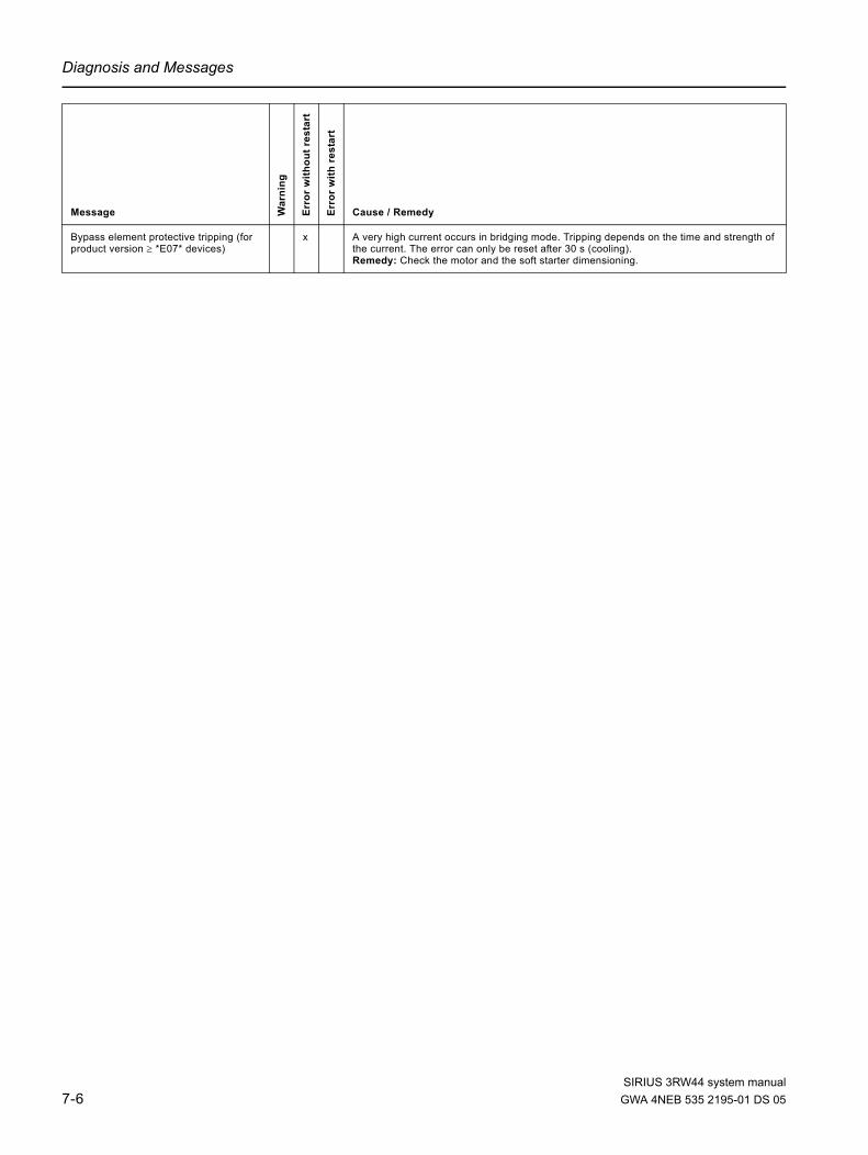
Diagnosis and Messages
Bypass element protective tripping (for product version ≥ *E07* devices)
x A very high current occurs in bridging mode. Tripping depends on the time and strength of the current. The error can only be reset after 30 s (cooling).Remedy: Check the motor and the soft starter dimensioning.
Message War
ning
Erro
r w
ithou
t res
tart
Erro
r w
ith r
esta
rt
Cause / Remedy
SIRIUS 3RW44 system manual7-6 GWA 4NEB 535 2195-01 DS 05

Diagnosis and Messages
7.1.3 Device Errors
Note Some error messages may be incorrect (e.g. Loss of phase L1, although L2 is missing).
Note When using the 3RW44 soft starter in an IT system with ground fault monitoring: 3RW44, product version ≤ *E06* and the PROFIBUS DP communication module must not be used in this network configuration. 3RW44 soft starters from product version *E07* onwards can be used in combination with the PROFIBUS DP communication module. However, phase voltage values (UL-N) and phase-to-phase voltage values (UL-L) may be displayed incorrectly on the measured value display of the 3RW44.
1) Possible ohmic value for a defective thyristor: <2 kOhm (L-T).
Message Cause / Remedy
Contact element damaged (for product version ≥*E04* devices)
At least one bypass element is welded and/or at least one thyristor has shorted. This message is generated when the control supply voltage is applied and the current flow is being measured (via the soft starter), but no start command has been issued. 1)
Remedy: Contact your SIEMENS contact partner or Technical Assistance (see Chapter “Important Notes”)
Switching element 1 failed Thyristor in phase L1 has shorted. (This message is displayed when the start command is issued.) 1)
Remedy: Contact your SIEMENS contact partner or Technical Assistance.
Switching element 2 failed Thyristor in phase L2 has shorted. (This message is displayed when the start command is issued.) 1)
Remedy: Contact your SIEMENS contact partner or Technical Assistance.
Switching element 3 failed Thyristor in phase L3 has shorted. (This message is displayed when the start command is issued.) 1)
Remedy: Contact your SIEMENS contact partner or Technical Assistance.
Flash memory error The device memory is faulty.Remedy: Contact your SIEMENS contact partner or Technical Assistance.
Device not identified Device has not yet been identified. It must be given identification data. Remedy: Contact your SIEMENS contact partner or Technical Assistance.
Versions not matching The version does not match the firmware. Remedy: Contact your SIEMENS contact partner or Technical Assistance.
Bypass element fault The bypass contactor is welded or defective.Remedy: Contact your SIEMENS contact partner or Technical Assistance.
Heatsink thermistor open Option 1: The temperature sensor on the heatsink of the starter is not connected or is defective. Option 2: 3RW4465 or 3RW4466 may have a defective fan on the front of the starter.Remedy: For 3RW4465 and 3RW4466 only: Try to rectify the fault after a cooling time of approx. 30 to 60 minutes by switching the control supply voltage off and then on again. If successful, check whether the fan on the front of the soft starter runs when a start command is issued. If not, it may be necessary to replace the fan. (The fan on the front of the starter and the fan on the bottom of the device must both be running in fault-free operation).For all 3RW44 starters: If switching the control supply voltage off and on again does not cause the error message to reset, contact your SIEMENS contact partner or Technical Assistance.
Heatsink thermistor short The temperature sensor on the heatsink of the starter is defective.Remedy: Contact your SIEMENS contact partner or Technical Assistance.
SIRIUS 3RW44 system manualGWA 4NEB 535 2195-01 DS 05 7-7

Diagnosis and Messages
SIRIUS 3RW44 system manual7-8 GWA 4NEB 535 2195-01 DS 05

PROFIBUS DP Communication Module 8Chapter Subject Page
8.1 Introduction 8-4
8.1.1 Definitions 8-5
8.2 Data Transmission 8-6
8.2.1 Data Transmission Options 8-6
8.2.2 Communication Principle 8-6
8.3 Installation of the PROFIBUS DP Communication Module 8-7
8.3.1 Insertion of the PROFIBUS DP Communication Module (Field Bus Interface)
8-7
8.4 Activating the PROFIBUS DP Communication Module (Field Bus Interface) and Setting the Station Address
8-9
8.4.1 Introduction 8-9
8.4.2 Activating the PROFIBUS DP Communication Module via the Display, Setting the Station Address and Saving the Settings
8-10
8.4.3 Activating the PROFIBUS DP Communication Module (Field Bus Interface) and Setting the Station Address via the Device Interface using the "Soft Starter ES Premium" or the "Soft Starter ES + SP1" Software
8-13
8.5 Soft Starter Configuration 8-15
8.5.1 Introduction 8-15
8.5.2 Configuration with the GSD File 8-15
8.5.3 Configuration with the Soft Starter ES Premium Software 8-16
8.5.4 Diagnostics Package 8-16
8.5.5 Soft Starter ES Parameterizing Software 8-16
8.6 PROFIBUS DP Commissioning using the GSD File in STEP 7 (Example)
8-17
8.6.1 Introduction 8-17
8.6.2 Configuration using the Device Master Data (GSD) in STEP 7 8-19
SIRIUS 3RW44 system manualGWA 4NEB 535 2195-01 DS 05 8-1

PROFIBUS DP Communication Module
8.6.3 Integration into the User Program 8-21
8.6.4 Switching On 8-21
8.6.5 Flow Diagram PROFIBUS DP - Starting the Soft Starter 8-22
8.7 Process Data and Process Images 8-23
8.8 Diagnosis via LED Display 8-25
8.9 Diagnosis with STEP 7 8-26
8.9.1 Reading the Diagnosis 8-26
8.9.2 Options for Reading the Diagnosis 8-26
8.9.3 Structure of the Slave Diagnosis 8-27
8.9.4 Station Status 1 to 3 8-28
8.9.5 Master PROFIBUS Address 8-30
8.9.6 Manufacturer Code 8-30
8.9.7 Code-Based Diagnosis 8-31
8.9.8 Module Status 8-32
8.9.9 Channel-Based Diagnosis 8-33
8.10 Data Formats and Data Sets 8-35
8.10.1 Characteristics 8-35
8.11 Identification Number (ID No.), Error Codes 8-38
8.11.1 Identification Number (ID No.) 8-38
8.11.2 Error Codes for Negative Data Set Acknowledgement 8-38
8.12 Data Sets 8-40
8.12.1 Data Set 68 - Reading/Writing the Process Image of the Outputs 8-41
8.12.2 Data Set 69 - Reading the Process Image of the Inputs 8-42
8.12.3 Data Set 72 - Log List - Reading Device Errors 8-43
8.12.4 Data Set 73 Log List - Reading the Trippings 8-44
8.12.5 Data Set 75 Log List - Reading Events 8-44
8.12.6 Data Set 81 - Reading the Basic Settings of Data Set 131 8-48
8.12.7 Data Set 82 - Reading the Basic Settings of Data Set 132 8-48
8.12.8 Data Set 83 - Reading the Basic Settings of Data Set 133 8-48
8.12.9 Data Set 92 - Reading the Device Diagnosis 8-49
8.12.10 Data Set 93 - Writing a Command 8-55
8.12.11 Data set 94 - Reading the Measured Values 8-56
8.12.12 Data Set 95 - Reading the Statistics Data 8-57
Chapter Subject Page
SIRIUS 3RW44 system manual8-2 GWA 4NEB 535 2195-01 DS 05

PROFIBUS DP Communication Module
8.12.13 Data Set 96 - Reading the Maximum Pointer 8-58
8.12.14 Data Set 100 - Reading the Device Identification 8-44
8.12.15 Data Sets 131, 141, 151 - Technology Parameters 2: Reading/Writing Set 1, 2, 3
8-46
8.12.16 Data Sets 132, 142, 152 - Technology Parameters 3: Reading/Writing Set 1, 2, 3
8-48
8.12.17 Data Set 133 - Technology Parameters 4: O&M Module 8-67
8.12.18 Data Set 160 - Reading/Writing Communication Parameters 8-68
8.12.19 Data Set 165 - Reading/Writing Comments 8-69
Chapter Subject Page
SIRIUS 3RW44 system manualGWA 4NEB 535 2195-01 DS 05 8-3

PROFIBUS DP Communication Module
8.1 Introduction
This chapter describes the PROFIBUS DP communication module for the 3RW44 soft starter. Using the PROFIBUS DP communication module, the 3RW44 soft starter can be linked to the Profibus branch with all its functionality.
Prerequisites• You have configured an infeed module with integrated S7 station
e.g. with CPU315-2 DP.• STEP 7 (V 5.1 and higher + Hotfix 2) is completely installed on your PC/PD.• You are proficient in STEP 7.• The PD is connected to the DP master.
Notice The PROFIBUS DP communication module only works with 3RW44 devices of product version "E06" or higher, implemented for devices from production date 060501 onwards.
NoticeIT systems with ground fault monitoring: 3RW44, product version ≤ *E06* and the PROFIBUS DP communication module must not be used in this network configuration. 3RW44 soft starters as of product version *E07* can be used in combination with the PROFIBUS DP communication module. However, phase voltage values (UL-N) and phase-to-phase voltage values (UL-L) may be displayed incorrectly on the measured value display of the 3RW44.
Notice For 3RW44 PROFIBUS DP communication module, product version ≤ *E03*: Use of the 3RW44 with PROFIBUS for redundant controls and Y link: The 3RW44 acts like a DPV0 Slave in the Y link. Parameterization can only be carried out via the GSD file. Only cyclic data is transmitted, no data sets or alarms. For 3RW44 PROFIBUS DP communication module from product version *E04* onwards: From this version onwards, DPV1 operation (read, write data set and alarms) is also possible downstream from a Y link.
Further PROFIBUS DP documentationOperating instructions "PROFIBUS DP Communication Module for 3RW44 Soft Starters", order number: 3ZX1012-0RW44-0KA0.
Production location / Year / Month / Day Product version
SIRIUS 3RW44 system manual8-4 GWA 4NEB 535 2195-01 DS 05

PROFIBUS DP Communication Module
8.1.1 Definitions
S7 slaveAn S7 slave is a slave fully integrated into STEP 7. It is embedded via OM Soft Starter ES. It supports the S7 model (diagnosis alarms).
Writing dataWriting data means that data are transmitted to the soft starter.
Reading dataReading data means that data are transmitted from the soft starter.
GSDThe device master file (GSD) contains DP slave descriptions in a uniform format. Use of the GSD simplifies the configuration of the DP master and the DP slave. See "Configuration with the GSD File" on Page 8-15.
SIRIUS 3RW44 system manualGWA 4NEB 535 2195-01 DS 05 8-5

PROFIBUS DP Communication Module
8.2 Data Transmission
8.2.1 Data Transmission Options
The following figure illustrates the data transmission options:
Figure 8-12:Data transmission options
8.2.2 Communication Principle
The following figure illustrates the communication principle, in which different data are transmitted depending on the operating modes of the master and slave:
Figure 8-13:Communication principle
Data transmission to master class 1. PROFIBUS DPV1 extension of the standard:
Parameterization,diagnosis, controlling, signaling, testing via PROFIBUS DPV1
PC / PD e.g. with Soft Starter ES or Soft Starter ES PremiumParameterization, diagnosis, controlling, signaling, testing via system interface
Max. two master class 2 possible.
Master class 1SIMATIC S7 with PROFIBUS DP communications processor
Master class 2PC or PD withSoft Starter ES
Master Class 1
cyclic I/O acyclic acyclicPLC-CPU
Master Class 2 (Max.2)
Acyclic
PC or PCSe. g.Soft Starter ESProfessional
ConfigurationCommunications processor
GSD
Disablestartingparameters
Sirius 3RW44 Soft Starter
Diagnosis Alarms Parameter Data sets Data sets
Cycl. signaling dataCycl. control data
DPV0DPV1 DPV1
PLC
3RW44
SIRIUS 3RW44 system manual8-6 GWA 4NEB 535 2195-01 DS 05

PROFIBUS DP Communication Module
8.3 Installation of the PROFIBUS DP Communication Module
WarningDangerous electrical voltage! Can cause electric shock and burns. Before starting work, de-energize the system or device.
Observe the information in the operating instructions "PROFIBUS DP communication module for 3RW44 Soft Starters", order number 3ZX1012-0RW44-0KA0.
8.3.1 Insertion of the PROFIBUS DP Communication Module (Field Bus Interface)
CautionRisk of damage to property. Before inserting the PROFIBUS DP communication module, de-energize the 3RW44 soft starter.
Notice The PROFIBUS DP communication module only works with 3RW44 devices of product version "E06" or higher, implemented for devices from production date 060501 onwards.
Production location / Year / Month / Day Product version
SIRIUS 3RW44 system manualGWA 4NEB 535 2195-01 DS 05 8-7
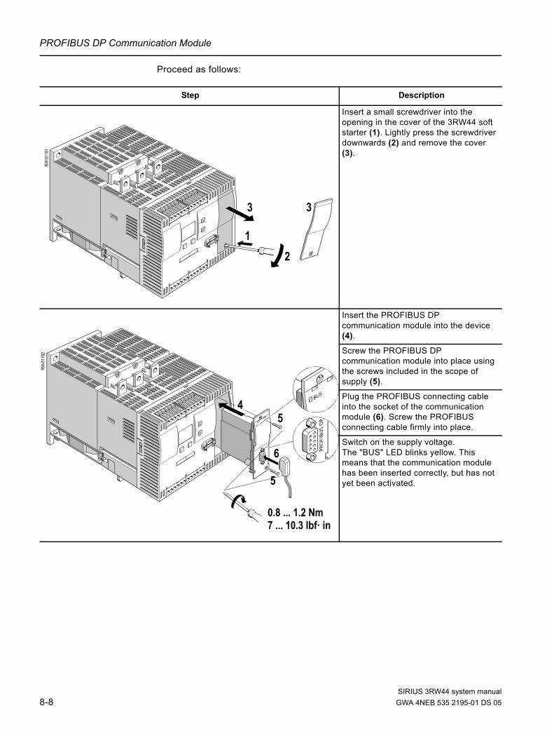
PROFIBUS DP Communication Module
Proceed as follows:
Step Description
Insert a small screwdriver into the opening in the cover of the 3RW44 soft starter (1). Lightly press the screwdriver downwards (2) and remove the cover (3).
Insert the PROFIBUS DP communication module into the device (4).
Screw the PROFIBUS DP communication module into place using the screws included in the scope of supply (5).
Plug the PROFIBUS connecting cable into the socket of the communication module (6). Screw the PROFIBUS connecting cable firmly into place.
Switch on the supply voltage. The "BUS" LED blinks yellow. This means that the communication module has been inserted correctly, but has not yet been activated.
12
3
RW-0
1181
3
5
5
6
4
RW-0
1182
0.8 ... 1.2 Nm7 ... 10.3 lbf· in
SIRIUS 3RW44 system manual8-8 GWA 4NEB 535 2195-01 DS 05

PROFIBUS DP Communication Module
8.4 Activating the PROFIBUS DP Communication Module (Field Bus Interface) and Setting the Station Address
8.4.1 Introduction
Activate the PROFIBUS DP communication module (device function "Field bus") and set the station address either via the display or via the device interface using the "Soft Starter ES Premium" or the "Soft Starter ES + SP1" software.
Notice After the communication module has been activated, the control priority automatically switches from the inputs to the PROFIBUS DP communication module. If an input is active with the "Manual operation local" function, the control priority does not change (refer to Chapter 5.4.7 "Parameterizing the Inputs" on Page 5-28).
The station address of the soft starters is pre-set to 126 as the factory default.
SIRIUS 3RW44 system manualGWA 4NEB 535 2195-01 DS 05 8-9

PROFIBUS DP Communication Module
8.4.2 Activating the PROFIBUS DP Communication Module via the Display, Setting the Station Address and Saving the Settings
1. When putting the soft starter into operation for the first time, you have to go through the quick start menu (refer to Chapter 5.2). Also refer to the operating instructions "3RW44 Soft Starters" (order number: 3ZX1012-0RW44-0AA0).
2. Press the respectively marked key on the device.
3. The "BUS" LED blinks red.4. When the PROFIBUS icon appears on the display, the PROFIBUS DP
communication module has been activated successfully.
Status
select
2
display
select
Settings
select
3
select
Parameter
select
1
select
set 1
Saving
select
11
select
options
Fieldbus
select
10
select
Fieldbus
select
1
change
interfaceOff
selectselect
Fieldbus interface12 On
Off
selectselect
Fieldbus interface12 On
Off
Fieldbus
select
1
change
interfaceOn
Display mea-
select
1
sured value
select
1
SIEMENS
Menu
3RW44
ESC OK
ESC OK
ESC OK
ESC OK
ESC OK
ESC OK
ESC OK
ESC OK
ESC OK
ESC OK
ESC OK
SIRIUS 3RW44 system manual8-10 GWA 4NEB 535 2195-01 DS 05

PROFIBUS DP Communication Module
The next step is to set the desired station address for the 3RW44 as a PROFIBUS slave. In this example, the station address is set to "23".
Notice If the parameter "Parameters disabled CPU/Master" is set to "Off" (factory setting), then the parameters set on the soft starter will be overwritten with the values stored in the GSD file or in the OM when the bus is started. If this is not desired, the parameter must be set to "On".
Fieldbus
select
1
change
interfaceOn
ESC OK
Group diagnosis
select
2
change
Disable
ESC OK
Response to 3
change
Substitute value
ESC OK
CPU master stop
Station address
selectexecute
23
Station address
select
4
change
23
ESC OK
ESC OK
Station address
selectexecute
126
ESC OK
Station address
select
4
change
126
ESC OK Adjustablefrom ... to
1... 126
Parameterization options
On, Off
Disable, enable
Substitute value, last value
Baud rate 5
12,000 kBd
Substitute value
select
6
select
Parameters
select
7
change
Off
ESC OK
disable CPU/Master
ESC OK
ESC OK
SIRIUS 3RW44 system manualGWA 4NEB 535 2195-01 DS 05 8-11

PROFIBUS DP Communication Module
5. In order to permanently save the settings, proceed as follows:
Notice If the parameter "Parameters disabled CPU/Master" is set to "Off" (factory setting) in the menu "Field bus", the parameters set on the soft starter will be overwritten with the values stored in the GSD data or in the OM when the bus is started. If this is not desired, the parameter must be set to "On".
Station address
select
4
change
23
ESC OK
Fieldbus
select
10
select
ESC OK
Saving
selectexecute
ESC OK
options
10
11
Function call
selectexecute
ESC OK
Save1
settings
Save
select
1
Yes
settingsexecute?
ESC OK
SIEMENS
Menu
3RW44
ESC OK
SIRIUS 3RW44 system manual8-12 GWA 4NEB 535 2195-01 DS 05

PROFIBUS DP Communication Module
8.4.3 Activating the PROFIBUS DP Communication Module (Field Bus Interface) and Setting the Station Address via the Device Interface using the "Soft Starter ES Premium" or the "Soft Starter ES + SP1" Software
Carry out the following steps to activate the communication module: 1. Use an interface cable to connect the 3RW44 soft starter to a PC on which the
"Soft Starter ES Premium" or the "Soft Starter ES + Service Pack 1" software is installed.
2. Start the "Soft Starter ES Premium" or "Soft Starter ES + Service Pack 1" software.
3. Select "Switching device > Open online" in the menu.4. In the "Open online" dialog box, select the "Local device interface" option and the
desired COM port under "Interface".5. Click "OK".6. Select "Device configuration" on the left-hand side of the window.7. Activate the "Field bus interface" control box on the right-hand side of the
window.
8. Select "Device parameters > Field bus" on the left-hand side of the window.
SIRIUS 3RW44 system manualGWA 4NEB 535 2195-01 DS 05 8-13

PROFIBUS DP Communication Module
9. Select your station address from the dropdown list box on the right-hand side of the window.
10.Select the "Load to Switching Device" icon in the tool bar.11.Confirm the station address change with "OK".12.Confirm the activation of the PROFIBUS DP communication module with "OK".
The PROFIBUS DP communication module has been activated.13.When the "BUS" LED on the communication module blinks red and the
PROFIBUS icon appears on the display, the communication module has been activated successfully.
NoticeThe soft starter only reads the station address automatically and permanently saves it when the supply voltage of the soft starter is switched on (refer to Chapter 8.6.5 "Flow Diagram PROFIBUS DP - Starting the Soft Starter" on Page 8-22) or following a "Restart" command.
SIRIUS 3RW44 system manual8-14 GWA 4NEB 535 2195-01 DS 05

PROFIBUS DP Communication Module
8.5 Soft Starter Configuration
8.5.1 Introduction
This section deals with the configuration and parameterization of soft starters.• Configuring: Systematic arrangement of the individual soft starters (structure).• Parameterization: Setting of the parameters using the configuration software.
Further information regarding parameters can be found in Chapter 8.10 "Data Formats and Data Sets" on Page 8-35.
STEP 7• The "Diagnose hardware" function is available with STEP 7 V5.1 from
correction version K5.1.2.0 onwards.• Reloading of the configuration is not supported in STEP 7
(Target system → Load to PD).• It is only possible to read the diagnosis via the CPU 315-2 DP
(using the "Diagnose hardware" function in STEP 7) up to order number 6ES7315–2AF02.
8.5.2 Configuration with the GSD File
Definition of the GSDThe device master data (GSD) contain DP slave descriptions in a uniform format. Use of the GSD simplifies the configuration of the DP master and the DP slave.
Configuration with the GSD FileSoft starters are configured using the GSD file. The soft starter is embedded into your system as a standard slave via the GSD file. You can download the GSD file
• from the Internet at http://support.automation.siemens.com/WW/view/en/113630
The following GSD files are available:• SIEM80DE.GSG (German)• SIEM80DE.GSE (English)• SIEM80DE.GSF (French)• SIEM80DE.GSI (Italian)• SIEM80DE.GSS (Spanish)
Notice Your configuration tool must support GSD files - Rev.3, e.g. STEP 7 V5.1+Service Pack 2 and higher.
SIRIUS 3RW44 system manualGWA 4NEB 535 2195-01 DS 05 8-15

PROFIBUS DP Communication Module
8.5.3 Configuration with the Soft Starter ES Premium Software
Sirius 3RW44 soft starters can also be configured using the Soft Starter ES Premium software.There are two possibilities when using PROFIBUS DP:• Stand-alone program on a PC/PD with PROFIBUS DP connection• Integration with the object manager (OM) in STEP 7
Detailed information regarding Soft Starter ES can be found in the program's online help.
8.5.4 Diagnostics Package
A free diagnostics package is available for 3RW44 soft starters. It contains HMI diagnostic screens for touch panels. The diagnostics package is available in German and English. You can download the diagnostics package at:http://support.automation.siemens.com/WW/view/en/28557893
8.5.5 Soft Starter ES Parameterizing Software
Soft Starter ES is the central software for commissioning, operating and diagnosis of the SIRIUS 3RW44 High Feature soft starter series.
You can download the Soft Starter ES parameterizing software at http://support.automation.siemens.com/WW/view/en/28323168. This is a free 14-day trial version.
SIRIUS 3RW44 system manual8-16 GWA 4NEB 535 2195-01 DS 05

PROFIBUS DP Communication Module
8.6 PROFIBUS DP Commissioning using the GSD File in STEP 7 (Example)
8.6.1 Introduction
The following example shows you how to commission the PROFIBUS DP communication module.
• Installation and activation of the PROFIBUS DP communication module (field bus interface)
• Configuration with STEP 7 using the GSD file• Integration into the user program• Switching on
Necessary components• 3RW44 soft starter• 3RW49 00-0KC00 communication module
General prerequisites• You have configured an infeed module with integrated S7 station
e.g. with CPU315-2 DP.• You are proficient in STEP 7.• The PD is connected to the DP master.
Software prerequisites
Table 8-1: Software prerequisites for commissioning
Configuration software used Version Explanations
STEP 7 From version V5.1+SP2 onwards
You have integrated the GSD file of the soft starter into STEP 7.
Configuration software for the different DP master used
You have integrated the GSD file of the soft starter into the respective configuration tool.
SIRIUS 3RW44 system manualGWA 4NEB 535 2195-01 DS 05 8-17

PROFIBUS DP Communication Module
Prerequisites for commissioning
Table 8-2: Prerequisites for commissioning
Required actions For further information, refer to ...
1. The soft starter is installed Chapter 3 "Installation, Connection and Branch Layout" on Page 8-1
2. The PROFIBUS DP communication module is installed
Chapter 8.3 "Installation of the PROFIBUS DP Communication Module" on Page 8-7.
3. The station address is set on the soft starter Chapter 8.4.3 "Activating the PROFIBUS DP Communication Module (Field Bus Interface) and Setting the Station Address via the Device Interface using the "Soft Starter ES Premium" or the "Soft Starter ES + SP1" Software" on Page 8-13.
4. The soft starter has been configured (configured and parameterized)
Chapter 8.5 "Soft Starter Configuration" on Page 8-15
5. The supply voltage for the DP master is switched on
DP master manual
6. The DP master is switched to the operating state RUN
DP master manual
SIRIUS 3RW44 system manual8-18 GWA 4NEB 535 2195-01 DS 05

PROFIBUS DP Communication Module
8.6.2 Configuration using the Device Master Data (GSD) in STEP 7
Table 8-3: Commissioning
Step Description
1 Activate the PROFIBUS DP communication module as described in Chapter 8.4.
2 Set the desired station address as described in Chapter 8.4.
3 Switch on the supply voltage for the DP master CPU 315-2 DP at the infeed module.
4 Observe the status LEDs of the DP master CPU 315-2 DP on the infeed module:
5 V DC:SF DP:BUSF:
Lights upOffBlinking
5Start the SIMATIC Manager and create a new project with a DP master (e.g. CPU315-2 DP with DI 16 x24 V DC and DO 16 x24 V DC). Generate OB1 and OB82 for the project.
6
In HW config., call up the menu command Extras > Install new GSD file, and integrate the GSD file of the soft starter into the configuration tool of the DP master used. For the CPU315-2 used in the example, you can install• the German GSD file SIEM80DE.GSG,• the English GSD file SIEM80DE.GSE,• the French GSD file SIEM80DE.GSF,• the Spanish GSD file SIEM80DE.GSS,• the Italian GSD file SIEM80DE.GSIin the STEP 7 SIMATIC Manager.
7 Generate the PROFIBUS DP subnet.
8Add the soft starter from the hardware catalog to the PROFIBUS under PROFIBUS DP > Additional field devices > Switching devices > Motor starters > Direct on line soft starters > Sirius 3RW44.
9 Set the station address for the soft starter to 3 (or higher).
10
Drag the module from the selection list of the dropdown menu to slot 1 of the Sirius 3RW44:
Open the "DP slave characteristics" dialog with a double click.
11
Click on "Parameterization". Set the parameters **), e.g.
Rated operating current
Click "OK". The configuration is completed.
12 Save the configuration.
*) Depending on the structure
Slot Module/DP ID Order number I addr. O
addr. Comment
1 192 3RW4422-*BC** 2...3*) 2...3*)
..
..
SIRIUS 3RW44 system manualGWA 4NEB 535 2195-01 DS 05 8-19
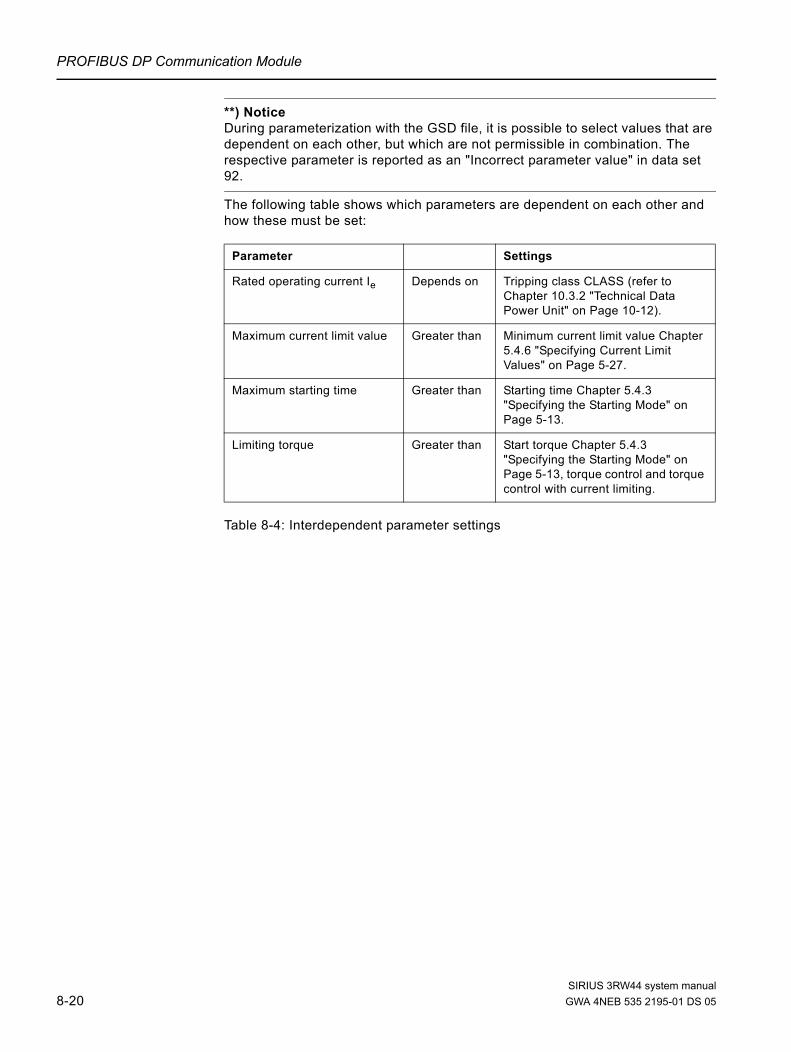
PROFIBUS DP Communication Module
**) Notice During parameterization with the GSD file, it is possible to select values that are dependent on each other, but which are not permissible in combination. The respective parameter is reported as an "Incorrect parameter value" in data set 92.
The following table shows which parameters are dependent on each other and how these must be set:
Table 8-4: Interdependent parameter settings
Parameter Settings
Rated operating current Ie Depends on Tripping class CLASS (refer to Chapter 10.3.2 "Technical Data Power Unit" on Page 10-12).
Maximum current limit value Greater than Minimum current limit value Chapter 5.4.6 "Specifying Current Limit Values" on Page 5-27.
Maximum starting time Greater than Starting time Chapter 5.4.3 "Specifying the Starting Mode" on Page 5-13.
Limiting torque Greater than Start torque Chapter 5.4.3 "Specifying the Starting Mode" on Page 5-13, torque control and torque control with current limiting.
SIRIUS 3RW44 system manual8-20 GWA 4NEB 535 2195-01 DS 05

PROFIBUS DP Communication Module
8.6.3 Integration into the User Program
Table 8-5: Integration into the User Program
8.6.4 Switching On
Table 8-6: Switching on
Step Description
1Create the user program in the LAD/STL/CSF editor in OB1.Example: Reading an input and controlling an output:
2 Save the project in the SIMATIC manager.
3 Load the configuration into the DP master.
Cyclically copy the central DIs (switches) to the decentralized motor starter (=PAA).Cyclically output the PAE of the motor starter to the central DOs (LED).
// PAA: read in switches 0-7 (DI 16 x 24 V DC) // y emitir al arrancador de motor
// EB0.0 Motor - RIGHT// EB0.1 Motor - LEFT// EB0.2 0
// Read in the motor starter PAE// and output to D016xDC24V
Step Description
1 Switch on the voltage supply for the soft starter.
2
Observe the status LEDs on the DP master CPU315-2 DP:
5 V DC: Lights up
SF DP: Off
BUSF: Off
3Observe the status LEDs on the PROFIBUS module:
LED BUS: Lights up green
SIRIUS 3RW44 system manualGWA 4NEB 535 2195-01 DS 05 8-21

PROFIBUS DP Communication Module
8.6.5 Flow Diagram PROFIBUS DP - Starting the Soft Starter
Figure 8-14:PROFIBUS DP - starting the soft starter
Remedy: Match the configuration data to the
structure or vice versa
Switch on the supply voltagefor the soft starter
The soft starter sets the outputs to "0" and accepts the set station
address
The soft starter receivesthe configuration data from the DP
master
The "BUS" LED lights up green;Inputs and outputs are enabled; data
exchange is possible
The "BUS" LED is red
No
Yes
Ready for operation
Do the configurationdata match the actual structure?
SIRIUS 3RW44 system manual8-22 GWA 4NEB 535 2195-01 DS 05

PROFIBUS DP Communication Module
8.7 Process Data and Process Images
Definition of the process imageThe process image is part of the system memory of the DP master. At the beginning of the cyclical program, the signal statuses of the inputs are transmitted to the process image of the inputs. At the end of the cyclical program, the process image of the outputs is transmitted to the DP slave as a signal status.
Soft starters with PROFIBUS DP have the following process image:• Process image with 2 byte outputs / 2 byte inputs (16 O / 16 I)
SIRIUS 3RW44 system manualGWA 4NEB 535 2195-01 DS 05 8-23

PROFIBUS DP Communication Module
TableThe following table contains process data and process images:
Table 8-7: Process data and process images
Param
eter set 1
Param
eter set 2
Param
eter set 3
Process im
age errorPS1 PS2 PS3
0 1 0 1
0 0 1 1
Process dataProcess image:
(16 O, DO 0.0 to DO 1.7)(16 I, DI 0.0 to DI 1.7)
Outputs
DO- 0. 0 Motor RIGHT
1 Motor LEFT
2 Available
3 Trip reset
4 Emergency start
5 Available
6 Slow speed
7 Available
DO- 1. 0 Output 1
1 Output 2
2 Parameter set Bit 0
3 Parameter set Bit 1
4 Available
5 Available
6 Available
7 Disable quick stop
Inputs
DI- 0. 0 Ready (automatic)
1 Motor on
2 Group error
3 Group warning
4 Input 1
5 Input 2
6 Input 3
7 Input 4
DI- 1. 0 Motor current Iact-bit0
1 Motor current Iact-bit1
2 Motor current Iact-bit2
3 Motor current Iact-bit3
4 Motor current Iact-bit4
5 Motor current Iact-bit5
6 Manual operation local operating mode
7 Ramp operation
SIRIUS 3RW44 system manual8-24 GWA 4NEB 535 2195-01 DS 05

PROFIBUS DP Communication Module
8.8 Diagnosis via LED Display
Table 8-8: Diagnosis via LED display
LED Description
BUS Red Bus error
Red blinking Parameter error
Red flickering Basic factory settings restored (red flickering for 5 sec)
Red-green toggling*)
Parameter error while starting S7
Green Device exchanging data!
Yellow Device not initialized and bus error! (Send in device!)
Yellow-green blinking
Device not initialized and parameter error! (Send in device!)
Off Device not exchanging data!
Specifications
Error: BE = Bus error
Frequency specifications:
Blinking: 0.5 Hz
Flickering: 8 to 10 Hz
*) Toggling: 2 to 10 Hz
SIRIUS 3RW44 system manualGWA 4NEB 535 2195-01 DS 05 8-25

PROFIBUS DP Communication Module
8.9 Diagnosis with STEP 7
8.9.1 Reading the Diagnosis
Length of the diagnosis telegramThe maximum length of the telegram is 32 byte.
8.9.2 Options for Reading the Diagnosis
Table 8-9: Reading the diagnosis with STEP 7
Reading the S7 diagnosis with SFC 13 "DP NRM_DG" (example)This is an example of how to read the slave diagnosis for a DP slave in the STEP 7 user program using SFC 13.
AssumptionsThe following assumptions are true for this STEP 7 user program:
• The diagnostic address is 1022 (3FEH).• The slave diagnosis should be stored in DB82: from address 0.0,
length 32 bytes.• The slave diagnosis consists of 32 bytes.
STEP 7 user program
Automation system with DP master
Module or register inSTEP 7 Application Refer to ...
SIMATIC S7/M7 SFC 13 "DP NRM_DG" Reading the slave diagnosis (store in data area of the user program)
Chapter 8.9.3 "Structure of the Slave Diagnosis" on Page 8-27, For SFC, refer to the online help in STEP 7
STL Explanation
CALL SFC 13
REQ :=TRUE
LADDR :=W#16#3FE
RET_VAL :=MW0
RECORD :=P#DB82.DBX 0.0 BYTE 32
BUSY :=M2.0
Read request
Diagnostic address
RET_VAL of SFC 13
Data compartment for diagnosis in DB82
Read operation runs over several OB1
cycles
SIRIUS 3RW44 system manual8-26 GWA 4NEB 535 2195-01 DS 05

PROFIBUS DP Communication Module
8.9.3 Structure of the Slave Diagnosis
Figure 8-15:Structure of the slave diagnosis
Notice The length of the diagnosis telegram varies between 13 and 32 bytes. The length of the diagnosis telegram last received can be seen in STEP 7 from the RET_VAL parameter of SFC 13.
...
...
Station status 1 to 3
Master PROFIBUS address
High byteLow byte Manufacturer code
Code-based diagnosis
Module status
Channel-based diagnosis(3 bytes per channel)
Byte 0Byte 1Byte 2
Byte 3
Byte 4Byte 5
Byte 8
Byte 12
...Byte 13Byte 14Byte 15...
up to max.Byte 31
Det
ails
(here: soft starter)
Byte 6Byte 7
SIRIUS 3RW44 system manualGWA 4NEB 535 2195-01 DS 05 8-27

PROFIBUS DP Communication Module
8.9.4 Station Status 1 to 3
DefinitionStation status 1 to 3 gives an overview of the status of aDP slave.
Station status 1
Table 8-10: Station status 1 structure (byte 0)
Bit Meaning Cause/Remedy
0 1: The DP slave cannot be addressed by the DP master.
• Has the station address been set correctly at the DP slave?• Is the bus connector connected?• Is voltage applied at the DP slave?• Is the RS 485 repeater set correctly?• Has a reset been carried out on the DP slave?
1 1: The DP slave is not yet ready for data exchange. • Wait, since the DP slave is just starting up.
2 1: The configuration data sent to the DP slave by the DP master do not match the structure of the DP slave.
• Has the correct station type or the correct structure for the DP slave been entered into the configuration software?
3 1: There is an external diagnosis. (Group diagnosis display)
• Analyze the code-based diagnosis, the module status and /or the channel-related diagnosis. As soon as all errors have
been remedied, bit 3 is reset. The bit is set again when a new diagnosis message is available in the bytes of the above mentioned diagnoses.
4 1: The requested function is not supported by the DP slave (e.g. changing of the station address via software).
• Check the configuration.
5 1: The DP master cannot interpret the reply from the DP slave. • Check the bus design.
6 1: The DP slave type does not match the software configuration.
• Has the correct station type been entered into the configuration software?
7 1: The DP slave was parameterized by a different DP master (not by the DP master accessing the DP slave at the moment).
• Bit is always 1 when you are accessing the DP slave with the PD or another DP master, for example. The station address of the DP master which carried out the parameterization of the DP slave can be found in the "Master PROFIBUS Address" diagnostic byte.
SIRIUS 3RW44 system manual8-28 GWA 4NEB 535 2195-01 DS 05

PROFIBUS DP Communication Module
Station status 2
Table 8-11: Station status 2 structure (byte 1)Station status 3
Table 8-12: Station status 3 structure (byte 2)
Bit Meaning
0 1: The DP slave must be newly parameterized.
1 1: There is a diagnosis message. The DP slave does not function until the error has been remedied (static diagnosis message).
2 1: The bit is always set to "1" when a DP slave with this station address exists.
3 1: The watchdog function is activated for this DP slave.
4 1: The DP slave has received the "FREEZE" command1).
5 1: The DP slave has received the "SYNC" command1).
6 0: Bit is always "0".
7 1: The DP slave has been deactivated, i.e. it is not part of the current processing.
1) The bit is only updated if another diagnosis message changes.
Bit Meaning
0 to 6 0: Bits are always "0".
7 1: • There are more diagnosis messages than the DP slave can store.• The DP master cannot write all diagnosis messages sent by the DP
slave in its diagnosis buffer (channel-based diagnosis).
SIRIUS 3RW44 system manualGWA 4NEB 535 2195-01 DS 05 8-29

PROFIBUS DP Communication Module
8.9.5 Master PROFIBUS Address
DefinitionThe master PROFIBUS address diagnostic byte stores the station address of the DP master: • which has carried out the parameterization of the DP slave and• has read and write access to the DP slave.
The master PROFIBUS address is in byte 3 of the slave diagnosis.
8.9.6 Manufacturer Code
DefinitionThe manufacturer code contains a code describing the type of DP slave.
Manufacturer code
Table 8-13: Structure of the manufacturer code
Byte 4 Byte 5 Manufacturer code for
80H DEH Soft starters
SIRIUS 3RW44 system manual8-30 GWA 4NEB 535 2195-01 DS 05

PROFIBUS DP Communication Module
8.9.7 Code-Based Diagnosis
DefinitionCode-based diagnosis indicates whether or not there are any faulty soft starters. The code-based diagnosis begins with byte 6 and comprises 2 bytes.
Code-based diagnosisThe structure of the code-based diagnosis for soft starters is as follows:
Figure 8-16:Structure of the code-based diagnosis
0 1 0 0 0 0 1 07 6 5 0
Byte 6Bit number
= 0x42
Length of the code-based diagnosisincluding byte 6 (=2 bytes)
Code for code-based diagnosis
0 0 0 0 0 0 0 x7 6 5 0
Byte 7Bit number
0: Channel-based diagnosis not available1: Channel-based diagnosis available
SIRIUS 3RW44 system manualGWA 4NEB 535 2195-01 DS 05 8-31

PROFIBUS DP Communication Module
8.9.8 Module Status
DefinitionThe module status reflects the status of the configured module (here: soft starter) and represents a specification of the code-based diagnosis. The module status starts after the code-based diagnosis and comprises 5 bytes.
Module status structureThe structure of the module status is as follows:
Figure 8-17:Structure of the module status
0 0 0 0 0 1 0 17 6 5 0
Byte 8Bit number
= 0x05
Length of the module statusincluding byte 8 (=5 bytes)
Code for module status
0 0 x7 6 5
Byte 12Bit number
7 0Byte 9 82H
7 0Byte 10 0H
Byte 11 0H
40
3 2 1 0
Not relevant
Not relevant
00B: Soft starter OK; valid user data01B: Soft starter error; invalid user data
SIRIUS 3RW44 system manual8-32 GWA 4NEB 535 2195-01 DS 05

PROFIBUS DP Communication Module
8.9.9 Channel-Based Diagnosis
DefinitionThe channel-based diagnosis provides information about channel errors of the modules (here: soft starter) and represents a specification of the code-based diagnosis. The channel-based diagnosis starts after the module status. The maximum length is restricted to the maximum overall length of the slave diagnosis, i.e. 31 bytes. The channel-based diagnosis does not affect the module status.The number of channel-based diagnosis messages is restricted to 9 (also refer to station status 3, bit 7).
Channel-based diagnosisThe structure of the channel-based diagnosis is as follows:
Figure 8-18:Structure of the channel-based diagnosis
NoticeThe channel-based diagnosis is always updated up to the current diagnosis message in the diagnosis telegram. Subsequent older diagnosis messages are not deleted. Remedy: Analyze the valid current length of the diagnosis telegram: • STEP 7 from the RET_VAL parameter of SFC 13.
1 0 0 0 0 0 0 07 6 5 0
Byte 13Bit number
Code for channel-based diagnosis
1 1 0 0 0 0 0 07 6 5 0
Byte 14Bit number
Input/output channel
7 6 5 0Byte 15
Bit number
Channel type:
Error type (table on the next page)
000B: No special channel type
Byte 16 to Next channel-based diagnosis message(same assignment as byte 13 to 15)
max. byte 31
Byte 18to
0 0 0
SIRIUS 3RW44 system manualGWA 4NEB 535 2195-01 DS 05 8-33

PROFIBUS DP Communication Module
Error typesThe diagnosis message is reported on channel 0.
Table 8-14: Error types
E No. Error type Meaning/Cause Delete signal bit / Acknowledgement
E1 00001:Short-circuit • Short-circuit in the temperature sensor
The signal bit is deleted automatically when the cause for the switch-off has been remedied and acknowledged via "Trip reset".
E4 00100: Overload
• Overload of the temperature sensor• Overload of the thermal motor model The signal bit is updated continuously.
E5 00101: Overtemperature • Overload of the contact block
The signal bit is deleted automatically when the cause for the switch-off has been remedied and acknowledged via "Trip reset".
E6 00110: Line breakage • Wire break in the temperature sensor
The signal bit is updated continuouslyE700111:Maximum limit value exceeded
• Ie limit value exceeded
E801000: Minimum limit value undershot
• Ie limit value undershot
E9 01001: Error
• Internal error/device error• Contact block defective
The signal bit can be deleted when the cause of the error has been remedied by• Switching the supply voltage off/on• Issuing the "Restart" command if possible
E16 10000: Parameter error • Incorrect parameter value The signal bit is always deleted after
acknowledgement with "Trip reset".
E1710001: No supply or load voltage
• Electronics supply voltage too low • No supply voltage at the contact block• No line voltage
The signal bit is deleted when the cause for the switch-off has been remedied or acknowledged automatically.
E2411000: Actuator switch-off
• Switch-off due to overload • Switch-off due to residual current • Switch-off due to asymmetry • Switch-off due to ground fault
The signal bit is always deleted after acknowledgement with "Trip reset".Additional acknowledgement in combination with other errors.
E26 11010: External error
• Overload of the sensor supply• Process image error
The signal bit is always deleted after acknowledgement with "Trip reset".
SIRIUS 3RW44 system manual8-34 GWA 4NEB 535 2195-01 DS 05

PROFIBUS DP Communication Module
8.10 Data Formats and Data Sets
8.10.1 Characteristics
The soft starter acquires a multitude of operating, diagnostics and statistics data.
Control dataData transmitted to the soft starter, e.g. Motor LEFT switching command, Trip reset, etc. Data format: Bit
MessagesData transmitted by the soft starter indicating the current operating status, e.g. Motor left, etc.Data format: Bit
DiagnosisData transmitted by the soft starter indicating the current operating status, e.g. Overload fault mode, etc.Data format: Bit
Current valuesCurrent values are coded in different current formats, in• 6-bit current format,• 8-bit current format and• 9-bit current format:
Figure 8-19:Current formats
Current values are• Motor current Imax (6-bit current format)• Phase currents IL1max, IL2max, IL3max (8-bit current format)• Last trigger current (9-bit current format)• Maximum tripping current (9-bit current format)
01245678 3
20 2-1 2-2 2-3 2-4 2-523 22 21
1 + 0.5 + 0.25 + 0.125 + 0.0625 + 0.03125 = 1.96875 (q 0 to 197 %)
8 + 4 + 2 1 + 0.5 + 0.25 + 0.125 + 0.0625 + 0.03125 = 15.97 (q 0 to 1597 %)
Bit
6-bit current format
4 + 2 1 + 0.5 + 0.25 + 0.125 + 0.0625 + 0.03125 = 7.97 (q 0 to 797 %)
8-bit current format
9-bit current format
SIRIUS 3RW44 system manualGWA 4NEB 535 2195-01 DS 05 8-35

PROFIBUS DP Communication Module
Statistics data for device service life• Operating hours
The soft starter records 2 operating hour values:– The motor operating hours.
These indicate how long the motor has been switched on.– The device operating hours (soft starter).
These indicate how long the 115 V AC or 230 V AC supply voltage of the soft starter has been switched on. Both operating hour values are recorded in data set 95 - "Read statistics". They are recorded in the "Operating hours" data field once every second. The operating hours are recorded in the range of 0 to 232 seconds in1-second increments.
• Number of overload tripsThe soft starter counts the number of overload trips in the range of 0 to 65535.
• Number of starts motor right / left The soft starter counts the number of starts in the range of 0 to 232.Example: The value is increased by 1 when current is flowing in the main circuit following a "Motor ON" command.
• Number of starts, outputs 1 to 4• Motor current Imax.
The soft starter measures the current in all 3 phases and indicates the current of the phase with the highest load as a percentage [%] of the set current Ie. Data format: 1 byte, 8-bit current formatExample: Set current Ie = 60 A Indicated motor current 110 % corresponds to 60 A x 1.1 = 66 A All 3 phase currents are available in data set 94
• Last trigger currentThe soft starter measures the current in all 3 phases and indicates the current flowing through the phase with the highest load at the time of the tripping as a percentage [%] of the set current Ie and in amperes [A] Data format: 2 byte, 9-bit current formatExample: Set current Ie = 60 A indicated motor current 455 % corresponds to 60 A x 4.55 = 273 A
SIRIUS 3RW44 system manual8-36 GWA 4NEB 535 2195-01 DS 05

PROFIBUS DP Communication Module
Statistics data of the maximum pointerMaximum pointers are used for preventive diagnosis:
– The maximum measured value is stored in the device. – The higher-level PLC can collect the measured value at any time.– The higher-level PLC can delete the measured value at any time.
The following data are available as maximum pointers:• Number of overload trips.• Phase current IL1max to IL3max and IL1min to IL3min. The maximum and
minimum phase current are indicated as a percentage [%] of the set current Ie and in amperes [A].Data format: Each 1 byte, 8-bit current format.The measured maximum and minimum phase current in bridging mode is stored for each phase.
• Minimum and maximum phase-to-phase voltages ULx - ULy as r.m.s values in 0.1 V. Minimum and maximum line frequency in 0.5 Hz resolution.
SIRIUS 3RW44 system manualGWA 4NEB 535 2195-01 DS 05 8-37

PROFIBUS DP Communication Module
8.11 Identification Number (ID No.), Error Codes
8.11.1 Identification Number (ID No.)
The identification number (ID No.) is used for the unique identification of all information available in the soft starter (parameters, control commands, diagnosis, commands, etc.). It can be found in the left column of the data set table.
8.11.2 Error Codes for Negative Data Set Acknowledgement
DescriptionWhen a data set is declined, an error code is sent together with the negative acknowledgement via the device interface as well as via the bus interface. The error code provides information on the reason for the negative acknowledgement.The error codes comply with the PROFIBUS DPV1 standard in so far as they apply to soft starters.
Analysis via the local device interface using Soft starter ESThe error codes are analyzed by the "Soft Starter ES" parameterizing and diagnostics software and output as plain text. For further information on this topic, please refer to the "Soft Starter ES" online help.
Analysis via PROFIBUS DPThe error codes are output via PROFIBUS DP layer 2. For further information on this topic, please refer to the section describing the PROFIBUS DP protocol in the respective manuals.
SIRIUS 3RW44 system manual8-38 GWA 4NEB 535 2195-01 DS 05

PROFIBUS DP Communication Module
Error codesThe following error codes are generated by the soft starter:
Table 8-15: Error codes
Error codes byte Error message Cause
High Low
00 H 00 H No error
Communication interface
80 H A0 H Negative acknowledgement"Read data set"
• Data set can only be written
80 H A1 H Negative acknowledgement"Write data set"
• Data set can only be read
80 H A2 H Protocol error • Layer 2 (field bus)• Device interface• Incorrect coordination
80 H A9 H This function is not supported! • DPV1 service does not support reading/writing of the data set
Technology access
80 H B0 H Unknown data set number • Data set number not known in the soft starter
80 H B1 H Incorrect data set length when writing • Data set length differs from data set length specified
80 H B2 H Incorrect slot number • Slot number not 1 or 4
80 H B6 H Communication partner declined data acceptance!
• Incorrect operating mode (automatic, manual bus, manual operation local)
• Data set can only be read• Parameter changes not
permissible when ON
80 H B8 H Invalid parameter • Incorrect parameter value
Device resources
80 H C2 H Temporary lack of resources in the device!
• No available receive buffer• The data set is currently being
updated• The data set order is currently
active at another interface
SIRIUS 3RW44 system manualGWA 4NEB 535 2195-01 DS 05 8-39

PROFIBUS DP Communication Module
8.12 Data Sets
Writing/reading data sets with STEP 7You can access the soft starter data sets via the user program.• Writing data sets:
S7-DPV1 master: By calling up SFB 53 "WR_REC" or SFC 58 S7 master: By calling up SFC 58
• Reading data sets: S7-DPV1 master: By calling up SFB 52 "RD_REC" or SFC 59 S7 master: By calling up SFC 59
Further informationFor further information regarding SFBs, please refer to• the reference manual
"System software for S7-300/400, System and Standard Functions"• in the STEP 7 online help
Byte arrangementsWhen data are stored which are longer than one byte, the bytes are arranged as follows ("big endian")
Table 8-16: Byte arrangement in "big endian" format
Byte arrangement Data type
Byte 0 High byte High word Double word
Byte 1 Low byte
Byte 2 High byte Low word
Byte 3 Low byte
Byte 0 High byte Word
Byte 1 Low byte
Byte 0 Byte 0 Byte
Byte 1 Byte 1
SIRIUS 3RW44 system manual8-40 GWA 4NEB 535 2195-01 DS 05

PROFIBUS DP Communication Module
8.12.1 Data Set 68 - Reading/Writing the Process Image of the Outputs
NotePlease keep in mind that data set 68 is overwritten by the cyclical process image in automatic operating mode!
Table 8-17: Data set 68 - reading/writing the process image of the outputs
In the "Automatic operating mode", the PLC specifies the process image of the outputs. In this case, reading of data set 68 at the local device interface supplies the process image of the outputs as transmitted by the PLC.
Byte Meaning
Preamble
0 Writing coordination 0x20 via channel C1 (PLC)Writing 0x30 via channel C2 (PC) Writing 0x40 via device interface (PC)
1 - 3 Reserved = 0
Process image of the outputs
4 Process data DO-0.0 to DO-0.7, table below
5 Process data DO-1.0 to DO-1.7, table below
6 Reserved = 0
7 Reserved = 0
ID No. Process data Process image: (16 A (outputs), DO 0.0 to DO 1.7)
1001 DO- 0. 0 Motor RIGHT
1002 1 Motor LEFT
1003 2 Available
1004 3 Trip reset
1005 4 Emergency start
1006 5 Available
1007 6 Slow speed
1008 7 Available
1009 DO- 1. 0 Output 1
1010 1 Output 2
1011 2 Parameter set Bit 0
1012 3 Parameter set Bit 1
1013 4 Available
1014 5 Available
1015 6 Available
1016 7 Disable quick stop
SIRIUS 3RW44 system manualGWA 4NEB 535 2195-01 DS 05 8-41

PROFIBUS DP Communication Module
8.12.2 Data Set 69 - Reading the Process Image of the Inputs
Table 8-18: Data set 69 - reading the process image of the inputs
Byte Meaning
Process image of the inputs
0 Process data DI-0.0 to DI-0.7, table below
1 Process data DI-1.0 to DI-1.7, table below
2 Reserved = 0
3 Reserved = 0
ID No. Process data Process image:
(16 I (inputs), DI 0.0 to DI 1.7)
1101 DI- 0. 0 Ready (automatic)
1102 1 Motor on
1103 2 Group error
1104 3 Group warning
1105 4 Input 1
1106 5 Input 2
1107 6 Input 3
1108 7 Input 4
1109 DI- 1. 0 Motor current Iact-bit0
1110 1 Motor current Iact-bit1
1111 2 Motor current Iact-bit2
1112 3 Motor current Iact-bit3
1113 4 Motor current Iact-bit4
1114 5 Motor current Iact-bit5
1115 6 Manual operation local operating mode
1116 7 Ramp operation
SIRIUS 3RW44 system manual8-42 GWA 4NEB 535 2195-01 DS 05

PROFIBUS DP Communication Module
8.12.3 Data Set 72 - Log List - Reading Device Errors
Table 8-19: Data set 72 - log list - reading device errors
This data set can record 21 entries. When all spaces are filled, the first entry is overwritten.
NoteThe latest entry is entered at the end of the data set. The remaining entries are moved up by one entry.
The following messages can be entered:
Byte Meaning Value range Increment Comment
0 - 3 Operating hours - device 1 ... 232 s 1 second Oldestentry4 - 5 ID number of the device
error0 ... ± 32,767 1
6 - 9 Operating hours - device 1 ... 232 s 1 second Second oldestentry10 - 11 ID number of the device
error0 ... ± 32,767 1
etc.
120 - 123 Operating hours - device 1 ... 232 s 1 second Last,newest entry124 - 125 ID number of the tripping 0 ... ± 32,767 1
ID No. Device error - Messages
452 Heatsink - thermistor defective
1466 Switching element 1 failed
1467 Switching element 2 failed
1468 Switching element 3 failed
1417 Bypass element fault
SIRIUS 3RW44 system manualGWA 4NEB 535 2195-01 DS 05 8-43

PROFIBUS DP Communication Module
8.12.4 Data Set 73 Log List - Reading the Trippings
Table 8-20: Data set 73 - log list - reading the trippings
This data set can record 21 entries. When all spaces are filled, the first entry is overwritten.
NoteThe latest entry is entered at the end of the data set. The remaining entries are moved up by one entry.
Byte Meaning Value range Increment Comment
0 - 3 Operating hours - device 1 ... 232 s 1 secondOldest entry4 - 5 ID number of the device
error0 ... ± 32,767 1
6 - 9 Operating hours - device 1 ... 232 s 1 second Second oldest entry10 - 11 ID number of the device
error0 ... ± 32,767 1
etc.
120 - 123 Operating hours - device 1 ... 232 s 1 second Last,newest entry124 - 125 ID number of the tripping 0 ... ± 32,767 1
SIRIUS 3RW44 system manual8-44 GWA 4NEB 535 2195-01 DS 05

PROFIBUS DP Communication Module
The following messages can be entered:
Table 8-21: Log list messages - reading the trippings
ID No. Trippings - Messages
309 Contact block overload
317 Electronics supply voltage too low
319 No line voltage
324 Temperature sensor overload
325 Temperature sensor open
326 Temperature sensor short-circuit
327 Thermal motor model overload
334 Ie limit value exceeded
335 Ie limit value undershot
339 Motor stalled - switched off
341 Asymmetry switch-off
343 Ground fault switch-off
355 Process image error
365 Incorrect parameter value
ID number of the faulty parameter
1407 Electronics supply voltage too high
1408 No load
1409 Loss of phase L1
1410 Loss of phase L2
1411 Loss of phase L3
1421 Impermissible Ie / CLASS settings
1479 Phase angle control failure
1481 Line voltage too high
1482 Current range exceeded
SIRIUS 3RW44 system manualGWA 4NEB 535 2195-01 DS 05 8-45

PROFIBUS DP Communication Module
8.12.5 Data Set 75 Log List - Reading Events
Table 8-22: Data set 75 log list - reading events
This data set can record 21 entries. When all spaces are filled, the first entry is overwritten.
NoteThe latest entry is entered at the end of the data set. The remaining entries are moved up by one entry.
Byte Meaning Value range Increment Comment
0 - 3 Operating hours - device 1 ... 232 s 1 second Oldestentry4 - 5 ID number of the device
error0 ... ± 32,767 *) 1
6 - 9 Operating hours - device 1 ... 232 s 1 second Second oldest entry10 - 11 ID number of the device
error0 ... ± 32,767 *) 1
etc.
120 - 123 Operating hours - device 1 ... 232 s 1 second Last,newest entry
124 - 125 ID number of the tripping 0 ... ± 32,767 *) 1
*) + coming event
– going event
SIRIUS 3RW44 system manual8-46 GWA 4NEB 535 2195-01 DS 05

PROFIBUS DP Communication Module
The following messages can be entered:
Table 8-23: Log list messages - reading events
ID No. Events - Messages Comment
Warnings
324 Temperature sensor overload ± (coming/going event)
325 Temperature sensor open ± (coming/going event)
326 Temperature sensor short-circuit ± (coming/going event)
327 Thermal motor model overload ± (coming/going event)
334 Ie limit value exceeded ± (coming/going event)
335 Ie limit value undershot ± (coming/going event)
340 Asymmetry recognized ± (coming/going event)
342 Ground fault ± (coming/going event)
Actions
310 Emergency start is active ± (coming/going event)
357 Automatic operating mode + (coming event only)
358 Manual bus operating mode + (coming event only)
359 Manual operation local operating mode + (coming event only)
360 Connection break in manual operating mode
± (coming/going event)
363 Maximum pointer deleted + (coming event only)
365 Incorrect parameter value + (coming event only)
ID number of the faulty parameter + (coming event only)
366 Parameter changes not permissiblewhen ON
+ (coming event only)
ID number of the faulty parameter + (coming event only)
368 Parameterization disable CPU/master active
± (coming/going event)
369 Basic factory settings restored + (coming event only)
1302 Log list - trippings deleted + (coming event only)
1303 Log list - events deleted + (coming event only)
SIRIUS 3RW44 system manualGWA 4NEB 535 2195-01 DS 05 8-47

PROFIBUS DP Communication Module
8.12.6 Data Set 81 - Reading the Basic Settings of Data Set 131
Data set 81 matches data set 131 in structure and content. Data set 81 supplies the default values for all parameters of data set 131.
8.12.7 Data Set 82 - Reading the Basic Settings of Data Set 132
Data set 82 matches data set 132 in structure and content. Data set 82 supplies the default values for all parameters of data set 132.
8.12.8 Data Set 83 - Reading the Basic Settings of Data Set 133
Data set 83 matches data set 133 in structure and content. Data set 83 supplies the default values for all parameters of data set 133.
SIRIUS 3RW44 system manual8-48 GWA 4NEB 535 2195-01 DS 05

PROFIBUS DP Communication Module
8.12.9 Data Set 92 - Reading the Device Diagnosis
ID No. ByteBit Signal bit E
No.*) Meaning/Acknowledgment
Switching/controlling:
301 00 Ready (automatic) — Device ready for operation via host (e.g. PLC). The signal bit is updated continuously.
306 01 Motor right — Contact block 1 switched on.The signal bit is updated continuously.
307 02 Motor left — Contact block 2 switched on.The signal bit is updated continuously.
309 03 Contact block overload E5,E24
For example, power semiconductor too hot, causing the motor to switch off.The signal bit is deleted when the cause for the switch-off has been remedied and acknowledged via "Trip reset".
308 04 Contact block defective E9 For example, contactor welded/blocked or power semiconductor short-circuited. The signal bit can only be deleted by switching the supply voltage off / on when the cause of error is remedied.
310 05 Emergency start is active — The signal bit is deleted when the emergency start is deactivated.
302 06 Group error — At least one error is set which generates an error number. The signal bit is deleted when the cause for the switch-off has been remedied and acknowledged via "Trip reset", autoreset or OFF command.
304 07 Group warning — At least one warning is pending.The signal bit is updated continuously.
10 Reserved = 0 —
319 11 No line voltage E17,E24
The signal bit is deleted when the cause for the switch-off has been remedied and acknowledged via "Trip reset".
12 Reserved = 0 —
312 13 Start mode active —The signal bit is updated continuously.
313 14 Stopping mode active —
15 Reserved = 0 —
316 16 Electrical braking procedure is active
— The braking output is switched on by the soft starter.The signal bit is updated continuously.
314 17 Slow speed active — The signal bit is updated continuously.
Protective function: Motor/line/short-circuit
324 20 Temperature sensor overload E4 Overload recognized, the signal bit is updated continuously.
325 21 Temperature sensor open E6 The thermistor circuit has been interrupted.The signal bit is updated continuously.
326 22 Temperature sensor short-circuit E1 Short-circuit in the thermistor circuit.The signal bit is updated continuously.
SIRIUS 3RW44 system manualGWA 4NEB 535 2195-01 DS 05 8-49
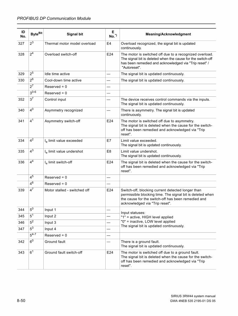
PROFIBUS DP Communication Module
327 23 Thermal motor model overload E4 Overload recognized, the signal bit is updated continuously.
328 24 Overload switch-off E24 The motor is switched off due to a recognized overload. The signal bit is deleted when the cause for the switch-off has been remedied and acknowledged via "Trip reset" /"Autoreset".
329 25 Idle time active — The signal bit is updated continuously.
330 26 Cool-down time active — The signal bit is updated continuously.
27 Reserved = 0 —
30-6 Reserved = 0 —
352 37 Control input — The device receives control commands via the inputs.The signal bit is updated continuously.
340 40 Asymmetry recognized — There is asymmetry. The signal bit is updated continuously.
341 41 Asymmetry switch-off E24 The motor is switched off due to asymmetry.The signal bit is deleted when the cause for the switch-off has been remedied and acknowledged via "Trip reset".
334 42 Ie limit value exceeded E7 Limit value exceeded.The signal bit is updated continuously.
335 43 Ie limit value undershot E8 Limit value undershot.The signal bit is updated continuously.
336 44 Ie limit switch-off E24 The signal bit is deleted when the cause for the switch-off has been remedied and acknowledged via "Trip reset".
45 Reserved = 0 —
46 Reserved = 0 —
339 47 Motor stalled - switched off E24 Switch-off, blocking current detected longer than permissible blocking time. The signal bit is deleted when the cause for the switch-off has been remedied and acknowledged via "Trip reset".
344 50 Input 1 —Input statuses: "1" = active, HIGH level applied"0" = inactive, LOW level appliedThe signal bit is updated continuously.
345 51 Input 2 —
346 52 Input 3 —
347 53 Input 4 —
54-7 Reserved = 0 —
342 60 Ground fault — There is a ground fault.The signal bit is updated continuously.
343 61 Ground fault switch-off E24 The motor is switched off due to a ground fault.The signal bit is deleted when the cause for the switch-off has been remedied and acknowledged via "Trip reset".
ID No. ByteBit Signal bit E
No.*) Meaning/Acknowledgment
SIRIUS 3RW44 system manual8-50 GWA 4NEB 535 2195-01 DS 05

PROFIBUS DP Communication Module
353 62 Quick stop active E26,E24
The motor is switched off due to a quick stop. The signal bit is deleted when the cause for the switch-off has been remedied and acknowledged via "Trip reset".
63 Reserved = 0
361 64 Trip reset carried out — The signal bit is deleted by update or "Trip reset" in ready state.
362 65 Trip reset not possible — Cause for the switch-off is still present. The signal bit is deleted by update (new "Trip reset") or by "Trip reset" in ready state.
363 66 Maximum pointer deleted — The signal bit is always deleted after acknowledgement with "Trip reset".
317 67 Electronics supply voltage too low
— The signal bit is deleted automatically when the cause for the switch-off is remedied.
Communication
303 70 Bus error — Watchdog function of the DP interface has elapsed.The signal bit is updated continuously.
356 71 CPU/master STOP — PLC program no longer processed.The signal bit is updated continuously.
357 72 Automatic operating mode — Automatic (PLC-controlled).The signal bit is updated continuously.
358 73 Manual bus operating mode — Manual operation via field bus (O&M controlled).The signal bit is updated continuously.
359 74 Manual operation local operating mode
— Manual operation via local device interface (O&M controlled). The signal bit is updated continuously.
75 Reserved = 0 —
360 76 Connection breakin manual operation local operating mode
— The associated communication connection was interrupted during manual operation. The signal bit is updated continuously.
355 77 Process image error E26 E24
Process image of the outputs contains impermissible bit combinations. The signal bit is automatically deleted when the cause for the switch-off is remedied.
Parameter
364 80 Parameterization active — The signal bit is updated continuously.
365 81 Incorrect parameter value E16 The signal bit is always deleted following an acknowledgement with "Trip reset" or after valid parameters have been received.
E24 Causes a switch-off during starting.
366 82 Parameter changes not permissible when ON
— Parameter change attempted while motor running or during the affected device function, causing a switch-off.The signal bit is always deleted following an acknowledgement with "Trip reset" or after valid parameters have been received.
368 83 Parameterization disable CPU/master active
— The signal bit is updated continuously.The soft starter ignores the parameters from the PLC.
84-7 Reserved = 0 —
ID No. ByteBit Signal bit E
No.*) Meaning/Acknowledgment
SIRIUS 3RW44 system manualGWA 4NEB 535 2195-01 DS 05 8-51

PROFIBUS DP Communication Module
Device function
90-2 Reserved = 0 —
369 93 Basic factory settings restored — The signal bit is always deleted after acknowledgement with "Trip reset".
94-7 Reserved = 0 —
367 10 Faulty parameter number (low byte) — In connection with byte 81 and 82, states the ID number of the first parameter not accepted.The signal byte is always deleted after acknowledgement with "Trip reset".
11 Faulty parameter number (high byte)
—
120-1 Reserved = 0 —
1421 122 Impermissible Ie/CLASS settings —
123-7 Reserved = 0 —
1449 130 Parameter set 1 active —
1450 131 Parameter set 2 active —
1451 132 Parameter set 3 active —
133 Reserved = 0 —
1453 134 Impermissible change of the parameter set
—
135-7 Reserved = 0 —
140-1 Reserved = 0 —
1404 142 Motor heating active —
1402 143 DC braking active —
1403 144 Dynamic DC braking active —
1471 145 Motor connection method star/delta —
1472 146 Motor connection method inside delta
—
1473 147 Motor connection method unknown —
1408 150 No load —
151 Reserved = 0 —
1409 152 Loss of phase L1 —
1410 153 Loss of phase L2 —
1411 154 Loss of phase L3 —
1412 155 Line phase direction right —
1413 156 Line phase direction left —
157 Reserved = 0 —
16 Reserved = 0 —
1435 170 Output 1 active —
1436 171 Output 2 active —
1437 172 Output 3 active —
1438 173 Output 4 active —
ID No. ByteBit Signal bit E
No.*) Meaning/Acknowledgment
SIRIUS 3RW44 system manual8-52 GWA 4NEB 535 2195-01 DS 05

PROFIBUS DP Communication Module
174-7 Reserved = 0 —
18 Reserved = 0 —
Switching/controlling
1407 190 Electronics supply voltage too high —
1470 191 Ready for motor on —
1414 192 Contact block short-circuited —
1417 193 Bypass element fault —
1418 194 Reserved = 0 —
1466 195 Switching element 1 failed —
1467 196 Switching element 2 failed —
1468 197 Switching element 3 failed —
Protective function
1422 200 Thermal motor model deactivated —
201-2 Reserved = 0 —
1479 203 Phase angle control failure —
204-7 Reserved = 0 —
1415 210 Cool-down time contact block active —
1416 211 Contact element too hot for starting —
1482 212 Current range exceeded —
213-7 Reserved = 0 —
Communication
357 220 Automatic operating mode (redundant to bit 7.2)
—
358 221 Manual bus operating mode (redundant to bit 7.3)
—
1443 222 Manual bus - PC-controlled —
359 223 Manual operation local operating mode (redundant to bit 7.4)
—
1444 224 Manual operation local - input-controlled
—
1445 225 Manual operation local - O&M-controlled
—
1446 226 Manual operation local - PC-controlled
—
227 Reserved = 0 —
23 Reserved = 0 —
ID No. ByteBit Signal bit E
No.*) Meaning/Acknowledgment
SIRIUS 3RW44 system manualGWA 4NEB 535 2195-01 DS 05 8-53

PROFIBUS DP Communication Module
Table 8-24: Data set 92 - reading the device diagnosis
*) Error numbers, PROFIBUS DP
Prewarnings
240-1 Reserved = 0 —
1419 242 Prewarning limit - remaining time for tripping undershot
—
1420 243 Prewarning limit - motor heat build-up exceeded
—
244-7 Reserved = 0 —
25 Reserved = 0 —
26 Reserved = 0 —
27 Reserved = 0 —
28 Reserved = 0 —
29 Reserved = 0 —
ID No. ByteBit Signal bit E
No.*) Meaning/Acknowledgment
SIRIUS 3RW44 system manual8-54 GWA 4NEB 535 2195-01 DS 05

PROFIBUS DP Communication Module
8.12.10 Data Set 93 - Writing a Command
Structure of the command data set
Table 8-25: Structure of the command data set
Table 8-26: Data set 93 - writing a command
Byte Meaning Comment
Preamble
0 Coordination Writing 0x20 via channel C1 (PLC) Writing 0x30 via channel C2 (PC) Writing 0x40 via device interface (PC)
1 - 3 Reserved
Command
4 Number of commands Value range 1 ... 5 Number of subsequent valid commands
5 Command 1 For the consecutive number, refer to the table below
6 Command 2 Optional (for coding, refer to the table below)
7 Command 3 Optional (for coding, refer to the table below)
8 Command 4 Optional (for coding, refer to the table below)
9 Command 5 Optional (for coding, refer to the table below)
ID No. Coding Command Meaning
1-byte commands
0 0 Reserved No function
703 1 Trip reset Reset and acknowledgement of error messages
713 2 Emergency start ON Switch on emergency start
714 3 Emergency start OFF Switch off emergency start
709 4 Automatic operating mode Transition to automatic operating mode (DP master-controlled)
710711712
5 Operating mode manual- bus - operation local
Transition to manual operating mode. The soft starter switches to manual bus or manual operation local operating mode, depending on the interface via which the command is received.
701 6 Restore basic factory settings
Restore basic factory settings of the parameters.
704 7 Delete maximum pointer The measured values for the preventive diagnosis are deleted (=0).
705 13 Log list - delete trippings
Delete log list with recorded causes of errors.
706 14 Log list - delete events
Delete log list with recorded warning messages and certain actions.
702 9 Restart Trigger restarting (same as after line ON), e.g. after reassigning the station address.
707 10 Parameterization disable CPU/master ON
No parameterization possible via the parameterizing master, or this master's parameters are ignored.
708 11 Parameterization disable CPU/master OFF
Parameterization possible via the parameterizing master.
SIRIUS 3RW44 system manualGWA 4NEB 535 2195-01 DS 05 8-55

PROFIBUS DP Communication Module
8.12.11 Data set 94 - Reading the Measured Values
Table 8-27: Data set 94 - Reading the Measured Values
ID No. ByteBit Meaning Value range / [coding] Increment Comment
Measured values
504 0 Phase current IL1 (%) 0 ... 797 % / [0 ... 255] 3.125 % 8-bit current format
505 1 Phase current IL2 (%) 0 ... 797 % / [0 ... 255] 3.125 % 8-bit current format
506 2 Phase current IL3 (%) 0 ... 797 % / [0 ... 255] 3.125 % 8-bit current format
507 3 Reserved = 0
501 4 - 5 Remaining cool-down time of the motor 0 ... 1,800 s / [0 ... 18 ,000] 0.1 s
50260-6 Motor heat build-up 0 ... 200 % / [0 ... 100] 2 %
67 Asymmetry ≥ 40 % No asymmetry [0]Asymmetry (≥ 40 %) [1]
503 7 Asymmetry 0 ... 100 % / [0 ...100] 1 %
8 Reserved = 0
9 Reserved = 0
10 Reserved = 0
11 Reserved = 0
12 - 13 Reserved = 0
14 Reserved = 0
508 16 Output frequency 0 ... 100 Hz / [0 ... 200] 0.5 Hz
17 Reserved = 0
18 Reserved = 0
19 Reserved = 0
509 20 Line frequency 0 ... 100 Hz / [0 ... 200] 0.5 Hz
21 Reserved = 0
510 22 - 23 Phase-to-phase voltage UL1-L2 (rms) 0 ... 1,500 V / [0 ... 15,000] 0.1 V
511 24 - 25 Phase-to-phase voltage UL2-L3 (rms) 0 ... 1,500 V / [0 ... 15,000] 0.1 V
512 26 - 27 Phase-to-phase voltage UL3-L1 (rms) 0 ... 1,500 V / [0 ... 15,000] 0.1 V
513 28 - 31 Phase current IL1 (rms) 0 ... 20,000 A / [0 ... 2,000 ,000] 0.01 A
514 32 - 35 Phase current IL2 (rms) 0 ... 20 ,000 A / [0 ... 2 ,000 ,000] 0.01 A
515 36 - 39 Phase current IL3 (rms) 0 ... 20,000 A / [0 ... 2 ,000,000] 0.01 A
516 40 - 41 Electronics supply voltage 0 ... 1,500 V / [0 ... 15,000] 0.1 V
517 42 Heatsink temperature -40 ... 127 °C/ [-40 ... 127] 1 °C
518 43 Contact block temperature 0 ... 250 °C/ [0 ... 250] 1 °C
519 44 - 45 Remaining cool-down time of thecontact block
0 ... 1 ,800 s / [0 ... 18,000] 0.1 s
520 46 - 47 Remaining time for tripping of thethermal motor model
0 ... 10,000 s / [0 ... 10,000] 1 s
521 48 - 51 Output power 0 ... 2 ,147,483 W / [0 ... 21 ,474 ,830] 0.1 W
522 52 - 63 Reserved = 0
SIRIUS 3RW44 system manual8-56 GWA 4NEB 535 2195-01 DS 05

PROFIBUS DP Communication Module
8.12.12 Data Set 95 - Reading the Statistics Data
Table 8-28: Data set 95 - reading the statistics data
ID No. ByteBit Meaning Value range / [coding] Increment Comment
Statistics
609 0 Motor current Imax 0 ... 797 % / [0 ... 255] 3.125 % 8-bit current format
1 Reserved = 0
608 2 Last trigger current IA (%) 0 ... 1,000 % / [0 ... 320] 3.125 %
4 Operating hours - device 0 ... 232-1 s / [0 ... 232-1] 1 s
603 8 - 11 Number of starts motor right 0 ... 232-1 / [0 ... 232-1] 1
604 12 - 15 Number of starts motor left 0 ... 232-1 / [0 ... 232-1] 1
605 16 - 17 Number of overload trips 0 ... 65 ,535 / [0 ... 65,535] 1
18 Reserved = 0
19 Reserved = 0
607 20 Motor current Imax (rms) 0 ... 20 ,000 A / [0 ... 2,000 ,000] 0.01 A
606 24 Last trigger current IA (rms) 0 ... 20,000 A / [0 ...2,000 ,000] 0.01 A
602 28 Operating hours - motor 0 ... 232-1 s / [0 ... 232-1] 1 s
611 32 Operating hours - motor current 18 ... 49.9 % x Ie(max)
0 ... 232-1 s / [0 ... 232-1] 1 s
612 36 Operating hours - motor current 50 ... 89.9 % x Ie(max)
0 ... 232-1 s / [0 ... 232-1] 1 s
613 40 Operating hours - motor current 90 ... 119.9 % x Ie(max)
0 ... 232-1 s / [0 ... 232-1] 1 s
614 44 Operating hours - motor current 120 ... 1,000 % x Ie(max)
0 ... 232-1 s / [0 ... 232-1] 1 s
615 48 Reserved = 0
616 50 Number of contact block overload trips
0 ... 232-1 / [0 ... 232-1] 1
617 52 Reserved = 0
618 54 Reserved = 0
619 56 Reserved = 0
620 60 Number of braking stops 0 ... 232-1 / [0 ... 232-1] 1
621 64 Number of starts - output 1 0 ... 232-1 / [0 ... 232-1] 1
622 68 Number of starts - output 2 0 ... 232-1 / [0 ... 232-1] 1
623 72 Number of starts - output 3 0 ... 232-1 / [0 ... 232-1] 1
624 76 Number of starts - output 4 0 ... 232-1 / [0 ... 232-1] 1
80 Reserved = 0
84 Reserved = 0
88 Reserved = 0
89 Reserved = 0
SIRIUS 3RW44 system manualGWA 4NEB 535 2195-01 DS 05 8-57

PROFIBUS DP Communication Module
8.12.13 Data Set 96 - Reading the Maximum Pointer
ID No. ByteBit Meaning Value range / [coding] Incre-
ment Comment
Maximum pointer
656 4 Phase current IL1 min (%) 0 ... 797 % / [0 ... 255] 3.125 % In bypass operation
657 5 Phase current IL2 min (%) 0 ... 797 % / [0 ... 255] 3.125 % In bypass operation
658 6 Phase current IL3 min (%) 0 ... 797 % / [0 ... 255] 3.125 % In bypass operation
7 Reserved = 0
653 8 Phase current IL1 max (%) 0 ... 797 % / [0 ... 255] 3.125 % In bypass operation
654 9 Phase current IL2 max (%) 0 ... 797 % / [0 ... 255] 3.125 % In bypass operation
655 10 Phase current IL3 max (%) 0 ... 797 % / [0 ... 255] 3.125 % In bypass operation
11 Reserved = 0
652 12 Maximumtripping current IA max (%)
0 ... 1,000 % / [0 ... 320]
3.125 % Current during switch-off due to error
651 14 Number of motor overload trips
0 ... 65,535 / [0 ... 65,535]
1 Motor protection, temperature sensor, stalling
659 16 Maximumtripping current IA max (rms)
0 ... 20 ,000 A / [0 ... 2 ,000,000]
0.01 A Current during switch-off due to error
660 20 Phase current IL1 min (rms) 0 ... 20,000 A / [0 ... 2 ,000,000]
0.01 A In bypass operation
661 24 Phase current IL2 min (rms) 0 ... 20,000 A / [0 ... 2 ,000,000]
0.01 A In bypass operation
662 28 Phase current IL3 min (rms) 0 ... 20 ,000 A / [0 ... 2 ,000,000]
0.01 A In bypass operation
663 32 Phase current IL1 max (rms) 0 ... 20,000 A / [0 ... 2 ,000,000]
0.01 A In bypass operation
664 36 Phase current IL2 max (rms) 0 ... 20,000 A / [0 ... 2 ,000,000]
0.01 A In bypass operation
665 40 Phase current IL3 max (rms) 0 ... 20,000 A / [0 ... 2 ,000,000]
0.01 A In bypass operation
666 44 Phase-to-phase voltageUL1 - L2min (rms)
0 ... 1 ,500 V / [0 ... 15 ,000]
0.1 V
Reset to 0 after loss of phase or switch-off of the main voltage.
667 46 Phase-to-phase voltageUL2 - L3min (rms)
0 ... 1,500 V / [0 ... 15,000]
0.1 V
668 48 Phase-to-phase voltageUL3 - L1min (rms)
0 ... 1 ,500 V / [0 ... 15,000]
0.1 V
669 50 Phase-to-phase voltageUL1 - L2max (rms)
0 ... 1 ,500 V / [0 ... 15 ,000]
0.1 V
670 52 Phase-to-phase voltageUL2 - L3max (rms)
0 ... 1,500 V / [0 ... 15,000]
0.1 V
671 54 Phase-to-phase voltageUL3 - L1max (rms)
0 ... 1 ,500 V / [0 ... 15,000]
0.1 V
672 56 Electronics supply voltageUNS min (rms)
0 ... 1 ,500 V / [0 ... 15,000]
0.1 V Reset to zero during "Power on".
SIRIUS 3RW44 system manual8-58 GWA 4NEB 535 2195-01 DS 05

PROFIBUS DP Communication Module
Table 8-29: Data set 96 - reading the maximum pointer
673 58 Electronics supply voltageUNS max (rms)
0 ... 1,500 V / [0 ... 15,000]
0.1 V
674 60 Maximum heatsink temperature
1 ... -40 °C / [-40 ... 127]
1 °C
675 61 Maximum contact block temperature rise
0 ... 250 % / [0 ... 250] 1 %
676 62 Minimum line frequency 0 ... 100 Hz / [0 ... 200] 0.5 Hz During network failure orloss of phase = 0
677 63 Maximum line frequency 0 ... 100 Hz / [0 ... 200] 0,5 Hz
678 64 Operating hours - motor current = 18 ... 49.9 % x le
0 ... 232-1 s / [0 ... 232-1]
1 s
679 68 Operating hours - motor current = 50 ... 89.9 % x le
0 ... 232-1 s / [0 ... 232-1]
1 s
680 72 Operating hours - motor current = 90 ... 119.9 % x le
0 ... 232-1 s / [0 ... 232-1]
1 s
681 76 Operating hours - motor current = 120 ... 1,000 % x le
0 ... 232-1 s / [0 ... 232-1]
1 s
682 80 Operating hours - device 0 ... 232-1 s / [0 ... 232-1]
1 s
84 Reserved = 0
85 Reserved = 0
ID No. ByteBit Meaning Value range / [coding] Incre-
ment Comment
Maximum pointer
SIRIUS 3RW44 system manualGWA 4NEB 535 2195-01 DS 05 8-59

PROFIBUS DP Communication Module
8.12.14 Data Set 100 - Reading the Device Identification
Table 8-30: Data set 100 - reading the device identification
*) Time stamp: Time of the initialization with the factory settings in the factory
ID No. ByteBit Value Comment
Preamble
0 Coordination Writing 0x20 via channel C1 (PLC) Writing 0x30 via channel C2 (PC) Writing 0x40 via device interface (PC)
1 - 3 Reserved = 0
Device identification (TF)
901 4 - 11 ... Time stamp *)
902 12 - 31 SIEMENS AG Manufacturer
903 32 - 55 Order number
904 56 0x01 Device family: load feeder
905 57 0x01 Device sub-family: Soft starters
906 58 0x01 Device class: e.g. direct on line starter
907 59 0x03 System: SIRIUS 3RW44
908 60 0x46 Function group
909 61 0x00 Reserved = 0
910 62 - 77 Short product description
911 78 - 81 e.g. E001 HW version (byte 0 to byte 3)
91282 0x00 ID number (byte 0) (3RW44)
83 0x00 ID number (byte 1) (3RW44)
84 0x80 ID number (byte 2) (3RW44)
85 0xDE ID number (byte 3) (3RW44)
86 - 87 0x00 Reserved = 0
915 88 - 95 ... Service number
96 0x00 Reserved = 0
97 0x00 Reserved = 0
98 0x00 Reserved = 0
99 0x00 Reserved = 0
SIRIUS 3RW44 system manual8-60 GWA 4NEB 535 2195-01 DS 05

PROFIBUS DP Communication Module
Table 8-31: Coding for time stamp
Object name
id_date
Object length
8 byte
Bits 8 7 6 5 4 3 2 1
Octet
1 215 214 213 212 211 210 29 28 0 to 59,999 milliseconds
2 27 26 25 24 23 22 21 20
3 res res 25 24 23 22 21 20 0 to 59 minutes
4 SU res res 24 23 22 21 20 0 to 23 hours SU: 0: Normal time, 1: Daylight saving time
522 21 20 1 to 7 ; 1 = Monday, 7 = Sunday
24 23 22 21 20 1 to 31 days
6 res res 25 24 23 22 21 20 1 to 12 months
7 res 26 25 24 23 22 21 20 0 to 99 years; 0 = 2,000
8 res res res res res res res res Reserved
SIRIUS 3RW44 system manualGWA 4NEB 535 2195-01 DS 05 8-61

PROFIBUS DP Communication Module
8.12.15 Data Sets 131, 141, 151 - Technology Parameters 2: Reading/Writing Set 1, 2, 3
ByteBit Value Comment
Preamble
0 Coordination Writing 0x20 via channel C1 (PLC) Writing 0x30 via channel C2 (PC) Writing 0x40 via device interface (PC)
1 - 3 Reserved = 0
ID No. ByteBit Meaning
Only for data set
131Value range [coding] Factor
120 4 - 7 Device function_2 x
1 8 - 11 Device function_1 x
130 12 Rated operating current Ie 0 ... 2 ,000 A [0 ... 200,000] 0.01 A
3 160 Load type x 3-phase [0]
4 161 Protection against voltage failure x • No [0]• Yes [1]
162-7 Reserved = 0
136 17 Prewarning limit - motor heat build-up x 0 ... 95 % [0 ... 19] 5 %
5 180-2 Response to overload - thermal motor model
x • Tripping without restart [0]• Tripping with restart [1]• Warning [2]
183-7 Reserved = 0
6 190-4 Tripping class x • CLASS 5 (10a) [3]• CLASS 10 [0]• CLASS 15 [4]• CLASS 20 [1]• CLASS 30 [2]• CLASS OFF [15]
195-7 Reserved = 0
7 20 Pre-charge time x 60 ... 1 ,800 s [2 ... 60] 30 s
8 21 Idle time x 0 ... 255 s [0 ... 255] 1 s
137 22-23 Prewarning limit - remaining time for tripping
x 0 ... 500 s [0 ... 500] 1 s
10 240-1 Response to overload - temperature sensor x • Tripping withoutrestart [0]
• Tripping with restart [1]• Warning [2]
242-3 Reserved = 0
9 244-6 Temperature sensor x • Deactivated [0]• Thermo click [1]• PTC - type A [2]
SIRIUS 3RW44 system manual8-62 GWA 4NEB 535 2195-01 DS 05

PROFIBUS DP Communication Module
12 247 Temperature sensor monitoring x • No [0]• Yes [1]
25 -26 Reserved = 0
15 28 Minimum current limit value 18.75 ... 100 % [6 ... 32] 3.125 %
16 29 Maximum current limit value 50 ... 150 % [16 ... 48] 3.125 %
30 - 31 Reserved = 0
320-5 Reserved = 0
14 326 Response to current limit value violation x • Warning [0]• Tripping [1]
327 Reserved = 0
330-1 Reserved = 0
140 332 Response to overload - contact block x • Tripping withoutrestart [0]
• Tripping with restart [1]
334-7 Reserved = 0
21 340-2 Asymmetric limit value x 30 ... 60 % [3 ... 6] 10 %
343-5 Reserved = 0
20 346 Response to asymmetry x • Warning [0]• Tripping [1]
22 347 Response to ground fault x • Warning [0]• Tripping [1]
35 - 44 Reserved = 0
47 45 Braking torque 20 ... 100 % [4 ... 20] 5 %
46 - 47 Reserved = 0
40 48 Start voltage 20 ... 100 % [4 ... 20] 5 %
49 Reserved = 0
42 50 Current limiting value • 3RW44 2, 3, 4: 125 ... 550 % [40 ... 176]
• 3RW44 5: 125 ... 500 % [40 ... 160]
• 3RW44 6: 125 ... 450 % [40 ... 144]
3.125 %
167 510-3 Starting mode • Direct on line [0]• Voltage ramp [1]• Torque control [2]• Motor heating [3]• Voltage ramp + current limiting
[5]• Torque control + current limiting
[6]
ID No. ByteBit Meaning
Only for data set
131Value range [coding] Factor
SIRIUS 3RW44 system manualGWA 4NEB 535 2195-01 DS 05 8-63

PROFIBUS DP Communication Module
168 514-7 Stopping mode • Coasting down [0]• Voltage ramp [1]• Torque control [2]• Pump stop [3]• DC braking [4]• Combined braking [5]
35 52 - 53 Substitute value x
54 - 55 Reserved = 0
560-5 Reserved = 0
36 566 Group diagnosis x • Disable [0]• Enable [1]
34 567 Response to CPU/master STOP x • Switch substitute value [0]• Retain last value [1]
57 - 75 Reserved = 0
26 76 Input 1 - Action x • No action (default) [0]• Group warning [5]• Manual operation local
operating mode [6]• Emergency start [7]• Slow speed [10]• Quick stop [11]• Trip reset [12]• Motor RIGHT with PS1 [16]• Motor LEFT with PS1 [17]• Motor RIGHT with PS2 [18]• Motor LEFT with PS2 [19]• Motor RIGHT with PS3 [20]• Motor LEFT with PS3 [21]
28 77 Input 2 - Action (refer to Input 1 - Action) x
30 78 Input 3 - Action (refer to Input 1 - Action) x
32 79 Input 4 - Action (refer to Input 1 - Action) x
80 - 95 Reserved = 0
ID No. ByteBit Meaning
Only for data set
131Value range [coding] Factor
SIRIUS 3RW44 system manual8-64 GWA 4NEB 535 2195-01 DS 05

PROFIBUS DP Communication Module
163 96 Output 1 - Action x • No action (default) [0]• Control source PIO-DO 1.0
output 1 [1]• Control source PIO-DO 1.1
output 2 [2]• Control source input 1 [6]• Control source input 2 [7]• Control source input 3 [8]• Control source input 4 [9]• Run up [10]• Operation / bridging [11]• Stopping [12]• On-time motor [13]• Control command MOTOR ON
[14]• Fan [15]• DC braking contactor [16]• Device - ON [18]• Group warning [31]• Group error [32]• Bus error [33]• Device error [34]• Ready for motor on [38]
164 97 Output 2 - Action (refer to Output 1 - Action) x
165 98 Output 3 - Action (refer to Output 1 - Action) x
166 99 Output 4 - Action
100 -111
Reserved = 0
116 112 Breakaway time 0 ... 2 s [0 ... 200] 0.01 s
117 113 Breakaway voltage 40 ... 100 % [8 ... 20] 5 %
169 114 -115
Maximum starting time 0 ... 1,000 s [0 ... 10,000] 0.1 s
170 116 -117
Starting time 0 ... 360 s [0 ... 3,600] 0.1 s
171 118 -119
Stopping time 0 ... 360 s [0 ... 3,600] 0.1 s
172 120 Start torque 10 ... 100 % [2 ... 20] 5 %
118 121 Limiting torque 20 ... 200 % [4 ... 40] 5 %
173 122 Stopping torque 10 ... 100 % [2 ... 20] 5 %
123 Reserved = 0
124 Reserved = 0
119 125 Motor thermal capacity 1 ... 100 % [1 ... 100] 1 %
126 -129
Reserved = 0
178 130 Dynamic braking torque 20 ... 100 % [4 ... 20] 5 %
ID No. ByteBit Meaning
Only for data set
131Value range [coding] Factor
SIRIUS 3RW44 system manualGWA 4NEB 535 2195-01 DS 05 8-65

PROFIBUS DP Communication Module
Table 8-32: Data sets 131, 141, 151 - technology parameters 2: reading/writing Set 1, 2, 3
Relations• Maximum current limit value > minimum current limit value• DC braking can only be selected when the "DC braking contactor" function is
assigned to an output. • Max. starting time ≥ starting time• Limiting torque > start torque
8.12.16 Data Sets 132, 142, 152 - Technology Parameters 3: Reading/Writing Set 1, 2, 3
Table 8-33: Data sets 132, 142, 152 - technology parameters 3: reading/writing Set 1, 2, 3
43 131 Slow speed factor - clockwise rotation 3 ... 21 [3 ... 21] 1
198 132 Slow speed factor - counter-clockwise rotation
3 ... 21 [3 ... 21] 1
44 133 Slow torque - clockwise rotation 20 ... 100 % [4 ... 20] 5 %
199 134 Slow torque - counter-clockwise rotation 20 ... 100 % [4 ... 20] 5 %
135 -137
Reserved = 0
ID No. ByteBit Meaning
Only for data set
131Value range [coding] Factor
ByteBit Value Comment
Preamble
0 Coordination Writing 0x20 via channel C1 (PLC) Writing 0x30 via channel C2 (PC) Writing 0x40 via device interface (PC)
1 - 3 Reserved = 0
ID No. ByteBit Meaning Value range [coding] Factor
4 - 9 Reserved = 0
104 10 - 11 Rated operating speed 500 ... 3,600 rpm [500 ... 3,600] 1 rpm
12 - 18 Reserved = 0
113 19 - 20 Rated operating torque 0 ... 65,535 Nm [0 ... 65,535] 1 Nm
21 - 63 Reserved = 0
SIRIUS 3RW44 system manual8-66 GWA 4NEB 535 2195-01 DS 05

PROFIBUS DP Communication Module
8.12.17 Data Set 133 - Technology Parameters 4: O&M Module
Table 8-34: Data set 133 - technology parameters 4: O&M module
ByteBit Value Comment
Preamble
0 Coordination Writing 0x20 via channel C1 (PLC) Writing 0x30 via channel C2 (PC) Writing 0x40 via device interface (PC)
1 - 3 Reserved = 0
ID No. ByteBit Meaning Value range [coding] Factor
4 Reserved = 0
179 80-3 Language • English [0]• German [1]• French [2]• Spanish [3]• Italian [4]• Portuguese [5]
181 84-7 Lighting brightness • Normal [0]• Off with time delay [4]• Off [5]
180 9 Contrast display 0 ... 100 % [0 ... 20] 5 %
182 100-3 Lighting response to fault • Unchanged [0]• On [1]• Blinking [2]• Flickering [3]
183 104-7 Lighting response to warning • Unchanged [0]• On [1]• Blinking [2]• Flickering [3]
11 Reserved = 0
184 12 Reaction time keys 10 ... 100 % [2 ... 20] 5 %
185 13 Auto repeat speed 10 ... 100 % [2 ... 20] 5 %
186 14 Auto repeat time 10 ... 250 ms [2 ... 50] 5 ms
187 15 O&M keys - activity monitoring time 0 ... 1,800 s [0 ... 60] 30 s
16 - 19 Reserved = 0
SIRIUS 3RW44 system manualGWA 4NEB 535 2195-01 DS 05 8-67

PROFIBUS DP Communication Module
8.12.18 Data Set 160 - Reading/Writing Communication Parameters
This data set is only meant for devices with direct access to the field bus (e.g. PROFIBUS DP) for the allocation of communication parameters.
Table 8-35: Data set 160 - reading/writing communication parameters
Note 3RW44 soft starters signal the current baud rate while reading. During writing, the value entered is ignored, as the baud rate is always automatically detected by the soft starter.
ID No. ByteBit Communication
parametersValue range
[coding] Increment Default setting
Preamble
200 0 Coordination Writing 0x20 via channel C1 (PLC) Writing 0x30 via channel C2 (PC) Writing 0x40 via device interface (PC)
1 Reserved1
2-3 Reserved2
Communication
210 4 Station address 1 ...126 1 126
211 5 Baud rate 12,000 kBd [0] 6 ,000 kBd [1] 3,000 kBd [2] 1 ,500 kBd [3] 500 kBd [4] 187.5 kBd [5] 93.75 kBd [6] 45.45 kBd [7] 19.2 kBd [8] 9.6 kBd [9] Available [10..14] Automatic baud rate detection [15]
6 - 11 Reserved = 0
SIRIUS 3RW44 system manual8-68 GWA 4NEB 535 2195-01 DS 05

PROFIBUS DP Communication Module
8.12.19 Data Set 165 - Reading/Writing Comments
You can store any text with up to 121 characters (max. 121 byte), e.g. for system documentation, in the soft starter.
Table 8-36: Data set 165 - reading/writing comments
ByteBit Communication parameters
Value range[coding]
Preamble
0 Coordination Writing 0x20 via channel C1 (PLC) Writing 0x30 via channel C2 (PC) Writing 0x40 via device interface (PC)
1 Reserved1
2-3 Reserved2
Comment
4 - 124 Comment data
SIRIUS 3RW44 system manualGWA 4NEB 535 2195-01 DS 05 8-69

PROFIBUS DP Communication Module
SIRIUS 3RW44 system manual8-70 GWA 4NEB 535 2195-01 DS 05

Circuit Examples 9Chapter Subject Page
9.1 Connection Examples for Main and Control Circuits 9-2
9.1.1 3RW44 in a Standard Circuit with Control via Keys 9-2
9.1.2 3RW44 in a Standard Circuit with Line Contactor and Control via PLC 9-3
9.1.3 3RW44 in a Standard Circuit and DC Braking Stopping Function for Device Types 3RW44 22 to 3RW44 25
9-4
9.1.4 3RW44 in a Standard Circuit and DC Braking Stopping Function for Device Types 3RW44 26 to 3RW44 47
9-5
9.1.5 3RW44 in an Inside Delta Circuit 9-6
9.1.6 3RW44 in a Standard Circuit and Control as per Contactor 9-7
9.1.7 3RW44 in a Standard Circuit with Soft Start/Stop and Additional Slow Speed Function in both Directions of Rotation with one Parameter Set
9-8
9.1.8 Activation via PROFIBUS with Switching to Manual Operation Local (e. g. at the Control Cabinet)
9-9
9.1.9 3RW44 in a Standard Circuit and Reversing Operation via Main Contactors with one Parameter Set without Soft Stop
9-10
9.1.10 Reversing Operation with Soft Stop 9-11
9.1.11 Soft Starter for Pole-Changing Motor with Separate Windings and 2 Parameter Sets
9-12
9.1.12 Soft Starters for Dahlander Motors with 2 Parameter Sets 9-13
9.1.13 Parallel Starting of 3 Motors 9-14
9.1.14 Soft Starter for Serial Starting with 3 Parameter Sets 9-16
9.1.15 Soft Starter for Activation of a Motor with a Magnetic Fixing Brake 9-18
9.1.16 Emergency Stop Monitoring according to EN 954-1 Category 4 with Safety Relay 3TK2823 and 3RW44
9-19
9.1.17 Soft Starter with Direct Switching (DOL) as Emergency Start 9-21
9.1.18 Soft Starter with Star-Delta Starter as Emergency Start (3RW44 in a Standard Circuit)
9-22
9.1.19 Soft Starter and Frequency Converter on one Motor 9-23
SIRIUS 3RW44 system manualGWA 4NEB 535 2195-01 DS 05 9-1

Circuit Examples
9.1 Connection Examples for Main and Control Circuits
9.1.1 3RW44 in a Standard Circuit with Control via Keys
Alternative branch layout in a standard circuit
1) For permissible main and control voltage values, refer to Technical Data, pages 10-12 to 10-16.
Main circuit Control circuitOption 1a:Standard circuit with circuit breaker and SITOR fuse (pure semiconductor protection)
Main circuitOption 1b: Option 1c:Standard circuit with all-range fuse (line and semiconductor protection)
Standard circuit with line and SITOR fuse (pure semiconductor protection)
I >> I >> I >>
SIRIUS 3RW44 system manual9-2 GWA 4NEB 535 2195-01 DS 05

Circuit Examples
9.1.2 3RW44 in a Standard Circuit with Line Contactor and Control via PLC
1) For permissible main and control voltage values, refer to Technical Data, pages 10-12 to 10-16.
2) Caution: risk of restart! The start command (e.g. via PLC) must be reset when a group fault occurs, since an automatic restart is executed when a start command is pending after the reset command is issued. This particularly applies to motor protection tripping. For safety reasons, we recommend integrating the group error output (terminals 95 and 96) into the control.
Main circuit Control circuitStandard circuit with optional main contactor Activation of an optional main contactor and activation via PLC
I >> I >> I >>
SIRIUS 3RW44 system manualGWA 4NEB 535 2195-01 DS 05 9-3

Circuit Examples
9.1.3 3RW44 in a Standard Circuit and DC Braking3) Stopping Function for Device Types 3RW44 22 to 3RW44 25
1) For permissible main and control voltage values, refer to Technical Data, pages 10-12 to 10-16.2)
2) Caution: risk of restart! The start command (e.g. by the PLC) must be reset before a reset command is issued, as an automatic restart is executed when a start command is pending after the reset command is issued. This particularly applies to motor protection tripping. For safety reasons, we recommend integrating the group error output (terminals 95 and 96) into the control.
3) If the "Combined braking" stopping function is selected, no braking contactor is required. If the "DC braking" function is selected, a braking contactor must be additionally used. For types, refer to the "Branch component layout (standard circuit)" table on page 10-21. The "DC braking" function is recommended for applications with larger centrifugal masses (Jload > Jmotor).Output 2 must be set to "DC braking contactor".
Main circuit Control circuit
I >> I >> I >>
SIRIUS 3RW44 system manual9-4 GWA 4NEB 535 2195-01 DS 05

Circuit Examples
9.1.4 3RW44 in a Standard Circuit and DC Braking3) Stopping Function for Device Types 3RW44 26 to 3RW44 66
1) For permissible main and control voltage values, refer to Technical Data, pages 10-12 to 10-16.2)
2) Caution: risk of restart! The start command (e.g. by the PLC) must be reset before a reset command is issued, since an automatic restart is executed when a start command is pending after the reset command is issued. This particularly applies to motor protection tripping. For safety reasons, we recommend integrating the group error output (terminals 95 and 96) into the control.
3) If the "Combined braking" stopping function is selected, no braking contactor is required. If the "DC braking" function is selected, a braking contactor must be additionally used. For types, refer to the "Branch component layout (standard circuit)" table on page 10-21. The "DC braking" function is recommended for applications with larger centrifugal masses (Jload > Jmotor).Output 2 must be set to "DC braking contactor".
4) K4 auxiliary relay, e.g.:LZX:RT4A4T30 (230 V AC rated control supply voltage), LZX:RT4A4S15 (115 V AC rated control supply voltage).
Main circuit Control circuit
I >> I >> I >>
SIRIUS 3RW44 system manualGWA 4NEB 535 2195-01 DS 05 9-5

Circuit Examples
9.1.5 3RW44 in an Inside Delta Circuit
Reversed direction of rotation in an inside delta circuit
Main circuit Option 1a: Control circuit Option 1: Activation via PLC
Main circuit Option 1b:
Notice Observe the wiring suggestions for the inside delta circuit on the main circuit page. Faulty connection may cause breakdowns.
1) For permissible main and control voltage values, refer to Technical Data, pages 10-12 to 10-16.
2) Caution: risk of restart! The start command (e.g. by the PLC) must be reset before a reset command is issued, as an automatic restart is executed when a start command is pending after the reset command is issued. This particularly applies to motor protection tripping. For safety reasons, we recommend integrating the group error output (terminals 95 and 96) into the control.
I >> I >> I >>
I >> I >> I >>
SIRIUS 3RW44 system manual9-6 GWA 4NEB 535 2195-01 DS 05

Circuit Examples
9.1.6 3RW44 in a Standard Circuit and Control as per Contactor
NoteWith this circuit type, the motor start may be delayed by up to 5 s after the start command, due to the internal run times of the soft starter. Coasting down is the only possible stopping mode.
NoticeAfter the control supply voltage has been switched off and before restarting, the device must be allowed to cool down for at least 30 s, as this influences the effectiveness of the inherent protection of the soft starter. This type of circuit is not recommended for higher switching frequencies as the integrated fan cannot idle after the soft starter has been switched off, thus reducing the switching frequency specified in the technical data.
1) For permissible main and control voltage values, refer to Technical Data, pages 10-12 to 10-16.
Control circuit Main circuit
I >> I >> I >>
Us
t
>30 sON
OFF
SIRIUS 3RW44 system manualGWA 4NEB 535 2195-01 DS 05 9-7

Circuit Examples
9.1.7 3RW44 in a Standard Circuit with Soft Start/Stop and Additional Slow Speed Function in both Directions of Rotation with one Parameter Set
1) For permissible main and control voltage values, refer to Technical Data, pages 10-12 to 10-16.
I >>
I >>
I >>
Not
e: p
aram
eter
izat
ion
Set
the
cont
rol i
nput
func
tions
to:
IN1:
Mot
or ri
ght P
S1
IN2:
Mot
or le
ft P
S1
IN3:
Slo
w-s
peed
mod
eIN
4: T
rip/re
set (
fact
ory
defa
ult)
The
slow
-spe
ed p
aram
eter
s in
Par
amet
er S
et 1
mus
t be
set.
Mot
or ri
ght m
eans
rota
tion
in li
ne p
hase
dire
ctio
n, m
otor
left
mea
ns ro
tatio
n ag
ains
t the
line
ph
ase
dire
ctio
n.N
otic
eTh
e sl
ow-s
peed
func
tion
is n
ot s
uita
ble
for c
ontin
uous
ope
ratio
n. T
he m
otor
hea
ting
can
beco
me
unre
liabl
e in
con
tinuo
us o
pera
tion
at s
low
spe
ed.
Cau
tion
- ris
k of
res
tart
:Th
e st
art c
omm
and
mus
t be
rese
t bef
ore
a re
set c
omm
and
is is
sued
, as
an a
utom
atic
rest
art i
s ex
ecut
ed w
hen
a st
art c
omm
and
is p
endi
ng a
fter t
he re
set
com
man
d is
issu
ed. T
his
espe
cial
ly a
pplie
s to
mot
or p
rote
ctio
n tri
ppin
g.K
1, K
2, K
3 =
rela
ys fo
r con
tact
mul
tiplic
atio
n, e
.g. f
or 2
30V
AC
ope
ratio
n: 3
RS
1800
-1B
P00
SIRIUS 3RW44 system manual9-8 GWA 4NEB 535 2195-01 DS 05

Circuit Examples
9.1.8 Activation via PROFIBUS with Switching to Manual Operation Local (e. g. at the Control Cabinet)
1) For permissible main and control voltage values, refer to Technical Data, pages 10-12 to 10-16.
I >>
I >>
I >>
SIRIUS 3RW44 system manualGWA 4NEB 535 2195-01 DS 05 9-9

Circuit Examples
9.1.9 3RW44 in a Standard Circuit and Reversing Operation via Main Contactors with one Parameter Set without Soft Stop
1) For permissible main and control voltage values, refer to Technical Data, pages 10-12 to 10-16.
I >>
I >>
I >>
Not
ice
The
"Coa
stin
g do
wn"
sto
ppin
g m
ode
mus
t be
set o
n th
e 3R
W44
.
SIRIUS 3RW44 system manual9-10 GWA 4NEB 535 2195-01 DS 05

Circuit Examples
9.1.10Reversing Operation with Soft Stop
1) For permissible main and control voltage values, refer to Technical Data, pages 10-12 to 10-16.
I >>
I >>
I >>
SIRIUS 3RW44 system manualGWA 4NEB 535 2195-01 DS 05 9-11

Circuit Examples
9.1.11 Soft Starter for Pole-Changing Motor with Separate Windings and 2 Parameter Sets
1) For permissible main and control voltage values, refer to Technical Data, pages 10-12 to 10-16.
I >>
I >>
I >>
Not
ice
The
"Coa
stin
g do
wn"
sto
ppin
g m
ode
mus
t be
set o
n th
e 3R
W44
.
SIRIUS 3RW44 system manual9-12 GWA 4NEB 535 2195-01 DS 05

Circuit Examples
9.1.12Soft Starters for Dahlander Motors with 2 Parameter Sets
1) For permissible main and control voltage values, refer to Technical Data, pages 10-12 to 10-16.
I >>
I >>
I >>
Not
ice
The
"Coa
stin
g do
wn"
sto
ppin
g m
ode
mus
t be
set o
n th
e 3R
W44
.
SIRIUS 3RW44 system manualGWA 4NEB 535 2195-01 DS 05 9-13

Circuit Examples
9.1.13Parallel Starting of 3 Motors
1) For permissible main and control voltage values, refer to Technical Data, pages 10-12 to 10-16.
NoticeThe rated output of the 3RW44 to be configured must be at least as high as the sum of the motor rated outputs. The loads should have similar mass moments of inertia and torque curves.
Control circuit
SIRIUS 3RW44 system manual9-14 GWA 4NEB 535 2195-01 DS 05

Circuit Examples
Parallel Starting of 3 Motors
1) For permissible main and control voltage values, refer to Technical Data, pages 10-12 to 10-16.
NoticeThe rated output of the 3RW44 to be configured must be at least as high as the sum of the motor rated outputs. The loads should have similar mass moments of inertia and torque curves.
Main circuit
I >> I >> I >>
SIRIUS 3RW44 system manualGWA 4NEB 535 2195-01 DS 05 9-15

Circuit Examples
9.1.14Soft Starter for Serial Starting with 3 Parameter Sets
1) For permissible main and control voltage values, refer to Technical Data, pages 10-12 to 10-16.
Not
ice
The
"Coa
stin
g do
wn"
sto
ppin
g m
ode
mus
t be
set o
n th
e 3R
W44
.
Not
e In
the
case
of i
ncre
ased
ope
ratin
g se
quen
ces,
the
3RW
44 s
houl
d be
dim
ensi
oned
at l
east
one
cap
acity
le
vel h
ighe
r tha
n th
e hi
ghes
t con
nect
ed m
otor
out
put.
SIRIUS 3RW44 system manual9-16 GWA 4NEB 535 2195-01 DS 05

Circuit Examples
Soft starter for serial starting with 3 parameter sets (deactivate soft stop and 3RW44 motor protection)
1) For permissible main and control voltage values, refer to Technical Data, pages 10-12 to 10-16.
Note In the case of increased operating sequences, the 3RW44 should be dimensioned at least one capacity level higher than the highest connected motor output.
NoticeThe "Coasting down" stopping mode must be set on the 3RW44.
SIRIUS 3RW44 system manualGWA 4NEB 535 2195-01 DS 05 9-17

Circuit Examples
9.1.15Soft Starter for Activation of a Motor with a Magnetic Fixing Brake
1) For permissible main and control voltage values, refer to Technical Data, pages 10-12 to 10-16.
I >>
I >>
I >>
SIRIUS 3RW44 system manual9-18 GWA 4NEB 535 2195-01 DS 05

Circuit Examples
9.1.16Emergency Stop Monitoring according to EN 954-1 Category 4 with Safety Relay 3TK2823 and 3RW44
1) For permissible main and control voltage values, refer to Technical Data, pages 10-12 to 10-16.
Not
ice
If a
stop
ping
func
tion
has
been
set
(exc
eptio
n: "
Coa
stin
g do
wn"
), a
faul
t mes
sage
may
occ
ur o
n th
e so
ft st
arte
rw
hen
the
Em
erge
ncy
Off
circ
uit i
s ac
tivat
ed (e
.g."
Loss
of p
hase
L1/
L2/L
3" o
r "N
o lin
e vo
ltage
").
SIRIUS 3RW44 system manualGWA 4NEB 535 2195-01 DS 05 9-19

Circuit Examples
Emergency stop monitoring according to EN 954-1 category 4 with safety relay 3TK2823 and 3RW44
1) For permissible main and control voltage values, refer to Technical Data, pages 10-12 to 10-16.
Notice If a stopping function has been set (exception: "Coasting down"), a fault message may occur on the soft starter when the Emergency Off circuit is activated (e.g."Loss of phase L1/L2/L3" or "No line voltage").
Main circuit
I >> I >> I >>
SIRIUS 3RW44 system manual9-20 GWA 4NEB 535 2195-01 DS 05

Circuit Examples
9.1.17Soft Starter with Direct Switching (DOL) as Emergency Start
1) For permissible main and control voltage values, refer to Technical Data, pages 10-12 to 10-16.
I >>
I >>
I >>
SIRIUS 3RW44 system manualGWA 4NEB 535 2195-01 DS 05 9-21

Circuit Examples
9.1.18Soft Starter with Star-Delta Starter as Emergency Start (3RW44 in a Standard Circuit)
1) For permissible main and control voltage values, refer to Technical Data, pages 10-12 to 10-16.
I >>
I >>
I >>
SIRIUS 3RW44 system manual9-22 GWA 4NEB 535 2195-01 DS 05

Circuit Examples
9.1.19Soft Starter and Frequency Converter on one Motor
1) For permissible main and control voltage values, refer to Technical Data, pages 10-12 to 10-16.
I >>
I >>
I >>
SIRIUS 3RW44 system manualGWA 4NEB 535 2195-01 DS 05 9-23

Circuit Examples
SIRIUS 3RW44 system manual9-24 GWA 4NEB 535 2195-01 DS 05

General Technical Data 10Chapter Subject Page
10.1 Menu Structure 10-2
10.2 Transport and Storage Conditions 10-4
10.3 Technical Data 10-5
10.3.1 Selection and Ordering Data 10-5
10.3.2 Technical Data Power Unit 10-12
10.3.3 Technical Data Control Unit 10-16
10.3.4 Conductor Cross-Sections 10-19
10.3.5 Electromagnetic Compatibility 10-20
10.3.6 Utilization Classes 10-20
10.3.7 Branch Component Layout (Standard Circuit) 10-21
10.3.8 Branch Component Layout (Inside Delta Circuit) 10-26
10.3.9 Accessories 10-27
10.3.10 Spare parts 10-28
10.4 Tripping Characteristics 10-29
10.4.1 Motor Protection Tripping Characteristics: 3RW44 with Symmetry 10-29
10.4.2 Motor Protection Tripping Characteristics: 3RW44 with Asymmetry 10-29
10.5 Dimension Drawings 10-30
SIRIUS 3RW44 system manualGWA 4NEB 535 2195-01 DS 05 10-1

General Technical Data
10.1 Menu Structure
** Possible only in connection with creep speed
Device statusActive parameter set
Parameter set 1Parameter set 2Parameter set 3
Type of connectionUnknown/faultyStar/deltaInside delta
Direction of rotationUnknownClockwiseCounter-clockwise
InputsStatus - InputsInput 1 - Action
No actionManual operation localEmergency startSlow speedQuick stopTrip resetMotor right PS1Motor left PS1 **Motor right PS2Motor left PS2 **Motor right PS3Motor left PS3 **
Input 2 - Action [...]Input 3 - Action [...]Input 4 - Action [...]
OutputsStatus - OutputsOutput 1 - Action
No actionPIO output 1PIO output 2Input 1Input 2Input 3Input 4Run upBypass operationCoasting downOn-time motorCommand motor-onDC braking contactorGroup warningGroup errorBus errorDevice errorsPower onReady to start
Output 2 - Action [...]Output 3 - Action [...]Output 4 - Action [...]
Order numberFirmware information
VersionDate
Display measured value
OKESC
Status display
OKESC
Parameter set 1Motor 1
Rated operating current IeDepends on
order number
Rated operating torque 0Rated operating speed 1,500Copy motor data to PS2 + 3
Starting settingsStarting mode
Voltage rampVoltage ramp + current limiting x
Torque controlTorque control + current limitingDirect on lineMotor heating
Start voltage 30 %Start torque 10 %Limiting torque 150 %Starting time 10 sMaximum starting time 0/
deactivatedCurrent limiting value 400 %Breakaway voltage 40 %Breakaway time 0 msMotor thermal capacity 20 %
Stopping settingsStopping mode
Coasting down xTorque controlPump stopDC brakingCombined braking
Stopping time 10 sStopping torque 10 %Dynamic braking torque 50 %DC braking torque 50 %
Slow speed parametersSlow speed factor right 7Slow speed torque right 50 %Slow speed factor left 7Slow speed torque left 50 %
Current limit valuesMinimum current limit value 18.75 %Maximum current limit value 112.50 %
Parameter set 2 [...]Parameter set 3 [...]InputsInput 1 - Action
No actionManual operation localEmergency startSlow speedQuickstopTrip ResetMotor right PS1 xMotor left PS1 **Motor right PS2Motor left PS2 **Motor right PS3Motor left PS3 **
Input 2 - Action [...] No ActionInput 3 - Action [...] No ActionInput 4 - Action [...] Trip Reset
Settings
OKESC Factory Settings
Phase voltagesUL1NUL2NUL3N
Phase-to-phase voltagesUL1-L2UL2-L3UL3-L1
Blocking voltagesULT1ULT2ULT3
Phase currentsIL1IL2IL3
PowerLine frequencySupply voltageHeatsink temperatureMotor heat build-upRemaining time for trippingSwitch off standard display
Customer Settings
OutputsOutput 1 - Action
No actionPIO output 1PIO output 2Input 1Input 2Input 3Input 4Run upOperation / bypassCoasting downOn-time motor xCommand motor-onDC braking contactorGroup warningGroup errorBus errorDevice errorsPower onReady to start
Output 2 - Action [...] No ActionOutput 3 - Action [...] No Action
Motor protectionTripping class
NoneCLASS 5 (10a)CLASS 10 xCLASS 15CLASS 20CLASS 30
Current asymmetry limit value 40 %Prewarning limit tripping reserve 0 sPrewarning limit motor heat build-up 80 %
Idle time 0 sPre-charge time 60 sProtection against voltage failure
NoYes x
Temperature sensorDeactivated xThermo clickPTC-type A
Display settingsLanguage
English xDeutschFrançaisEspañolItalianoPortuguêsNederlandsΕλληνικάTürkçeРусский中文
Contrast 50 %Lighting
BrightnessLighting on xOff with time delayLighting off
Response to faultUnchangedOnBlinkingFlickering x
Factory Settings
Customer Settings
SIRIUS 3RW44 system manual10-2 GWA 4NEB 535 2195-01 DS 05

General Technical Data
SIRIUS 3RW44 system manual
** Possible only in connection with creep speed
Response to warningUnchangedOnBlinking xFlickering
Reaction time keys 60 %Auto repeat
Time 80 msSpeed 80 %
Activity monitoring time 30 sResponse to ...
Overload - therm. motor modelTripping without restart xTripping with restartWarning
Overload - temperature sensorTripping without restart xTripping with restartWarning
Current limit value violationWarning xTripping
Overload - contact blockTripping without restart xTripping with restart
AsymmetryWarningTripping x
Ground faultWarning xTripping
NameName
FieldbusFieldbus interface
Off xOn
Group diagnosisDisable xEnable
Behavior on CPU/master-stopSubstitute value xHold last value
Station address 126Baud rateSubstitute value
Motor rightMotor leftSlow speedEmergency startOutput 1Output 2Parameter set 1Parameter set 2Parameter set 3Lock quickstop
Parameters disabled CPU/MasterOff xOn
Saving optionsSave settingsRestore settingsRestore basic factory settings
Factory Settings
Customer Settings
Log listsDevice errorsTripsEvents
Maximum pointerCurrents (%)
Phase current L1 minPhase current L2 minPhase current L3 minPhase current L1 maxPhase current L2 maxPhase current L3 max
Currents (rms)Phase current L1 minPhase current L2 minPhase current L3 minPhase current L1 maxPhase current L2 maxPhase current L3 max
Phase-to-phase voltagesUL1 - L2 min (rms)UL2 - L3 min (rms)UL3 - L1 min (rms)UL1 - L2 max (rms)UL2 - L3 max (rms)UL3 - L1 max (rms)
Maximum tripping current IA (%)Maximum tripping current IA (rms)Number of overload tripsMinimum line frequencyMaximum line frequencyMax. cooling temperatureMax. contact block temperatureReset all maximum pointers
Statistics dataMotor current Imax (%)Motor current Imax (rms)Last trigger current IA (%)Last trigger current IA (rms)Operating hours - deviceOperating hours - motorNo. of starts motor rightNo. of starts motor leftNumber of overload tripsNumber of braking stopsNo. of starts output 1No. of starts output 2No. of starts output 3No. of starts output 4
Enter user code 1000User level
Customer read (> 1000)Customer write (1000)
Motor control via keysKey control
activatedeactivate
Select parameter setParameter set 1Parameter set 2Parameter set 3
Execute control functionMotor rightMotor left **Slow speedEmergency startOutput 1Output 2
Control motor via inputsControl via inputs
activatedeactivate
Standard controlAutomatic / NoneInputsKeys
Factory Settings
Customer Settings
Motor control
OKESC
Statistics
OKESC
Safety
OKESC
GWA 4NEB 535 2195-01 DS 05 10-3

General Technical Data
10.2 Transport and Storage Conditions
Transport and storage conditions
The soft starters comply with the requirements of DIN IEC 721-3-1/HD478.3.1 P1 for transport and storage conditions. The following data apply to modules that are transported and stored in their original packing.
Type of condition Permissible range
Temperature From -25 °C to +80 °C
Atmospheric pressure From 700 to 1,060 hPa
Relative humidity From 10 to 95 %
SIRIUS 3RW44 system manual10-4 GWA 4NEB 535 2195-01 DS 05
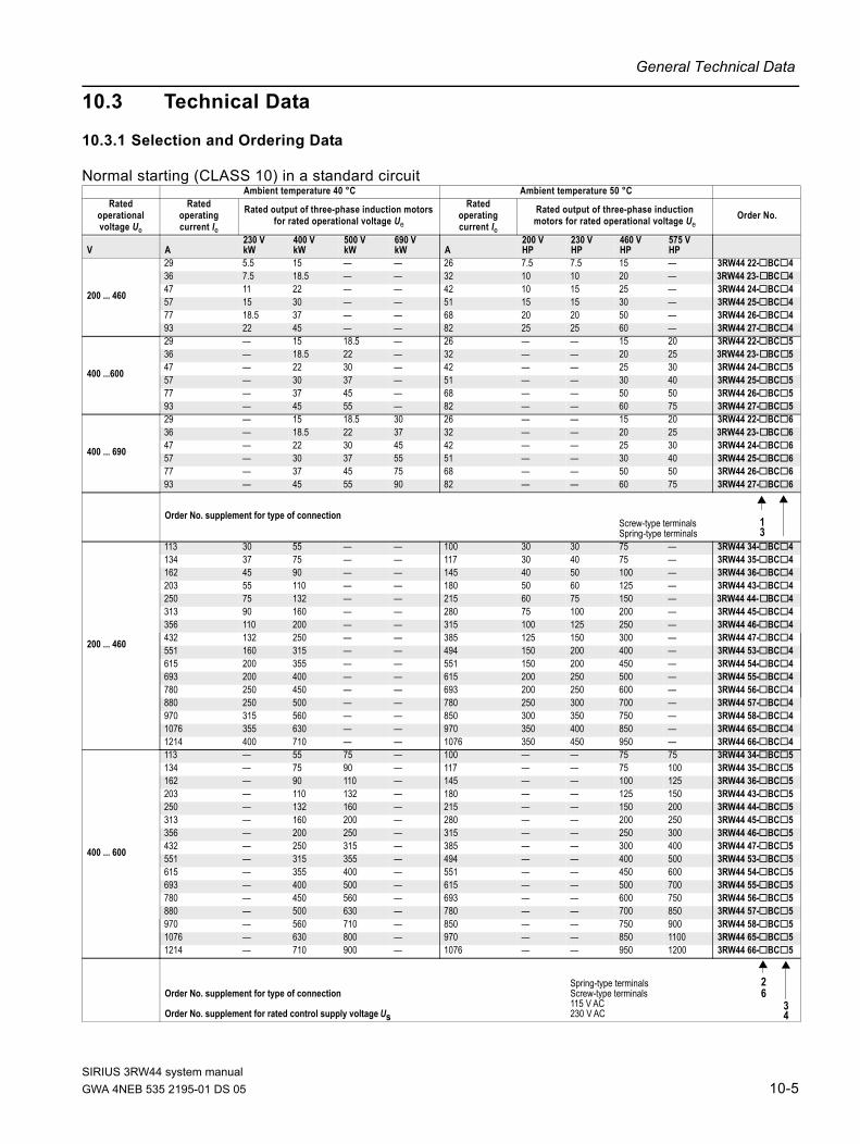
General Technical Data
SIRIUS 3RW44 system manual
10.3 Technical Data
10.3.1 Selection and Ordering Data
Normal starting (CLASS 10) in a standard circuitAmbient temperature 40 °C Ambient temperature 50 °C
Rated operational voltage Ue
Rated operating current Ie
Rated output of three-phase induction motors for rated operational voltage Ue
Rated operating current Ie
Rated output of three-phase induction motors for rated operational voltage Ue
Order No.
V A230 V kW
400 V kW
500 V kW
690 V kW A
200 V HP
230 V HP
460 V HP
575 V HP
200 ... 460
29 5.5 15 — — 26 7.5 7.5 15 — 3RW44 22-@BC@436 7.5 18.5 — — 32 10 10 20 — 3RW44 23-@BC@447 11 22 — — 42 10 15 25 — 3RW44 24-@BC@457 15 30 — — 51 15 15 30 — 3RW44 25-@BC@477 18.5 37 — — 68 20 20 50 — 3RW44 26-@BC@493 22 45 — — 82 25 25 60 — 3RW44 27-@BC@4
400 ...600
29 — 15 18.5 — 26 — — 15 20 3RW44 22-@BC@536 — 18.5 22 — 32 — — 20 25 3RW44 23-@BC@547 — 22 30 — 42 — — 25 30 3RW44 24-@BC@557 — 30 37 — 51 — — 30 40 3RW44 25-@BC@577 — 37 45 — 68 — — 50 50 3RW44 26-@BC@593 — 45 55 — 82 — — 60 75 3RW44 27-@BC@5
400 ... 690
29 — 15 18.5 30 26 — — 15 20 3RW44 22-@BC@636 — 18.5 22 37 32 — — 20 25 3RW44 23-@BC@647 — 22 30 45 42 — — 25 30 3RW44 24-@BC@657 — 30 37 55 51 — — 30 40 3RW44 25-@BC@677 — 37 45 75 68 — — 50 50 3RW44 26-@BC@693 — 45 55 90 82 — — 60 75 3RW44 27-@BC@6
Order No. supplement for type of connectionScrew-type terminalsSpring-type terminals
200 ... 460
113 30 55 — — 100 30 30 75 — 3RW44 34-@BC@4134 37 75 — — 117 30 40 75 — 3RW44 35-@BC@4162 45 90 — — 145 40 50 100 — 3RW44 36-@BC@4203 55 110 — — 180 50 60 125 — 3RW44 43-@BC@4250 75 132 — — 215 60 75 150 — 3RW44 44-@BC@4313 90 160 — — 280 75 100 200 — 3RW44 45-@BC@4356 110 200 — — 315 100 125 250 — 3RW44 46-@BC@4432 132 250 — — 385 125 150 300 — 3RW44 47-@BC@4551 160 315 — — 494 150 200 400 — 3RW44 53-@BC@4615 200 355 — — 551 150 200 450 — 3RW44 54-@BC@4693 200 400 — — 615 200 250 500 — 3RW44 55-@BC@4780 250 450 — — 693 200 250 600 — 3RW44 56-@BC@4880 250 500 — — 780 250 300 700 — 3RW44 57-@BC@4970 315 560 — — 850 300 350 750 — 3RW44 58-@BC@41076 355 630 — — 970 350 400 850 — 3RW44 65-@BC@41214 400 710 — — 1076 350 450 950 — 3RW44 66-@BC@4
400 ... 600
113 — 55 75 — 100 — — 75 75 3RW44 34-@BC@5134 — 75 90 — 117 — — 75 100 3RW44 35-@BC@5162 — 90 110 — 145 — — 100 125 3RW44 36-@BC@5203 — 110 132 — 180 — — 125 150 3RW44 43-@BC@5250 — 132 160 — 215 — — 150 200 3RW44 44-@BC@5313 — 160 200 — 280 — — 200 250 3RW44 45-@BC@5356 — 200 250 — 315 — — 250 300 3RW44 46-@BC@5432 — 250 315 — 385 — — 300 400 3RW44 47-@BC@5551 — 315 355 — 494 — — 400 500 3RW44 53-@BC@5615 — 355 400 — 551 — — 450 600 3RW44 54-@BC@5693 — 400 500 — 615 — — 500 700 3RW44 55-@BC@5780 — 450 560 — 693 — — 600 750 3RW44 56-@BC@5880 — 500 630 — 780 — — 700 850 3RW44 57-@BC@5970 — 560 710 — 850 — — 750 900 3RW44 58-@BC@51076 — 630 800 — 970 — — 850 1100 3RW44 65-@BC@51214 — 710 900 — 1076 — — 950 1200 3RW44 66-@BC@5
Order No. supplement for type of connection
Order No. supplement for rated control supply voltage Us
Spring-type terminalsScrew-type terminals115 V AC230 V AC
13
26
34
GWA 4NEB 535 2195-01 DS 05 10-5

General Technical Data
400 ... 690
113 — 55 75 110 100 — — 75 75 3RW44 34-@BC@6134 — 75 90 132 117 — — 75 100 3RW44 35-@BC@6162 — 90 110 160 145 — — 100 125 3RW44 36-@BC@6203 — 110 132 200 180 — — 125 150 3RW44 43-@BC@6250 — 132 160 250 215 — — 150 200 3RW44 44-@BC@6313 — 160 200 315 280 — — 200 250 3RW44 45-@BC@6356 — 200 250 355 315 — — 250 300 3RW44 46-@BC@6432 — 250 315 400 385 — — 300 400 3RW44 47-@BC@6551 — 315 355 560 494 — — 400 500 3RW44 53-@BC@6615 — 355 400 630 551 — — 450 600 3RW44 54-@BC@6693 — 400 500 710 615 — — 500 700 3RW44 55-@BC@6780 — 450 560 800 693 — — 600 750 3RW44 56-@BC@6880 — 500 630 900 780 — — 700 850 3RW44 57-@BC@6970 — 560 710 1000 850 — — 750 900 3RW44 58-@BC@61076 — 630 800 1100 970 — — 850 1100 3RW44 65-@BC@61214 — 710 900 1200 1076 — — 950 1200 3RW44 66-@BC@6
Order No. supplement for type of connection
Order No. supplement for rated control supply voltage Us
Spring-type terminalsScrew-type terminals115 V AC230 V AC
Ambient temperature 40 °C Ambient temperature 50 °CRated
operational voltage Ue
Rated operating current Ie
Rated output of three-phase induction motors for rated operational voltage Ue
Rated operating current Ie
Rated output of three-phase induction motors for rated operational voltage Ue
Order No.
26
34
SIRIUS 3RW44 system manual10-6 GWA 4NEB 535 2195-01 DS 05

General Technical Data
SIRIUS 3RW44 system manual
Heavy starting (CLASS 20) in a standard circuitAmbient temperature 40 °C Ambient temperature 50 °C
Ratedoperational voltage Ue
Ratedoperating current Ie
Rated output of three-phase induction motors for rated operational voltage Ue
Ratedoperating current Ie
Rated output of three-phase induction motors for rated operational voltage Ue
Order No.
V A230 V kW
400 V kW
500 V kW
690 V kW A
200 V HP
230 V HP
460 V HP
575 V HP
200 ... 460
29 5.5 15 — — 26 7.5 7.5 15 — 3RW44 22-@BC@436 7.5 18.5 — — 32 10 10 20 — 3RW44 23-@BC@447 11 22 — — 42 10 15 25 — 3RW44 24-@BC@457 15 30 — — 51 15 15 30 — 3RW44 25-@BC@477 18.5 37 — — 68 20 20 50 — 3RW44 27-@BC@4
400 ...600
29 — 15 18.5 — 26 — — 15 20 3RW44 22-@BC@536 — 18.5 22 — 32 — — 20 25 3RW44 23-@BC@547 — 22 30 — 42 — — 25 30 3RW44 24-@BC@557 — 30 37 — 51 — — 30 40 3RW44 25-@BC@577 — 37 45 — 68 — — 50 50 3RW44 27-@BC@5
400 ... 690
29 — 15 18.5 30 26 — — 15 20 3RW44 22-@BC@636 — 18.5 22 37 32 — — 20 25 3RW44 23-@BC@647 — 22 30 45 42 — — 25 30 3RW44 24-@BC@657 — 30 37 55 51 — — 30 40 3RW44 25-@BC@677 — 37 45 75 68 — — 50 50 3RW44 27-@BC@6
Order No. supplement for type of connection Screw-type terminalsSpring-type terminals
200 ... 460
93 22 45 — — 82 25 25 60 — 3RW44 34-@BC@4113 30 55 — — 100 30 30 75 — 3RW44 35-@BC@4134 37 75 — — 117 30 40 75 — 3RW44 36-@BC@4162 45 90 — — 145 40 50 100 — 3RW44 43-@BC@4203 55 110 — — 180 50 60 125 — 3RW44 45-@BC@4250 75 132 — — 215 60 75 150 — 3RW44 46-@BC@4313 90 160 — — 280 75 100 200 — 3RW44 47-@BC@4356 110 200 — — 315 100 125 250 — 3RW44 47-@BC@4432 132 250 — — 385 125 150 300 — 3RW44 53-@BC@4551 160 315 — — 494 150 200 400 — 3RW44 53-@BC@4615 200 355 — — 551 150 200 450 — 3RW44 55-@BC@4693 200 400 — — 615 200 250 500 — 3RW44 57-@BC@4780 250 450 — — 693 200 250 600 — 3RW44 65-@BC@4880 250 500 — — 780 250 300 700 — 3RW44 65-@BC@4970 315 560 — — 850 300 350 750 — 3RW44 65-@BC@4
400 ... 600
93 — 45 55 — 82 — — 60 75 3RW44 34-@BC@5113 — 55 75 — 100 — — 75 75 3RW44 35-@BC@5134 — 75 90 — 117 — — 75 100 3RW44 36-@BC@5162 — 90 110 — 145 — — 100 125 3RW44 43-@BC@5203 — 110 132 — 180 — — 125 150 3RW44 45-@BC@5250 — 132 160 — 215 — — 150 200 3RW44 46-@BC@5313 — 160 200 — 280 — — 200 250 3RW44 47-@BC@5356 — 200 250 — 315 — — 250 300 3RW44 47-@BC@5432 — 250 315 — 385 — — 300 400 3RW44 53-@BC@5551 — 315 355 — 494 — — 400 500 3RW44 53-@BC@5615 — 355 400 — 551 — — 450 600 3RW44 54-@BC@5693 — 400 500 — 615 — — 500 700 3RW44 57-@BC@5780 — 450 560 — 693 — — 600 750 3RW44 55-@BC@5880 — 500 630 — 780 — — 700 850 3RW44 65-@BC@5970 — 560 710 — 850 — — 750 950 3RW44 65-@BC@5
400 ... 690
93 — 45 55 90 82 — — 60 75 3RW44 34-@BC@6113 — 55 75 110 100 — — 75 75 3RW44 35-@BC@6134 — 75 90 132 117 — — 75 100 3RW44 36-@BC@6162 — 90 110 160 145 — — 100 125 3RW44 43-@BC@6203 — 110 132 200 180 — — 125 150 3RW44 45-@BC@6250 — 132 160 250 215 — — 150 200 3RW44 46-@BC@6313 — 160 200 315 280 — — 200 250 3RW44 47-@BC@6356 — 200 250 355 315 — — 250 300 3RW44 47-@BC@6432 — 250 315 400 385 — — 300 400 3RW44 53-@BC@6551 — 315 355 560 494 — — 400 500 3RW44 53-@BC@6615 — 355 400 630 551 — — 450 600 3RW44 55-@BC@6693 — 400 500 710 615 — — 500 700 3RW44 57-@BC@6780 — 450 560 800 693 — — 600 750 3RW44 65-@BC@6880 — 500 630 900 780 — — 700 850 3RW44 65-@BC@6970 — 560 710 1000 850 — — 750 950 3RW44 65-@BC@6
Order No. supplement for type of connection
Order No. supplement for rated control supply voltage Us
Spring-type terminalsScrew-type terminals115 V AC230 V AC
13
26
34
GWA 4NEB 535 2195-01 DS 05 10-7
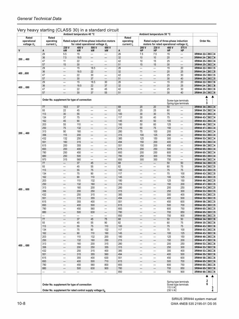
General Technical Data
Very heavy starting (CLASS 30) in a standard circuitAmbient temperature 40 °C Ambient temperature 50 °C
Ratedoperational voltage Ue
Ratedoperating current Ie
Rated output of three-phase induction motors for rated operational voltage Ue
Ratedoperating current Ie
Rated output of three-phase induction motors for rated operational voltage Ue
Order No.
V A230 V kW
400 V kW
500 V kW
690 V kW A
200 V HP
230 V HP
460 V HP
575 V HP
200 ... 460
29 5.5 15 — — 26 7.5 7.5 15 — 3RW44 22-@BC@436 7.5 18.5 — — 32 10 10 20 — 3RW44 24-@BC@447 11 22 — — 42 10 15 25 — 3RW44 25-@BC@457 15 30 — — 51 15 15 30 — 3RW44 25-@BC@4
400 ...600
29 — 15 18.5 — 26 — — 15 20 3RW44 22-@BC@536 — 18.5 22 — 32 — — 20 25 3RW44 24-@BC@547 — 22 30 — 42 — — 25 30 3RW44 25-@BC@557 — 30 37 — 51 — — 30 40 3RW44 25-@BC@5
400 ... 690
29 — 15 18.5 30 26 — — 15 20 3RW44 22-@BC@636 — 18.5 22 37 32 — — 20 25 3RW44 24-@BC@647 — 22 30 45 42 — — 25 30 3RW44 25-@BC@657 — 30 37 55 51 — — 30 40 3RW44 25-@BC@6
Order No. supplement for type of connection Screw-type terminalsSpring-type terminals
200 ... 460
77 18,5 37 — — 68 20 20 50 — 3RW44 34-@BC@493 22 45 — — 82 25 25 60 — 3RW44 35-@BC@4113 30 55 — — 100 30 30 75 — 3RW44 43-@BC@4134 37 75 — — 117 30 40 75 — 3RW44 43-@BC@4162 45 90 — — 145 40 50 100 — 3RW44 43-@BC@4203 55 110 — — 180 50 60 125 — 3RW44 46-@BC@4250 75 132 — — 215 60 75 150 — 3RW44 47-@BC@4313 90 160 — — 280 75 100 200 — 3RW44 53-@BC@4356 110 200 — — 315 100 125 250 — 3RW44 53-@BC@4432 132 250 — — 385 125 150 300 — 3RW44 53-@BC@4551 160 315 — — 494 150 200 400 — 3RW44 55-@BC@4615 200 355 — — 551 150 200 450 — 3RW44 58-@BC@4693 200 400 — — 615 200 250 500 — 3RW44 65-@BC@4780 250 450 — — 693 200 250 600 — 3RW44 65-@BC@4880 250 500 — — 780 250 300 700 — 3RW44 65-@BC@4970 315 560 — — 850 300 350 750 — 3RW44 66-@BC@4
400 ... 600
77 — 37 45 — 68 — — 50 50 3RW44 34-@BC@593 — 45 55 — 82 — — 60 75 3RW44 35-@BC@5113 — 55 75 — 100 — — 75 75 3RW44 43-@BC@5134 — 75 90 — 117 — — 75 100 3RW44 43-@BC@5162 — 90 110 — 145 — — 100 125 3RW44 43-@BC@5203 — 110 132 — 180 — — 125 150 3RW44 46-@BC@5250 — 132 160 — 215 — — 150 200 3RW44 47-@BC@5313 — 160 200 — 280 — — 200 250 3RW44 53-@BC@5356 — 200 250 — 315 — — 250 300 3RW44 53-@BC@5432 — 250 315 — 385 — — 300 400 3RW44 53-@BC@5551 — 315 355 — 494 — — 400 500 3RW44 55-@BC@5615 — 355 400 — 551 — — 450 600 3RW44 58-@BC@5693 — 400 500 — 615 — — 500 700 3RW44 65-@BC@5780 — 450 560 — 693 — — 600 750 3RW44 65-@BC@5880 — 500 630 — 780 — — 700 850 3RW44 65-@BC@5— — — — — 850 — — 750 900 3RW44 66-@BC@5
400 ... 690
77 — 37 45 75 68 — — 50 50 3RW44 34-@BC@693 — 45 55 90 82 — — 60 75 3RW44 35-@BC@6113 — 55 75 110 100 — — 75 75 3RW44 43-@BC@6134 — 75 90 132 117 — — 75 100 3RW44 43-@BC@6162 — 90 110 160 145 — — 100 125 3RW44 43-@BC@6203 — 110 132 200 180 — — 125 150 3RW44 46-@BC@6250 — 132 160 250 215 — — 150 200 3RW44 47-@BC@6313 — 160 200 315 280 — — 200 250 3RW44 53-@BC@6356 — 200 250 355 315 — — 250 300 3RW44 53-@BC@6432 — 250 315 400 385 — — 300 400 3RW44 53-@BC@6551 — 315 355 560 494 — — 400 500 3RW44 55-@BC@6615 — 355 400 630 551 — — 450 600 3RW44 58-@BC@6693 — 400 500 710 615 — — 500 700 3RW44 65-@BC@6780 — 450 560 800 693 — — 600 750 3RW44 65-@BC@6880 — 500 630 900 780 — — 700 850 3RW44 65-@BC@6— — — — — 850 — — 750 900 3RW44 66-@BC@6
Order No. supplement for type of connection
Order No. supplement for rated control supply voltage Us
Spring-type terminalsScrew-type terminals115 V AC230 V AC
13
26
34
SIRIUS 3RW44 system manual10-8 GWA 4NEB 535 2195-01 DS 05
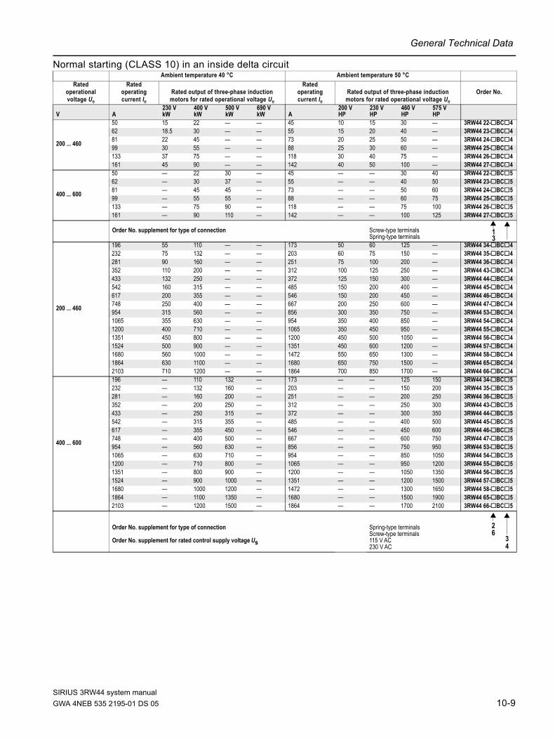
General Technical Data
SIRIUS 3RW44 system manual
Normal starting (CLASS 10) in an inside delta circuitAmbient temperature 40 °C Ambient temperature 50 °C
Ratedoperational voltage Ue
Ratedoperating current Ie
Rated output of three-phase induction motors for rated operational voltage Ue
Ratedoperating current Ie
Rated output of three-phase induction motors for rated operational voltage Ue
Order No.
V A230 V kW
400 V kW
500 V kW
690 V kW A
200 V HP
230 V HP
460 V HP
575 V HP
200 ... 460
50 15 22 — — 45 10 15 30 — 3RW44 22-@BC@462 18.5 30 — — 55 15 20 40 — 3RW44 23-@BC@481 22 45 — — 73 20 25 50 — 3RW44 24-@BC@499 30 55 — — 88 25 30 60 — 3RW44 25-@BC@4133 37 75 — — 118 30 40 75 — 3RW44 26-@BC@4161 45 90 — — 142 40 50 100 — 3RW44 27-@BC@4
400 ... 600
50 — 22 30 — 45 — — 30 40 3RW44 22-@BC@562 — 30 37 — 55 — — 40 50 3RW44 23-@BC@581 — 45 45 — 73 — — 50 60 3RW44 24-@BC@599 — 55 55 — 88 — — 60 75 3RW44 25-@BC@5133 — 75 90 — 118 — — 75 100 3RW44 26-@BC@5161 — 90 110 — 142 — — 100 125 3RW44 27-@BC@5
Order No. supplement for type of connection Screw-type terminalsSpring-type terminals
200 ... 460
196 55 110 — — 173 50 60 125 — 3RW44 34-@BC@4232 75 132 — — 203 60 75 150 — 3RW44 35-@BC@4281 90 160 — — 251 75 100 200 — 3RW44 36-@BC@4352 110 200 — — 312 100 125 250 — 3RW44 43-@BC@4433 132 250 — — 372 125 150 300 — 3RW44 44-@BC@4542 160 315 — — 485 150 200 400 — 3RW44 45-@BC@4617 200 355 — — 546 150 200 450 — 3RW44 46-@BC@4748 250 400 — — 667 200 250 600 — 3RW44 47-@BC@4954 315 560 — — 856 300 350 750 — 3RW44 53-@BC@41065 355 630 — — 954 350 400 850 — 3RW44 54-@BC@41200 400 710 — — 1065 350 450 950 — 3RW44 55-@BC@41351 450 800 — — 1200 450 500 1050 — 3RW44 56-@BC@41524 500 900 — — 1351 450 600 1200 — 3RW44 57-@BC@41680 560 1000 — — 1472 550 650 1300 — 3RW44 58-@BC@41864 630 1100 — — 1680 650 750 1500 — 3RW44 65-@BC@42103 710 1200 — — 1864 700 850 1700 — 3RW44 66-@BC@4
400 ... 600
196 — 110 132 — 173 — — 125 150 3RW44 34-@BC@5232 — 132 160 — 203 — — 150 200 3RW44 35-@BC@5281 — 160 200 — 251 — — 200 250 3RW44 36-@BC@5352 — 200 250 — 312 — — 250 300 3RW44 43-@BC@5433 — 250 315 — 372 — — 300 350 3RW44 44-@BC@5542 — 315 355 — 485 — — 400 500 3RW44 45-@BC@5617 — 355 450 — 546 — — 450 600 3RW44 46-@BC@5748 — 400 500 — 667 — — 600 750 3RW44 47-@BC@5954 — 560 630 — 856 — — 750 950 3RW44 53-@BC@51065 — 630 710 — 954 — — 850 1050 3RW44 54-@BC@51200 — 710 800 — 1065 — — 950 1200 3RW44 55-@BC@51351 — 800 900 — 1200 — — 1050 1350 3RW44 56-@BC@51524 — 900 1000 — 1351 — — 1200 1500 3RW44 57-@BC@51680 — 1000 1200 — 1472 — — 1300 1650 3RW44 58-@BC@51864 — 1100 1350 — 1680 — — 1500 1900 3RW44 65-@BC@52103 — 1200 1500 — 1864 — — 1700 2100 3RW44 66-@BC@5
Order No. supplement for type of connection
Order No. supplement for rated control supply voltage Us
Spring-type terminalsScrew-type terminals115 V AC230 V AC
13
26
34
GWA 4NEB 535 2195-01 DS 05 10-9
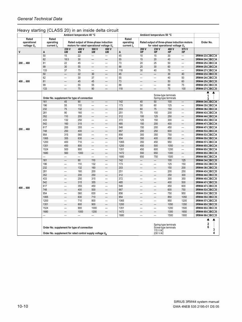
General Technical Data
Heavy starting (CLASS 20) in an inside delta circuitAmbient temperature 40 °C Ambient temperature 50 °C
Ratedoperational voltage Ue
Ratedoperating current Ie
Rated output of three-phase induction motors for rated operational voltage Ue
Ratedoperating current Ie
Rated output of three-phase induction motors for rated operational voltage Ue
Order No.
V A230 V kW
400 V kW
500 V kW
690 V kW A
200 V HP
230 V HP
460 V HP
575 V HP
200 ... 460
50 15 22 — — 45 10 15 30 — 3RW44 23-@BC@462 18.5 30 — — 55 15 20 40 — 3RW44 24-@BC@481 22 45 — — 73 20 25 50 — 3RW44 25-@BC@499 30 55 — — 88 25 30 60 — 3RW44 25-@BC@4133 37 75 — — 118 30 40 75 — 3RW44 27-@BC@4
400 ... 600
50 — 22 30 — 45 — — 30 40 3RW44 23-@BC@562 — 30 37 — 55 — — 40 50 3RW44 24-@BC@581 — 45 45 — 73 — — 50 60 3RW44 25-@BC@599 — 55 55 — 88 — — 60 75 3RW44 25-@BC@5133 — 75 90 — 118 — — 75 100 3RW44 27-@BC@5
Order No. supplement for type of connectionScrew-type terminalsSpring-type terminals
200 ... 460
161 45 90 — — 142 40 50 100 — 3RW44 34-@BC@4196 55 110 — — 173 50 60 125 — 3RW44 35-@BC@4232 75 132 — — 203 60 75 150 — 3RW44 36-@BC@4281 90 160 — — 251 75 100 200 — 3RW44 43-@BC@4352 110 200 — — 312 100 125 250 — 3RW44 44-@BC@4433 132 250 — — 372 125 150 300 — 3RW44 45-@BC@4542 160 315 — — 485 150 200 400 — 3RW44 47-@BC@4617 200 355 — — 546 150 200 450 — 3RW44 47-@BC@4748 250 400 — — 667 200 250 600 — 3RW44 53-@BC@4954 315 560 — — 856 300 350 750 — 3RW44 53-@BC@41065 355 630 — — 954 350 400 850 — 3RW44 55-@BC@41200 400 710 — — 1065 350 450 950 — 3RW44 57-@BC@41351 450 800 — — 1200 450 500 1050 — 3RW44 65-@BC@41524 500 900 — — 1351 450 600 1200 — 3RW44 65-@BC@41680 560 1000 — — 1472 550 650 1300 — 3RW44 65-@BC@4— — — — — 1680 650 750 1500 — 3RW44 66-@BC@4
400 ... 600
161 — 90 110 — 142 — — 100 125 3RW44 34-@BC@5196 — 110 132 — 173 — — 125 150 3RW44 35-@BC@5232 — 132 160 — 203 — — 150 200 3RW44 36-@BC@5281 — 160 200 — 251 — — 200 250 3RW44 43-@BC@5352 — 200 250 — 312 — — 250 300 3RW44 44-@BC@5433 — 250 315 — 372 — — 300 350 3RW44 45-@BC@5542 — 315 355 — 485 — — 400 500 3RW44 47-@BC@5617 — 355 450 — 546 — — 450 600 3RW44 47-@BC@5748 — 400 500 — 667 — — 600 750 3RW44 53-@BC@5954 — 560 630 — 856 — — 750 950 3RW44 53-@BC@51065 — 630 710 — 954 — — 850 1050 3RW44 55-@BC@51200 — 710 800 — 1065 — — 950 1200 3RW44 57-@BC@51351 — 800 900 — 1200 — — 1050 1350 3RW44 65-@BC@51524 — 900 1000 — 1351 — — 1200 1500 3RW44 65-@BC@51680 — 1000 1200 — 1472 — — 1300 1650 3RW44 65-@BC@5— — — — — 1680 — — 1500 1900 3RW44 66-@BC@5
Order No. supplement for type of connection
Order No. supplement for rated control supply voltage Us
Spring-type terminalsScrew-type terminals115 V AC230 V AC
13
26
34
SIRIUS 3RW44 system manual10-10 GWA 4NEB 535 2195-01 DS 05

General Technical Data
SIRIUS 3RW44 system manual
Very heavy starting (CLASS 30) in an inside delta circuitAmbient temperature 40 °C Ambient temperature 50 °C
Ratedoperational voltage Ue
Ratedoperating current Ie
Rated output of three-phase induction motors for rated operational voltage Ue
Ratedoperating current Ie
Rated output of three-phase induction motors for rated operational voltage Ue
Order No.
V A230 V kW
400 V kW
500 V kW
690 V kW A
200 V HP
230 V HP
460 V HP
575 V HP
200 ... 460
50 15 22 — — 45 10 15 30 — 3RW44 23-@BC@462 18.5 30 — — 55 15 20 40 — 3RW44 24-@BC@481 22 45 — — 73 20 25 50 — 3RW44 25-@BC@499 30 55 — — 88 25 30 60 — 3RW44 25-@BC@4133 37 75 — — 118 30 40 75 — 3RW44 27-@BC@4
400 ... 600
50 — 22 30 — 45 — — 30 40 3RW44 23-@BC@562 — 30 37 — 55 — — 40 50 3RW44 24-@BC@581 — 45 45 — 73 — — 50 60 3RW44 25-@BC@599 — 55 55 — 88 — — 60 75 3RW44 25-@BC@5133 — 75 90 — 118 — — 75 100 3RW44 27-@BC@5
Order No. supplement for type of connection Screw-type terminalsSpring-type terminals
200 ... 460
161 45 90 — — 142 40 50 100 — 3RW44 35-@BC@4196 55 110 — — 173 50 60 125 — 3RW44 36-@BC@4232 75 132 — — 203 60 75 150 — 3RW44 43-@BC@4281 90 160 — — 251 75 100 200 — 3RW44 43-@BC@4352 110 200 — — 312 100 125 250 — 3RW44 45-@BC@4433 132 250 — — 372 125 150 300 — 3RW44 47-@BC@4542 160 315 — — 485 150 200 400 — 3RW44 53-@BC@4617 200 355 — — 546 150 200 450 — 3RW44 53-@BC@4748 250 400 — — 667 200 250 600 — 3RW44 53-@BC@4954 315 560 — — 856 300 350 750 — 3RW44 55-@BC@41065 355 630 — — 954 350 400 850 — 3RW44 58-@BC@41200 400 710 — — 1065 350 450 950 — 3RW44 65-@BC@41351 450 800 — — 1200 450 500 1050 — 3RW44 65-@BC@41524 500 900 — — 1351 450 600 1200 — 3RW44 65-@BC@4— — — — — 1472 550 650 1300 — 3RW44 66-@BC@4
400 ... 600
161 — 90 110 — 142 — — 100 125 3RW44 35-@BC@5196 — 110 132 — 173 — — 125 150 3RW44 36-@BC@5232 — 132 160 — 203 — — 150 200 3RW44 43-@BC@5281 — 160 200 — 251 — — 200 250 3RW44 43-@BC@5352 — 200 250 — 312 — — 250 300 3RW44 45-@BC@5433 — 250 315 — 372 — — 300 350 3RW44 47-@BC@5542 — 315 355 — 485 — — 400 500 3RW44 53-@BC@5617 — 355 450 — 546 — — 450 600 3RW44 53-@BC@5748 — 400 500 — 667 — — 600 750 3RW44 53-@BC@5954 — 560 630 — 856 — — 750 950 3RW44 55-@BC@51065 — 630 710 — 954 — — 850 1050 3RW44 58-@BC@51200 — 710 800 — 1065 — — 950 1200 3RW44 65-@BC@51351 — 800 900 — 1200 — — 1050 1350 3RW44 65-@BC@51524 — 900 1000 — 1351 — — 1200 1500 3RW44 65-@BC@5— — — — — 1472 — — 1300 1650 3RW44 66-@BC@5
Order No. supplement for type of connection
Order No. supplement for rated control supply voltage Us
Spring-type terminalsScrew-type terminals115 V AC230 V AC
Marginal conditionsCLASS 10 (normal starting): CLASS 20 (heavy starting): CLASS 30 (very heavy starting):
Maximum starting time: 10 s 40 s 60 sCurrent limiting 300 % Set to 350 % Set to 350 %Starts/hour 5 max. 1 max. 1
13
26
34
General marginal conditionsOn-time motor 30%Stand-alone installationInstallation altitude max. 1,000 m / 3,280 ftAmbient temperature kW: 40 °C / 1,104 °F hp: 50 °C / 122 °FThe motor outputs listed are only rough values. The dimensioning of the soft starter should always be carried out on the basis of the motor current (rated operating current). A model with a higher output may be necessary for deviating conditions.
The motor output specifications are based on DIN 42973 (kW) and NEC 96/UL508 (hp).
For optimum dimensioning and/or deviations from the boundary conditions described, we recommend the use of the "Win Soft Starter" selection and simulation program, which can be downloaded at: http://www.siemens.com/softstarter >Software
GWA 4NEB 535 2195-01 DS 05 10-11

General Technical Data
10.3.2 Technical Data Power Unit
1) Measurement at 60 °C not required according to UL/CSA.2) Current limiting on soft starter set at 350 % IM; on-time OT = 70 %.3) During intermittent duty S4 with on-time OT = 70 %, Tu = 40 / 50 / 60 °C, vertical stand-alone installation. The listed switching frequencies do not apply to automatic operation.4) Maximum selectable rated motor current IM, depending on the CLASS settings.
Type 3RW44 ..-.BC.4 3RW44 ..-.BC.5 3RW44 ..-.BC.6Power electronicsRated operational voltage for standard circuit V 200 ... 460 AC 400 ... 600 AC 400 ... 690 ACTolerance % -15 / +10 -15 / +10 -15 / +10Rated operational voltage for inside delta circuit V 200 ... 460 AC 400 ... 600 AC 400 ... 600 ACTolerance % -15 / +10 -15 / +10 -15 / +10Maximum blocking voltage thyristor V 1400 1800 1800Rated frequency Hz 50 ... 60Tolerance % ±10 Continuous operation at 40 °C (% of Is) % 115Minimum load (% of set motor current IM) % 8Maximum cable length between soft starter and motor m 500 a)
a) During configuration, the voltage drop on the motor line must be taken into consideration up to the motor connection. It may be necessary to select a larger dimensioned soft starter with regard to the rated operational voltage and/or the rated operating current.
Permissible installation height m 5000 (for derating above 1000, see characteristic curves); higher on requestPermissible mounting positionand installation type (stand-alone installation)
Permissible ambient temperatureOperation °C 0 ... +60; (derating above +40)Storage °C -25 ... +80Degree of protection IP00
Type 3RW44 22 3RW44 23 3RW44 24 3RW44 25 3RW44 26 3RW44 27Power electronicsRated operating current Ie 29 36 47 57 77 93Carrying capacity, rated operating current Ie• According to IEC and UL / CSA 1), for single mounting, AC-53a
- At 40 / 50 / 60 °C A 29 / 26 /23 36 /32 / 29 47 /42 / 37 57 / 51 / 45 77 / 68 / 59 93 / 82 / 72Minimum selectable nominal motor current IM for motor overload protection A 5 7 9 11 15 18Power loss• Uninterrupted rated operating current after run up (40 / 50 / 60 °C) approx. W 8 / 7.5 / 7 10 / 9 / 8.5 32 / 31 / 29 36 / 34 / 31 45 / 41 / 37 55 / 51 / 47• When starting with current limiting set at 350 % IM (40 / 50 / 60 °C) W 400 / 345 / 290 470 / 410 / 355 600 / 515 / 440 725 / 630 / 525 940 / 790 / 660 1160 / 980 / 830Permitted rated motor current and starts per hour• For normal starting (CLASS 5)
- Rated motor current IM2), run-up time 5 s A 29 / 26 / 23 36 / 32.5 / 29 47 / 42 / 37 57 / 51 / 45 77 / 68 / 59 93 / 82 / 72- Starts per hour3) 1/h 41 34 41 41 41 41- Rated motor current IM2) 4), run-up time 10 s A 29 / 26 / 23 36 / 32.5 / 29 47 / 42 / 37 57 / 51 / 45 77 / 68 / 59 93 / 82 / 72- Starts per hour3) 1/h 20 15 20 20 20 20
• For normal starting (CLASS 10)- Rated motor current IM2), run-up time 10 s A 29 / 26 / 23 36 / 32.5 / 29 47 / 42 / 37 57 / 51 / 45 77 / 68 / 59 93 / 82 / 72- Starts per hour3) 1/h 20 15 20 20 20 20- Rated motor current IM2) 4), run-up time 20 s A 29 / 26 / 23 36 / 32.5 / 29 47 / 42 / 37 57 / 51 / 45 77 / 68 / 59 93 / 82 / 72- Starts per hour3) 1/h 10 6 10 10 8 8
• For normal starting (CLASS 15)- Rated motor current IM2), run-up time 15 s A 29 / 26 / 23 36 / 32.5 / 29 47 / 42 / 37 57 / 51 / 45 77 / 68 / 59 93 / 82 / 72- Starts per hour3) 1/h 13 9 13 13 13 13- Rated motor current IM2) 4), run-up time 30 s A 29 / 26 / 23 36 / 32.5 / 29 47 / 42 / 37 57 / 51 / 45 77 / 68 / 59 93 / 82 / 72- Starts per hour3) 1/h 6 4 6 6 6 6
• For heavy starting (CLASS 20)- Rated motor current IM2), run-up time 20 s A 29 / 26 / 23 36 / 32.5 / 29 47 / 42 / 37 57 / 51 / 45 77 / 68 / 59 88 / 80 / 72- Starts per hour3) 1/h 10 6 10 10 10 10- Rated motor current IM2) 4), run-up time 40 s A 29 / 26 / 23 36 / 32.5 / 29 47 / 42 / 37 57 / 51 / 45 77 / 68 / 59 88 / 80 / 72- Starts per hour3) 1/h 4 2 4 5 1.8 0.8
• For very heavy starting (CLASS 30)- Rated motor current IM2), run-up time 30 s A 29 / 26 / 23 36 / 32.5 / 29 47 / 42 / 37 57 / 51 / 45 65 / 60 / 54 77 / 70 / 63- Starts per hour3) 1/h 6 4 6 6 6 6- Rated motor current IM2) 4), run-up time 60 s A 29 / 26 / 23 36 / 32.5 / 29 47 / 42 / 37 57 / 51 / 45 65 / 60 / 54 77 / 70 / 63- Starts per hour3) 1/h 1.8 0.8 3.3 1.5 2 1
��������� � � � �
� � ≥ 5 mm (≥ 0.2 in)≥ 75 mm (≥ 3 in)≥ 100 mm (≥ 4 in)
SIRIUS 3RW44 system manual10-12 GWA 4NEB 535 2195-01 DS 05

General Technical Data
SIRIUS 3RW44 system manual
1) Measurement at 60 °C not required according to UL/CSA.2) Current limiting on soft starter set at 350 % IM; on-time OT = 70 %.3) During intermittent duty S4 with on-time OT = 70 %, Tu = 40/50/60 °C, vertical stand-alone installation. The listed switching frequencies do not apply to automatic operation.4) Maximum selectable rated motor current IM, depending on the CLASS settings.
Type 3RW44 34 3RW44 35 3RW44 36Power electronicsRated operating current Ie 113 134 162Carrying capacity, rated operating current Ie• According to IEC and UL / CSA 1), for single mounting, AC-53a
- At 40 °C A 113 134 162- At 50 °C A 100 117 145- At 60 °C A 88 100 125
Minimum selectable nominal motor current IM For motor overload protection A 22 26 32Power loss• Uninterrupted rated operating current after run up (40 / 50 / 60 °C) approx. W 64 / 58 / 53 76 / 67 / 58 95 / 83 / 71• When starting with current limiting set at 350 % IM (40 / 50 / 60 °C) W 1350 / 1140 / 970 1700 / 1400 / 1140 2460 / 1980 / 1620Permitted rated motor current and starts per hour• For normal starting (CLASS 5)
- Rated motor current IM2), run-up time 5 s A 113 / 100 / 88 134 / 117 / 100 162 / 145 / 125- Starts per hour3) 1/h 41 39 41- Rated motor current IM2) 4), run-up time 10 s A 113 / 100 / 88 134 / 117 / 100 162 / 145 / 125- Starts per hour3) 1/h 20 15 20
• For normal starting (CLASS 10)- Rated motor current IM2), run-up time 10 s A 113 / 100 / 88 134 / 117 / 100 162 / 145 / 125- Starts per hour3) 1/h 20 15 20- Rated motor current IM2) 4), run-up time 20 s A 113 / 100 / 88 134 / 117 / 100 162 / 145 / 125- Starts per hour3) 1/h 9 6 7
• For normal starting (CLASS 15)- Rated motor current IM2), run-up time 15 s A 113 / 100 / 88 134 / 117 / 100 162 / 145 / 125- Starts per hour3) 1/h 13 9 12- Rated motor current IM2) 4), run-up time 30 s A 113 / 100 / 88 134 / 117 / 100 162 / 145 / 125- Starts per hour3) 1/h 6 6 1
• For heavy starting (CLASS 20)- Rated motor current IM2), run-up time 20 s A 106 / 97 / 88 125 / 113 / 100 147 / 134 / 122- Starts per hour3) 1/h 9 9 10- Rated motor current IM2) 4), run-up time 40 s A 106 / 97 / 88 125 / 113 / 100 147 / 134 / 122- Starts per hour3) 1/h 1.5 2 1
• For very heavy starting (CLASS 30)- Rated motor current IM2), run-up time 30 s A 91 / 84 / 76 110 / 100 / 90 120 / 110 / 100- Starts per hour3) 1/h 6 6 6- Rated motor current IM2) 4), run-up time 60 s A 91 / 84 / 76 110 / 100 / 90 120 / 110 / 100- Starts per hour3) 1/h 2 2 2
GWA 4NEB 535 2195-01 DS 05 10-13
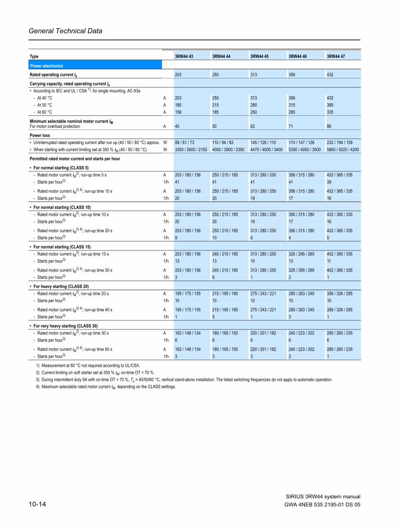
General Technical Data
1) Measurement at 60 °C not required according to UL/CSA.2) Current limiting on soft starter set at 350 % IM; on-time OT = 70 %.3) During intermittent duty S4 with on-time OT = 70 %, Tu = 40/50/60 °C, vertical stand-alone installation. The listed switching frequencies do not apply to automatic operation.4) Maximum selectable rated motor current IM, depending on the CLASS settings.
Type 3RW44 43 3RW44 44 3RW44 45 3RW44 46 3RW44 47
Power electronics
Rated operating current Ie 203 250 313 356 432
Carrying capacity, rated operating current Ie• According to IEC and UL / CSA 1), for single mounting, AC-53a
- At 40 °C A 203 250 313 356 432- At 50 °C A 180 215 280 315 385- At 60 °C A 156 185 250 280 335
Minimum selectable nominal motor current IM For motor overload protection A 40 50 62 71 86
Power loss• Uninterrupted rated operating current after run up (40 / 50 / 60 °C) approx. W 89 / 81 / 73 110 / 94 / 83 145 / 126 / 110 174 / 147 / 126 232 / 194 / 159• When starting with current limiting set at 350 % IM (40 / 50 / 60 °C) W 3350 / 2600 / 2150 4000 / 2900 / 2350 4470 / 4000 / 3400 5350 / 4050 / 3500 5860 / 5020 / 4200
Permitted rated motor current and starts per hour
• For normal starting (CLASS 5)- Rated motor current IM2), run-up time 5 s A 203 / 180 / 156 250 / 215 / 185 313 / 280 / 250 356 / 315 / 280 432 / 385 / 335- Starts per hour3) 1/h 41 41 41 41 39
- Rated motor current IM2) 4), run-up time 10 s A 203 / 180 / 156 250 / 215 / 185 313 / 280 / 250 356 / 315 / 280 432 / 385 / 335- Starts per hour3) 1/h 20 20 19 17 16
• For normal starting (CLASS 10)- Rated motor current IM2), run-up time 10 s A 203 / 180 / 156 250 / 215 / 185 313 / 280 / 250 356 / 315 / 280 432 / 385 / 335- Starts per hour3) 1/h 20 20 19 17 16
- Rated motor current IM2) 4), run-up time 20 s A 203 / 180 / 156 250 / 215 / 185 313 / 280 / 250 356 / 315 / 280 432 / 385 / 335- Starts per hour3) 1/h 9 10 6 4 5
• For normal starting (CLASS 15)- Rated motor current IM2), run-up time 15 s A 203 / 180 / 156 240 / 215 / 185 313 / 280 / 250 325 / 295 / 265 402 / 385 / 335- Starts per hour3) 1/h 13 13 10 13 11
- Rated motor current IM2) 4), run-up time 30 s A 203 / 180 / 156 240 / 215 / 185 313 / 280 / 250 325 / 295 / 265 402 / 385 / 335- Starts per hour3) 1/h 3 6 1 2 1
• For heavy starting (CLASS 20)- Rated motor current IM2), run-up time 20 s A 195 / 175 / 155 215 / 195 / 180 275 / 243 / 221 285 / 263 / 240 356 / 326 / 295- Starts per hour3) 1/h 10 10 10 10 10
- Rated motor current IM2) 4), run-up time 40 s A 195 / 175 / 155 215 / 195 / 180 275 / 243 / 221 285 / 263 / 240 356 / 326 / 295- Starts per hour3) 1/h 1 5 1 3 1
• For very heavy starting (CLASS 30)- Rated motor current IM2), run-up time 30 s A 162 / 148 / 134 180 / 165 / 150 220 / 201 / 182 240 / 223 / 202 285 / 260 / 235- Starts per hour3) 1/h 6 6 6 6 6
- Rated motor current IM2) 4), run-up time 60 s A 162 / 148 / 134 180 / 165 / 150 220 / 201 / 182 240 / 223 / 202 285 / 260 / 235- Starts per hour3) 1/h 3 3 3 2 1
SIRIUS 3RW44 system manual10-14 GWA 4NEB 535 2195-01 DS 05

General Technical Data
SIRIUS 3RW44 system manual
1) Measurement at 60 °C not required according to UL / CSA.2) Current limiting on soft starter set at 350 % IM; on-time OT = 70 %.3) During intermittent duty S4 with on-time OT = 70 %, Tu = 40 / 50 / 60 °C, vertical stand-alone installation. The listed switching frequencies do not apply to automatic operation.4) Maximum selectable rated motor current IM, depending on theCLASS settings.
Type 3RW44 53 3RW44 54 3RW44 55 3RW44 56 3RW44 57 3RW44 58 3RW44 65 3RW44 66Power electronicsCarrying capacity, rated operating current Ie• According to IEC and UL / CSA 1), for single mounting, AC-53a, at 40 °C A 551 615 693 780 880 970 1076 1214• According to IEC and UL / CSA 1), for single mounting, AC-53a, at 50 °C A 494 551 615 693 780 850 970 1076• According to IEC and UL / CSA 1), for single mounting, AC-53a, at 60 °C A 438 489 551 615 693 760 880 970Minimum selectable nominal motor current IM for motor overload protection A 110 123 138 156 176 194 215 242Power loss• Uninterrupted rated operating current after run up (40 °C) approx. W 159 186 220 214 250 270 510 630• Uninterrupted rated operating current after run up (50 °C) approx. W 135 156 181 176 204 215 420 510• Uninterrupted rated operating current after run up (60 °C) approx. W 113 130 152 146 168 179 360 420• When starting with current limiting set at 350 % IM (40 °C) W 7020 8100 9500 11100 13100 15000 15000 17500• When starting with current limiting set at 350 % IM (50 °C) W 6111 7020 8100 9500 11000 12500 13000 15000• When starting with current limiting set at 350 % IM (60 °C) W 5263 5996 7020 8100 8100 10700 11500 13000Permitted rated motor current and starts per hour• For normal starting (CLASS 5)
- Rated motor current IM2), run-up time 5 s, at 40 °C A 551 615 693 780 880 970 1076 1214- Rated motor current IM2), run-up time 5 s, at 50 °C A 494 551 615 693 780 850 970 1076- Rated motor current IM2), run-up time 5 s, at 60 °C A 438 489 551 615 693 760 880 970- Starts per hour3) 1/h 41 41 37 33 22 17 30 20- Rated motor current IM2) 4), run-up time 10 s, at 40 °C A 551 615 693 780 880 970 1076 1214- Rated motor current IM2) 4), run-up time 10 s, at 50 °C A 494 551 615 693 780 850 970 1076- Rated motor current IM2) 4), run-up time 10 s, at 60 °C A 438 489 551 615 693 760 880 970- Starts per hour3) 1/h 20 20 16 13 8 5 10 6
• For normal starting (CLASS 10)- Rated motor current IM2), run-up time 10 s, at 40 °C A 551 615 693 780 880 970 1076 1214- Rated motor current IM2), run-up time 10 s, at 50 °C A 494 551 615 693 780 850 970 1076- Rated motor current IM2), run-up time 10 s, at 60 °C A 438 489 551 615 693 760 880 970- Starts per hour3) 1/h 20 20 16 13 8 5 11 6- Rated motor current IM2) 4), run-up time 20 s, at 40 °C A 551 615 693 780 880 970 1076 1214- Rated motor current IM2) 4), run-up time 20 s, at 50 °C A 494 551 615 693 780 850 970 1076- Rated motor current IM2) 4), run-up time 20 s, at 60 °C A 438 489 551 615 693 760 880 970- Starts per hour3) 1/h 10 9 6 4 0.3 0.3 3 0.5
• For normal starting (CLASS 15)- Rated motor current IM2), run-up time 15 s, at 40 °C A 551 615 666 723 780 821 1020 1090- Rated motor current IM2), run-up time 15 s, at 50 °C A 494 551 615 693 710 755 950 1000- Rated motor current IM2), run-up time 15 s, at 60 °C A 438 489 551 615 650 693 850 920- Starts per hour3) 1/h 13 13 11 9 8 8 7 5- Rated motor current IM2) 4), run-up time 30 s, at 40 °C A 551 615 666 723 780 821 1020 1090- Rated motor current IM2) 4), run-up time 30 s, at 50 °C A 494 551 615 693 710 755 950 1000- Rated motor current IM2) 4), run-up time 30 s, at 60 °C A 438 489 551 615 650 693 850 920- Starts per hour3) 1/h 6 4 3 1 0.4 0.5 1 1
• For heavy starting (CLASS 20)- Rated motor current IM2), run-up time 20 s, at 40 °C A 551 591 633 670 710 740 970 1030- Rated motor current IM2), run-up time 20 s, at 50 °C A 494 551 615 634 650 685 880 940- Rated motor current IM2), run-up time 20 s, at 60 °C A 438 489 551 576 590 630 810 860- Starts per hour3) 1/h 10 10 7 8 8 9 7 5- Rated motor current IM2) 4), run-up time 40 s, at 40 °C A 551 591 633 670 710 740 970 1030- Rated motor current IM2) 4), run-up time 40 s, at 50 °C A 494 551 615 634 650 685 880 940- Rated motor current IM2) 4), run-up time 40 s, at 60 °C A 438 489 551 576 590 630 810 860- Starts per hour3) 1/h 4 2 1 1 0.4 1 1 1
• For very heavy starting (CLASS 30)- Rated motor current IM2), run-up time 30 s, at 40 °C A 500 525 551 575 600 630 880 920- Rated motor current IM2), run-up time 30 s, at 50 °C A 480 489 520 540 550 580 810 850- Rated motor current IM2), run-up time 30 s, at 60 °C A 438 455 480 490 500 530 740 780- Starts per hour3) 1/h 6 6 6 6 6 6 6 6- Rated motor current IM2) 4), run-up time 60 s, at 40 °C A 500 525 551 575 600 630 880 920- Rated motor current IM2) 4), run-up time 60 s, at 50 °C A 480 489 520 540 550 580 810 850- Rated motor current IM2) 4), run-up time 60 s, at 60 °C A 438 455 480 490 500 530 740 780- Starts per hour3) 1/h 2 1 1 1 1.5 1 1 1
GWA 4NEB 535 2195-01 DS 05 10-15

General Technical Data
10.3.3 Technical Data Control Unit
Type 3RW44 ..-.BC3. 3RW44 ..-.BC4.Terminal
Control unitRated valuesRated control supply voltage A1 / A2 / PE V 115 AC 230 AC• Tolerance % -15 / +10 -15 / +10Rated control supply current STANDBY mA 30 20Rated control supply current ON• 3RW44 2. mA 300 170• 3RW44 3. mA 500 250• 3RW44 4. mA 750 400• 3RW44 5. mA 450 200• 3RW44 6. mA 650 300Maximum current (pickup bypass)• 3RW44 2. mA 1000 500• 3RW44 3. mA 2500 1250• 3RW44 4. mA 6000 3000• 3RW44 5. mA 4500 2500• 3RW44 6. mA 4500 2500Rated frequency Hz 50 ... 60 50 ... 60• Tolerance % ±10 ±10
Type 3RW44 ..Control unit Terminal Factory settingControl inputsInput 1 IN1 Start motor right parameter set 1Input 2 IN2 No ActionInput 3 IN3 No ActionInput 4 IN4 Trip ResetSupply L+ / L-• Rated operating current mA Approx. 10 per input according to DIN 19240
• Rated operational voltage L+
Internal voltage: 24 V DC from internal supply via terminal L+ to IN1 ... IN4. Maximum load at L+ approx. 55 mA
L-
External voltage: DC externalvoltage (according to DIN 19240) via terminals L- and IN1 ... IN4 (min. 12 V DC, max. 30 V DC)
Thermistor motor protection inputInput T1/T2 PTC type A or Thermo click deactivatedRelay outputs (floating auxiliary contacts)Output 1 13/14 On-time motorOutput 2 23/24 No ActionOutput 3 33/34 No ActionOutput 4 95/96/98 Group errorSwitching capacity of the relay outputs230 V / AC-15 A 3 at 240 V24 V / DC-13 A 1 at 24 VOvervoltage protection Protection using varistor via relaycontact
Short-circuit protection4 A utilization category gL/gG; 6 A quick (fuse not included in scope of delivery)
Protective functionsMotor protection functionsTripping when motor is thermally overloadedTripping class according to IEC 60947-4-1 CLASS 5 / 10 / 15 / 20 / 30 10Phase loss sensitivity % >40Overload warning YesReset and recovery Manual / automatic ManualReset option after trip Manual / automatic ManualPre-charge time Min. 1 ... 30 1Device protection functionsTripping when thyristors thermally overloadedReset option after trip Manual / automatic ManualPre-charge time Min. 0.5Bypass protection functionsTripping when bypass contacts thermally overloadedReset option after trip ManualPre-charge time Min. 1
SIRIUS 3RW44 system manual10-16 GWA 4NEB 535 2195-01 DS 05

General Technical Data
SIRIUS 3RW44 system manual
Type 3RW44 .. Factory settingControl times and parametersControl timesSwitch-on delay (when control voltage applied) ms < 50Switch-on delay (automatic operation) ms < 4000Pre-charge time (ON command with active stopping mode) ms < 100Network failure bridging timeControl supply voltage ms 100Network failure reaction timeLoad circuit ms 100Reclosing lockout after overload tripMotor protection tripping Min. 1 ... 30 1Device protection tripping s 30Setting options for startingVoltage ramp start voltage % 20 ... 100 30Start torque control % 10 ... 100 10Limiting torque control % 20 ... 200 150Starting time s 0 ... 360 20Maximum starting time s 1 ... 1000 deactivatedCurrent limiting value % 125 ... 550 1) 450Breakaway voltage % 40 ... 100 80Breakaway time s 0 ... 2 deactivatedMotor thermal capacity % 1 ... 100 20Slow speed mode counter-clockwise / clockwiseSpeed factor in relation to nominal operating speed (n = nnominal/factor) 3 ... 21 7Slow speed torque 2) % 20 ... 100 50Setting options for stoppingStopping torque control % 10 ... 100 10Stopping time s 0 ... 360 10Dynamic braking torque % 20 ... 100 50DC braking torque % 20 ... 100 50Operating messages Checking voltage
Checking line phasesReady to startStart mode activeMotor runningStopping mode activeEmergency start active
Warnings / error messages No line voltagePhase angle control failurePhase loss• L1 / L2 / L3Missing load phase• T1 / T2 / T3Failure• Switching element 1 (thyristor) / switching element 2 (thyristor) / switching
Flash memory errorSupply voltage• below 75 %• below 85 %• above 110 %Current unbalance exceededThermal motor model overloadPrewarning limit exceeded• Motor heat build-up• Remaining time for trippingBypass element faultLine voltage too highDevice not identifiedVersions not matchingCurrent range exceededBypass element protective trippingOvercurrentMotor stalling – trippingCurrent limit exceededPower unit• Overheated• Overtemperature
1) max. current limiting value:
3RW44 22 - 3RW44 47:3RW44 53 - 3RW44 57:3RW44 58 - 3RW44 66:
550 %500 %450 %
2) Reference quantity depends on motor used, but in any case lower than the rated motor torque
GWA 4NEB 535 2195-01 DS 05 10-17

General Technical Data
1) Parameter motor left only possible in combination with slow speed.
Type 3RW44 .. Factory settingControl times and parametersWarnings / error messages (continued)
Temperature sensor• Overload• Wire breakage• Short-circuitGround fault• Detected• TrippingConnection break in manual operating modeMax. number of starts exceededIe limit value over / undershotCool-down time• Motor active• Contact block activeHeatsink thermistor• Wire breakage• Short-circuitQuick stop activeContact block defectiveImpermissible Ie / CLASS settingsNo external start parameters receivedPIO error
Control inputsInput 1 Motor right parameter set 1Input 2 No ActionInput 3 No ActionInput 4 Trip ResetParameterization options for control inputs 1 ... 4 No Action
Manual operation local operating modeEmergency startSlow speedQuick stopTrip ResetMotor right parameter set 1Motor left parameter set 1 1) Motor right parameter set 2Motor left parameter set 2 1) Motor right parameter set 3Motor left parameter set 3 1)
Relay outputsOutput 1 On-time motorOutput 2 No ActionOutput 3 No ActionOutput 4 Group errorParameterization options for relay inputs 1 ... 3 No Action
PIO Output 1PIO Output 2Input 1Input 2Input 3Input 4Run upBypass operationCoasting downOn-time motorCommand motor-onFansDC braking contactorGroup warningGroup errorBus errorDevice errorsPower onReady to start
Motor temperature sensor deactivated deactivatedThermo clickPTC type A
SIRIUS 3RW44 system manual10-18 GWA 4NEB 535 2195-01 DS 05

General Technical Data
SIRIUS 3RW44 system manual
10.3.4 Conductor Cross-Sections
1) When connecting cable lugs according to DIN 46235 from a conductor cross-section of 95 mm², the 3RT19 56-4EA1 terminal cover is required to ensure phase clearance.2) When connecting cable lugs according to DIN 46234 from a conductor cross-section of 240 mm² as well as DIN 46235 from a conductor cross-section of 185 mm², the 3RT19 66-4EA1
terminal cover is required to ensure phase clearance.
Type 3RW44 2. 3RW44 3. 3RW44 4. 3RW44 5. 3RW44 6.
Conductor cross-sectionsScrew-type terminals Main conductor:With box terminal 3RT19 55-4G (55 kW) 3RT19 66-4G —Front terminal connected
• Finely stranded with cable end sleeve mm2 2.5 ... 35 16 ... 70 70 ... 240 —• Finely stranded without cable end sleeve mm2 4 ... 50 16 ... 70 70 ... 240 —• Solid mm2 2.5 ... 16 — — —• Stranded mm2 4 ... 70 16 ... 70 95 ... 300 —• Ribbon cable (number x width x thickness) mm 6 x 9 x 0.8 min. 3 x 9 x 0.8,
max. 6 x 15.5 x 0.8min. 6 x 9 x 0.8max. 20 x 24 x 0.5
—
• AWG conductors, solid or stranded AWG 10 ... 2/0 6 ... 2/0 3/0 ... 600 kcmil —
Rear terminal connected • Finely stranded with cable end sleeve mm2 2.5 ... 50 16 ... 70 120 ... 185 —• Finely stranded without cable end sleeve mm2 10 ... 50 16 ... 70 120 ... 185 —• Solid mm2 2.5 ... 16 — — —• Stranded mm2 10 ... 70 16 ... 70 120 ... 240 —• Ribbon cable (number x width x thickness) mm 6 x 9 x 0.8 min. 3 x 9 x 0.8,
max. 6 x 15.5 x 0.8min. 6 x 9 x 0.8max. 20 x 24 x 0.5
—
• AWG conductors, solid or stranded AWG 10 ... 2/0 6 ... 2/0 250 ... 500 kcmil —
Both terminals connected
• Finely stranded with cable end sleeve mm2 2 x (2.5 ... 35) max. 1 x 50, 1 x 70 min. 2 x 50; max. 2 x 185
—
• Finely stranded without cable end sleeve mm2 2 x (4 ... 35) max. 1 x 50, 1 x 70 min. 2 x 50; max. 2 x 185
—
• Solid mm2 2 x (2.5 ... 16) — — —• Stranded mm2 2 x (4 ... 50) max. 2 x 70 max. 2 x 70;
max. 2 x 240—
• Ribbon cable (number x width x thickness) mm 2 x (6 x 9 x 0.8) max. 2 x(6 x 15.5 x 0.8)
max. 2 x(20 x 24 x 0.5)
—
• AWG conductors, solid or stranded AWG 2 x (10 ... 1/0) max. 2 x 1/0 min. 2 x 2/0; max. 2 x 500 kcmil
—
• Connecting screws M6 (hexagon socket, A/F4)
M10 (hexagon socket, A/F4)
M12 (hexagon socket, A/F5)
—
- Tightening torque Nm 4 ... 6 10 ... 12 20 ... 22 —lbf.in 36 ... 53 90 ... 110 180 ... 195 —
Screw-type terminals Main conductor:With box terminal — 3RT19 56-4G — —Front or rear terminal connected
• Finely stranded with cable end sleeve mm2 — 16 ... 120 — —• Finely stranded without cable end sleeve mm2 — 16 ... 120 — —• Stranded mm2 — 16 ... 120 — —• Ribbon cable (number x width x thickness) mm — min. 3 x 9 x 0.8
max. 6 x 15.5 x 0.8— —
• AWG conductors, solid or stranded AWG — 6 ... 250 kcmil — —
Both terminals connected
• Finely stranded with cable end sleeve mm2 — max. 1 x 95, 1 x 120 — —• Finely stranded without cable end sleeve mm2 — max. 1 x 95, 1 x 120 — —• Stranded mm2 — max. 2 x 120 — —• Ribbon cable (number x width x thickness) mm — max. 2 x
(10 x 15.5 x 0.8)— —
• AWG conductors, solid or stranded AWG — max. 2 x 3/0 — —
Screw-type terminals Main conductor:Without box terminal / busbar connections• Finely stranded with cable lug mm2 — 16 ... 951) 50 ... 2402) 50 ... 2402)
• Stranded with cable lug mm2 — 25 ... 1201) 70 ... 2402) 70 ... 2402)
• AWG conductors, solid or stranded AWG — 4 ... 250 kcmil 2/0 ... 500 kcmil 2/0 ... 500 kcmil• Connecting bar (max. width) mm — 17 25 60• Connecting screws — M8 x 25 (A/F13) M10 x 30 (A/F17) M12 x 40
- Tightening torque Nm — 10 ... 14 14 ... 24 20 ... 35lbf.in — 89 ... 124 124 ... 210 177 ... 310
��������
�������
������
��������
�������
������
GWA 4NEB 535 2195-01 DS 05 10-19

General Technical Data
10.3.5 Electromagnetic Compatibility
10.3.6 Utilization Classes
Regulation DIN EN 60947-4-1 (VDE 0660 Part 102), and/or IEC 60947-4-1 differentiate two utilization classes designated as "Utilization class 1" and "Utilization class 2". With both utilization classes, the short-circuit to be controlled is safely switched off. The only difference is the degree of damage to the device after a short-circuit.
Soft starters Type 3RW44 ..Conductor cross-sectionsAuxiliary conductor (1 or 2 conductors can be connected):
Screw-type terminals• Solid mm2 2 x (0.5 ... 2.5)• Finely stranded with cable end sleeve mm2 2 x (0.5 ... 1.5)• AWG conductors
- solid or stranded AWG 2 x (20 ... 14)- Finely stranded with cable end sleeve AWG 2 x (20 ... 16)
• Connecting screws- Tightening torque Nm 0.8 ... 1.2
lbf.in 7 ... 10.3Spring-type terminals• Solid mm2 2 x (0.25 ... 1.5)• Finely stranded with cable end sleeve mm2 2 x (0.25 ... 1.5)• AWG conductors, solid or stranded AWG 2 x (24 ... 16)
Standard ParameterElectromagnetic Compatibility according to EN 60947-4-2EMC interference immunity Electrostatic discharge (ESD) EN 61000-4-2 ±4 kV contact discharge, ±8 kV air dischargeElectromagnetic HF fields EN 61000-4-3 Frequency range: 80 ... 1000 MHz with 80 % at 1 kHz
Severity 3, 10 V/mConducted HF interference EN 61000-4-6 Frequency range: 150 kHz ... 80 MHz with 80 % at 1 kHz
Interference 10 VHF voltages and HF currents on conductors• Burst EN 61000-4-4 ±2 kV/5 kHz• Surge EN 61000-4-5 ±1 kV line to line
±2 kV line to groundEMC emission EMC radio interference field strength EN 55011 Limit value of Class A at 30 ... 1000 MHzRadio interference voltage EN 55011 Limit value of Class A at 0.15 ... 30 MHzIs a radio interference suppression filter required?Radio interference suppression A (industrial application) No
Utilization class 1 The fuseless load feeder can be inoperative after each short-circuit tripping. Damage to the contactor and the overload release is permissible. With 3RA1 load feeders, the circuit breaker itself always has utilization category 2.
Utilization class 2 After a short-circuit tripping, there must be no damage to the overload release or any other part. The 3RA1 fuseless load feeder can be restarted without any components needing to be replaced. Only welding of the contactor contacts is permissible, as long as they can be separated easily without any noticeable damage.
These utilization classes are highlighted in the Technical Data by an orange background.
1ToC
2ToC
SIRIUS 3RW44 system manual10-20 GWA 4NEB 535 2195-01 DS 05

General Technical Data
SIRIUS 3RW44 system manual
10.3.7 Branch Component Layout (Standard Circuit)
Fuse assignmentThe utilization class according to which the motor branch with soft starter is dimensioned depends on the requirements of the application. Normally, a fuseless design (combination of circuit breaker + soft starter) is sufficient. If the requirements for utilization class 2 must be met, semiconductor fuses must be used in the motor branch.
1) The rated motor current must be taken into consideration during device selection.2) For utilization class, see page 10-20.
Standard circuit fuseless design
Soft starters Circuit breaker1)
Nominal current 440 V +10 % Rated current
Q11 Q1Type A Type AUtilization class 12): 3RW44 22 ... 3RW44 27: Iq = 32 kA; 3RW44 34 and 3RW44 35: Iq = 16 kA; 3RW44 36 ... 3RW44 66: Iq = 65 kA3RW44 22 29 3RV10 42-4HA10 503RW44 23 36 3RV10 42-4JA10 633RW44 24 47 3RV10 42-4KA10 753RW44 25 57 3RV10 42-4LA10 903RW44 26 77 3RV10 42-4MA10 1003RW44 27 93 3RV10 42-4MA10 1003RW44 34 113 3VL17 16-2DD36 1603RW44 35 134 3VL17 16-2DD36 1603RW44 36 162 3VL37 25-2DC36 2503RW44 43 203 3VL47 31-3DC36 3153RW44 44 250 3VL47 31-3DC36 3153RW44 45 313 3VL47 40-3DC36 4003RW44 46 356 3VL47 40-3DC36 4003RW44 47 432 3VL57 50-3DC36 5003RW44 53 551 3VL67 80-3AB36 8003RW44 54 615 3VL67 80-3AB36 8003RW44 55 693 3VL67 80-3AB36 8003RW44 56 780 3VL77 10-3AB36 10003RW44 57 880 3VL77 10-3AB36 10003RW44 58 970 3VL77 12-3AB36 12503RW44 65 1076 3VL77 12-3AB36 12503RW44 66 1214 3VL77 12-3AB36 1250
Q11
NS
B0
_0
10
16
a
M3~
Q1
1ToC
GWA 4NEB 535 2195-01 DS 05 10-21

General Technical Data
1) If the "Combined braking" stopping function is selected, no braking contactor is required. If the "DC braking" function is selected, a braking contactor must be additionally used (for type, see table).The "DC braking" function is recommended for applications with larger centrifugal masses (Jload > Jmotor).
2) Additional K4 auxiliary relay: LZX:RT4A4T30 (3RW44 soft starter with 230 V AC rated control supply voltage), LZX:RT4A4S15 (3RW44 soft starter with 115 V AC rated control supply voltage).
3) "Utilization class 1" refers to the soft starter in combination with the protective device listed (circuit breaker/fuse), not to other components in the branch. For utilization class, see page 10-20.
Standard circuit fused design (line protection only)
Soft starters Line fuse, maximum Line contactor up to 400 V Braking contactor1)2)
Nominal current 690 V +5 % Rated current Size (option) (Circuit suggestions from page 9-2)
Q11 E1 Q21 Q91 Q92Type A Type A Type Type TypeUtilization class 13): Iq = 65 kA3RW44 22 29 3NA3 820-6 50 00 3RT10 34 3RT15 26 —3RW44 23 36 3NA3 822-6 63 00 3RT10 35 3RT15 26 —3RW44 24 47 3NA3 824-6 80 00 3RT10 36 3RT15 35 —3RW44 25 57 3NA3 830-6 100 00 3RT10 44 3RT15 35 —3RW44 26 77 3NA3 132-6 125 1 3RT10 45 3RT10 24 3RT10 353RW44 27 93 3NA3 136-6 160 1 3RT10 46 3RT10 25 3RT10 363RW44 34 113 3NA3 244-6 250 2 3RT10 54 3RT10 34 3RT10 443RW44 35 134 3NA3 244-6 250 2 3RT10 55 3RT10 36 3RT10 453RW44 36 162 3NA3 365-6 500 3 3RT10 56 3RT10 44 3RT10 453RW44 43 203 2 x 3NA3 354-6 2 x 355 3 3RT10 64 3RT10 44 3RT10 543RW44 44 250 2 x 3NA3 354-6 2 x 355 3 3RT10 65 3RT10 44 3RT10 553RW44 45 313 2 x 3NA3 365-6 2 x 500 3 3RT10 75 3RT10 54 3RT10 563RW44 46 356 2 x 3NA3 365-6 2 x 500 3 3RT10 75 3RT10 54 3RT10 563RW44 47 432 2 x 3NA3 365-6 2 x 500 3 3RT10 76 3RT10 55 3RT10 643RW44 53 551 2 x 3NA3 365-6 2 x 500 3 3TF68 44-0CM7 3RT10 64 3RT10 663RW44 54 615 2 x 3NA3 365-6 2 x 500 3 3TF68 44-0CM7 3RT10 64 3RT10 753RW44 55 693 2 x 3NA3 365-6 2 x 500 3 3TF69 44-0CM7 3RT10 65 3RT10 753RW44 56 780 2 x 3NA3 365-6 2 x 500 3 3TF69 44-0CM7 3RT10 65 3RT10 753RW44 57 880 2 x 3NA3 365-6 2 x 500 3 — 2 x 3TF69 44-0CM7 3RT10 75 3RT10 763RW44 58 970 3 x 3NA3 365-6 3 x 500 3 — 3RT10 75 3RT10 763RW44 65 1076 3 x 3NA3 365-6 3 x 500 3 — 3RT10 75 3TF683RW44 66 1214 3 x 3NA3 365-6 3 x 500 3 — 3RT10 76 3TF68
F1
NS
B0
_0
14
77
a
M3~
Q21
Q11
1ToC
SIRIUS 3RW44 system manual10-22 GWA 4NEB 535 2195-01 DS 05

General Technical Data
SIRIUS 3RW44 system manual
1) If the "Combined braking" stopping function is selected, no braking contactor is required. If the "DC braking" function is selected, a braking contactor must be additionally used (for type, see table).The "DC braking" function is recommended for applications with larger centrifugal masses (Jload > Jmotor).
2) Additional K4 auxiliary relay: LZX:RT4A4T30(3RW44 soft starter with 230 V AC rated control supply voltage), LZX:RT4A4S15(3RW44 soft starter with 115 V AC rated control supply voltage).
3) "Utilization class 2" refers to the soft starter in combination with the protective device listed (circuit breaker/fuse), not to other components in the branch. For utilization class, see page 10-20.
Standard circuit fused design with SITOR 3NE1 all-range fuse (semiconductor and line protection)
For suitable fuse bases, see LV1 catalog at "SENTRON Switching and Protection Devices for Power Distribution" –> "Switch Disconnectors" and ET B1 Catalog at "BETA Protecting" –> "SITOR Semiconductor Fuses" and/or at www.siemens.de/sitor
Soft starters All-range fuse Line contactor up to 400 V
Braking contactor1)2)
Nominal current
Rated current Voltage Size (option) (circuit suggestions from page 9-2)
Q11 E’1 Q21 Q91 Q92Type A Type A V Type Type TypeUtilization class 23): Iq = 65 kA3RW44 22 29 3NE1 020-2 80 690 +5 % 00 3RT10 34 3RT15 26 —3RW44 23 36 3NE1 020-2 80 690 +5 % 00 3RT10 35 3RT15 26 —3RW44 24 47 3NE1 021-2 100 690 +5 % 00 3RT10 36 3RT15 35 —3RW44 25 57 3NE1 022-2 125 690 +5 % 00 3RT10 44 3RT15 35 —3RW44 26 77 3NE1 022-2 125 690 +5 % 00 3RT10 45 3RT10 24 3RT10 353RW44 27 93 3NE1 024-2 160 690 +5 % 1 3RT10 46 3RT10 25 3RT10 363RW44 34 113 3NE1 225-2 200 690 +5 % 1 3RT10 54 3RT10 34 3RT10 443RW44 35 134 3NE1 227-2 250 690 +5 % 1 3RT10 55 3RT10 36 3RT10 453RW44 36 162 3NE1 227-2 250 690 +5 % 1 3RT10 56 3RT10 44 3RT10 453RW44 43 203 3NE1 230-2 315 600 +10 % 1 3RT10 64 3RT10 44 3RT10 543RW44 44 250 3NE1 331-2 350 460 +10 % 2 3RT10 65 3RT10 44 3RT10 553RW44 45 313 3NE1 333-2 450 690 +5 % 2 3RT10 75 3RT10 54 3RT10 563RW44 46 356 3NE1 334-2 500 690 +5 % 2 3RT10 75 3RT10 54 3RT10 563RW44 47 432 3NE1 435-2 560 690 +5 % 3 3RT10 76 3RT10 55 3RT10 643RW44 53 551 2 x 3NE1 334-2 500 690 +10 % 2 3TF68 44-0CM7 3RT10 64 3RT10 663RW44 54 615 2 x 3NE1 334-2 500 690 +10 % 2 3TF68 44-0CM7 3RT10 64 3RT10 753RW44 55 693 2 x 3NE1 334-2 500 690 +10 % 2 3TF69 44-0CM7 3RT10 65 3RT10 753RW44 56 780 2 x 3NE1 435-2 560 690 +10 % 3 3TF69 44-0CM7 3RT10 65 3RT10 753RW44 57 880 2 x 3NE1 435-2 560 690 +10 % 3 —2 x 3TF69 44-0CM7 3RT10 75 3RT10 763RW44 58 970 2 x 3NE1 435-2 560 690 +10 % 3 — 3RT10 75 3RT10 763RW44 65 1076 3 x 3NE1 334-2 500 690 +10 % 2 — 3RT10 75 3TF683RW44 66 1214 3 x 3NE1 435-2 560 690 +10 % 3 — 3RT10 76 3TF68
NS
B0
_0
14
78
b
M3~
Q21
F´1
Q11
2ToC
GWA 4NEB 535 2195-01 DS 05 10-23

General Technical Data
1) "Utilization class 2" refers to the soft starter in combination with the protective device listed (circuit breaker/fuse), not to other components in the branch. For utilization class, see page 10-20.
Standard circuit fused design with SITOR 3NE or 3NC semiconductor fuse (semiconductor protection using fuse, line and overload protection using circuit breaker)
For suitable fuse bases, see LV1 catalog at "SENTRON Switching and Protection Devices for Power Distribution" –> "Switch Disconnectors" and ET B1 Catalog at "BETA Protecting" –>"SITOR Semiconductor Fuses" and/or at www.siemens.de/sitor
Soft starters Semiconductor fuse minimum Semiconductor fuse maximum Semiconductor fuse (cylinder)Nominal current
690 V +10 % Rated current Size 690 V +10 % Rated current Size Rated current Size
Q11 E3 E3 E3Type A Type A Type A Type AUtilization class 21): Iq = 65 kA3RW44 22 29 3NE4 120 80 0 3NE4 121 100 0 3NC2 280 80 22 x 583RW44 23 36 3NE4 121 100 0 3NE4 121 100 0 3NC2 200 100 22 x 583RW44 24 47 3NE4 121 100 0 3NE4 122 125 0 3NC2 200 100 22 x 583RW44 25 57 3NE4 122 125 0 3NE4 124 160 03RW44 26 77 3NE4 124 160 0 3NE4 124 160 03RW44 27 93 3NE3 224 160 1 3NE3 332-0B 400 23RW44 34 113 3NE3 225 200 1 3NE3 335 560 23RW44 35 134 3NE3 225 200 1 3NE3 335 560 23RW44 36 162 3NE3 227 250 1 3NE3 333 450 23RW44 43 203 3NE3 230-0B 315 1 3NE3 333 450 23RW44 44 250 3NE3 230-0B 315 1 3NE3 333 450 23RW44 45 313 3NE3 233 450 1 3NE3 336 630 23RW44 46 356 3NE3 333 450 2 3NE3 336 630 23RW44 47 432 3NE3 335 560 2 3NE3 338-8 800 23RW44 53 551 2 x 3NE3 335 560 2 3 x 3NE3 334-0B 500 23RW44 54 615 2 x 3NE3 335 560 2 3 x 3NE3 334-0B 500 23RW44 55 693 2 x 3NE3 335 560 2 3 x 3NE3 334-0B 500 23RW44 56 780 2 x 3NE3 336 630 2 2 x 3NE3 340-8 900 23RW44 57 880 2 x 3NE3 336 630 2 2 x 3NE3 340-8 900 23RW44 58 970 2 x 3NE3 336 630 2 2 x 3NE3 340-8 900 23RW44 65 1076 2 x 3NE3 340-8 900 2 3 x 3NE3 338-8 800 23RW44 66 1214 2 x 3NE3 340-8 900 2 3 x 3NE3 338-8 800 2
F3
NS
B0
_0
10
19
a
Q11
Q1
M3~
F1
NS
B0
_0
14
79
a
M3~
Q21
Q11
F3
2ToC
SIRIUS 3RW44 system manual10-24 GWA 4NEB 535 2195-01 DS 05

General Technical Data
SIRIUS 3RW44 system manual
1) If the "Combined braking" stopping function is selected, no braking contactor is required. If the "DC braking" function is selected, a braking contactor must be additionally used (for type, see table). The "DC braking" function is recommended for applications with larger centrifugal masses (Jload > Jmotor).
2) Additional K4 auxiliary relay: LZX:RT4A4T30 (3RW44 soft starter with 230 V AC rated control supply voltage), LZX:RT4A4S15 (3RW44 soft starter with 115 V AC rated control supply voltage).
3) "Utilization class 2" refers to the soft starter in combination with the protective device listed (circuit breaker/fuse), not to other components in the branch. For utilization class, see page 10-20.
Soft starters
Line contactor up to 400 V
Braking contactor1)2) Circuit breaker Line fuse, maximum
Nominal current
(option) (Circuit suggestions from page 9-2) 440 V +10 % Rated current 690 V +5 % Rated current Size
Q11 Q21 Q91 Q92 Q1 E1Type A Type Type Type Type A Type AUtilization class 23): Iq = 65 kA3RW44 22 29 3RT10 34 3RT15 26 — 3RV10 41-4HA10 50 3NA3 820-6 50 003RW44 23 36 3RT10 35 3RT15 26 — 3RV10 41-4JA10 63 3NA3 822-6 63 003RW44 24 47 3RT10 36 3RT15 35 — 3RV10 41-4KA10 75 3NA3 824-6 80 003RW44 25 57 3RT10 44 3RT15 35 — 3RV10 41-4LA10 90 3NA3 830-6 100 003RW44 26 77 3RT10 45 3RT10 24 3RT10 35 3RV10 41-4MA10 100 3NA3 132-6 125 13RW44 27 93 3RT10 46 3RT10 25 3RT10 36 3RV10 41-4MA10 100 3NA3 136-6 160 13RW44 34 113 3RT10 54 3RT10 34 3RT10 44 3VL17 16-1DD36 160 3NA3 244-6 250 23RW44 35 134 3RT10 55 3RT10 36 3RT10 45 3VL17 16-1DD36 160 3NA3 244-6 250 23RW44 36 162 3RT10 56 3RT10 44 3RT10 45 3VL37 25-1DC36 250 3NA3 365-6 500 33RW44 43 203 3RT10 64 3RT10 44 3RT10 54 3VL47 31-1DC36 315 2 x 3NA3 354-6 2 x 355 33RW44 44 250 3RT10 65 3RT10 44 3RT10 55 3VL47 31-1DC36 315 2 x 3NA3 354-6 2 x 355 33RW44 45 313 3RT10 75 3RT10 54 3RT10 56 3VL47 40-1DC36 400 2 x 3NA3 365-6 2 x 500 33RW44 46 356 3RT10 75 3RT10 54 3RT10 56 3VL47 40-1DC36 400 2 x 3NA3 365-6 2 x 500 33RW44 47 432 3RT10 76 3RT10 55 3RT10 64 3VL57 50-1DC36 500 2 x 3NA3 365-6 2 x 500 33RW44 53 551 3TF68 44-0CM7 3RT10 64 3RT10 66 3VL67 80-1AB36 800 2 x 3NA3 365-6 2 x 500 33RW44 54 615 3TF68 44-0CM7 3RT10 64 3RT10 75 3VL67 80-1AB36 800 2 x 3NA3 365-6 2 x 500 33RW44 55 693 3TF69 44-0CM7 3RT10 65 3RT10 75 3VL67 80-1AB36 800 2 x 3NA3 365-6 2 x 500 33RW44 56 780 3TF69 44-0CM7 3RT10 65 3RT10 75 3VL77 10-1AB36 1000 2 x 3NA3 365-6 2 x 500 33RW44 57 880 —2 x 3TF69 44-0CM7 3RT10 75 3RT10 76 3VL77 10-1AB36 1000 2 x 3NA3 365-6 2 x 500 33RW44 58 970 — 3RT10 75 3RT10 76 3VL77 12-1AB36 1250 3 x 3NA3 365-6 3 x 500 33RW44 65 1076 — 3RT10 75 3TF68 3VL77 12-1AB36 1250 3 x 3NA3 365-6 3 x 500 33RW44 66 1214 — 3RT10 76 3TF68 3VL77 12-1AB36 1250 3 x 3NA3 365-6 3 x 500 3
2ToC
GWA 4NEB 535 2195-01 DS 05 10-25

General Technical Data
10.3.8 Branch Component Layout (Inside Delta Circuit)
1) "Utilization class 2" refers to the soft starter in combination with the protective device listed (circuit breaker/fuse), not to other components in the branch. For utilization class, see page 10-20.
Inside delta circuit fused design with SITOR 3NE or 3NC fuses (semiconductor protection using fuse, line and overload protection using circuit breaker)For suitable fuse bases, see LV1 catalog at "SENTRON Switching and Protection Devices for Power Distribution" –> "Switch Disconnectors" and ET B1 Catalog at "BETA Protecting" –> "SITOR Semiconductor Fuses" and/or at www.siemens.de/sitor
Soft starters
Semiconductor fuse minimum Semiconductor fuse maximum Semiconductor fuse (cylinder)
Nominal current
690 V +10 % Rated current Size 690 V +10 % Rated current Size Rated current Size
Q11 E3 E3 E3Type A Type A Type A Type AUtilization class 21)
3RW44 22 50 3NE4 120 80 0 3NE4 121 100 0 3NC2 280 80 22 x 583RW44 23 62 3NE4 121 100 0 3NE4 121 100 0 3NC2 200 100 22 x 583RW44 24 81 3NE4 121 100 0 3NE4 122 125 0 3NC2 200 100 22 x 583RW44 25 99 3NE4 122 125 0 3NE4 124 160 03RW44 26 133 3NE4 124 160 0 3NE4 124 160 03RW44 27 161 3NE3 224 160 1 3NE3 332-0B 400 23RW44 34 196 3NE3 225 200 1 3NE3 335 560 23RW44 35 232 3NE3 225 200 1 3NE3 335 560 23RW44 36 281 3NE3 227 250 1 3NE3 333 450 23RW44 43 352 3NE3 230-0B 315 1 3NE3 333 450 23RW44 44 433 3NE3 230-0B 315 1 3NE3 333 450 23RW44 45 542 3NE3 233 450 1 3NE3 336 630 23RW44 46 617 3NE3 333 450 2 3NE3 336 630 23RW44 47 748 3NE3 335 560 2 3NE3 338-8 800 23RW44 53 954 2 x 3NE3 335 560 2 3 x 3NE3 334-0B 500 23RW44 54 1065 2 x 3NE3 335 560 2 3 x 3NE3 334-0B 500 23RW44 55 1200 2 x 3NE3 335 560 2 3 x 3NE3 334-0B 500 23RW44 56 1351 2 x 3NE3 336 630 2 2 x 3NE3 340-8 900 23RW44 57 1524 2 x 3NE3 336 630 2 3 x 3NE3 340-8 900 23RW44 58 1680 2 x 3NE3 336 630 2 3 x 3NE3 340-8 900 23RW44 65 1864 2 x 3NE3 340-8 900 2 3 x 3NE3 338-8 800 23RW44 66 2103 2 x 3NE3 340-8 900 2 3 x 3NE3 338-8 800 2
F3
NS
B0
_0
15
96
a
Q11
Q1
M3~
F1
NS
B0
_0
15
97
a
M3~
Q21
Q11F3
2ToC
Soft starters Line contactor up to 400 V Circuit breaker Line fuse, maximumNominal current (option) 440 V +10 % Rated current 690 V +5 % Rated current Size
Q11 Q21 Q1 E1Type A Type Type A Type AUtilization class 21)
3RW44 22 50 3RT10 36-1AP04 3RV10 42-4KA10 75 3NA3 824-6 80 003RW44 23 62 3RT10 44-1AP04 3RV10 42-4LA10 90 3NA3 830-6 100 003RW44 24 81 3RT10 46-1AP04 3RV10 42-4MA10 100 3NA3 132-6 125 13RW44 25 99 3RT10 54-1AP36 3VL27 16- .DC36 160 3NA3 136-6 160 13RW44 26 133 3RT10 55-6AP36 3VL27 16- .DC36 160 3NA3 240-6 200 23RW44 27 161 3RT10 56-6AP36 3VL37 20- .DC36 200 3NA3 244-6 250 23RW44 34 196 3RT10 64-6AP36 3VL37 25- .DC36 250 3NA3 360-6 400 33RW44 35 232 3RT10 65-6AP36 3VL47 31- .DC36 315 3NA3 360-6 400 33RW44 36 281 3RT10 66-6AP36 3VL47 40- .DC36 400 2 x 3NA3 360-6 2 x 400 33RW44 43 352 3RT10 75-6AP36 3VL47 40- .DC36 400 2 x 3NA3 365-6 2 x 500 33RW44 44 433 3RT10 76-6AP36 3VL57 50- .DC36 500 2 x 3NA3 365-6 2 x 500 33RW44 45 542 3TF68 44-0CM7 3VL57 63- .DC36 800 3 x 3NA3 365-6 3 x 500 33RW44 46 617 3TF68 44-0CM7 3VL67 80- .AB36 800 3 x 3NA3 365-6 3 x 500 33RW44 47 748 3TF69 3VL67 80- .AB36 800 3 x 3NA3 365-6 3 x 500 33RW44 53 954 —2 x 3TF68 44-0CM7 3VL77 10- .AB36 1000 3 x 3NA3 365-6 3 x 500 33RW44 54 1065 —2 x 3TF68 44-0CM7 3VL77 12- .AB36 1250 3 x 3NA3 365-6 3 x 500 33RW44 55 1200 —2 x 3TF69 44-0CM7 3VL87 16- .AB36 1600 3 x 3NA3 365-6 3 x 500 33RW44 56 1351 —2 x 3TF69 44-0CM7 3VL87 16- .AB36 1600 3 x 3NA3 372 3 x 630 33RW44 57 1524 —2 x 3TF69 44-0CM7 3VL87 16- .AB36 1600 3 x 3NA3 372 3 x 630 33RW44 58 1680 — 3WL12 20 2000 2 x 3NA3 480 2 x 1000 43RW44 65 1864 — 3WL12 25 2500 2 x 3NA3 482 2 x 1250 43RW44 66 2103 — 3WL12 25 2500 2 x 3NA3 482 2 x 1250 4
2ToC
SIRIUS 3RW44 system manual10-26 GWA 4NEB 535 2195-01 DS 05

General Technical Data
SIRIUS 3RW44 system manual
10.3.9 Accessories
For soft starters Version Order No.Type
PC communication program Soft Starter ES 2007Soft Starter ES 2007 BasicFloating license for one userE-SW, software and documentation on CD, in 3 languages (German / English / French), Communication via system interfaceLicense key on USB stick, Class A, incl. CD
3ZS1 313-4CC10-0YA5
Soft Starter ES 2007 StandardFloating license for one userE-SW, software and documentation on CD, in 3 languages (German / English / French), Communication via system interfaceLicense key on USB stick, Class A, incl. CD
3ZS1 313-5CC10-0YA5
Soft Starter ES 2007 PremiumFloating license for one userE-SW, software and documentation on CD, in 3 languages (German / English / French), Communication via system interface or PROFIBUSLicense key on USB stick, Class A, incl. CD
3ZS1 313-6CC10-0YA5
PC cable
3UF7 940-0AA00-0
for PC / PD communication with SIRIUS 3RW44 soft startersvia the system interface, for connectionto the serial interface of the PC / PD
3UF7 940-0AA00-0
USB-to-serial adapterFor connection of the PC cable to the USB interface of the PCRecommended for use in combination with 3RW44 soft starters, SIMOCODE pro 3UF7, 3RK3 modular safety system, ET 200S/ ECOFAST/ET 200pro motor starters, AS-i safety monitor, AS-i analyzer
3UF7 946-0AA00-0
PROFIBUS communication model
3RW49 00-0KC00
Module for insertion into the soft starter for integration of the starter into the PROFIBUS network with DPV1 slave functionality. When connected to Y link, the soft starter only has DPV0 slave functionality.
3RW49 00-0KC00
External display and control module
3RW49 00-0AC00
For display and operation of the functions provided by the soft starter via an externally mounted display and control module with degree of protection IP54 (e.g. in the control cabinet door)
3RW4 900-0AC00
Connecting cableFrom the device interface (serial) of the 3RW44 soft starter to the external display and control module• Length 0.5 m, flat 3UF7 932-0AA00-0• Length 0.5 m, round 3UF7 932-0BA00-0• Length 1.0 m, round 3UF7 937-0BA00-0• Length 2.5 m, round 3UF7 933-0BA00-0
GWA 4NEB 535 2195-01 DS 05 10-27

General Technical Data
10.3.10Spare parts
1) 3RW44 6. connection on the output side.2) For connection to the front side.
For soft starters Version Order No.Type
Box terminal block for soft starters
3RT19
Box terminal block3RW44 2. Included in the scope of delivery3RW44 3. • Up to 70 mm2 3RT19 55-4G
• Up to 120 mm2 3RT19 56-4G3RW44 4. • Up to 240 mm2 3RT19 66-4G
Covers for soft starters
3RT19.6-4EA2
Terminal covers for box terminalsAdditional touch protection for mounting to the box terminals (2 covers required per device)3RW44 2. and 3RW44 3. 3RT19 56-4EA23RW44 4. 3RT19 66-4EA2
Terminal cover for cable lugs and busbar connections
3RW44 2. and 3RW44 3. 3RT19 56-4EA13RW44 4. 3RT19 66-4EA1
Operating instructionsFor 3RW44 soft startersThe operating instructions are included in the scope of delivery of the soft starters.
3ZX1012-0RW44-0AA0 on request
For soft starters Version Order No.Type
Fans
3RW49
Fans3RW44 2. and 115 V AC 3RW49 36-8VX303RW44 3. 230 V AC 3RW49 36-8VX403RW44 4. 115 V AC 3RW49 47-8VX30
230 V AC 3RW49 47-8VX403RW44 5. and 115 V AC 3RW49 57-8VX303RW44 61) 230 V AC 3RW49 57-8VX403RW44 62) 115 V AC 3RW49 66-8VX30
230 V AC 3RW49 66-8VX40
SIRIUS 3RW44 system manual10-28 GWA 4NEB 535 2195-01 DS 05

General Technical Data
SIRIUS 3RW44 system manual
10.4 Tripping Characteristics
10.4.1 Motor Protection Tripping Characteristics: 3RW44 with Symmetry
10.4.2 Motor Protection Tripping Characteristics: 3RW44 with Asymmetry
e2 4 6 101
Class 10 Class 15 Class 20
100
101
102
103
2
4
6
2
4
6
2
4
6
Class 5 Class 30N
SB
0_01
500a
[s]
x
Aus
löse
zeit CLASS 5
CLASS 10CLASS 15
CLASS 20CLASS 30
Tripp
ing tim
e t [s
]
e
100,1
Class 10 Class 15 Class 20
100
101
102
103
2
4
6
2
4
6
2
4
6
Class 5 Class 30
NS
B0_
0170
6
[s]
x1,0
Aus
löse
zeit
CLASS 5CLASS 10
CLASS 15CLASS 20
CLASS 30
Tripp
ing tim
e t [s
]
GWA 4NEB 535 2195-01 DS 05 10-29
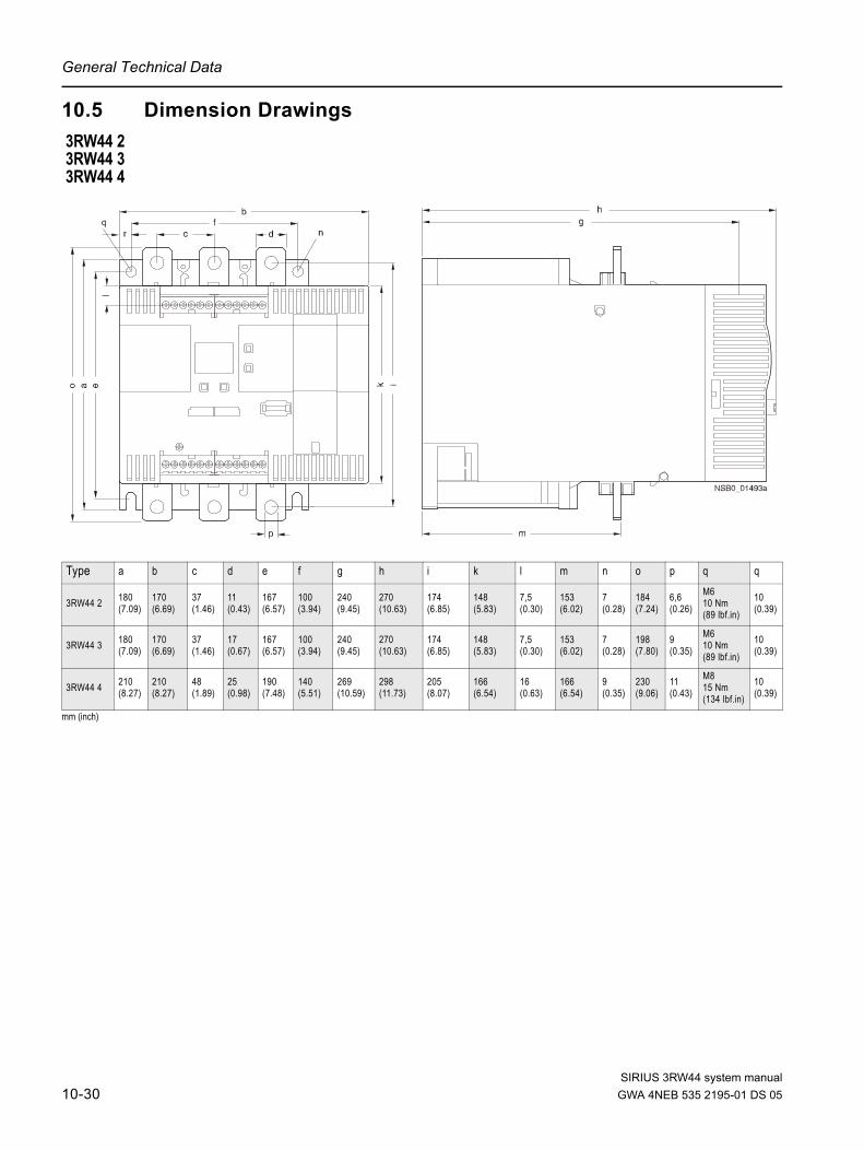
General Technical Data
10.5 Dimension Drawings
mm (inch)
3RW44 23RW44 33RW44 4
Type a b c d e f g h i k l m n o p q q
3RW44 2 180 (7.09)
170 (6.69)
37 (1.46)
11 (0.43)
167 (6.57)
100 (3.94)
240 (9.45)
270 (10.63)
174 (6.85)
148 (5.83)
7,5 (0.30)
153 (6.02)
7 (0.28)
184 (7.24)
6,6 (0.26)
M610 Nm(89 lbf.in)
10 (0.39)
3RW44 3 180 (7.09)
170 (6.69)
37 (1.46)
17 (0.67)
167 (6.57)
100 (3.94)
240 (9.45)
270 (10.63)
174 (6.85)
148 (5.83)
7,5 (0.30)
153 (6.02)
7 (0.28)
198 (7.80)
9 (0.35)
M610 Nm(89 lbf.in)
10 (0.39)
3RW44 4 210 (8.27)
210 (8.27)
48 (1.89)
25 (0.98)
190 (7.48)
140 (5.51)
269 (10.59)
298 (11.73)
205 (8.07)
166 (6.54)
16 (0.63)
166 (6.54)
9 (0.35)
230 (9.06)
11 (0.43)
M815 Nm(134 lbf.in)
10 (0.39)
SIRIUS 3RW44 system manual10-30 GWA 4NEB 535 2195-01 DS 05

General Technical Data
SIRIUS 3RW44 system manual
3RW44 5 / 3RW44 6
mm (inch)
mm (inch)
Type a b c d e f g h i k l m n
3RW44 5 76 (3)
40 (1.6)
14 (0.6)
20 (0.8)
15,5 (0.7)
638,5 (25.2)
590 (9.45) — 44
(1.8)470 (18)
510 (20)
16,5 (0.7)
105 (4.1)
3RW44 6 85 (3.35)
50 (1.97)
14 (0.6) — — 667
(26.3)660 (26)
160 (6.3)
37,5 (1.48)
535 (21)
576 (22.7)
16,5 (0.7)
103 (4.06)
Type o p q r s t u v w ad
3RW44 5 253 (10)
623 (24.6) — — — 249
(9.8)162 (6.4)
152 (5.9) — 290
3RW44 6 251 (9.88)
693 (27.3)
43,5 (1.71)
40 (1.6)
20 (0.78)
249 (9.8)
162 (6.4)
151,4 (5.96)
123 (4.84) 290
abc
i k
2T1 4T2
Ue=200...460V
G/031127 *E00*
NONONO NC NO
989695343324231413
5L3d.c./c.d. 24V
A1 A2 PE L+ L- IN1
1L1
T2T1IN4IN3IN2
230 V50 - 60 Hz
2T1 4T2 6T3
1L1 3L2 5L3
l
6T3
w
def g
h
mn
op
q
sr
t
uv
3RW44 6
3RW44 6
3RW44 6
3RW44 6
3RW44 6: M 12 ≤ 35 Nm / 310 lbf·in3RW44 5: M 12 ≤ 35 Nm / 310 lbf·in
Ø 13.5 mm (0.53 in)
ad
GWA 4NEB 535 2195-01 DS 05 10-31

General Technical Data
mm (inch)
Type x y z aa ab ac ad
3RW44 5 290 (11.4)
147 (5.7)
173 (6.9)
195 (7.7)
118 (4.6)
261 (10.2)
290 (11.5)
3RW44 6 289,5 (11.4)
175 (6.9)
173 (6.8) — 118
(4.65)261 (10.28)
290 (11.42)
x
yz
aa
abac
ad
3RW44 6
SIRIUS 3RW44 system manual10-32 GWA 4NEB 535 2195-01 DS 05

General Technical Data
SIRIUS 3RW44 system manual
External display and control module 3RW49 00-0AC00
Dimensions in mm (inch) Installation cutout for external display and control module 3RW49 00-0AC00
92 (3.62)
55 (2
.16)
(1.40)
(1.14)
(1.1)(3.78)
(2.3
6)
GWA 4NEB 535 2195-01 DS 05 10-33

General Technical Data
SIRIUS 3RW44 system manual10-34 GWA 4NEB 535 2195-01 DS 05

Configuration Data
Configuration DataSiemens AG
Technical Support Low-Voltage Control Systems
Tel.: +49 (0) 911-895-5900
Fax: +49 (0) 911-895-5907
E-mail: [email protected]
1. Motor data
Siemens motor? ..............................................................................................................................
Rated output: ............................................................................................................................ kW
Rated voltage: .............................................................................................................................. V
Line frequency: .......................................................................................................................... Hz
Rated current: .............................................................................................................................. A
Inrush current: .............................................................................................................................. A
Rated operating speed: ............................................................................................................. rpm
Rated operating torque:............................................................................................................. Nm
Stall torque: .............................................................................................................................. Nm
Mass moment of inertia: ....................................................................................................... kg*m2
Speed characteristic curve / torque characteristic curve
(The differences in speed of the value pairs do not have to be identical)
Speed characteristic curve / current characteristic curve
(The differences in speed of the value pairs do not have to be identical)
nM rpm "nsyn"
MM / MB
nM rpm "nsyn"
IM / IB
SIRIUS 3RW44 system manualGWA 4NEB 535 2195-01 DS 05 Configuration-1

Configuration Data
2. Load data
Load type (e.g. pump, mill, ...):........................................................................................................
Rated operating speed: ............................................................................................................. rpm
Rated operating torque or rated output.............................................................................Nm or kW
Mass moment of inertia (load-based) .....................................................................................kg*m2
Mass moment of inertia (motor-based) ...................................................................................kg*m2
Speed characteristic curve / torque characteristic curve
(The differences in speed of the value pairs do not have to be identical)
3. Start conditions
Start frequency....................................................................................................................... Starts
Operating cycle: Run-up time ........................................................................................................ s
Operating time .................................................................................................... s
Idle time.............................................................................................................. s
Stopping time...................................................................................................... s
Ambient temperature................................................................................................................... °C
4. Personal data
Surname, first name:.......................................................................................................................
Company: .......................................................................................................................................
Department: ....................................................................................................................................
Street: .............................................................................................................................................
Postal code, city:.............................................................................................................................
Country: ..........................................................................................................................................
Phone.: ...........................................................................................................................................
Fax: ................................................................................................................................................
E-mail: ............................................................................................................................................
nL rpm
ML / MB
Yes Value
Starting current limitation? ..........................
Acceleration torque limitation? ..........................
Maximum starting time? ..........................
SIRIUS 3RW44 system manualConfiguration-2 GWA 4NEB 535 2195-01 DS 05

Index
Numerics3-phase asynchronous motors 1-2, 6-203RW44 2. 3-113RW44 22 9-43RW44 25 9-43RW44 26 9-53RW44 3. 3-113RW44 4. 3-113RW44 47 9-5AAccessories 10-27Ambient temperature 2-6Application examples 2-3Applications 1-7, 6-2, 6-6Asymmetric limit value 6-20Asymmetry 6-20, 10-29Atmospheric pressure 10-4Automatic restart 3-4
BBranch layout 3-4Breakaway pulse 6-7Breakaway time 6-7Breakaway voltage 6-7Byte arrangements 8-40
CCapacitor 3-10CLASS 10 2-3, 6-21CLASS 10A 6-21CLASS setting 6-19, 6-20, 7-5, 10-12,
10-13, 10-14, 10-15Clearances 3-3Coasting down 2-3, 2-4, 5-21, 6-11Combined braking 5-25, 6-13Communication module PROFIBUS
DP 5-41, 7-3, 7-7, 8-1, 8-4, 8-7, 8-8, 8-9, 8-10, 8-14, 8-17, 8-18, 8-19, 10-27
Communication principle 8-6Component layout 10-21Conductor cross-sections 3-12Configuration 2-2Configuration with the GSD file 8-15Connection examples 9-2Connections 3-11Control circuit 9-2Control voltage versions 3-10Current asymmetry limit value 6-20Current limit values 5-27, 6-18
Current limiting 6-9Current limiting value 6-9
DData Formats 8-35Data sets 8-40Data transmission 8-6DC braking 5-24, 6-13, 6-14, 9-4, 9-5DC braking torque 6-13, 6-14Degree of protection 3-2Device errors 7-7Device interface 4-3Diagnosis 7-2Diagnosis via LED display 8-25Diagnosis with STEP 7 8-26Dimension drawings 10-30Direct on line starting 5-18Disconnector 3-4Display measured value 5-41Display settings 4-2, 5-33Display, see operating and monitoring
module 2-2Dynamic braking torque 6-13
EError 7-2Error codes for negative data set
acknowledgement 8-38Error messages 7-2Error types 8-34External display and control module
10-27, 10-33External display and control unit 4-3
FFactory settings 5-40
GGround fault 7-5Group error 7-2GSD file 8-15
HHeavy starting 2-3
IIdle time 6-20, 6-21Inching 6-20Inherent protection 6-23Inside delta circuit 3-6, 9-6Installation altitude 2-6
SIRIUS 3RW44 system GWA 4NEB 535 2195-02 DS 05 Index-1

Internal run-up recognition 6-3, 6-5
LLimiting torque 6-5Line contactor 9-3Line voltage 3-6
MMain circuit 9-2Main contactor 3-8Main current connection 3-11Maximum pointer 8-37Maximum starting time 6-3Menu structure 5-2, 10-2Messages 7-2Motor control 5-43Motor data 5-11motor heat build-up 6-20Motor heating 5-19, 6-10Motor overload protection 6-19Motor protection function 6-19Motor protection settings 5-31Motor starter configuration 8-15Mounting Dimensions 3-3Mounting position 3-2
NNavigation 5-2Normal or Heavy Starting 2-3Normal starting 2-3
OOn-time motor 2-5Operating and monitoring module, see
display 2-2Overtemperature 7-5
PParameter 5-2Parameter sets 5-10, 6-2Parameterizing the inputs 5-28Parameterizing the outputs 5-29PC interface 2-2Phase loss 7-3PLC 3-4, 4-2, 5-43, 7-5, 8-37, 8-41, 8-49,
8-51, 8-55, 8-60, 8-62, 8-66, 8-67, 8-68, 8-69, 9-3
Prewarning limit 6-20PROFIBUS 10-27Profibus 4-3Profibus interface 4-3Protection against voltage failure 6-21Protective functions 5-34PTC thermistors 6-22
Pump stop 5-23, 6-12
QQuick start menu 5-6, 5-7
RRated motor current 3-6Rated operating speed 6-16Rated operating torque 5-12Reduce starting current 1-2Relative humidity 10-4Restart 3-4Restore basic factory settings 2-7, 5-40Reversed direction of rotation 9-6Reversing operation 9-10Run-up recognition 6-3, 6-5, 6-9, 6-10
SSafety 5-48Save settings 5-38Saving options 5-37Screw-type terminals 3-10Selection criteria 1-7Semiconductor fuse 3-9, 6-23Semiconductor protection 9-2Settings 5-9, 5-38, 5-39SITOR 3-9, 6-23SITOR fuses 3-9SITOR semiconductor fuse 6-23Slow speed factor 6-16Slow speed function 6-16, 9-8Slow speed parameters 5-26Slow speed torque 6-16Soft Starter ES 10-27Soft starters
for high-feature applicationsBox terminal block 10-28Covers 10-28Fans 10-28PC cable 10-27Software 10-27
Soft stop 5-22Software 2-2, 4-3Spare parts 10-28Spring-loaded terminals 3-10Standard circuit 3-5, 9-2Standards 3-2Start torque 1-2, 1-4, 6-3, 6-5, 6-7Start voltage 6-3Starting 1-6Starting current 1-2Starting mode 5-13Starting the motor starter 8-22Starting time 6-3, 6-5
SIRIUS 3RW44 system manualIndex-2 GWA 4NEB 535 2195-02 DS 05

Status diagram 5-30Stopping modes 5-20, 6-11Stopping time 6-12, 6-14, 6-15Stopping torque 6-12Storage temperature 10-4Supply voltage 7-4Switching element 3-4Switching frequency 2-5Symmetry 10-29
TTechnical data 10-5
Control unit 10-16Power unit 10-12
Temperature 10-4Temperature sensor 6-22Thermo click 6-22Torque control 5-16, 5-22, 6-5Torque control with current limiting 5-17Transport and storage conditions 10-4Tripping characteristics 10-29Tripping class 6-19, 6-20
UUnpacking 3-2User-specific commissioning 5-8
VVery heavy starting 2-4Voltage ramp 5-14, 6-3, 6-4Voltage ramp with current limiting 5-15
WWarnings 7-2Water hammer 6-12
SIRIUS 3RW44 system manualGWA 4NEB 535 2195-02 DS 05 Index-3

SIRIUS 3RW44 system manualIndex-4 GWA 4NEB 535 2195-02 DS 05

SIRIUS 3RW44 system manualGWA 4NEB 535 2195-01 DS 05 Fax-1
ToSIEMENS AGA&D CD MM 3
92220 Amberg, Germany
Fax: 09621 / 80-3337
SIRIUS 3RW44 Soft Starters System Manual
Have you noticed any errors while reading this manual? Please use this form to inform us about any errors.All complaints and suggestions for improvements are very welcome.
Sender (please fill in)
Name
Company / department
Address
Telephone
Fax