Embed Size (px)
Citation preview

Article
Soft Roof Failure Mechanism and Supporting Methodfor Gob-Side Entry Retaining
Hongyun Yang 1,2, Shugang Cao 1,2,*, Yong Li 1,2, Chuanmeng Sun 1,2,3 and Ping Guo 4
Received: 12 May 2015 ; Accepted: 20 October 2015 ; Published: 28 October 2015Academic Editor: Saiied Aminossadati
1 State Key Laboratory of Coal Mine Disaster Dynamics and Control, Chongqing University,Chongqing 400044, China; [email protected] (H.Y.); [email protected] (Y.L.); [email protected] (C.S.)
2 College of Resources and Environmental Science, Chongqing University, Chongqing 400044, China3 School of Computer Science and Control Engineering, North University of China, Taiyuan 030051, China4 National Key Laboratory of Gas Disaster Detecting, Preventing and Emergency Controlling,
China Coal Technology Engineering Group Chongqing Research Institute, Chongqing 400037, China;[email protected]
* Correspondence: [email protected]; Tel./Fax: +86-23-6511-1706
Abstract: To study the soft roof failure mechanism and the supporting method for a gateway in agently inclined coal seam with a dip angle of 16˝ kept for gob-side entry retaining, and through themethodology of field investigation and numerical and analytical modeling, this paper analyzedthe stress evolution law of roof strata at the working face end and determined that the sharphorizontal stress unloading phenomenon along the coal wall side did not appear after the workingface advanced. Conversely, the horizontal stress along the gob side instantly decreased and thetensile stress produced, and the vertical stress in the central part of the roof had a higher reductionmagnitude as well. An in-depth study indicates that the soft roof of the working face end subsidedand seriously separated due to the effect of the front abutment pressure and the roof hanging lengthabove the gob line, as well as certain other factors, including the rapid unloading of the lateralstress, tension and shear on the lower roof rock layer and dynamic disturbance. Those influencingfactors also led to rapid crack propagation on a large scale and serious fracturing in the soft roof ofthe working face end. However, in the gob stress stabilized zone, the soft roof in the gob-side entryretaining has a shearing failure along the filling wall inside affected by the overburden pressure, rockbulking pressure, and roof gravity. To maintain the roof integrity, decrease the roof deformation,and enable the control of the working face end soft roof and the stabilization of the gob-side entryretaining roof, this study suggests that the preferred bolt installation angle for the soft roof situationis 70˝ based on the rock bolt extrusion strengthening theory.
Keywords: gob-side entry retaining; unloading loose; bolt installation angle;extrusion strengthening
1. Introduction
The retaining of the gob-side entry is to maintain the head entry of current mining panel behindthe working face to be reused for the next panel as the tail entry. This technology can effectivelyincrease the coal recovery rate, reduce the roadway development rate, and mitigate the outburst risk,as no pillar is needed for the retained entry, but rather an artificial filling wall is constructed on thegob side with a special support for entry stability [1].
Since the 1950s, pillarless roadways have been constructed worldwide, and extensive studieshave been carried out on support resistance [2,3]. Previous studies showed that the gateway roofrock mass failure mechanism and supporting methods have a significant impact on gob-side entry
Minerals 2015, 5, 707–722; doi:10.3390/min5040519 www.mdpi.com/journal/minerals

Minerals 2015, 5, 707–722
retaining, determining the procedure’s success. Many researchers categorized five failure types of agateway roof rock mass, including the compressive stress failure type, tensile stress failure type, shearstress failure type, squeezing and fluidity failure type, and geological structure failure type [4–6].Based on the above failure mechanism of gateway roof strata, many active support models weresuggested, and a combined supporting technology using a bolt, mesh, and cable was found to beeffective for ground control. It was found that a combined support is unable to control the mainroof in roadway retaining according to the theory of “given deformation”, but it can stabilize theimmediate roof with the main roof to maintain the retained gob-side entry very well [7,8].
Rock bolts have become a popular technique for reinforcing rock masses all over the world. Rockbolts are installed to reinforce a fractured rock mass by resisting dilation or shear movement along thefractures. Nemcik et al. [9] determined that the non-linear bond-slip relationship used in the FLACmodel for bolting accurately matches the experimental data reported by Ma et al. [10]. Yang [11]divided the anchored force evolution process into three stages and found that a surface structure-likebearing plate produces a maximum anchorage force acting directly on the surface of rock that canprovide the greatest degree of support. This not only improved the rock mass stress state but alsoincreased the thickness of the reinforcement structure formed by the anchoring force. Zheng andZhang [12] determined the shear stress and pressure stress distribution equation for the anchoredsegment and upon studying the stress distribution rule of anchored segment, found that the effect ofthe pre-tensioned bolt in the soft rock was superior to that in hard rock. Cao [13] showed that theintegrity of the supporting system that prevents local failure of surrounding rock from progressinginto overall failure is important in rock bolting, so that reinforcing measures should be taken whennecessary. Fan [14] designed a roadway heterogeneity controlling technology on a siltstone roof.Hua [15] made use of bolt support and anchor cable reinforcement support technologies insideand beside a retained roadway, respectively, and maintained the retained gob-side entry very well.Yan [16] used pre-tensioned bolts on a roadway roof with medium and fine-grained sandstones by anextrusion lockset to limit its vertical deformation for entry integrity and also analyzed the mechanicalmechanism, technical principle and technical characteristics of bolt and cable coupling supports at amine site. Chen and Bai [17] used bolts with high pre-tensioning, high strength, and a large elongationrate and cables as the basic supporting element, a single hydraulic prop with a metal hinge top beamas a reinforcement support inside the roadway, and a high-water rapid-solidifying material to supportthe side of the roadway to effectively control the roof rock deformation with medium and fine-grainedsandstones in gob-side entry retaining.
In the past experimental studies and supporting theory [4,14–17], the bolt support is mainlyaimed at the control of the medium-hard roof rock mass, which are generally medium andfine-grained sandstones in the horizontal and flat seams. The supporting theory also providessupporting references for the similar conditions of the roadway in the initial excavation stage andretaining stage. However, the working face end roof and retained roadway roof seriously deformedin the soft roof rock mass and gentle inclined coal seam with a soft roof rock after referencingthe existed supporting theory. Therefore, to further develop our understanding of the soft rooffailure mechanism and provide a supporting method, the following works were conducted in thisarticle. First, the roof failure phenomenon of a gently inclined coal seam working face end andretained roadway were investigated at a coal mine in the southwest of China. Second, the rooffailure mechanism was analyzed through the field investigation and stress evolution law obtainedby three-dimensional distinct element code (3DEC). Finally, a roof support was designed based onresults of this investigation to maintain roadway stability.
2. Description of Field Observation
2.1. Survey of Study Site
The target coal mine is located in the southwest of China. The mining coal seam is #C19, with anaverage dip angle of 16˝ and a mining thickness of 1.1 m. The mining method is the fully mechanized
708

Minerals 2015, 5, 707–722
longwall, and gob side entry retaining is used, as shown in Figure 1a. The investigated head entryis buried at 315 m, with a cross-section of 3.8 m in width and 2.1 m in height of the short rib, whereresin-anchored rock bolts (Φ20 ˆ 2200 mm), cables (Φ12.54 ˆ 6300 mm), and reinforcement meshwere used, and three rows of single hydraulic supports with top hinged beams were used as advancedstrengthening support, as shown in Figure 1b. The roof rock bolts are non-fully anchored (anchorlength is 1.4 m) with a pre-tension of 90 kN, inter-row spacing of 800 ˆ 800 mm and bolt angles of90˝, 80˝, 70˝, and 60˝ for different bolts, and the extra cables have a pre-tension of 200 kN and aninter-row spacing of 3200 ˆ 1200 mm.
Minerals 2015, 5, page–page
3
used, and three rows of single hydraulic supports with top hinged beams were used as advanced strengthening support, as shown in Figure 1b. The roof rock bolts are non-fully anchored (anchor length is 1.4 m) with a pre-tension of 90 kN, inter-row spacing of 800 × 800 mm and bolt angles of 90°, 80°, 70°, and 60° for different bolts, and the extra cables have a pre-tension of 200 kN and an inter-row spacing of 3200 × 1200 mm.
Figure 1. (a) Schematic of gob-side entry retaining; (b) Schematic of advanced strengthening support.
According to a geological survey, the gateway roof strata typically consist of weak rocks. The immediate roof is approximately 1.0 m in thickness and is made up of sandy mudstone and mudstone. The main roof consists of more competent siltstones and silty mudstones containing siderite nodules. In other words, the roof strata have low strength and poor stability and exhibit clear stratification, thus resulting in an immediate roof caving with the working face advancing as well as part of the main roof. Also, the floor is made up of sandy mudstone. It must be stressed that, at the working face end, the gateway soft roof was often affected by dynamic loading for the following reasons: (1) caving of the overburden rock mass in the gob roof, and the gangue movement, collision; (2) periodic weighting of the main roof; and (3) blasting operations of adjacent mining and excavating faces.
2.2. The Survey Results of Soft Roof Failure Characteristics
The soft roof failure characteristics of the front abutment pressure zone, the stress decreasing zone, and the stress stability zone are shown in Figure 2. According to a filed investigation of the head entry, there was a serious roof deformation due to the impact of front abutment pressure and a few cracks with less opening over a small area of the roof surface, as shown in Figure 2a. With the working face advancing, the roof overhanging length increased, and cracks formed and joined together in the roof rock mass, as shown in Figure 2b, resulting in a decrease of the roof strength, loss of self-bearing capacity, separation from the main roof, and roof deformation and becoming unload rock body, especially for the rock mass indicated by the red line. In addition, two bolts and one cable (B1, B2 and C1) on the gob side lost their support ability. After building the filling wall and removing the supports in the stress stability zone, the roof fractured along the inside of the filling wall, indicated as the “fracture line” in Figure 2c.
Field observations found that there were a large number of cracks in the vertical direction of roof near the end of the working face, so the roof caving occurred generally within a height range of 1.5 to 2 m, as shown in Figure 3.
Figure 1. (a) Schematic of gob-side entry retaining; (b) Schematic of advanced strengthening support.
According to a geological survey, the gateway roof strata typically consist of weak rocks.The immediate roof is approximately 1.0 m in thickness and is made up of sandy mudstone andmudstone. The main roof consists of more competent siltstones and silty mudstones containingsiderite nodules. In other words, the roof strata have low strength and poor stability and exhibitclear stratification, thus resulting in an immediate roof caving with the working face advancing aswell as part of the main roof. Also, the floor is made up of sandy mudstone. It must be stressedthat, at the working face end, the gateway soft roof was often affected by dynamic loading for thefollowing reasons: (1) caving of the overburden rock mass in the gob roof, and the gangue movement,collision; (2) periodic weighting of the main roof; and (3) blasting operations of adjacent mining andexcavating faces.
2.2. The Survey Results of Soft Roof Failure Characteristics
The soft roof failure characteristics of the front abutment pressure zone, the stress decreasingzone, and the stress stability zone are shown in Figure 2. According to a filed investigation of thehead entry, there was a serious roof deformation due to the impact of front abutment pressure anda few cracks with less opening over a small area of the roof surface, as shown in Figure 2a. Withthe working face advancing, the roof overhanging length increased, and cracks formed and joinedtogether in the roof rock mass, as shown in Figure 2b, resulting in a decrease of the roof strength, lossof self-bearing capacity, separation from the main roof, and roof deformation and becoming unloadrock body, especially for the rock mass indicated by the red line. In addition, two bolts and one cable(B1, B2 and C1) on the gob side lost their support ability. After building the filling wall and removingthe supports in the stress stability zone, the roof fractured along the inside of the filling wall, indicatedas the “fracture line” in Figure 2c.
Field observations found that there were a large number of cracks in the vertical direction of roofnear the end of the working face, so the roof caving occurred generally within a height range of 1.5 to2 m, as shown in Figure 3.
709

Minerals 2015, 5, 707–722Minerals 2015, 5, page–page
4
Figure 2. Schematic of soft roof rock mass failure; (a) In front abutment pressure zone; (b) In working face end; (c) In stress stability zone of retaining gateway.
Figure 3. Caving roof near the working face end.
3. Stress Evolution Law in Roof
To analyze the stress evolution law in the roof, the numerical modeling was adopted.
3.1. Numerical Simulation Model
Because of the coal seam condition and as the rock mass was discontinuous [18,19], 3DEC of ITASCA (Minneapolis, MN, USA) [20,21] was used to study the stress evolution law in the roof. The hexahedral model has a length, width, and height of 230 m, 100 m, and 200 m, respectively, includes coal seams and rock strata, with a total of 14 layers, as shown in Figure 4, in accordance with the geological conditions of the investigated mine. The Mohr-Coulomb yield criterion for the materials and the Coulomb slip model for contact were used. The mechanical and physical properties of all the layers and the contacts between every two layers are described in [13,22], respectively.
According to the reference [23], the minimum coefficient of lateral pressure is very close to 0 and the maximum can be up to 6 due to tectonic movement. For this case, we consider the coefficient of lateral pressure is 0.5, as the gateway is placed at shallow depth and close to the anticline axis and seam outcrop, which resulting in a much low horizontal stress. So, the state of the in situ stresses is σx = σy = 4.25 MPa and σz = 8.5 MPa, with σy parallel to the longwall advance direction and σx perpendicular, as shown in Figure 4b. A vertical pressure of 8.5 MPa is applied on the top surface, and the velocity of the bottom surface was restricted in all three directions, vx = vy = vz = 0 m/s. The velocity of the other four surfaces were restricted in the normal direction vn = 0 m/s.
The shape and size of the head entry are introduced in Section 2.1. After an initial equilibrium calculation, rock bolts were installed, as shown in Figure 1b, once the head was entry excavated. The rock bolts were represented as built-in “cable” elements. For resin-grouted rock bolts, the stiffness (Kbond) and the cohesive strength (Sbond) of the grout are the two key properties that govern the anchor characteristics [22]; Kbond = 3.06 × 10⁹ N/m/m and Sbond = 2.3 × 10⁵ kN/m were adopted in this study. In addition, a cross-sectional area of 3.142 × 10⁻⁴ m2, an elastic modulus of 200 GPa, and a tensile yield
Figure 2. Schematic of soft roof rock mass failure; (a) In front abutment pressure zone; (b) In workingface end; (c) In stress stability zone of retaining gateway.
Minerals 2015, 5, page–page
4
Figure 2. Schematic of soft roof rock mass failure; (a) In front abutment pressure zone; (b) In working face end; (c) In stress stability zone of retaining gateway.
Figure 3. Caving roof near the working face end.
3. Stress Evolution Law in Roof
To analyze the stress evolution law in the roof, the numerical modeling was adopted.
3.1. Numerical Simulation Model
Because of the coal seam condition and as the rock mass was discontinuous [18,19], 3DEC of ITASCA (Minneapolis, MN, USA) [20,21] was used to study the stress evolution law in the roof. The hexahedral model has a length, width, and height of 230 m, 100 m, and 200 m, respectively, includes coal seams and rock strata, with a total of 14 layers, as shown in Figure 4, in accordance with the geological conditions of the investigated mine. The Mohr-Coulomb yield criterion for the materials and the Coulomb slip model for contact were used. The mechanical and physical properties of all the layers and the contacts between every two layers are described in [13,22], respectively.
According to the reference [23], the minimum coefficient of lateral pressure is very close to 0 and the maximum can be up to 6 due to tectonic movement. For this case, we consider the coefficient of lateral pressure is 0.5, as the gateway is placed at shallow depth and close to the anticline axis and seam outcrop, which resulting in a much low horizontal stress. So, the state of the in situ stresses is σx = σy = 4.25 MPa and σz = 8.5 MPa, with σy parallel to the longwall advance direction and σx perpendicular, as shown in Figure 4b. A vertical pressure of 8.5 MPa is applied on the top surface, and the velocity of the bottom surface was restricted in all three directions, vx = vy = vz = 0 m/s. The velocity of the other four surfaces were restricted in the normal direction vn = 0 m/s.
The shape and size of the head entry are introduced in Section 2.1. After an initial equilibrium calculation, rock bolts were installed, as shown in Figure 1b, once the head was entry excavated. The rock bolts were represented as built-in “cable” elements. For resin-grouted rock bolts, the stiffness (Kbond) and the cohesive strength (Sbond) of the grout are the two key properties that govern the anchor characteristics [22]; Kbond = 3.06 × 10⁹ N/m/m and Sbond = 2.3 × 10⁵ kN/m were adopted in this study. In addition, a cross-sectional area of 3.142 × 10⁻⁴ m2, an elastic modulus of 200 GPa, and a tensile yield
Figure 3. Caving roof near the working face end.
3. Stress Evolution Law in Roof
To analyze the stress evolution law in the roof, the numerical modeling was adopted.
3.1. Numerical Simulation Model
Because of the coal seam condition and as the rock mass was discontinuous [18,19], 3DEC ofITASCA (Minneapolis, MN, USA) [20,21] was used to study the stress evolution law in the roof. Thehexahedral model has a length, width, and height of 230 m, 100 m, and 200 m, respectively, includescoal seams and rock strata, with a total of 14 layers, as shown in Figure 4, in accordance with thegeological conditions of the investigated mine. The Mohr-Coulomb yield criterion for the materialsand the Coulomb slip model for contact were used. The mechanical and physical properties of all thelayers and the contacts between every two layers are described in [13,22], respectively.
According to the reference [23], the minimum coefficient of lateral pressure is very close to 0 andthe maximum can be up to 6 due to tectonic movement. For this case, we consider the coefficient oflateral pressure is 0.5, as the gateway is placed at shallow depth and close to the anticline axis andseam outcrop, which resulting in a much low horizontal stress. So, the state of the in situ stressesis σx = σy = 4.25 MPa and σz = 8.5 MPa, with σy parallel to the longwall advance direction and σx
perpendicular, as shown in Figure 4b. A vertical pressure of 8.5 MPa is applied on the top surface,and the velocity of the bottom surface was restricted in all three directions, vx = vy = vz = 0 m/s. Thevelocity of the other four surfaces were restricted in the normal direction vn = 0 m/s.
The shape and size of the head entry are introduced in Section 2.1. After an initial equilibriumcalculation, rock bolts were installed, as shown in Figure 1b, once the head was entry excavated. Therock bolts were represented as built-in “cable” elements. For resin-grouted rock bolts, the stiffness(Kbond) and the cohesive strength (Sbond) of the grout are the two key properties that govern theanchor characteristics [22]; Kbond = 3.06 ˆ 109 N/m/m and Sbond = 2.3 ˆ 105 kN/m were adopted inthis study. In addition, a cross-sectional area of 3.142 ˆ 10´4 m2, an elastic modulus of 200 GPa, and
710

Minerals 2015, 5, 707–722
a tensile yield strength of 165 kN were assigned to the “cable” element. A stepwise excavation in they-direction was adopted to simulate the working face advancing by deleting blocks in five steps of10 m each, as shown in Figure 4c.
Minerals 2015, 5, page–page
5
strength of 165 kN were assigned to the “cable” element. A stepwise excavation in the y-direction was adopted to simulate the working face advancing by deleting blocks in five steps of 10 m each, as shown in Figure 4c.
Figure 4. (a) Numerical model; (b) Coal seam mining model; (c) Working face advancing; (d) Immediate roof grid, bolt and monitoring points; (e) Gateway cross section of model.
3.2. Numerical Results
To understand the stress evolution law, the horizontal stresses in the x-direction of points A1 and A3 and the vertical stress of point A2 in the roof at y = 45 m, as shown in Figure 4d, were monitored during the working face advancing, and the results are shown in Figure 5. Especially, it can be found that from A to B Zone, the horizontal stress on the coal side (A3) increases slightly in magnitude and then reduces to approximately 5.9 MPa, while the horizontal stress on the gob side (A1) drops instantaneously and appears tensile, and the vertical stress at the gateway central (A2) reduces significantly to 4.5 MPa as soon as the working face advances beyond the monitor points. The stresses in the gateway roof changed over the whole process from the beginning of the caving to the roof stabilization, until a tensile state was reached, which will influence the stability of the gob-side entry retaining.
Figure 5. Roof rock mass stress evolution law in working face end.
4. Force States of Roof Rock Mass
Here, combining with the numerical results and field investigation results, the force states of roof rock mass was analyzed to facilitate the failure mechanism analysis of roof rock mass and later theoretical analysis of supporting.
The stress evolution law showed in Figure 5 experienced the front abutment pressure zone (section A-A in Figure 1) and stress decreasing zone (section B-B in Figure 1). In section A-A, there are lateral forces F1a and F1b parallel to the rock strata and an overburden pressure P1 resembling the stress
Figure 4. (a) Numerical model; (b) Coal seam mining model; (c) Working face advancing; (d)Immediate roof grid, bolt and monitoring points; (e) Gateway cross section of model.
3.2. Numerical Results
To understand the stress evolution law, the horizontal stresses in the x-direction of points A1
and A3 and the vertical stress of point A2 in the roof at y = 45 m, as shown in Figure 4d, weremonitored during the working face advancing, and the results are shown in Figure 5. Especially,it can be found that from A to B Zone, the horizontal stress on the coal side (A3) increases slightly inmagnitude and then reduces to approximately 5.9 MPa, while the horizontal stress on the gob side(A1) drops instantaneously and appears tensile, and the vertical stress at the gateway central (A2)reduces significantly to 4.5 MPa as soon as the working face advances beyond the monitor points.The stresses in the gateway roof changed over the whole process from the beginning of the cavingto the roof stabilization, until a tensile state was reached, which will influence the stability of thegob-side entry retaining.
Minerals 2015, 5, page–page
5
strength of 165 kN were assigned to the “cable” element. A stepwise excavation in the y-direction was adopted to simulate the working face advancing by deleting blocks in five steps of 10 m each, as shown in Figure 4c.
Figure 4. (a) Numerical model; (b) Coal seam mining model; (c) Working face advancing; (d) Immediate roof grid, bolt and monitoring points; (e) Gateway cross section of model.
3.2. Numerical Results
To understand the stress evolution law, the horizontal stresses in the x-direction of points A1 and A3 and the vertical stress of point A2 in the roof at y = 45 m, as shown in Figure 4d, were monitored during the working face advancing, and the results are shown in Figure 5. Especially, it can be found that from A to B Zone, the horizontal stress on the coal side (A3) increases slightly in magnitude and then reduces to approximately 5.9 MPa, while the horizontal stress on the gob side (A1) drops instantaneously and appears tensile, and the vertical stress at the gateway central (A2) reduces significantly to 4.5 MPa as soon as the working face advances beyond the monitor points. The stresses in the gateway roof changed over the whole process from the beginning of the caving to the roof stabilization, until a tensile state was reached, which will influence the stability of the gob-side entry retaining.
Figure 5. Roof rock mass stress evolution law in working face end.
4. Force States of Roof Rock Mass
Here, combining with the numerical results and field investigation results, the force states of roof rock mass was analyzed to facilitate the failure mechanism analysis of roof rock mass and later theoretical analysis of supporting.
The stress evolution law showed in Figure 5 experienced the front abutment pressure zone (section A-A in Figure 1) and stress decreasing zone (section B-B in Figure 1). In section A-A, there are lateral forces F1a and F1b parallel to the rock strata and an overburden pressure P1 resembling the stress
Figure 5. Roof rock mass stress evolution law in working face end.
4. Force States of Roof Rock Mass
Here, combining with the numerical results and field investigation results, the force states ofroof rock mass was analyzed to facilitate the failure mechanism analysis of roof rock mass and latertheoretical analysis of supporting.
The stress evolution law showed in Figure 5 experienced the front abutment pressure zone(section A-A in Figure 1) and stress decreasing zone (section B-B in Figure 1). In section A-A, thereare lateral forces F1a and F1b parallel to the rock strata and an overburden pressure P1 resembling the
711

Minerals 2015, 5, 707–722
stress (A1, A2 and A3) in A Zone in Figure 5. In addition, field investigation showed that, there arebolt, mesh, and cable support force T1, reinforced supporting force R1 in advance, shear forces Q1a,Q1b on the two sides and gravity G. The force state was shown in Figure 6a.
In section B-B, the gob side lateral force disappears along the strata strike direction resemblingthe stress (A1) in B Zone in Figure 5, because of the roof rock mass caving near the gob side and partof the roof rock mass fracturing, but the coal side lateral force is F2b resembling the stress (A3) in BZone in Figure 5. On the other hand, the overburden of pressure is assumed to become 0 resemblingthe stress (A2) in B Zone in Figure 5, due to the roof separating from main roof. There are also a bolt,mesh, and cable support force T2, a strengthen support force R2 at the working face end and a shearforce Q2b in field, also the gravity G. The force state was shown in Figure 6b.
Furthermore, the roof rock mass stress in cross section C-C (in Figure 1) has experienced thestress states of sections A-A and B-B, but, field investigation showed that it will change after theconstruction of the artificial filling wall and the main roof rotary sinking, and the lateral force Fa onthe coal side and the overburden pressure P will restore, the lateral force on the gob side will changeto Fb. In addition, the bolt, mesh and cable support force become to T, the shear forces at the two endsbecome to Q1a and Q1b and gravity remain the same G. The force state was shown in Figure 6c.
Minerals 2015, 5, page–page
6
(A1, A2 and A3) in A Zone in Figure 5. In addition, field investigation showed that, there are bolt, mesh, and cable support force T1, reinforced supporting force R1 in advance, shear forces Q1a, Q1b on the two sides and gravity G. The force state was shown in Figure 6a.
In section B-B, the gob side lateral force disappears along the strata strike direction resembling the stress (A1) in B Zone in Figure 5, because of the roof rock mass caving near the gob side and part of the roof rock mass fracturing, but the coal side lateral force is F2b resembling the stress (A3) in B Zone in Figure 5. On the other hand, the overburden of pressure is assumed to become 0 resembling the stress (A2) in B Zone in Figure 5, due to the roof separating from main roof. There are also a bolt, mesh, and cable support force T2, a strengthen support force R2 at the working face end and a shear force Q2b in field, also the gravity G. The force state was shown in Figure 6b.
Furthermore, the roof rock mass stress in cross section C-C (in Figure 1) has experienced the stress states of sections A-A and B-B, but, field investigation showed that it will change after the construction of the artificial filling wall and the main roof rotary sinking, and the lateral force Fa on the coal side and the overburden pressure P will restore, the lateral force on the gob side will change to Fb. In addition, the bolt, mesh and cable support force become to T, the shear forces at the two ends become to Q1a and Q1b and gravity remain the same G. The force state was shown in Figure 6c.
Figure 6. Roof rock mass force; (a) Force of cross section A-A; (b) Force of cross section B-B; (c) Force of cross section C-C.
5. Mechanism for Failure of Roof Rock Mass
Roof failure was affected by many factors, so we will combine them with the failure characteristics obtained by filed investigation, stress evolution law obtained by numerical modeling and the force states to study the roof failure mechanism.
5.1. Mechanism for Failure of Roof Rock Mass in Working Face End
5.1.1. Unloading Effect of the Lateral Stress
Affected by the abutment pressure in the mining and excavation process, the roof rock mass is in the yield state, as shown in cross section A-A in Figure 1. The pre-tensioned bolt-cable-mesh supporting system improved the strength, significantly increased the yield strength, and altered the deformation characteristics of the roof rock mass. At the same time, the support system exerted a pressure stress on the rock mass, so the compressive zone stress state had to be altered, which can offset some of the tensile stress and friction and enhance the shear capacity. In addition, the axial and lateral anchored forces increased the shear strength of the weak structural plane, preventing the roof rock mass from moving and sliding along the block structure plane. The pre-tensioned support system controlled the expansion deformation and destruction, preventing roof separation, sliding, fracture opening, and new crack generation in the anchorage zones, not only maintaining the integrity but also forming a pre-tensioned bearing structure with a large stiffness [24,25].
Figure 6. Roof rock mass force; (a) Force of cross section A-A; (b) Force of cross section B-B; (c) Forceof cross section C-C.
5. Mechanism for Failure of Roof Rock Mass
Roof failure was affected by many factors, so we will combine them with the failurecharacteristics obtained by filed investigation, stress evolution law obtained by numerical modelingand the force states to study the roof failure mechanism.
5.1. Mechanism for Failure of Roof Rock Mass in Working Face End
5.1.1. Unloading Effect of the Lateral Stress
Affected by the abutment pressure in the mining and excavation process, the roof rock massis in the yield state, as shown in cross section A-A in Figure 1. The pre-tensioned bolt-cable-meshsupporting system improved the strength, significantly increased the yield strength, and altered thedeformation characteristics of the roof rock mass. At the same time, the support system exerted apressure stress on the rock mass, so the compressive zone stress state had to be altered, which canoffset some of the tensile stress and friction and enhance the shear capacity. In addition, the axialand lateral anchored forces increased the shear strength of the weak structural plane, preventing theroof rock mass from moving and sliding along the block structure plane. The pre-tensioned supportsystem controlled the expansion deformation and destruction, preventing roof separation, sliding,fracture opening, and new crack generation in the anchorage zones, not only maintaining the integritybut also forming a pre-tensioned bearing structure with a large stiffness [24,25].
712

Minerals 2015, 5, 707–722
Influenced by the rotary sinking of the overlying roof and the superposition of the overburdenpressure, the vertical displacement of the anchor bolt and cable increased significantly, leading to anincrease of T1. The stress increment of the roadway roof rock mass mainly comes from the bulkingdeformation. When the bolt, mesh, and cable apply pressure on the broken rock mass and adds ananchoring force, the rock mass volume or volume rise rate decrease, and a bulking force is producedby the broken rock mass that would work the bolts and surrounding rock at the same time and put theroof rock mass in an extrusion state. As shown in cross section A-A in Figure 1, it is precisely becauseof the interaction of the “support-surrounding rock”, that the roof rock mass presented a failure statein Figure 2a.
Although the single hydraulic props support the roof strata with pressure, the extrusion staterock mass above the hydraulic support started loosening on the working face end. In cross sectionB-B in Figure 1, the loosening roof rock mass caved behind the support body on the gob side, causinga sharp reduction of the lateral pressure, especially for the accumulated bulking force. Meanwhile,the overburden pressure decreased almost to 0 due to the separation of the soft roof from the hardroof above.
It can be observed that, accompanied by the gob roof caving, the lateral pressure unloaded andthe bulking force decreased in the broken rock mass of the roadway roof, leading to its stress statechanging from a three-dimensional stress state to a two-dimensional or uniaxial stress state, leadingmore easily to failure. At this point, together with the tensile stress effect, the rock mass volume“elastic” expansion in the layer strike direction caused the generation and propagation of a largenumber of cracks and the further failure of the rock mass.
5.1.2. Tensile and Shear Failure of the Working Face End Lower Layer Rock Mass
Through the field investigation of the roof support body layout and its work process and basedon the features of the roof rock mass deformation and failure, it is found that the working face endsoft roof presents the following phenomenon:
(1) An uneven supporting at the working face end roof. A strong mine ground pressure appeared,causing the significant sinking of the working face end roof in the working face advancingprocess, so a single hydraulic prop with an articulated roof beam was usually set as areinforcement support. There is uneven pressure on the roof surface due to the low strengthand stiffness of the sandy mudstone and mudstone and the higher strength and stiffnessstrengthening the support body, resulting in part of the support body inserting the roof andleading to a roof rock shear failure with shear stress q, as shown in Figure 7. In addition,the passive supporting force is too large and does not couple support with the bolts (cables),causing part of the bolts (cables) to be loosened, affecting the roof rock mass local stress stateand resulting in ultimate rock mass failure.
(2) Effect of local moment. Treating the reinforcement body (individual hydraulic prop andarticulated roof beam, etc.) as the fulcrum, the lower roof strata produced a local bending ona small scale, but when the fulcrum bending moment (M) is too large, the layered roof stratacause tensile and compressive damage to the upper surface and lower surface, respectively,additionally increased the possibility of the support body inserting the upper roof and leadingto rock mass shear failure, as shown in Figure 7.
The two phenomena above are shown in the Figure 1 A-A and B-B cross sections and mayoccur simultaneously.
5.1.3. Dynamic Failure
The working face end roof rock mass is often affected by vibration as described above. Here,3DEC was also applied to study the dynamic failure characteristics of the roof rock mass, thecoal and rock mass physical and mechanical parameters and the boundary conditions used in the
713

Minerals 2015, 5, 707–722
numerical model shown in Figure 4, additionally adding the model viscous boundary conditions forall boundaries to make the stress wave propagate or be absorbed to simulate the infinite foundationenvironment. However, we alter the length to 1.6 m in the y direction and treat it as a plane strainmodel. As the location in cross section A-A in Figure 1, under the action of a triangle stress waveto simulate the influence of a dynamic disturbance to the roof rock mass. In the simulation process,the stress peak value of the triangle stress wave is 8 MPa rise time is 1 ms and the decrease time is7 ms [26–29]. Roof bolt (like a1, a2, a3, a4, a5, a6 in Figure 4c) end displacement and the surroundingrock plastic zone were monitored, and the results are shown in Figures 8 and 9 respectively.
Minerals 2015, 5, page–page
8
environment. However, we alter the length to 1.6 m in the y direction and treat it as a plane strain model. As the location in cross section A-A in Figure 1, under the action of a triangle stress wave to simulate the influence of a dynamic disturbance to the roof rock mass. In the simulation process, the stress peak value of the triangle stress wave is 8 MPa rise time is 1 ms and the decrease time is 7 ms [26–29]. Roof bolt (like a1, a2, a3, a4, a5, a6 in Figure 4c) end displacement and the surrounding rock plastic zone were monitored, and the results are shown in Figures 8 and 9, respectively.
Figure 7. Schematic of support body damage to the roof rock mass.
Figure 8. Displacement variation before and after the dynamic disturbance.
Figure 9. Plastic zone of surrounding rock: (a) Plastic zone before disturbance; (b) Plastic zone after disturbance.
It can be observed from Figure 8 that the displacement of all the monitoring points had a small increase in magnitude after the disturbance.
Figure 9a,b show the plastic distribution zone before and after the dynamic disturbance of the gateway surrounding rock mass, respectively. The stress wave had countless reflections and refractions on the roof crack surface according to the stress wave propagation theory, and the tensile stress would
Figure 7. Schematic of support body damage to the roof rock mass.
Minerals 2015, 5, page–page
8
environment. However, we alter the length to 1.6 m in the y direction and treat it as a plane strain model. As the location in cross section A-A in Figure 1, under the action of a triangle stress wave to simulate the influence of a dynamic disturbance to the roof rock mass. In the simulation process, the stress peak value of the triangle stress wave is 8 MPa rise time is 1 ms and the decrease time is 7 ms [26–29]. Roof bolt (like a1, a2, a3, a4, a5, a6 in Figure 4c) end displacement and the surrounding rock plastic zone were monitored, and the results are shown in Figures 8 and 9, respectively.
Figure 7. Schematic of support body damage to the roof rock mass.
Figure 8. Displacement variation before and after the dynamic disturbance.
Figure 9. Plastic zone of surrounding rock: (a) Plastic zone before disturbance; (b) Plastic zone after disturbance.
It can be observed from Figure 8 that the displacement of all the monitoring points had a small increase in magnitude after the disturbance.
Figure 9a,b show the plastic distribution zone before and after the dynamic disturbance of the gateway surrounding rock mass, respectively. The stress wave had countless reflections and refractions on the roof crack surface according to the stress wave propagation theory, and the tensile stress would
Figure 8. Displacement variation before and after the dynamic disturbance.
Minerals 2015, 5, page–page
8
environment. However, we alter the length to 1.6 m in the y direction and treat it as a plane strain model. As the location in cross section A-A in Figure 1, under the action of a triangle stress wave to simulate the influence of a dynamic disturbance to the roof rock mass. In the simulation process, the stress peak value of the triangle stress wave is 8 MPa rise time is 1 ms and the decrease time is 7 ms [26–29]. Roof bolt (like a1, a2, a3, a4, a5, a6 in Figure 4c) end displacement and the surrounding rock plastic zone were monitored, and the results are shown in Figures 8 and 9, respectively.
Figure 7. Schematic of support body damage to the roof rock mass.
Figure 8. Displacement variation before and after the dynamic disturbance.
Figure 9. Plastic zone of surrounding rock: (a) Plastic zone before disturbance; (b) Plastic zone after disturbance.
It can be observed from Figure 8 that the displacement of all the monitoring points had a small increase in magnitude after the disturbance.
Figure 9a,b show the plastic distribution zone before and after the dynamic disturbance of the gateway surrounding rock mass, respectively. The stress wave had countless reflections and refractions on the roof crack surface according to the stress wave propagation theory, and the tensile stress would
Figure 9. Plastic zone of surrounding rock: (a) Plastic zone before disturbance; (b) Plastic zoneafter disturbance.
It can be observed from Figure 8 that the displacement of all the monitoring points had a smallincrease in magnitude after the disturbance.
714
Minerals 2015, 5, 707–722
Figure 9a,b show the plastic distribution zone before and after the dynamic disturbance ofthe gateway surrounding rock mass, respectively. The stress wave had countless reflections andrefractions on the roof crack surface according to the stress wave propagation theory, and thetensile stress would cause changes to the roof rock mass stress state and result in a combinationof shear failure on existing joints/weakness horizons, an extension of critically oriented joints andpropagation of new fractures through previously intact rock so that the integrity of the roof becamepoor, the plastic zone expanding into the higher strata, and the ultimate widespread destruction ofthe roof rock mass [7]. At the same time, the two gateway sides and floor rock mass also producedplastic damage under the stress wave action, but had small extended failure zones.
The above results show that the increment of the displacement and plastic zone was small, butdue to the constant increase of the dynamic load, it can be presumed that the working face endsoft roof rock deformation and failure magnitude would significantly increase under the repeateddynamic load action, and the more cracks are formed, the more damage caused to the rock mass.To minimize the power damage, there is a need to improve the soft roof rock mass stress state andreduce the development degree of cracks.
5.2. Mechanism for Failure of the Roof Rock Mass in Retaining Roadway
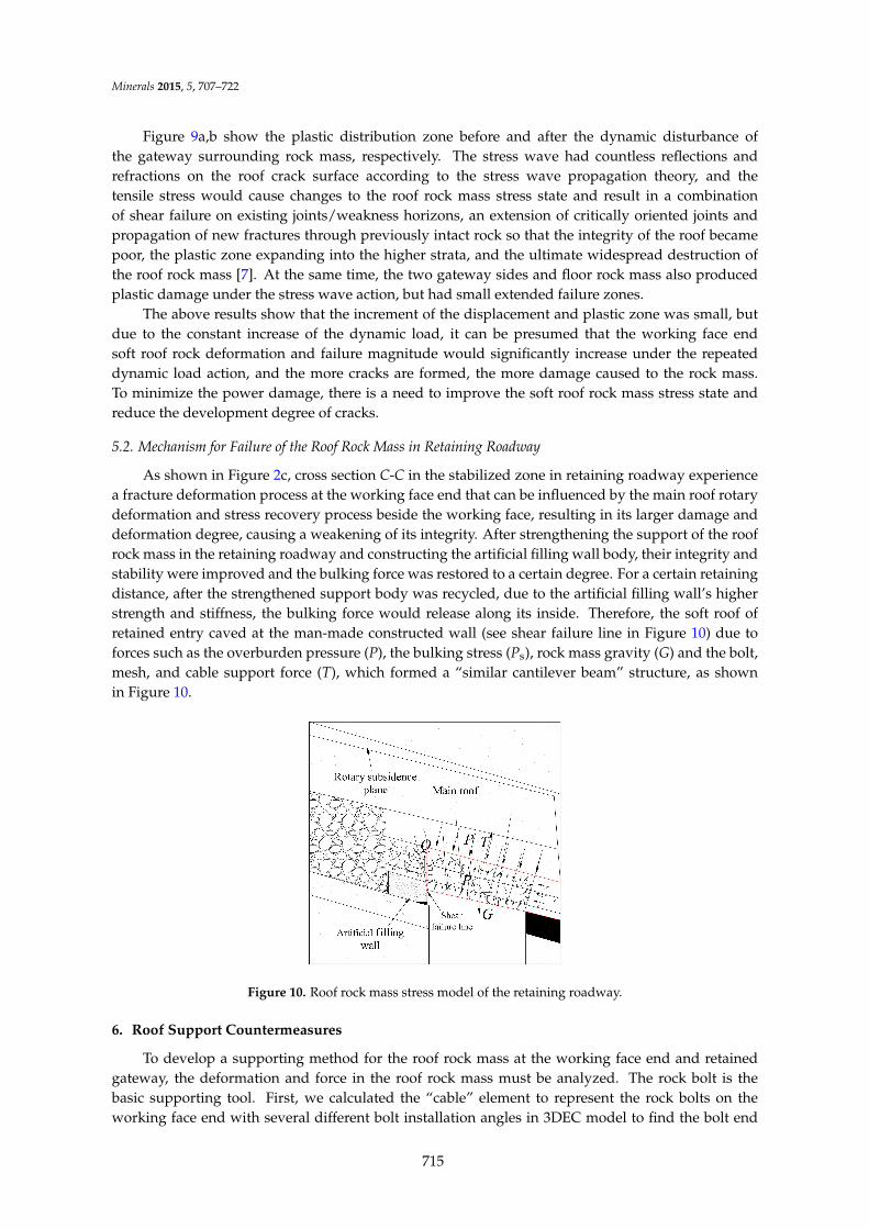
As shown in Figure 2c, cross section C-C in the stabilized zone in retaining roadway experiencea fracture deformation process at the working face end that can be influenced by the main roof rotarydeformation and stress recovery process beside the working face, resulting in its larger damage anddeformation degree, causing a weakening of its integrity. After strengthening the support of the roofrock mass in the retaining roadway and constructing the artificial filling wall body, their integrity andstability were improved and the bulking force was restored to a certain degree. For a certain retainingdistance, after the strengthened support body was recycled, due to the artificial filling wall’s higherstrength and stiffness, the bulking force would release along its inside. Therefore, the soft roof ofretained entry caved at the man-made constructed wall (see shear failure line in Figure 10) due toforces such as the overburden pressure (P), the bulking stress (Ps), rock mass gravity (G) and the bolt,mesh, and cable support force (T), which formed a “similar cantilever beam” structure, as shownin Figure 10.
Minerals 2015, 5, page–page
9
cause changes to the roof rock mass stress state and result in a combination of shear failure on existing joints/weakness horizons, an extension of critically oriented joints and propagation of new fractures through previously intact rock so that the integrity of the roof became poor, the plastic zone expanding into the higher strata, and the ultimate widespread destruction of the roof rock mass [7]. At the same time, the two gateway sides and floor rock mass also produced plastic damage under the stress wave action, but had small extended failure zones.
The above results show that the increment of the displacement and plastic zone was small, but due to the constant increase of the dynamic load, it can be presumed that the working face end soft roof rock deformation and failure magnitude would significantly increase under the repeated dynamic load action, and the more cracks are formed, the more damage caused to the rock mass. To minimize the power damage, there is a need to improve the soft roof rock mass stress state and reduce the development degree of cracks.
5.2. Mechanism for Failure of the Roof Rock Mass in Retaining Roadway
As shown in Figure 2c, cross section C-C in the stabilized zone in retaining roadway experience a fracture deformation process at the working face end that can be influenced by the main roof rotary deformation and stress recovery process beside the working face, resulting in its larger damage and deformation degree, causing a weakening of its integrity. After strengthening the support of the roof rock mass in the retaining roadway and constructing the artificial filling wall body, their integrity and stability were improved and the bulking force was restored to a certain degree. For a certain retaining distance, after the strengthened support body was recycled, due to the artificial filling wall’s higher strength and stiffness, the bulking force would release along its inside. Therefore, the soft roof of retained entry caved at the man-made constructed wall (see shear failure line in Figure 10) due to forces such as the overburden pressure (P), the bulking stress (Ps), rock mass gravity (G) and the bolt, mesh, and cable support force (T), which formed a “similar cantilever beam” structure, as shown in Figure 10.
Figure 10. Roof rock mass stress model of the retaining roadway.
6. Roof Support Countermeasures
To develop a supporting method for the roof rock mass at the working face end and retained gateway, the deformation and force in the roof rock mass must be analyzed. The rock bolt is the basic supporting tool. First, we calculated the “cable” element to represent the rock bolts on the working face end with several different bolt installation angles in 3DEC model to find the bolt end displacement change characteristics. Then, we analyzed the bolt limit equilibrium tension force change features in the retained gateway roof rock mass with the change of the bolt installation angle though the force balance equation.
Figure 10. Roof rock mass stress model of the retaining roadway.
6. Roof Support Countermeasures
To develop a supporting method for the roof rock mass at the working face end and retainedgateway, the deformation and force in the roof rock mass must be analyzed. The rock bolt is thebasic supporting tool. First, we calculated the “cable” element to represent the rock bolts on theworking face end with several different bolt installation angles in 3DEC model to find the bolt end
715

Minerals 2015, 5, 707–722
displacement change characteristics. Then, we analyzed the bolt limit equilibrium tension forcechange features in the retained gateway roof rock mass with the change of the bolt installation anglethough the force balance equation.
6.1. Deformation Analysis of Working Face End Roof
From the soft roof failure process and failure characteristics, the following mechanism for thesoft roof support can be obtained:
(1) Providing the roof rock mass extrusion stress and changing the rock mass stress state toimprove their strength [11]; (2) Preventing cracks from generating and propagating to increaseboth the strength of the affected roof strata and the stiffness of the whole bolted strata to reduceroof deformation and dynamic damage; and (3) Reducing the broken rock mass bulking force andmaintaining the stability of the roadway roof by supporting in time. According to the above pointsand the “bolt extruding reinforcement theory” by pre-tensioned bolts providing a compressive zonein the axial direction [11], the working face end soft roof mechanical structure should be similar tothat in Figure 11 with bolts supporting, so the installation angle is suggested to be 0˝ < α < 90˝.
The distributed axial stress of the pre-tensioned bolts in the extension direction and the lateralstress vertical axial direction can alter the rock stress state, especially for the thin and weak immediateroof conditions [13]. Here, we use the same numerical model and the physical and mechanicalparameters of the rock mass in Figure 4 to analyze the effect of the bolt installation angle α on thestability of the roof rock mass. Bolt installation angles of 50˝, 60˝, 70˝, and 80˝ (in Figure 12) wereapplied in the numerical model and the monitoring bolt end displacement was at y = 45 m with thesame excavation process as shown in Figure 4 conducted, and the results are shown in Figure 13.As actual field bolt installation at an angle α in the mine roof close to 90˝, similar to in Figure 1b, itwas taken as 90˝ to facilitate the analysis, and the results are shown in Section 3.1.
Minerals 2015, 5, page–page
10
6.1. Deformation Analysis of Working Face End Roof
From the soft roof failure process and failure characteristics, the following mechanism for the soft roof support can be obtained:
(1) Providing the roof rock mass extrusion stress and changing the rock mass stress state to improve their strength [11]; (2) Preventing cracks from generating and propagating to increase both the strength of the affected roof strata and the stiffness of the whole bolted strata to reduce roof deformation and dynamic damage; and (3) Reducing the broken rock mass bulking force and maintaining the stability of the roadway roof by supporting in time. According to the above points and the “bolt extruding reinforcement theory” by pre-tensioned bolts providing a compressive zone in the axial direction [11], the working face end soft roof mechanical structure should be similar to that in Figure 11 with bolts supporting, so the installation angle is suggested to be 0° < α < 90°.
The distributed axial stress of the pre-tensioned bolts in the extension direction and the lateral stress vertical axial direction can alter the rock stress state, especially for the thin and weak immediate roof conditions [13]. Here, we use the same numerical model and the physical and mechanical parameters of the rock mass in Figure 4 to analyze the effect of the bolt installation angle α on the stability of the roof rock mass. Bolt installation angles of 50°, 60°, 70°, and 80° (in Figure 12) were applied in the numerical model and the monitoring bolt end displacement was at y = 45 m with the same excavation process as shown in Figure 4 conducted, and the results are shown in Figure 13. As actual field bolt installation at an angle α in the mine roof close to 90°, similar to in Figure 1b, it was taken as 90° to facilitate the analysis, and the results are shown in Section 3.1.
Figure 11. Stress state diagram of soft top supporting effect.
Figure 12. Arrangement diagram of different bolt installation angles: (a) 50°; (b) 60°; (c) 70°; (d) 80°.
Figure 13 shows that:
(1) The monitored displacement had a good regularity and the displacement curve showed a trend of a “concave” type with α increasing as a whole; the vertical displacement of roof was minimal when α = 60°, and the displacement increased when α = 70° and 80°, but it had a smaller increment;
(2) For a certain α, the point displacement increased as the distance to the gob decreased, that is to say, the roof rotated and sank; and
(3) The displacement is larger under the current anchor installation angle (α = 90°) condition; its differences were 155 and 321 mm from the minimum displacement.
Figure 11. Stress state diagram of soft top supporting effect.
Minerals 2015, 5, page–page
10
6.1. Deformation Analysis of Working Face End Roof
From the soft roof failure process and failure characteristics, the following mechanism for the soft roof support can be obtained:
(1) Providing the roof rock mass extrusion stress and changing the rock mass stress state to improve their strength [11]; (2) Preventing cracks from generating and propagating to increase both the strength of the affected roof strata and the stiffness of the whole bolted strata to reduce roof deformation and dynamic damage; and (3) Reducing the broken rock mass bulking force and maintaining the stability of the roadway roof by supporting in time. According to the above points and the “bolt extruding reinforcement theory” by pre-tensioned bolts providing a compressive zone in the axial direction [11], the working face end soft roof mechanical structure should be similar to that in Figure 11 with bolts supporting, so the installation angle is suggested to be 0° < α < 90°.
The distributed axial stress of the pre-tensioned bolts in the extension direction and the lateral stress vertical axial direction can alter the rock stress state, especially for the thin and weak immediate roof conditions [13]. Here, we use the same numerical model and the physical and mechanical parameters of the rock mass in Figure 4 to analyze the effect of the bolt installation angle α on the stability of the roof rock mass. Bolt installation angles of 50°, 60°, 70°, and 80° (in Figure 12) were applied in the numerical model and the monitoring bolt end displacement was at y = 45 m with the same excavation process as shown in Figure 4 conducted, and the results are shown in Figure 13. As actual field bolt installation at an angle α in the mine roof close to 90°, similar to in Figure 1b, it was taken as 90° to facilitate the analysis, and the results are shown in Section 3.1.
Figure 11. Stress state diagram of soft top supporting effect.
Figure 12. Arrangement diagram of different bolt installation angles: (a) 50°; (b) 60°; (c) 70°; (d) 80°.
Figure 13 shows that:
(1) The monitored displacement had a good regularity and the displacement curve showed a trend of a “concave” type with α increasing as a whole; the vertical displacement of roof was minimal when α = 60°, and the displacement increased when α = 70° and 80°, but it had a smaller increment;
(2) For a certain α, the point displacement increased as the distance to the gob decreased, that is to say, the roof rotated and sank; and
(3) The displacement is larger under the current anchor installation angle (α = 90°) condition; its differences were 155 and 321 mm from the minimum displacement.
Figure 12. Arrangement diagram of different bolt installation angles: (a) 50˝; (b) 60˝; (c) 70˝; (d) 80˝.
Figure 13 shows that:
(1) The monitored displacement had a good regularity and the displacement curve showed atrend of a “concave” type with α increasing as a whole; the vertical displacement of roof was
716

Minerals 2015, 5, 707–722
minimal when α = 60˝, and the displacement increased when α = 70˝ and 80˝, but it had asmaller increment;
(2) For a certain α, the point displacement increased as the distance to the gob decreased, that isto say, the roof rotated and sank; and
(3) The displacement is larger under the current anchor installation angle (α = 90˝) condition; itsdifferences were 155 and 321 mm from the minimum displacement.
Minerals 2015, 5, page–page
11
Figure 13. Bolts end displacement.
6.2. Bolt Limit Equilibrium Tension Force
It is known that the working principle of bolts is to maintain the roof rock mass stability in the early stage and to control roof deformation in the later stage. Moreover, carrying out gob-side entry retaining is a systematic project and the roof deformation in the later retaining stage, when maintaining the working face end roof rock mass stability, should be considered. After the construction of the artificial filling wall and recycled reinforcement support body, the roof shear failure (see Figure 2c) is mainly influenced by the bolt-cable-mesh force T, gravity G, shear forces Qa and Qb, and the lateral forces Fa and Fb (reference in Figure 6c), regardless of the overburden pressure because of the roof separation, as shown in Figure 14.
At the moment, the roadway roof rock mass undergoes serious failure and its integrity is poor, so it loses its rigid body properties. Therefore, there is distance h1 between rotating point A and the upper endpoint, so it cannot have a certainty value under the action of torque and 0 ≤ h1 ≤ h.
Figure 14. Stresses-Balanced schematic of roof rock mass.
On the other hand, the roof had been cut along the edge of the gob near the artificial filling wall, so the lateral pressure and shear force can be ignored. In the simplified calculation, it can be set that Fa = 0, Qa = 0. The stress balance relationship in the layer strike direction and vertical layer direction are established, as well as the moment balance relationship established by point A, as shown in Equations (1)–(3), respectively.
bsin cos cos 0T Q Gα + θ− θ = (1)
b bcos sin sin 0T G Q Fα + θ − θ − = (2)
1 2 b 3 0Tl Gl F l− − = (3)
where l1, l2 and l3 are the moment arms of T, G and Fb to point A, respectively, as shown in Equation (4).
Figure 13. Bolts end displacement.
6.2. Bolt Limit Equilibrium Tension Force
It is known that the working principle of bolts is to maintain the roof rock mass stabilityin the early stage and to control roof deformation in the later stage. Moreover, carrying outgob-side entry retaining is a systematic project and the roof deformation in the later retaining stage,when maintaining the working face end roof rock mass stability, should be considered. After theconstruction of the artificial filling wall and recycled reinforcement support body, the roof shearfailure (see Figure 2c) is mainly influenced by the bolt-cable-mesh force T, gravity G, shear forcesQa and Qb, and the lateral forces Fa and Fb (reference in Figure 6c), regardless of the overburdenpressure because of the roof separation, as shown in Figure 14.
At the moment, the roadway roof rock mass undergoes serious failure and its integrity is poor,so it loses its rigid body properties. Therefore, there is distance h1 between rotating point A and theupper endpoint, so it cannot have a certainty value under the action of torque and 0 ď h1 ď h.
Minerals 2015, 5, page–page
11
Figure 13. Bolts end displacement.
6.2. Bolt Limit Equilibrium Tension Force
It is known that the working principle of bolts is to maintain the roof rock mass stability in the early stage and to control roof deformation in the later stage. Moreover, carrying out gob-side entry retaining is a systematic project and the roof deformation in the later retaining stage, when maintaining the working face end roof rock mass stability, should be considered. After the construction of the artificial filling wall and recycled reinforcement support body, the roof shear failure (see Figure 2c) is mainly influenced by the bolt-cable-mesh force T, gravity G, shear forces Qa and Qb, and the lateral forces Fa and Fb (reference in Figure 6c), regardless of the overburden pressure because of the roof separation, as shown in Figure 14.
At the moment, the roadway roof rock mass undergoes serious failure and its integrity is poor, so it loses its rigid body properties. Therefore, there is distance h1 between rotating point A and the upper endpoint, so it cannot have a certainty value under the action of torque and 0 ≤ h1 ≤ h.
Figure 14. Stresses-Balanced schematic of roof rock mass.
On the other hand, the roof had been cut along the edge of the gob near the artificial filling wall, so the lateral pressure and shear force can be ignored. In the simplified calculation, it can be set that Fa = 0, Qa = 0. The stress balance relationship in the layer strike direction and vertical layer direction are established, as well as the moment balance relationship established by point A, as shown in Equations (1)–(3), respectively.
bsin cos cos 0T Q Gα + θ− θ = (1)
b bcos sin sin 0T G Q Fα + θ − θ − = (2)
1 2 b 3 0Tl Gl F l− − = (3)
where l1, l2 and l3 are the moment arms of T, G and Fb to point A, respectively, as shown in Equation (4).
Figure 14. Stresses-Balanced schematic of roof rock mass.
On the other hand, the roof had been cut along the edge of the gob near the artificial fillingwall, so the lateral pressure and shear force can be ignored. In the simplified calculation, it can be
717

Minerals 2015, 5, 707–722
set that Fa = 0, Qa = 0. The stress balance relationship in the layer strike direction and vertical layerdirection are established, as well as the moment balance relationship established by point A, as shownin Equations (1)–(3), respectively.
T sinα`Qb cosθ´ G cosθ “ 0 (1)
T cosα` G sinθ´Qb sinθ´ Fb “ 0 (2)
Tl1 ´ Gl2 ´ Fbl3 “ 0 (3)
where l1, l2 and l3 are the moment arms of T, G and Fb to point A, respectively, as shown inEquation‘(4).
$
’
’
’
&
’
’
’
%
l1 “b
ph1 ` l{2 ¨ tanθq2 ` l2{4¨sin rα` arctanpp2h1 ` l tanθq{lq ´ θs
l2 “ l{2l3 “ ph1 ´ h{2q cosθ
(4)
where l is the roadway width 3.8 m, θ is the coal seam dip angle 16˝, and the gravity G is calculatedaccording to the following Equation:
G “ apn´ 1qb h ρ g cosθ (5)
where a and b are the bolt inter-row spacing, both 800 mm; n is the number of anchor bolts, 6; h is thestudy height of the roof rock mass, 1.5 m; ρ is the average density of the rock mass, 3000 kg/m3; andg is the gravitational acceleration, 10 m/s2.
When T = 6 ˆ 90 kN, G is calculated by Equation (5). Assuming Qb = 0, it can be obtainedthat α = 15˝ and 165˝ according to Equation (1). This means that, if α meets the condition of15˝ ď α ď 165˝, the anchor tension force T is greater than or equal to the roof rock mass gravity in thevertical layer direction. Therefore, the roof can remain stable in this direction.
Furthermore, it can be observed from Equation (2) that α impacts the balance relationship ofEquation (2) and determines the size of the lateral extrusion force Fb. If 0˝ < α < 90˝, it can not onlysatisfy the balance relation but also have a greater Fb value, as does the extrusion stress between thebroken roof rock mass in the layer strike direction.
Substituting Equations (2), (4) and (5) into Equation (3) yields:
T “Gpl2 ` l3 sinθq ´Qbl3 sinθ
l1 ´ l3 cosα(6)
In reality, the lower roof stratum fails more seriously than the upper rock stratum, indicating thatthe roof rotating point A is usually above the roof surface. However, as it is impossible to determinethe true position of the rotating A, we assume that h1 = h, implying that the rotating point A is atthe bottom of study rock body. On the other hand, if the fracture roof rotated, the coal side shearforce would decrease more, so we also assume Qb = 0. Then, substituting each parameter of the minementioned above into Equation (6), produces:
sinpα` 31.1˝q ´ 0.2584 cosα “104.12kN
T(7)
By analyzing Equation (7), the following results are obtained.
(1) If the T value is small, the right value becomes greater than the left maximum value, so it cannotmeet the balance relationship, and the bolts are not able to play their role in supporting. Thisshows that when having a certain bolt installation angle α, there must be some tensile force Tof the bolts to make the right value equal the left value in Equation (7). It also illustrates theimportance of the bolts being pre-tensioned when used in the rock mass.
718

Minerals 2015, 5, 707–722
(2) When α takes the values of 50˝, 60˝, 70˝, 80˝, and 90˝, the relation curve of the bolt tensionT under roof rock mass ultimate stability conditions with an installation angle α is shown inFigure 15a, and the change trend is similar to the curve in Figure 12.
Here, it can be explained that when α is kept constant, the smaller the T value, the smaller the forcerequired for the roof rock mass limit equilibrium under the action of the torque; when the actualbolt tension values remain unchanged, the roof rock mass have a minimum displacement, whichrequires a minimal bolt tension force (Tmin) for limit equilibrium. For example, in Figure 15a, thelargest displacement or the worst stability is when α = 50 and the minimum displacement or the beststability is when α = 70˝ of the roof rock mass. Hence, the roof displacement is proportional to T.Minerals 2015, 5, page–page
13
Figure 15. Relationship of limit equilibrium, anchor tension force, and installation angle, (a) the study condition when θ = 16°; (b) another condition when θ = 0°.
Combining Figures 13 and 15a, it can be observed that when α = 70°, it can provide a failure rock mass with extrusion pressure and alter the stress state, and it can also compress joints and fissures to reduce its opening and the dynamic damage at the same time. Hence, it is advantageous to control the working face end roof and maintain the roof stability in the gob-side entry retaining.
7. Discussion
The thickness of the soft roof stratum in a gently inclined coal seam is small and its strength is low, so mining activities can cause the roof rock mass to serious break and extremely easily cave in, producing a great threat to normal production activities and personnel safety. The selection of a pre-tensioned anchoring technique and bolt arrangement style can improve the bulking roof rock mass stress state by preventing cracks from expanding and reducing the roof separation. To meet the requirements of the retained head entry, a bolt arrangement form is proposed. Furthermore, the application of Equation (6) can be used for the discussion of the supporting measures under similar coal seam geological conditions of, for instance, different coal seam dip angles, gateway widths, and soft roof thicknesses. Because researchers provided more insights into the soft roof failure mechanism of horizontal coal seam by retaining gateway to set α = 90°, thereby assuming the caving height h = 2 m, coal seam dip angle θ = 0°, other conditions remain unchanged as above, thereby determining the proper relationship concerning α and T, as shown in Figure 15b. It shows that T is much large when α = 90° under the high thickness soft roof and horizontal coal seam condition.
On the one hand, the lateral shear forces of Qa and Qb in the theoretical calculation process of Equation (7) are not considered here, but the calculation results and the numerical simulation results are very consistent. Hence, it is feasible to treat the theoretical calculation results as a bolt support reference in the field. On the other hand, only the bolts support is mimicked in the numerical simulation, without incorporating the action of the individual hydraulic props, anchor mesh, and anchor cable, implying that the findings present here are conservative.
In addition, being restricted by current existing technology, it may be difficult to apply this theory practically, as there will be a high degree of drilling difficulty to set the anchor installation angle to α = 70° near the gob edge, as recommended by this paper. However, bolts with a theoretical value α can be installed on the coal side, and for the gob side bolts, α can be set as close as possible to the theoretical value so that they will not be influenced by the roof caving in near the gob, as shown in Figure 2, and to make the most use of the bolts resource by improving their force. The point of the roof failure angle decreased as the horizontal stress level increased, indicating that failure tends to occur around the entry corners when the horizontal stress was low [30]. However, the corner bolts (like e and f in Figure 12) that are installed tilted to the coal side can increase the horizontal stress, so they can prevent shear failure around the entry corners very well.
Figure 15. Relationship of limit equilibrium, anchor tension force, and installation angle, (a) the studycondition when θ = 16˝; (b) another condition when θ = 0˝.
Combining Figures 13 and 15a, it can be observed that when α = 70˝, it can provide a failure rockmass with extrusion pressure and alter the stress state, and it can also compress joints and fissures toreduce its opening and the dynamic damage at the same time. Hence, it is advantageous to controlthe working face end roof and maintain the roof stability in the gob-side entry retaining.
7. Discussion
The thickness of the soft roof stratum in a gently inclined coal seam is small and its strengthis low, so mining activities can cause the roof rock mass to serious break and extremely easily cavein, producing a great threat to normal production activities and personnel safety. The selection ofa pre-tensioned anchoring technique and bolt arrangement style can improve the bulking roof rockmass stress state by preventing cracks from expanding and reducing the roof separation. To meetthe requirements of the retained head entry, a bolt arrangement form is proposed. Furthermore,the application of Equation (6) can be used for the discussion of the supporting measures undersimilar coal seam geological conditions of, for instance, different coal seam dip angles, gatewaywidths, and soft roof thicknesses. Because researchers provided more insights into the soft roof failuremechanism of horizontal coal seam by retaining gateway to set α = 90˝, thereby assuming the cavingheight h = 2 m, coal seam dip angle θ = 0˝, other conditions remain unchanged as above, therebydetermining the proper relationship concerning α and T, as shown in Figure 15b. It shows that T ismuch large when α = 90˝ under the high thickness soft roof and horizontal coal seam condition.
On the one hand, the lateral shear forces of Qa and Qb in the theoretical calculation processof Equation (7) are not considered here, but the calculation results and the numerical simulationresults are very consistent. Hence, it is feasible to treat the theoretical calculation results as a boltsupport reference in the field. On the other hand, only the bolts support is mimicked in the numerical
719

Minerals 2015, 5, 707–722
simulation, without incorporating the action of the individual hydraulic props, anchor mesh, andanchor cable, implying that the findings present here are conservative.
In addition, being restricted by current existing technology, it may be difficult to apply this theorypractically, as there will be a high degree of drilling difficulty to set the anchor installation angle toα = 70˝ near the gob edge, as recommended by this paper. However, bolts with a theoretical valueα can be installed on the coal side, and for the gob side bolts, α can be set as close as possible to thetheoretical value so that they will not be influenced by the roof caving in near the gob, as shown inFigure 2, and to make the most use of the bolts resource by improving their force. The point of theroof failure angle decreased as the horizontal stress level increased, indicating that failure tends tooccur around the entry corners when the horizontal stress was low [30]. However, the corner bolts(like e and f in Figure 12) that are installed tilted to the coal side can increase the horizontal stress, sothey can prevent shear failure around the entry corners very well.
8. Conclusions
This paper analyzed the roof rock mass failure characteristics and their failure mechanism in theworking face end and the gob-side entry retaining, and discussed its support technology accordingto the special gently inclined seam occurrence conditions. The following conclusions were reachedfrom the analysis process:
(1) After the working face advances, it is found that the horizontal stress of the soft rock massat the working face end does not exhibit a large magnitude unloading on the coal wall side,but the horizontal stress momentarily fell, and a tensile stress appeared on the gob side. Thevertical stress in the gateway central dropped significantly, almost down to zero.
(2) The sinking and separation of the soft roof rock mass in the gently inclined coal seam workingface end is affected by the front abutment pressure and the hanging roof on gob side. Theinitiation and propagation of cracks and the fractures of the rock mass are produced by theactions of the lateral stress unloading loose, tensile, and shear stresses in the low layer causedby uneven support and no coupling support and dynamic disturbances.
(3) The roof rock mass failed in shear mode along the inside of man-made constructed wall inthe stability zone of the retained gateway, due to the overburden pressure, bulking force,roof gravity, and combined supporting force. The failed roof forms a “similar cantileverbeam” structure.
(4) The equation of the bolt ultimate equilibrium tension force, a function of the seam inclination,gateway width, soft roof thickness, and bolt installation angle, was established according tothe stress balance analysis of the roof rock.
(5) To prevent the working face end soft roof rock mass from increasing its deformation andbecoming significantly fractured, and also to maintain the gob-side entry retaining roof’sstability, it is suggested that the gateway roof bolt installation angle be 70˝ to provide anextrusion stress, change the rock mass stress state, and improve their strength for betterentry maintenance.
Acknowledgments: The authors gratefully acknowledge funding by National Natural Science FoundationProject of China (51474039, 51404046, 51404168, U1361205), Scientific Research Foundation of State KeyLaboratory of Coal Mine Disaster Dynamics and Control (2011DA105287–ZD201302, 2011DA105287–MS201403),Fundamental Research Funds for the Central Universities (106112015CDJXY240003), and Program Supported bythe Basic Research of Frontier and Application of Chongqing (cstc2015jcy jA90019).
Author Contributions: Hongyun Yang had the original idea for the study and, all co-authors were involved inthe analyses work, sample characterization, writing and revising of all parts of the manuscript.
Conflicts of Interest: The authors declare no conflict of interest.
720

Minerals 2015, 5, 707–722
References
1. Yuan, L. Theory and Practice of Integrated Pillarless Coal Production and Methane Extraction in Multiseams of LowPermeability; China Coal Industry Publishing: Beijing, China, 2008.
2. Zhang, N.; Yuan, L.; Han, C.L.; Xueb, J.; Kan, J. Stability and Deformation of Surrounding Rock in PillarlessGob-Side Entry Retaining. Saf. Sci. 2012, 50, 593–599. [CrossRef]
3. He, T.J. The Breaking Place Prediction of Face End Main Roof Flap Top in the Gob-Side Entry Retaining.J. China Coal Soc. 2000, 25, 28–31.
4. Zhang, G.H. Roof cracking reason analysis about gob-side entry retaining under initiative support. J. ChinaCoal Soc. 2005, 30, 429–432.
5. Gou, P.F.; Zhang, Z.P.; Wei, S.J. Physical Simulation Test of Damage Character of Surrounding Rock underDifferent Levels of the Horizontal Stress. J. China Coal Soc. 2009, 34, 1328–1332.
6. Coggan, J.; Gao, F.Q.; Stead, D.; Elmo, D. Numerical Modelling of the Effects of Weak Immediate RoofLithology on Coal Mine Roadway Stability. Int. J. Coal Geol. 2012, 90, 100–109. [CrossRef]
7. Zhang, D.S.; Mao, X.B.; Ma, W.D. Testing study on deformation Features of Surrounding Rocks of Gob-SideEntry Retaining in Fully-Mechanized Coal Face with Top-Coal Caving. Chin. J. Rock Mech. Eng. 2002, 21,331–334.
8. Xie, W.B. Influence Factors on Stability of Surrounding Rocks of Gob-Side Entry Retaining in Top-CoalCaving Mining Face. Chin. J. Rock Mech. Eng. 2004, 23, 3059–3065.
9. Nemcik, J.; Ma, S.Q.; Aziz, N.; Rena, T.; Geng, X. Numerical Modelling of Failure Propagation in FullyGrouted Rock Bolts Subjected to Tensile Load. Int. J. Rock Mech. Min. Sci. 2014, 71, 293–300. [CrossRef]
10. Ma, S.Q.; Nemcik, J.; Aziz, N. An Analytical Model of Fully Grouted Rock Bolts Subjected to Tensile Load.Constr. Build Mater. 2013, 49, 519–526.
11. Yang, S.S.; Cao, J.P. Evolution Mechanism of Anchoring Stress and Its Correlation with Anchoring Length.J. Min. Saf. Eng. 2010, 27, 2–7.
12. Zheng, X.G.; Zhang, N.; Xue, F. Study on Stress Distribution Law in Anchoring Section of Prestressed Bolt.J. Min. Saf. Eng. 2012, 29, 365–370.
13. Cao, S.G.; Zou, D.J.; Bai, Y.J.; He, P.; Wu, H. Surrounding Rock Control of Mining Roadway in the Thin CoalSeam Group with Short Distance and “Three Soft”. J. Min. Saf. Eng. 2011, 28, 524–529.
14. Fan, K.G.; Jiang, J.Q. Deformation Failure and Non-Harmonious Control Mechanism of Surrounding Rocksof Roadways with Weak Structures. J. China Univ. Min. Technol. 2007, 36, 54–59.
15. Hua, X.Z.; Ma, J.F.; Xu, T.J. Study on Controlling Mechanism of Surrounding Rocks of Gob-Side Entry withCombination of Roadside Reinforced Cable Supporting and Roadway Bolt Supporting and Its Application.Chin. J. Rock Mech. Eng. 2005, 24, 2107–2112.
16. Yan, Y.B.; Shi, J.J.; Jiang, Z.J. Application of Anchor Cable with Bolt and Steel Band Coupling SupportTechnology in Gob-Side Entry Retaining. J. Min. Saf. Eng. 2010, 27, 273–276.
17. Chen, Y.; Bai, J.B.; Wang, X.Y.; Ma, S.-Q.; Xu, Y.; Bi, T.F. Support Technology Research and Application insideRoadway of Gob-Side Entry Retaining. J. China Coal Soc. 2012, 37, 903–910.
18. Jing, L.; Stephansson, O. Fundamentals of Discrete Element Methods for Rock Engineering-Theory andApplications; Elsevier: Amsterdam, The Amsterdam, 2007.
19. Gao, F.Q.; Stead, D. Discrete Element Modelling of Cutter Roof Failure in Coal Mine Roadways. Int. J.Coal Geol. 2013, 116–117, 158–171.
20. Cundall, P.A.; Hart, R.D. Development of Generalized 2–D and 3–D Distinct Element Programs for ModellingJointed Rock; US Army Engineering Waterways Experiment Station: Minneapolis, MN, USA, 1985; SL–85–1.
21. Firpo, G.; Salvini, R.; Francioni, M.; Ranjith, P.G. Use of Digital Terrestrial Photogrammetry in Rocky SlopeStability Analysis by Distinct Elements Numerical Methods. Int. J. Rock Mech. Min. Sci. 2011, 48, 1045–1054.[CrossRef]
22. Gao, F.Q.; Stead, D.; Kang, H.P.; Wu, Y.Z. Discrete Element Modelling of Deformation and Damage of aRoadway Driven along an Unstable Goaf—A Case Study. Int. J. Coal Geol. 2014, 127, 100–110. [CrossRef]
23. Xie, H.P.; Gao, F.; Ju, Y.; Gao, M.Z.; Zhang, R.; Gao, Y.N.; Liu, J.F.; Xie, L.Z. Quantitative definition andinvestigation of deep mining. J. China Coal Soc. 2015, 40, 1–10.
24. Hou, C.J.; Guo, L.S.; Gou, P.F. Rock Bolting for Coal Roadway; China University of Mining and TechnologyPress: Xuzhou, China, 1999; pp. 38–50.
721

Minerals 2015, 5, 707–722
25. Kang, H.P. Study and Application of Complete Rock Bolting Technology to Coal Roadway. Chin. J.Rock Mech. 2005, 24, 161–166.
26. Zhang, Y.Q.; Peng, S.S. Design Considerations for Tensioned Bolts. In Proceedings of the 21stInternational Conference on Ground Control in Mining, West Virginia University, Morgantown, WV, USA,6–8 August 2002; pp. 131–140.
27. Lu, W.B.; Yang, J.H.; Yan, P.; Chen, M.; Zhou, C.; Luo, Y.; Jin, L. Dynamic Response of Rock Mass Inducedby the Transient Release of in-situ Stress. Int. J. Rock Mech. Min. Sci. 2012, 53, 129–141.
28. Felice, J.J.; Beattie, T.A.; Spathis, A.T. Face Velocity Measurements Using a Microwave Radar Technique. InProceedings of the 7th Research Symposium on Explosives and Blasting Technique, Las Vegas, NV, USA,6–7 February 1991; pp. 71–77.
29. Preece, D.S.; Evans, R.; Richards, A.B. Coupled Explosive Gas Flow and Rock Motion Modeling withComparison to Bench Blast Field Data. In Proceeding of the 4th International Symposium on RockFragmentation by Blasting, Vienna, Austria, 5–8 July 1993; pp. 239–246.
30. Peng, S.S. Coal Mine Ground Control, 3rd ed.; China University of Mining and Technology Press:Beijing, China, 2013; pp. 200–203.
© 2015 by the authors; licensee MDPI, Basel, Switzerland. This article is an openaccess article distributed under the terms and conditions of the Creative Commons byAttribution (CC-BY) license (http://creativecommons.org/licenses/by/4.0/).
722