Embed Size (px)
Citation preview
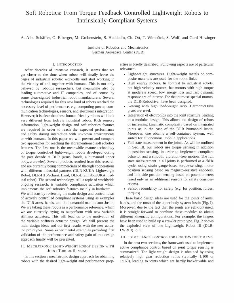
Soft Robotics: From Torque Feedback Controlled LightweightRobots toIntrinsically Compliant Systems
A. Albu-Schaffer, O. Eiberger, M. Grebenstein, S. Haddadin, Ch. Ott, T. Wimbock, S. Wolf, and Gerd Hirzinger
Institute of Robotics and MechatronicsGerman Aerospace Center (DLR)
I. I NTRODUCTION
After decades of intensive research, it seems that weget closer to the time when robots will finally leave thecages of industrial robotic workcells and start working inthe vicinity of and together with humans. This is not onlybelieved by robotics researchers, but meanwhile also byleading automotive and IT companies, and of course bysome clear-sighted industrial robot manufacturers. Severaltechnologies required for this new kind of robots reached thenecessary level of performance, e.g. computing power, com-munication technologies, sensors, and electronics integration.However, it is clear that these human friendly robots will lookvery different from today’s industrial robots. Rich sensoryinformation, light-weight design and soft robotics featuresare required in order to reach the expected performanceand safety during interaction with unknown environmentsor with humans. In this paper we will present and comparetwo approaches for reaching the aforementioned soft roboticsfeatures. The first one is the meanwhile mature technologyof torque controlled light-weight robots developed duringthe past decade at DLR (arms, hands, a humanoid upperbody, a crawler). Several products resulted from this researchand are currently being commercialized through cooperationswith different industrial partners (DLR-KUKA LightweightRobot, DLR-HIT-Schunk Hand, DLR-Brainlab-KUKA med-ical robot). The second technology, still a topic of worldwideongoing research, is variable compliance actuation whichimplements the soft robotics features mainly in hardware.We will start by reviewing the main design and control ideasof actively controlled compliant systems using as examplesthe DLR arms, hands, and the humanoid manipulator Justin.We are taking these robots as a performance reference, whichwe are currently trying to outperform with new variablestiffness actuators. This will lead us to the motivation ofthe variable stiffness actuator design. We will present themain design ideas and our first results with the new actua-tor prototypes. Some experimental examples providing firstvalidation of the performance and safety gain of this designapproach finally will be presented.
II. M ECHATRONIC L IGHT-WEIGHT ROBOT DESIGN WITH
JOINT TORQUESENSING
In this section a mechatronic design approach for obtainingrobots with the desired light-weight and performance prop-
erties is briefly described. Following aspects are of particularrelevance:
• Light-weight structures. Light-weight metals or com-posite materials are used for the robot links.
• High energy motors. In contrast to industrial robots,not high velocity motors, but motors with high torqueat moderate speed, low energy loss and fast dynamicresponse are of interest. For that purpose special motors,the DLR-Robodrive, have been designed.
• Gearing with high load/weight ratio. HarmonicDrivegears are used.
• Integration of electronics into the joint structure, leadingto a modular design. This allows the design of robotsof increasing kinematic complexity based on integratedjoints as in the case of the DLR humanoid Justin.Moreover, one obtains a self-contained system, wellsuited for autonomous, mobile applications.
• Full state measurement in the joints. As will be outlinedin Sec. III, our robots use torque sensing in additionto position sensing, in order to implement compliantbehavior and a smooth, vibration-free motion. The fullstate measurement in all joints is performed at a 3kHzcycle, using strain gauge-based torque-sensing, motorposition sensing based on magneto-resistive encoders,and link-side position sensing based on potentiometers(used only as an additional sensors for safety consider-ations).
• Sensor redundancy for safety (e.g, for position, forces,torques).
These basic design ideas are used for the joints of arms,hands, and the torso of the upper body system Justin (Fig. I).Moreover, due to the fact that the joints are self-contained,it is straight-forward to combine these modules to obtaindifferent kinematic configurations. For example, the fingershave been used to build up a crawler prototype. Fig. 2 showsthe exploded view of one Lightweight Robot III (DLR-LWRIII) joint.
III. C OMPLIANCE CONTROL FORL IGHT-WEIGHT ARMS
In the next two sections, the framework used to implementactive compliance control based on joint torque sensing issummarized. The light-weight design is obtained by usingrelatively high gear reduction ratios (typically 1:100 or1:160), leading to joints which are hardly backdrivable and
1© 2© 3©
4© 5© 6©
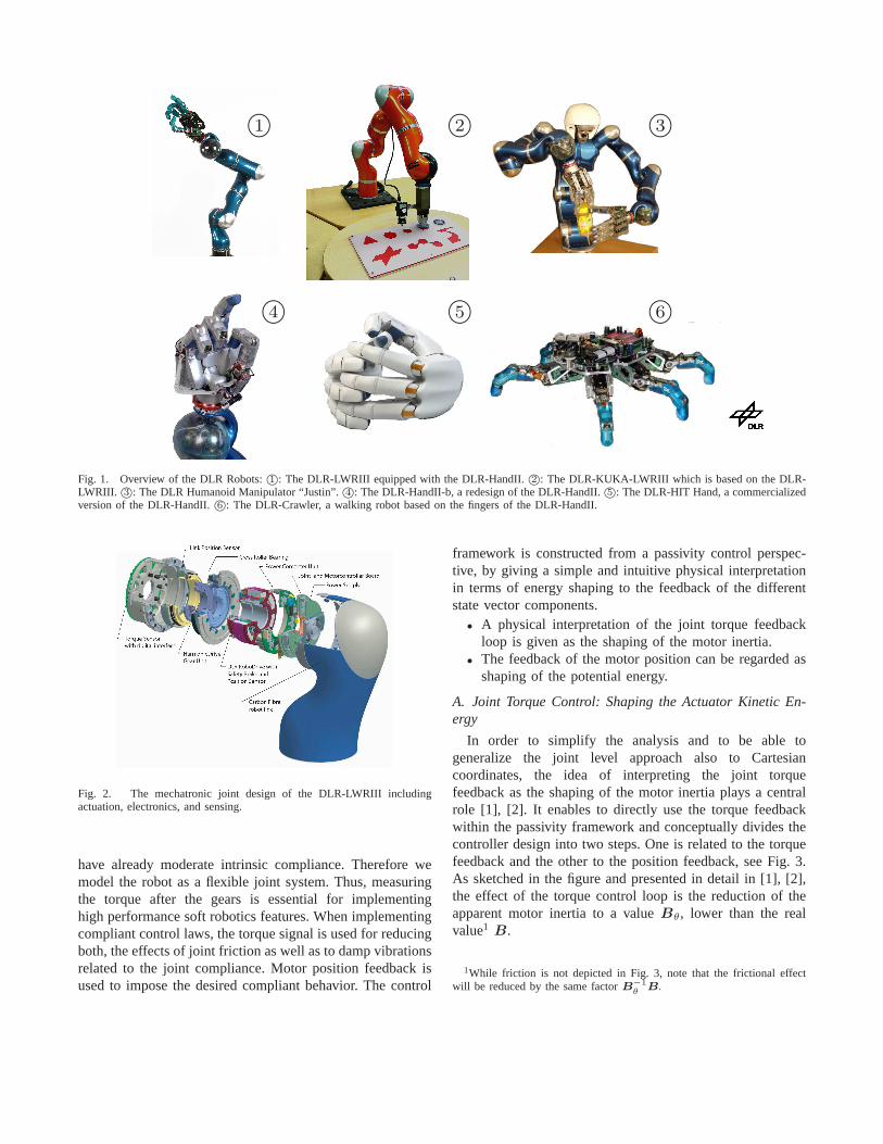
Fig. 1. Overview of the DLR Robots:1©: The DLR-LWRIII equipped with the DLR-HandII.2©: The DLR-KUKA-LWRIII which is based on the DLR-LWRIII. 3©: The DLR Humanoid Manipulator “Justin”.4©: The DLR-HandII-b, a redesign of the DLR-HandII.5©: The DLR-HIT Hand, a commercializedversion of the DLR-HandII.6©: The DLR-Crawler, a walking robot based on the fingers of the DLR-HandII.
Fig. 2. The mechatronic joint design of the DLR-LWRIII includingactuation, electronics, and sensing.
have already moderate intrinsic compliance. Therefore wemodel the robot as a flexible joint system. Thus, measuringthe torque after the gears is essential for implementinghigh performance soft robotics features. When implementingcompliant control laws, the torque signal is used for reducingboth, the effects of joint friction as well as to damp vibrationsrelated to the joint compliance. Motor position feedback isused to impose the desired compliant behavior. The control
framework is constructed from a passivity control perspec-tive, by giving a simple and intuitive physical interpretationin terms of energy shaping to the feedback of the differentstate vector components.
• A physical interpretation of the joint torque feedbackloop is given as the shaping of the motor inertia.
• The feedback of the motor position can be regarded asshaping of the potential energy.
A. Joint Torque Control: Shaping the Actuator Kinetic En-ergy
In order to simplify the analysis and to be able togeneralize the joint level approach also to Cartesiancoordinates, the idea of interpreting the joint torquefeedback as the shaping of the motor inertia plays a centralrole [1], [2]. It enables to directly use the torque feedbackwithin the passivity framework and conceptually divides thecontroller design into two steps. One is related to the torquefeedback and the other to the position feedback, see Fig. 3.As sketched in the figure and presented in detail in [1], [2],the effect of the torque control loop is the reduction of theapparent motor inertia to a valueBθ, lower than the realvalue1 B.
1While friction is not depicted in Fig. 3, note that the frictional effectwill be reduced by the same factorB−1
θB.

τm
u
Bθτ,τ
torquecontrol
rigid robot dynamics
D
K
passive
environment
τa
τext
impedancelaw
g(q)
qdynamics
θ
passive subsystem
q(θ)
Fig. 3. Representation of the compliance controlled robot asa connectionof passive blocks.θ is the motor position andq the link position.B, K andD are the motor inertia, joint stiffness, and damping matrices, respectively.τ is the elastic joint torque,τa the total (elastic and damping) joint torque,τext the external torque, andg the gravity torque.
B. Motor Position Based Feedback: Shaping the PotentialEnergy
Using motor positionθ for control and not the linkposition q is essential for the passivity properties of thecontroller. However, the desired position and stiffness areusually formulated in terms of the link position. For theimpedance controllers of the DLR light-weight robots, theposition feedback has the form
u = −∂VP (q(θ))
∂θ− Dθθ + g(q(θ)) (1)
with u being the input to the torque controller,VP apositive definite potential function, andDθ a positive definitedamping matrix chosen for a well damped transient behavior[3]. This is the classical structure of a compliance controllerfor rigid robots, except for the fact that, instead of the linkpositionq, a position signalq(θ) is used, which isstaticallyequivalentto q, i.e. q(θ) = q if q = θ = 0 and can becomputed numerically2 [1], [2].Since now the position feedback is again only a function ofθ, the passivity of the controlled robot is given with respectto the input-output pair(τ ext, q), see Fig. 3.In order to obtain a joint level impedance controller, onecan simply useVP (q) = 1
2(qd − q)T KJ(qd − q), while for
Cartesian impedance controlVP is defined as function of theCartesian coordinatesx(q) as detailed in section Sec. IV.The external torqueτ ext is then replaced by the externalforce3 F ext. A Lyapunov function for the system is obtainedby summing the kinetic and the gravity-potential energy ofthe rigid part of the robot dynamics with the kinetic energyof the scaled motor inertia and the potential energy of thecontroller [1], [2].
IV. I MPEDANCE CONTROL FORCOMPLEX K INEMATIC
CHAINS
In this section we show how to apply the impedancecontrol concept from the previous section to kinematically
2In practice we often use indeed the trivial approximationq(θ) = θ forapplications in which high position accuracy is not required.
3The relation between the external tip forceF ext and the external jointtorqueτext is τext = J(q)T F ext.
x
x
Hho(q)
Khc,1
Khc,2
Khc,3
Khc,4
Hho,d
Kho
∂Vs
∂q
Fig. 4. DLR Hand II superimposed by the virtual springs definedby thepotential functions in (2) and the virtual object.
more complex robot systems, like artificial hands and an-thropomorphic two-handed manipulator systems.The design of appropriate potential functionsVP (q) is thetopic of this section. Furthermore, we will assume thepotential functionVs of a virtual spatial spring, like e.g. theones designed in [4], [5], [6], as a basic building block. Thispotential functionVs(H1,H2,K) depends on two framesH1 ∈ SE(3) andH2 ∈ SE(3) between which the spring isacting, and also on some configuration-independent internalparametersK, like the stiffness values or the rest length.
A. Artificial Hands
Similar to the DLR light-weight arm, the DLR hand IIis equipped with joint torque sensors in addition to jointposition measurements. Therefore, it is possible to applythe impedance control aspects as presented in the previoussection to our anthropomorphic robot hand. The feedbackof the torque sensors is used to increase the backdrivability,respectively the sensitivity, of the joints. Due to the smalllink masses and the high mechanical joint stiffness, vibrationdamping is not an issue here. Therefore, the approximationq = θ = q can be made. While joint and Cartesianimpedance control are used for power grasp and independentfinger tip motion respectively, the most interesting case froma control point of view is the fine manipulation of a graspedobject since all degrees of freedom of the hand can contributeto its motion. In this case the combined system containingarm, hand, and object represents a parallel robot (Fig. 4).The task coordinates consist of two contributions. On theone hand the Cartesian coordinates of the grasped object,on the other hand the coordinates that are related to internalforces.In [7] we introduced a passivity-based object-level controllerfor a multifingered hand based on a virtual object similar to[8]. In contrast to the IPC [8] the object frame is defineduniquely by thei = 1 . . . N Cartesian fingertip positionspi(q) by an appropriate kinematic relationship. The defini-tion is such that it enables the spanning of the null-spaceof the grasp matrix by internal forces generated by virtual

elastic elements connecting the virtual object frame with thefinger tips (Fig. 4).The definition of a potential functionV (q) to derive anobject level controller is then described by the superpo-sition of two potentials: the potential of a spatial springVs(Hho(q),Hho,d,Kho) between the virtual object frameHho(q) and a virtual equilibrium frameHho,d and a po-tential Vhc(q,Khc) describing theith spring connecting thevirtual object with theith frame of the fingertipsHf,i(q)for i = 1 . . . N that are used to generate internal forces, i. e.
V (q) = Vs(Hho(q),Heq,Kho) + Vhc(q,Khc). (2)
The expressionsKho, Khc contain the stiffness matrix ofthe spatial spring and the coupling spring parameters, re-spectively. The potential for the coupling springs is differentfrom the potentials for spatial springs and is chosen to bespherical for each fingertipi [7]:
Vhc(q,Khc) =1
2
N∑
i=1
Khc,i [‖∆pi(q)‖ − li,d]2, (3)
with ∆pi(q) = pi(q) − pho(q) being the distance from theposition of the fingertip framei to the virtual object frameposition pho, and Khc,i > 0 the corresponding couplingstiffness.
B. Employing Impedance Control for Two-Handed Manipu-lation
A natural extension of the impedance control approachesfor the arms and hands allows to formulate intuitive compli-ance behaviors also for more complex anthropomorphic ma-nipulators like the humanoid manipulator ”Justin” (Fig. I-3©).This system was built at DLR as a testbed for studying two-handed manipulation tasks. It consists of two four-fingeredartificial hands, two lightweight arms, and a sensor headmounted on a movable torso including the neck. Overall,”Justin” has 43 degrees of freedom.
Let us first consider the problem of controlling two arms.The end-effector frames of the right and left arm willbe denoted asHr(q) and H l(q), respectively. Similar tomultifingered hands, the compliance control of two arms hasto handle the interaction forces between the two arms as wellas the forces which the two arms exert cooperatively on theenvironment. The implementation, however, is even simplerin this case and can be done by combining two spatialsprings. One spatial spring defines the relative compliancebetween the arms and can be described in a straight-forwardway by the potential functionVs(Hr(q),H l(q),Kc). Forimplementing the cooperative action of the two arms it isuseful to rely on a virtual object frameHo(Hr(q),H l(q))depending on the two end effector frames of the right and leftarm. This object frame describes a relevant pose in betweenthe arms (usually just the mean between the pose of theright and left arm) and thus represents the pose of a graspedobject. This virtual object is then connected via a spatialspringKo to a virtual equilibrium poseHo,d. In combinationwith the coupling stiffness, one thus can intuitively define
an impedance behavior which is useful for grasping largeobjects with two arms. The resulting potential function isgiven by
VP (q) = Vs(Ho(Hr(q),H l(q)),Ho,d,Ko) +
Vs(Hr(q),H l(q),Kc) . (4)
In case of a two-handed system such a compliance behaviorcan easily be combined with the object level compliancepotentials designed for artificial hands. Therefore, the vir-tual visco-elastic springs are attached now to the virtualobject framesHr,o(q) and H l,o(q) of the hands insteadof attaching them directly to the end-effectors of the arms(Fig. 5). In combination with the interconnection potentialsVhcr(q,Khcr) and Vhcl(q,Khcl) for the right and left handthe complete potential function is now given by
VP (q) = Vs(Ho(Hr,o(q),H l,o(q)),Ho,d,Ko) +
Vs(Hr,o(q),H l,o(q),Kc) +
Vhcr(q,Khcr) + Vhcl(q,Khcl) . (5)
Notice that all spatial springs generate joint torques forthe arms, hands, as well as for the torso by computingthe total derivative of the potential function with respectto the generalized coordinates of the complete mechanism(c.f. (1)). The presented control approach results in a passiveclosed loop system by design and it is therefore related toother intuitive passivity based control approaches like theIPC [8]. Moreover, the chosen set of virtual spatial springsallows for a conceptually simple physical interpretation andconsequently for an intuitive parametrization in any higher-level planning stage.
Ho(q)
Ho,d
Kc
Ko
Fig. 5. Two-hand impedance behavior by combining the object levelimpedances of the hands and the arms.
V. A DJUSTING THEMECHANICAL COMPLIANCE:MOTIVATION OF THE VARIABLE STIFFNESSACTUATOR
DESIGN
A. From Actively Controlled to Passive Compliance
The paradigm of torque controlled light-weight robots waspresented in some detail up to now. Various robot examplesand the underlying control concepts were introduced. Based
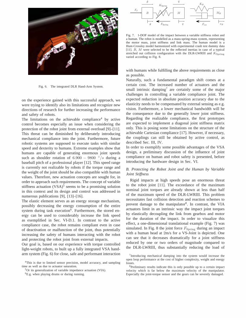
Fig. 6. The integrated DLR Hand-Arm System.
on the experience gained with this successful approach, wewere trying to identify also its limitations and recognize newdirections of research for further increasing the performanceand safety of robots.The limitations on the achievable compliance4 by activecontrol becomes especially an issue when considering theprotection of the robot joint from external overload [9]–[11].This threat can be diminished by deliberately introducingmechanical compliance into the joint. Furthermore, futurerobotic systems are supposed to execute tasks with similarspeed and dexterity to humans. Extreme examples show thathumans are capable of generating enormous joint speedssuch as shoulder rotation of6.900 − 9800 ◦/s during abaseball pitch of a professional player [12]. This speed rangeis currently not realizable by robots if the torque range andthe weight of the joint should be also compatible with humanvalues. Therefore, new actuation concepts are sought for, inorder to approach such requirements. The concept of variablestiffness actuation (VSA)5 seems to be a promising solutionin this context and its design and control was addressed innumerous publications [9], [13]–[16].The elastic element serves as an energy storage mechanism,possibly decreasing the energy consumption of the entiresystem during task execution6. Furthermore, the stored en-ergy can be used to considerably increase the link speedas exemplified in Sec. VI-D.1. In contrast to the activecompliance case, the robot remains compliant even in caseof deactivation or malfunction of the joint, thus potentiallyincreasing the safety of humans interacting with the robotand protecting the robot joint from external impacts.Our goal is, based on our experience with torque controlledlight-weight robots, to built up a fully integrated VSA hand-arm system (Fig. 6) for close, safe and performant interaction
4This is due to limited sensor precision, model accuracy, and samplingtime as well as due to actuator saturation.
5Or its generalization of variable impedance actuation (VIA).6E.g. when playing drums or during running.
FSpring
MH
KH
xHFext
B M
KSpring
θ q
Fd
θ q
Fig. 7. 1-DOF model of the impact between a variable stiffness robot anda human. The robot is modelled as a mass-spring-mass system, representingthe motor mass, joint stiffness and link mass. The human model is aHunt-Crossley model harmonized with experimental crash test dummy data[11]. B, M were selected to be the reflected inertias in case of a typicalstretched out collision configuration with the DLR-LWRIII and KSpring
varied according to Fig. 8.
with humans while fulfilling the above requirements as closeas possible.Naturally, such a fundamental paradigm shift comes at acertain cost. The increased number of actuators and thesmall intrinsic damping7 are certainly some of the majorchallenges in controlling a variable compliance joint. Theexpected reduction in absolute position accuracy due to theelasticity needs to be compensated by external sensing as e.g.vision. Furthermore, a lower mechanical bandwidth will bethe consequence due to the generally lower joint stiffness.Regarding the realizable compliance, the first prototypesare expected to implement a diagonal joint stiffness matrixonly. This is posing some limitations on the structure of theachievable Cartesian compliance [17]. However, if necessary,the couplings can still be obtained by active control, asdescribed Sec. III, IV.In order to exemplify some possible advantages of the VSAdesign, a preliminary discussion of the influence of jointcompliance on human and robot safety is presented, beforeintroducing the hardware design in Sec. VI.
B. Protecting the Robot Joint and the Human by VariableJoint Stiffness
Rigid impacts at high speeds pose an enormous threatto the robot joint [11]. The exceedance of the maximumnominal joint torques are already shown at less than halfof the maximum speed of the DLR-LWRIII. This problemnecessitates fast collision detection and reaction schemes toprevent damage to the manipulator8. In contrast, the VIAactuators limit in an intrinsic way the impact joint torquesby elastically decoupling the link from gearbox and motorfor the duration of the impact. In order to visualize thiseffect, a one-dimensional translational example (Fig. 7) wassimulated. In Fig. 8 the joint forceFSpring during an impactwith a human head at2m/s for a VS-Joint is depicted. Onecan see that it decreases dramatically for a joint stiffnessreduced by one or two orders of magnitude compared tothe DLR-LWRIII, thus substantially reducing the load of
7Introducing mechanical damping into the system would increase theopen loop performance at the cost of higher complexity, weightand energylosses.
8Preliminary results indicate this is only possible up to a certain impactvelocity which is far below the maximum velocity of the manipulator.Especially the joint-torque sensor and the gears can be severely damaged.

0 0.1 0.2 0.3 0.4 0.50
1000
2000
3000
time t[s]
0
100
200
300
400
0 0.1 0.2 0.3 0.4 0.50
1000
2000
3000
time t[s]
0
100
200
300
400
0 0.1 0.2 0.3 0.4 0.50
1000
2000
3000
time t[s]
0
100
200
300
400
KSpring = KLWRIII
KSpring = 0.1KLWRIII
KSpring = 0.01KLWRIII
HIC = 28.8
HIC = 28.8
HIC = 28.8
Fext
FSpring
Fext
FSpring
Fext
FSpring
Fext[N
]F
ext[N
]F
ext[N
]
FSpri
ng[N
]F
Spri
ng[N
]F
Spri
ng[N
]
Fig. 8. Effect of joint stiffness reduction on impact force, HIC and springforce during an impact with the human head at2m/s impact velocity. Thespring force decreases in magnitude and increases in duration when loweringthe spring stiffness. The joint stiffnessKSpring was chosen to beKLWRIII,0.1KLWRIII and0.01KLWRIII, i.e. 100%, 10%, and1% of the reflectedDLR-LWRIII joint stiffness.
xRxR
+xd
Blade
Fig. 9. The DLR-LWRIII equipped with a knife moves along a desiredtrajectory. The penetrated material is a silicone block. This experimentshows the benefit of intrinsic or controlled joint elasticity during impactswith sharp tools. The goal positionxd was≈ 7cm inside the silicone block.
the joint. First experimental results confirming the abovestatements are shown in Sec. VI-D.3.The possible injury of the human during such rigid impactsis discussed in detail in [11], [18]. It is shown there thatthe impact forces (which are related to the kinetic energy)and thus the potential injury of a human do not dependon the joint stiffness already for link inertias and jointstiffness similar to the ones of the DLR-LWRIII. In Fig. 8the Head injury Criterion (HIC) and the impact forcesFext
are depicted, showing that even with reduced joint stiffnessthey basically stay the same. This can be explained by thefact that rigid impacts are practically over before the jointforce starts rising. In other words it is only the link inertiainvolved in such hard and rigid impacts.
A case for which compliance of the robot does reduce theinjury risk for humans is given by impacts with sharp toolsat moderate velocity. This is exemplified by the experimentfrom Fig 9, in which the DLR-LWR holding a knife movesalong a desired trajectory in position or joint impedance con-trolled mode, penetrating a silicone block. It shows in Fig.10that with very low joint stiffness the force and penetrationdepth increase much slower. For this particular trajectoryone
0 0.5 1 1.5 20
20
40
60
80
100
Contact force @ 0.1m/s
time t[s]
For
ce[N
]
Pos. contr.Imp. contr.
0 0.5 1 1.5 20
0.005
0.01
0.015
0.02
0.025
0.03Penetration depth @ 0.1m/s
time t[s]
∆x
[m]
Pos. contr.Imp. contr.
0 0.1 0.2 0.3 0.4 0.50
20
40
60
80
100
Contact force @ 0.45m/s
time t[s]
For
ce[N
]
Pos. contr.Imp. contr.
0 0.1 0.2 0.3 0.4 0.50
0.005
0.01
0.015
0.02
0.025
0.03Penetration depth @ 0.45m/s
time t[s]
∆x
[m]
Pos. contr.Imp. contr.
Fig. 10. Contact force and penetration depth for two different Cartesianvelocities of0.1m/s and0.45m/s. Clearly, the benefit of the reduction ofjoint stiffness is apparent. The force level can be decreased even belowlevels which would potentially harm a human, whereas in position controlthe force significantly exceeds this threshold. The goal position xd was≈ 7cm inside the silicone block.
presumably could prevent damaging the human skin9.Apart from these benefits, the problem of impacting in apretensioned state or at very high joint velocities causedby striking out is of major focus for future research. Thisproblem is especially important in the context discussedin Sec. VI-D.1 which shows a vast performance increaseconcerning link velocity by using the stored potential energyof the joint spring to further accelerate the link inertia.While these two examples are intended to illustrate thebenefit of VSA design from the robot safety and performancepoint of view, the next section will introduce the DLR-VSA design and present some experimental evidence ofthe performance increase and robot protection. Increasinghuman safety by VIA design is also a major issue whichwill constitute the topic of a separate publication.
VI. N EW HARDWARE DESIGN CONCEPTS
The simplest intrinsically compliant joint realization has afixed spring behavior, usually with a constant or progressivestiffness characteristic. This results in a significant loss oflink motion bandwidth. To reduce this effect the stiffness ofthe joint has to be adaptable to the desired task, requiring asecond actuator. Several design approaches realizing roboticjoints with variable mechanical stiffness are described intheliterature [9], [13]–[16].The biologically motivated concept of antagonistic actuationcan be found already in some robotic systems [20], [14],[21]. In these realizations two opposing actuators of similarsize, each in combination with a series elastic element drive
9Already contact forces of< 80N are enough to penetrate the humanskin and cause further injury with a knife in case of stabbing[18].However, with appropriate collision detection strategies, we confirmed inswine experiments that the DLR-LWR can avoid injuries with such sharptools as knifes up to certain velocity [19]. The additional compliance ofthe actuator will increase the time available to react thus enabling highermaximal velocities.
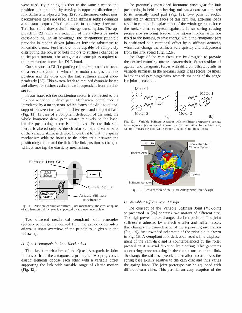
were used. By running together in the same direction theposition is altered and by moving in opposing direction thelink stiffness is adjusted (Fig. 12a). Furthermore, unlessnon-backdrivable gears are used, a high stiffness setting demandsa constant torque of both actuators in opposing directions.This has some drawbacks in energy consumption. The ap-proach in [22] aims at a reduction of these effects by motorcross-coupling. As an advantage, the antagonistic principleprovides in tendon driven joints an intrinsic robustness tokinematic errors. Furthermore, it is capable of completelydistributing the power of both motors to stiffness changes orto the joint motion. The antagonistic principle is applied tothe new tendon controlled DLR hand.
Current work at DLR regarding robot arm joints is focusedon a second option, in which one motor changes the linkposition and the other one the link stiffness almost inde-pendently [23]. This system leads to reduced dynamic lossesand allows for stiffness adjustment independent from the linkspeed.
In our approach the positioning motor is connected to thelink via a harmonic drive gear. Mechanical compliance isintroduced by a mechanism, which forms a flexible rotationalsupport between the harmonic drive gear and the joint base(Fig. 11). In case of a compliant deflection of the joint, thewhole harmonic drive gear rotates relatively to the base,but the positioning motor is not moved. So the link sideinertia is altered only by the circular spline and some partsof the variable stiffness device. In contrast to that, the springmechanism adds no inertia to the drive train between thepositioning motor and the link. The link position is changedwithout moving the elasticity mechanism.
Harmonic Drive Gear
Circular Spline
Variable StiffnessMechanism
Fig. 11. Principle of variable stiffness joint mechanics. The circular splineof the harmonic drive gear is supported by the new mechanism.
Two different mechanical compliant joint principles(patents pending) are derived from the previous consider-ations. A short overview of the principles is given in thefollowing.
A. Quasi Antagonistic Joint Mechanism
The elastic mechanism of the Quasi Antagonistic Jointis derived from the antagonistic principle: Two progressiveelastic elements oppose each other with a variable offsetsupporting the link with variable range of elastic motion(Fig. 12).
The previously mentioned harmonic drive gear for linkpositioning is held in a bearing and has a cam bar attachedto its normally fixed part (Fig. 13). Two pairs of rockerarms act on different faces of this cam bar. External loadsresult in rotational displacement of the whole gear and forcethe rocker arms to spread against a linear spring causingprogressive restoring torque. The agonist rocker arms arefixed to the housing to save energy, while the antagonist partis positioned at a rotational offset by a stiffness actuator,which can change the stiffness very quickly and independentfrom the link speed (Fig. 12.b).
The shape of the cam faces can be designed to providethe desired restoring torque characteristic. Superposition ofagonist and antagonist forces with different offsets results invariable stiffness. In the nominal range it has (close to) linearbehavior and gets progressive towards the ends of the rangefor joint protection.
(a)Motor 2
Motor 1
(b)
Motor 1
Motor 2
Fig. 12. Variable Stiffness Actuator with nonlinear progressive springsin antagonistic (a) and quasi antagonistic (b) realization. In the later case,Motor 1 moves the joint while Motor 2 is adjusting the stiffness.
Cam Bar
Rocker Arm
Spring
Stiffness Actuator
Connection toCircular Spline
Fig. 13. Cross section of the Quasi Antagonistic Joint design.
B. Variable Stiffness Joint Design
The concept of the Variable Stiffness Joint (VS-Joint)as presented in [24] contains two motors of different size.The high power motor changes the link position. The jointstiffness is adjusted by a much smaller and lighter motor,that changes the characteristic of the supporting mechanism(Fig. 14). An unwinded schematic of the principle is shownin Fig. 15. A compliant link deflection results in a displace-ment of the cam disk and is counterbalanced by the rollerpressed on it in axial direction by a spring. This generatesa centering force resulting in the output torque of the link.To change the stiffness preset, the smaller motor moves thespring base axially relative to the cam disk and thus variesthe spring force. The joint prototype can be equipped withdifferent cam disks. This permits an easy adaption of the

passive joint behavior to the desired application by designingthe torque/deflection characteristic of the joint.
Cam Disk
Roller
Connection toLinear Bearing
Roller Slider
Spring Base Slider
Axis of Rotation
Fig. 14. VS-Joint mechanism. The link axis is in the vertical direction.The cam disk rotates on a compliant link deflection.
C. Control of Variable Impedance Actuators
Regarding the control of VIA, the literature mostly dealswith the problem of adjusting stiffness and position of theactuator in a decoupled manner, by controlling the positionor the torque of the two motors of the joint [13], [15], [16].Moreover, in case of VSA structures with many dof and cableactuation, the decoupling of the tendon control is treated [25],[26].Our approach to the control of the VSA arms is to extend thepassivity based control framework developed for the torquecontrolled light-weight robots to the VSA case. Some par-ticular aspects compared to the controllers from Sec. III, IVare summarized below:
• Due to the high compliance of the joint, a separatetorque sensor is not required any more, the torque canbe well estimated based on the motor and link position[24].
• An active compliance control will be used only forstiffness components which cannot be realized by themechanical springs. Examples are zero stiffness or thejoint coupling stiffness needed by arbitrary Cartesianstiffness matrices [17].
• The joints have very low intrinsic damping. While thisis useful for cyclic movements, involving energy storage(e.g. for running), the damping of the arm for fast, finepositioning tasks has to be realized by control. This is
(a)
Cam Disk
Linear Bearing
Roller
(b)
Roller Positionof Undeflected Link
α
Deflection
Fτ
Fig. 15. Unwinded schematic of the VS-Joint principle in centered (a)and deflected (b) position. A deflection of the link results ina horizontalmovement of the cam disk and a vertical displacement of the roller. Thespring force generates a centering torque on the cam disk.
0 0.1 0.2 0.3 0.4 0.5 0.6 0.7 0.8 0.9 1−0.2
0
0.2
0.4
0.6
0.8
1
1.2
link
velo
city
[rad
/s]
time [s]
10% of max. stiffness100% of max. stiffness
0 0.1 0.2 0.3 0.4 0.5 0.6 0.7 0.8 0.9 1−18
−16
−14
−12
−10
−8
−6
−4
−2
0
2
join
t tor
que
[Nm
]
time [s]
10% of max. stiffness100% of max. stiffness
Fig. 16. Motion on a trajectory with rectangular velocity profile for smalland maximal stiffness. A critically damped velocity step response can beachieved independent from the stiffness and inertia value (upper). The effectof vibration damping is clearly observed in the torque signal(lower).
a challenging task, regarding the strong variation of theinertia and the stiffness. Fig. 16 shows the performanceof the positioning for a very low as well as for a veryhigh stiffness preset of the VS-Joint.
• Absolute accuracy of fine manipulation has to be real-ized using additional external sensing at the tip.
• The antagonistically tendon-driven joints of the hand(Fig. 6) require the extension to handle nonlinear cou-pled joints based on the tendon coupling matrix.
• The pulling constraint of the tendons has to be fulfilledstrictly. Decoupling algorithms will be used to ensurethe realization of the passive joint stiffness while theactive joint stiffness can be varied over a large domain.Furthermore, a quasi-static effective joint stiffness canbe given as a setpoint.
D. Performance Validation
Along with the activity regarding the control of the joint,first experiments for validating the increase in performancewere done.
1) Throwing: The application of throwing a ball is a goodexample to show the performance enhancement gained by theVS-Joint in terms of maximal velocity. For throwing a ballas far as possible, it has to be accelerated to the maximumachievable velocity and released at an angle of45◦. The linkvelocity of a stiff link corresponds to the velocity of thedriving motor. In a flexible joint the potential energy storedin the system can be used to accelerate the link relativelyto the driving motor. Additional energy can be inserted bythe stiffness adjuster of the variable stiffness joint to gain an
0 0.05 0.1 0.15 0.2 0.25 0.3 0.35 0.4 0.45 0.5
−70
−60
−50
−40
−30
Throwing Trajectory
Time (s)Position
(deg
)
Desired Motor PositionMotor PositionLink Position
0 0.05 0.1 0.15 0.2 0.25 0.3 0.35 0.4 0.45 0.550
60
70
80
90
100Stiffness Actuator Position
Time (s)
Position
(%)
0 0.05 0.1 0.15 0.2 0.25 0.3 0.35 0.4 0.45 0.5−400
−200
0
200
400
600Throwing Velocity
Time (s)
Vel
oci
ty(d
eg/s)
Motor VelocityLink Velocity
(a)
(b)
(c)
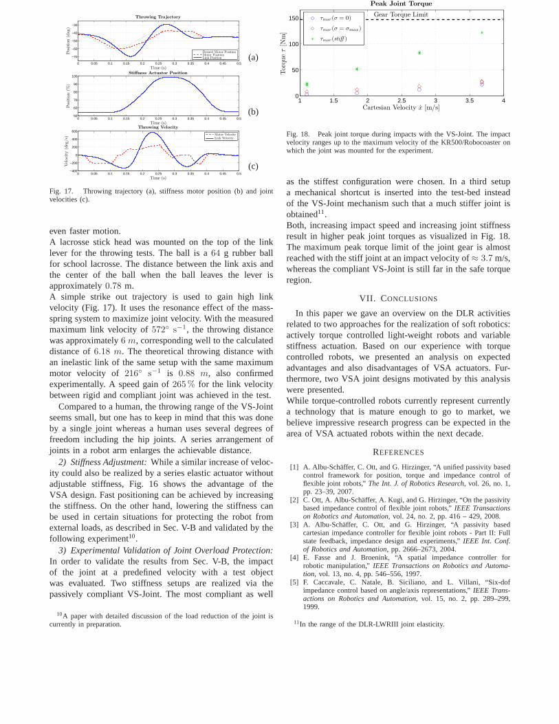
Fig. 17. Throwing trajectory (a), stiffness motor position (b) and jointvelocities (c).
even faster motion.A lacrosse stick head was mounted on the top of the linklever for the throwing tests. The ball is a64 g rubber ballfor school lacrosse. The distance between the link axis andthe center of the ball when the ball leaves the lever isapproximately0.78 m.A simple strike out trajectory is used to gain high linkvelocity (Fig. 17). It uses the resonance effect of the mass-spring system to maximize joint velocity. With the measuredmaximum link velocity of572◦ s−1, the throwing distancewas approximately6 m, corresponding well to the calculateddistance of6.18 m. The theoretical throwing distance withan inelastic link of the same setup with the same maximummotor velocity of 216◦ s−1 is 0.88 m, also confirmedexperimentally. A speed gain of265% for the link velocitybetween rigid and compliant joint was achieved in the test.
Compared to a human, the throwing range of the VS-Jointseems small, but one has to keep in mind that this was doneby a single joint whereas a human uses several degrees offreedom including the hip joints. A series arrangement ofjoints in a robot arm enlarges the achievable distance.
2) Stiffness Adjustment:While a similar increase of veloc-ity could also be realized by a series elastic actuator withoutadjustable stiffness, Fig. 16 shows the advantage of theVSA design. Fast positioning can be achieved by increasingthe stiffness. On the other hand, lowering the stiffness canbe used in certain situations for protecting the robot fromexternal loads, as described in Sec. V-B and validated by thefollowing experiment10.
3) Experimental Validation of Joint Overload Protection:In order to validate the results from Sec. V-B, the impactof the joint at a predefined velocity with a test objectwas evaluated. Two stiffness setups are realized via thepassively compliant VS-Joint. The most compliant as well
10A paper with detailed discussion of the load reduction of thejoint iscurrently in preparation.
1 1.5 2 2.5 3 3.5 40
50
100
150
Peak Joint Torque
Cartesian Velocity x [m/s]
Torq
ue
τ[N
m]
Gear Torque Limitτmsr(σ = 0)
τmsr(σ = σmax)
τmsr(stiff )
Fig. 18. Peak joint torque during impacts with the VS-Joint. The impactvelocity ranges up to the maximum velocity of the KR500/Robocoaster onwhich the joint was mounted for the experiment.
as the stiffest configuration were chosen. In a third setupa mechanical shortcut is inserted into the test-bed insteadof the VS-Joint mechanism such that a much stiffer joint isobtained11.Both, increasing impact speed and increasing joint stiffnessresult in higher peak joint torques as visualized in Fig. 18.The maximum peak torque limit of the joint gear is almostreached with the stiff joint at an impact velocity of≈ 3.7 m/s,whereas the compliant VS-Joint is still far in the safe torqueregion.
VII. C ONCLUSIONS
In this paper we gave an overview on the DLR activitiesrelated to two approaches for the realization of soft robotics:actively torque controlled light-weight robots and variablestiffness actuation. Based on our experience with torquecontrolled robots, we presented an analysis on expectedadvantages and also disadvantages of VSA actuators. Fur-thermore, two VSA joint designs motivated by this analysiswere presented.While torque-controlled robots currently represent currentlya technology that is mature enough to go to market, webelieve impressive research progress can be expected in thearea of VSA actuated robots within the next decade.
REFERENCES
[1] A. Albu-Schaffer, C. Ott, and G. Hirzinger, “A unified passivity basedcontrol framework for position, torque and impedance controlofflexible joint robots,”The Int. J. of Robotics Research, vol. 26, no. 1,pp. 23–39, 2007.
[2] C. Ott, A. Albu-Schaffer, A. Kugi, and G. Hirzinger, “On the passivitybased impedance control of flexible joint robots,”IEEE Transactionson Robotics and Automation, vol. 24, no. 2, pp. 416 – 429, 2008.
[3] A. Albu-Schaffer, C. Ott, and G. Hirzinger, “A passivity basedcartesian impedance controller for flexible joint robots - Part II: Fullstate feedback, impedance design and experiments,”IEEE Int. Conf.of Robotics and Automation, pp. 2666–2673, 2004.
[4] E. Fasse and J. Broenink, “A spatial impedance controllerforrobotic manipulation,”IEEE Transactions on Robotics and Automa-tion, vol. 13, no. 4, pp. 546–556, 1997.
[5] F. Caccavale, C. Natale, B. Siciliano, and L. Villani, “Six-dofimpedance control based on angle/axis representations,”IEEE Trans-actions on Robotics and Automation, vol. 15, no. 2, pp. 289–299,1999.
11In the range of the DLR-LWRIII joint elasticity.

[6] S. Stramigioli and V. Duindam, “Variable spatial springs for robot con-trol applications,” inIEEE/RSJ International Conference on IntelligentRobots and Systems, 2001, pp. 1906–1911.
[7] T. Wimbock, Ch. Ott, and G. Hirzinger, “Passivity-based object-level impedance control for a multifingered hand,” inIEEE/RSJInternational Conference on Intelligent Robots and Systems, 2006, pp.4621–4627.
[8] S. Stramigioli,Modeling and IPC Control of Interactive MechanicalSystems: A Coordinate-free Approach, ser. Lecture Notes in Controland Information Sciences. Springer-Verlag, 2001, vol. 266.
[9] T. Morita, H. Iwata, and S. Sugano, “Development of human symbioticrobot: Wendy.”IEEE Int. Conf. of Robotics and Automation, pp. 3183–3188, 1999.
[10] S. Haddadin, T. Laue, U. Frese, and G. Hirzinger, “Foul 2050:Thoughts on physical interaction in human-robot soccer,” inIEEE/RSJ International Conference on Intelligent Robots and Systems(IROS2007), San Diego, USA, 2007, pp. 3243–3250.
[11] S. Haddadin, A. Albu-Schaffer, and G. Hirzinger, “Safety Evaluationof Physical Human-Robot Interaction via Crash-Testing,”Robotics:Science and Systems Conference (RSS2007), Atlanta, USA, download:http://www.roboticsproceedings.org/rss03/p28.html, 2007.
[12] I. P. Herman,Physics of the Human Body. Springer Verlag, 2007.[13] A. Bicchi and G. Tonietti, “Fast and Soft Arm Tactics: Dealing with the
Safety-Performance Trade-Off in Robot Arms Design and Control,”IEEE Robotics and Automation Mag., vol. 11, pp. 22–33, 2004.
[14] S. A. Migliore, E. A. Brown, and S. P. DeWeerth, “BiologicallyInspired Joint Stiffness Control,” inIEEE Int. Conf. on Robotics andAutomation (ICRA2005), Barcelona, Spain, 2005.
[15] G. Palli, C. Melchiorri, T. Wimboeck, M. Grebenstein, andG. Hirzinger, “Feedback linearization and simultaneous stiffness-position control of robots with antagonistic actuated joints,” in IEEEInt. Conf. on Robotics and Automation (ICRA2007), Rome, Italy, 2007,pp. 2928–2933.
[16] B. Vanderborght, B. Verrelst, R. V. Ham, M. V. Damme, D. Lefeber,B. M. Y. Duran, and P. Beyl, “Exploiting natural dynamics to reduceenergy consumption by controlling the compliance of soft actuators,”Int. J. Robotics Research, vol. 25, no. 4, pp. 343–358, 2006.
[17] A. Albu-Schaffer, M. Fischer, G. Schreiber, F. Schoeppe, andG. Hirzinger, “Soft robotics: What cartesian stiffness can we obtainwith passively compliant, uncoupled joints?”IEEE Int. Conf. onIntelligent Robotic Systems, pp. 3295–3301, 2004.
[18] S. Haddadin, A. Albu-Schaffer, and G. Hirzinger, “Safe PhysicalHuman-Robot Interaction: Measurements, Analysis & New Insights,”in International Symposium on Robotics Research (ISRR2007),Hi-roshima, Japan, 2007.
[19] S. Haddadin, A. Albu-Schaffer, A. De Luca, and G. Hirzinger,“Evaluation of Collision Detection and Reaction for a Human-FriendlyRobot on Biological Tissues,” inIARP International Workshop onTechnical challenges and for dependable robots in Human environ-ments (IARP2008), Pasadena, USA, 2008.
[20] K. Koganezawa, “Mechanical stiffness control for antagonisticallydriven joints,” in Proc. of the IEEE/RSJ International Conference onIntelligent Robots and Systems. IEEE/RSJ, August 2005, pp. 2512–2519.
[21] C. English and D. Russell, “Implementation of variable joint stiffnessthrough antagonistic actuation using rolamite springs,”Mechanism andMachine Theory, vol. 34, no. 1, pp. 27–40, 1999.
[22] G. Tonietti, “Variable Impedance Actuation,” Ph.D. dissertation, Uni-versity of Pisa, 2005.
[23] T. Morita and S. Sugano, “Development and evaluation of seven-d.o.f.mia arm,” in Proc. 1997 IEEE International Conference on Roboticsand Automation, September 1997, pp. 462–467.
[24] S. Wolf and G. Hirzinger, “A new variable stiffness design: Matchingrequirements of the next robot generation,” inIEEE Int. Conf. onRobotics and Automation. Pasadena, USA: IEEE, 2008, pp. 1741–1746.
[25] H. Kobayashi and R. Ozawa, “Adaptive neural network control oftendon-driven mechanisms with elastic tendons,”Automatica, vol. 39,pp. 1509–1519, 2003.
[26] K. Tahara, Z.-W. Luo, R. Ozawa, J.-H. Bae, and S. Arimoto,“Bio-mimetic study on pinching motions of a dual-finger model withsynergistic actuation of antagonist muscles,” inIEEE InternationalConference on Robotics and Automation, 2006, pp. 994–999.