Embed Size (px)
Citation preview
Radio Activity S.r.l.
Headquarters: Via Ponte Nuovo, 8 - 20128 Milano – email: [email protected] - www.radioactivity-tlc.com
Tel. 02.36514205 - FAX/Voicebox 1782242408 - Registrazione CCIAA Milano N° 1728248 - P.I./C.F. 04135130963
Reg. No: 8167-A
UNI EN ISO 9001:2008
Soft diversity reception
Version 1v3
Soft diversity reception Radio Activity S.r.l.
Version 1v3 Page 2 of 13 printed on: 23/07/2010
Summary
ABSTRACT .................................................................................................................................. 3
DIVERSITY RECEPTION ................................................................................................................ 3
Understand fading effect ............................................................................................................................................ 3
Fading and dynamic sensitivity on DMR ..................................................................................................................... 5
Hard diversity reception ............................................................................................................................................. 5
Soft diversity reception .............................................................................................................................................. 6
DIVERSITY RECEPTION IN A MULTIPATH FADING ENVIRONMENT ................................................ 7
SOFT DIVERSITY INCREASES THE EFFECTIVE SENSITIVITY ............................................................. 9
SIMULCAST VOTER AS MACRO-DIVERSITY ................................................................................ 11
SUGGESTED ANTENNA SYSTEM ................................................................................................ 12

Soft diversity reception Radio Activity S.r.l.
Version 1v3 Page 3 of 13 printed on: 23/07/2010
ABSTRACT
The professional mobile radio system are rapidly moving to digital modulation schema that allows to carry out both
audio and data communications efficiently. The possibility to have at the same time and under the same radio system
audio and data, open the door for a number of new services and applications. Changing from analog system to a
digital one require to keep in account two main physical differences between them.
The first is the abrupt on/off of digital communications. Digital communication, differently from analog, gives an
acceptable voice quality in all the coverage area but cuts the communication abruptly on the border area near
threshold. The user may not have any advise (as the received noise increment in analog) before the loss of the
communication. Therefore it is very important to assure the maximum margin on the RF link near the border of the
service area.
Multipath fading is the second main aspect of difference. Digital communication is a stream of bit that carry out at the
same time many information like coded voice, users ID, channel management, synchronisms and many others. A short
fading event may destroy some critical information in the stream that requests a long time to recover the
communication.
To contrast fading and to increase performances near the border threshold, the modern digital communication
implements diversity reception. The soft diversity is a receiving technique based on the vector treatment of the
incoming signals. The effect of a Soft diversity reception is a real time alignment of the antenna’s lobes increasing the
gain in the direction of the receiving signal. The main purpose is to assure good reception in the fading environments
where a hole in the RF field may destroy a communication for a long time.
With digital modulation, the diversity reception becomes a crucial requirement, as it is also shown by the standardized
use by all radio digital systems producers TETRA, GSM, GPRS, UMTS, WiFi, WiMax, ... Now this technique is available in
DMR systems also thanks to the Radio Activity implementation in its base station.
Diversity antenna is a technique that gives superior performances in fading channels, increases the coverage of the
radio cell and improves the overall grade of service of the system.
DIVERSITY RECEPTION
Understand fading effect
A radio communication suffers by the presence of reflectors in the environment surrounding a transmitter and
receiver create multiple paths. The received signal is the sum of multiple copies of the transmitted one with different
attenuation, delay and phase shift. The result may be destructive (phase opposite rays) or constructive (phased rays)
giving attenuation or amplification on the received signal.
The multipath fading can often be so deep to produce
a temporary failure of communication, due to a
severe drop in the channel signal-to-noise ratio or a
due to phase distortion and intersymbol interference
in data transmissions.
As a result, it may be necessary to incorporate
features within the radio communications system
that enables the effects of these problems to be
minimized.
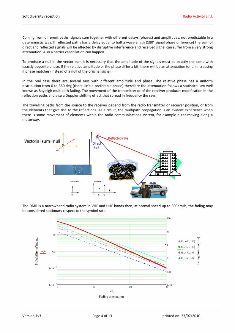
To understand fading effect, consider a simple 2 rays
model of propagation as described in the figure.
Soft diversity reception Radio Activity S.r.l.
Version 1v3 Page 4 of 13 printed on: 23/07/2010
Coming from different paths, signals sum together with different delays (phases) and amplitudes, not predictable in a
deterministic way. If reflected paths has a delay equal to half a wavelength (180° signal phase difference) the sum of
direct and reflected signals will be affected by disruptive interference and received signal can suffer from a very strong
attenuation. Also a carrier cancellation can happen.
To produce a null in the vector sum it is necessary that the amplitude of the signals must be exactly the same with
exactly opposite phase. If the relative amplitude or the phase differ a bit, there will be an attenuation (or an increasing
if phase matches) instead of a null of the original signal.
In the real case there are several rays with different amplitude and phase. The relative phase has a uniform
distribution from 0 to 360 deg (there isn’t a preferable phase) therefore the attenuation follows a statistical law well
known as Rayleigh multipath fading. The movement of the transmitter or of the receiver produces modification in the
reflection paths and also a Doppler shifting effect that spread in frequency the rays.
The travelling paths from the source to the receiver depend from the radio transmitter or receiver position, or from
the elements that give rise to the reflections. As a result, the multipath propagation is an evident experience when
there is some movement of elements within the radio communications system, for example a car moving along a
motorway.
Reflected rays
Directrays
The DMR is a narrowband radio system in VHF and UHF bands then, at normal speed up to 300Km/h, the fading may
be considered stationary respect to the symbol rate.
0 10 20 301 10
4−×
1 103−
×
0.01
0.1
1
1 103−
×
0.01
0.1
1
10
100
Fading attenuation
Probability of fading
Fading duration [ms]
pe i( )
τ dBi 450, 100, ( )
τ dBi 160, 100, ( )
τ dBi 450, 50, ( )
τ dBi 160, 50, ( )
dBi
Vectorial sum=null
Soft diversity reception Radio Activity S.r.l.
Version 1v3 Page 5 of 13 printed on: 23/07/2010
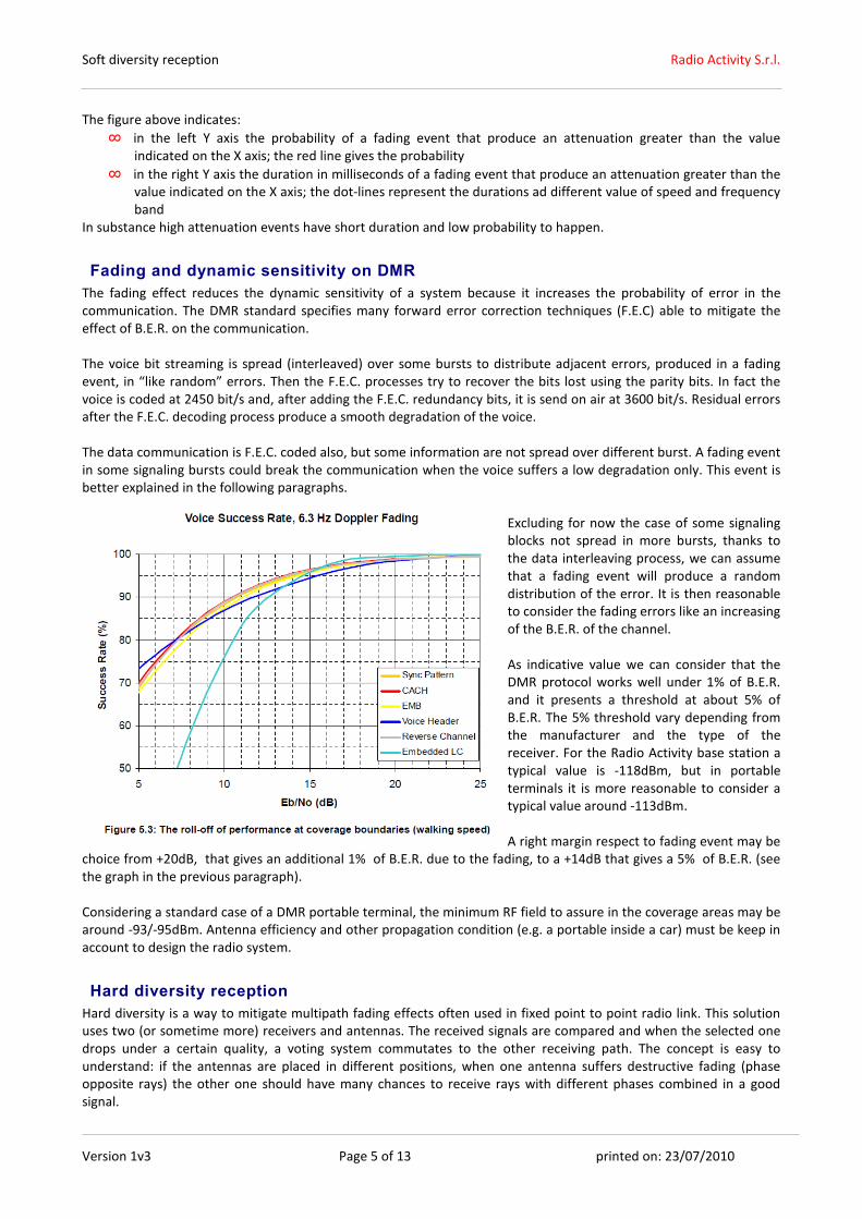
The figure above indicates:
∞ in the left Y axis the probability of a fading event that produce an attenuation greater than the value
indicated on the X axis; the red line gives the probability
∞ in the right Y axis the duration in milliseconds of a fading event that produce an attenuation greater than the
value indicated on the X axis; the dot-lines represent the durations ad different value of speed and frequency
band
In substance high attenuation events have short duration and low probability to happen.
Fading and dynamic sensitivity on DMR
The fading effect reduces the dynamic sensitivity of a system because it increases the probability of error in the
communication. The DMR standard specifies many forward error correction techniques (F.E.C) able to mitigate the
effect of B.E.R. on the communication.
The voice bit streaming is spread (interleaved) over some bursts to distribute adjacent errors, produced in a fading
event, in “like random” errors. Then the F.E.C. processes try to recover the bits lost using the parity bits. In fact the
voice is coded at 2450 bit/s and, after adding the F.E.C. redundancy bits, it is send on air at 3600 bit/s. Residual errors
after the F.E.C. decoding process produce a smooth degradation of the voice.
The data communication is F.E.C. coded also, but some information are not spread over different burst. A fading event
in some signaling bursts could break the communication when the voice suffers a low degradation only. This event is
better explained in the following paragraphs.
Excluding for now the case of some signaling
blocks not spread in more bursts, thanks to
the data interleaving process, we can assume
that a fading event will produce a random
distribution of the error. It is then reasonable
to consider the fading errors like an increasing
of the B.E.R. of the channel.
As indicative value we can consider that the
DMR protocol works well under 1% of B.E.R.
and it presents a threshold at about 5% of
B.E.R. The 5% threshold vary depending from
the manufacturer and the type of the
receiver. For the Radio Activity base station a
typical value is -118dBm, but in portable
terminals it is more reasonable to consider a
typical value around -113dBm.
A right margin respect to fading event may be
choice from +20dB, that gives an additional 1% of B.E.R. due to the fading, to a +14dB that gives a 5% of B.E.R. (see
the graph in the previous paragraph).
Considering a standard case of a DMR portable terminal, the minimum RF field to assure in the coverage areas may be
around -93/-95dBm. Antenna efficiency and other propagation condition (e.g. a portable inside a car) must be keep in
account to design the radio system.
Hard diversity reception
Hard diversity is a way to mitigate multipath fading effects often used in fixed point to point radio link. This solution
uses two (or sometime more) receivers and antennas. The received signals are compared and when the selected one
drops under a certain quality, a voting system commutates to the other receiving path. The concept is easy to
understand: if the antennas are placed in different positions, when one antenna suffers destructive fading (phase
opposite rays) the other one should have many chances to receive rays with different phases combined in a good
signal.
Soft diversity reception Radio Activity S.r.l.
Version 1v3 Page 6 of 13 printed on: 23/07/2010
RX1
RX2
Different paths produce
different phase arrivals
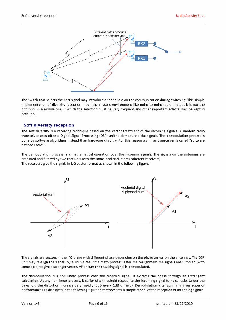
The switch that selects the best signal may introduce or not a loss on the communication during switching. This simple
implementation of diversity reception may help in static environment like point to point radio link but it is not the
optimum in a mobile one in which the selection must be very frequent and other important effects shell be kept in
account.
Soft diversity reception
The soft diversity is a receiving technique based on the vector treatment of the incoming signals. A modern radio
transceiver uses often a Digital Signal Processing (DSP) unit to demodulate the signals. The demodulation process is
done by software algorithms instead than hardware circuitry. For this reason a similar transceiver is called “software
defined radio”.
The demodulation process is a mathematical operation over the incoming signals. The signals on the antennas are
amplified and filtered by two receivers with the same local oscillators (coherent receivers).
The receivers give the signals in I/Q vector format as shown in the following figure.
I
Q
A1
A2
Vectorial sum
I
Q
A1
A2
Vectorial digitalri-phased sum
The signals are vectors in the I/Q plane with different phase depending on the phase arrival on the antennas. The DSP
unit may re-align the signals by a simple real time math process. After the realignment the signals are summed (with
some care) to give a stronger vector. After sum the resulting signal is demodulated.
The demodulation is a non linear process over the received signal. It extracts the phase through an arctangent
calculation. As any non linear process, it suffer of a threshold respect to the incoming signal to noise ratio. Under the
threshold the distortion increase very rapidly (3dB every 1dB of field). Demodulation after summing gives superior
performances as displayed in the following figure that represents a simple model of the reception of an analog signal:

Soft diversity reception Radio Activity S.r.l.
Version 1v3 Page 7 of 13 printed on: 23/07/2010
-113dBm -110dBm -107dBm -104dBm-116dBm
17dB
20dB
23dB
11dB
14dB
26dB
RF f ield
Received
S/N
Demodulator threshold level
1dB/dBm
3dB/dBm
9dB S/N gain under threshold
The soft diversity reception implements not only a switch from two antennas but is able to extract all the information
from both the antennas contemporary. This fact gives many advantages in the real cases respect to the hard diversity
(or voted diversity).
The soft diversity reception gives a number of benefits on the receiver capability of the base station:
∞ it gives 3 dB more of sensitivity
∞ it contrasts the multipath fading
∞ it reduces the de-sensitivity effect in the repeater placed at high altitude
∞ it increases significantly the coverage area of a repeater
The diversity algorithms work properly in digital and in analog mode. For analog modulations, the obtained benefit by
this technology is significant, but non determining, while for systems with digital modulation, it becomes a
fundamental requirement.
Soft diversity antenna technique is recommended in every digital communication like DMR. Radio Activity base
stations implements a very efficient digital diversity reception.
DIVERSITY RECEPTION IN A MULTIPATH FADING ENVIRONMENT
As mentioned before, using more antennas placed in different positions, the probability to have all the antennas
under destructive fading is the product of the probabilities of the single antennas.
Considering a loss of performance threshold of about 1% of B.E.R (Bit Error Rate) for a DMR communication, the figure
below shows that a system with 2 antennas reduce the B.E.R. of 100 times near the threshold!
Soft diversity reception Radio Activity S.r.l.
Version 1v3 Page 8 of 13 printed on: 23/07/2010
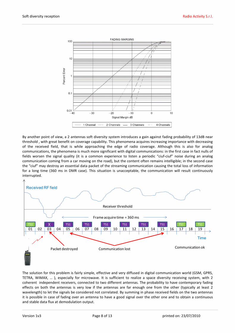
By another point of view, a 2 antennas soft diversity system introduces a gain against fading probability of 13dB near
threshold , with great benefit on coverage capability. This phenomena acquires increasing importance with decreasing
of the received field, that is while approaching the edge of radio coverage. Although this is also for analog
communications, the phenomena is much more significant with digital communications: in the first case in fact nulls of
fields worsen the signal quality (it is a common experience to listen a periodic “ciuf-ciuf” noise during an analog
communication coming from a car moving on the road), but the content often remains intelligible; in the second case
the “ciuf” may destroy an essential data packet of the streaming communication causing the total loss of information
for a long time (360 ms in DMR case). This situation is unacceptable, the communication will result continuously
interrupted.
Frame acquire time = 360 ms
TS1
01 0302 04 0605 07 0908 10 11 1312 14 1615X
Packet destroyed
TS1 TS1 TS1 TS1 TS1 TS1
17 1918
TS1
Communication lost
Time
ReceivedRF field
TS1
Communication ok
Receiver threshold
The solution for this problem is fairly simple, effective and very diffused in digital communication world (GSM, GPRS,
TETRA, WiMAX, … ), especially for microwave. It is sufficient to realize a space diversity receiving system, with 2
coherent independent receivers, connected to two different antennas. The probability to have contemporary fading
effects on both the antennas is very low if the antennas are far enough one from the other (typically at least 2
wavelength) to let the signals be considered not correlated. By summing in phase received fields on the two antennas
it is possible in case of fading over an antenna to have a good signal over the other one and to obtain a continuous
and stable data flux at demodulation output.
Soft diversity reception Radio Activity S.r.l.
Version 1v3 Page 9 of 13 printed on: 23/07/2010
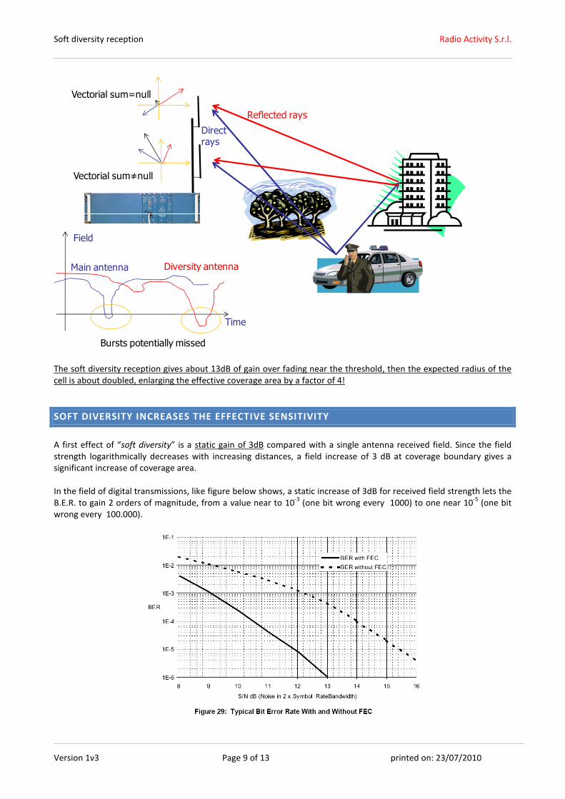
Vectorial sum=null
Vectorial sum≠null
Reflected rays
Directrays
Main antenna Diversity antenna
Time
Field
Bursts potentially missed
The soft diversity reception gives about 13dB of gain over fading near the threshold, then the expected radius of the
cell is about doubled, enlarging the effective coverage area by a factor of 4!
SOFT DIVERSITY INCREASES THE EFFECTIVE SENSITIVITY
A first effect of “soft diversity” is a static gain of 3dB compared with a single antenna received field. Since the field
strength logarithmically decreases with increasing distances, a field increase of 3 dB at coverage boundary gives a
significant increase of coverage area.
In the field of digital transmissions, like figure below shows, a static increase of 3dB for received field strength lets the
B.E.R. to gain 2 orders of magnitude, from a value near to 10-3
(one bit wrong every 1000) to one near 10-5
(one bit
wrong every 100.000).

Soft diversity reception Radio Activity S.r.l.
Version 1v3 Page 10 of 13 printed on: 23/07/2010
The automatic antenna phase alignment gives also a greater directivity of radiant system and so it gives a greater
rejection of interfering signals as explained in the following.
Generally radio networks suffer from an unbalance between up-link and down-link, due to:
∞ different transmission power (10-20 W from base station, versus 1-5W from hand-held mobiles)
∞ bigger radio noise floor received by repeating sites which, being placed at higher altitude, collects noise from
a bigger area compared with the mobile terminal
∞ stronger presences on interfering signals
The base stations of a mobile radio network are normally placed on the top of hill or mountain to serve a wide area.
This choice is obvious to maximize the down-link RF budget but it may introduce some troubles in the up-link. In fact a
repeater placed at high altitude could receive many signals that reduce the “on air” sensitivity.
Industrial noise
Base station
About 3..+10 dB sensitivity decrease
Radiated Power+30..+37 dBm
Radiated Power+40..+43 dBm
Strong signals from broadcast/GSM stations
The strong signals sourced from near GSM cellular base stations or from broadcast stations create an elettromagnetic
pollution in the receiving band of the repeater. So it collects noise from a big area that reduce the effective sensitivity.
A band-pass filter placed before the RX input port may help for the blocking problems (“out of band” signals too
strong that saturate the receiver) but it doesn’t produce any effect for the “in band” noise. The “in band” noise is “on
air”, therefore there isn’t a way to filter it. An effective sensitivity decrease of -3 to -10dB is a common value in most
repeater sites, more palpable in VHF band than in UHF one.
At the opposite, a user calling with a portable device placed in a quiet land may receive a very low ambient noise. He
will receive very well the base station signal. Unfortunately when he try to transmit a signal to the base station the
lower RF power (1-5W), in conjunction with the lower effective sensitivity of the repeater, penalizes the RF up-link
budget. In some area a user may receive a good signal from the network but he may not be able to communicate
through the network.
This situation may produce unpleasant effects. A user, listening very well the base station without receive answer
from the Operative Center, will imagine that in the Operative Center all people are sleeping! In fact none had received
his communication.
The RF budged link may be 5 to 15 dB more favourable in the broadcasting than in network access. “Soft diversity”
function significantly increases radio system receiving performances in both analog and digital working.
Soft diversity reception Radio Activity S.r.l.
Version 1v3 Page 11 of 13 printed on: 23/07/2010
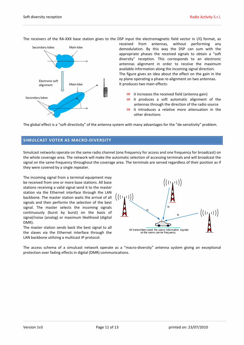
The receivers of the RA-XXX base station gives to the DSP input the electromagnetic field vector in I/Q format, as
received from antennas, without performing any
demodulation. By this way the DSP can sum with the
appropriate phases the received signals to obtain a “soft
diversity” reception. This corresponds to an electronic
antennas alignment in order to receive the maximum
available information along the incoming signal direction.
The figure gives an idea about the effect on the gain in the
xy plane operating a phase re-alignment on two antennas.
It produces two main effects:
∞ it increases the received field (antenna gain)
∞ it produces a soft automatic alignment of the
antennas through the direction of the radio source
∞ it introduces a relative more attenuation in the
other directions
The global effect is a “soft directivity” of the antenna system with many advantages for the “de-sensitivity” problem.
SIMULCAST VOTER AS MACRO-DIVERSITY
Simulcast networks operate on the same radio channel (one frequency for access and one frequency for broadcast) on
the whole coverage area. The network will make the automatic selection of accessing terminals and will broadcast the
signal on the same frequency throughout the coverage area. The terminals are served regardless of their position as if
they were covered by a single repeater.
The incoming signal from a terminal equipment may
be received from one or more base stations. All base
stations receiving a valid signal send it to the master
station via the Ethernet interface through the LAN
backbone. The master station waits the arrival of all
signals and then performs the selection of the best
signal. The master selects the incoming signals
continuously (burst by burst) on the basis of
signal/noise (analog) or maximum likelihood (digital
DMR).
The master station sends back the best signal to all
the slaves via the Ethernet interface through the
LAN backbone utilizing a multicast IP protocol.
The access schema of a simulcast network operate as a “macro-diversity” antenna system giving an exceptional
protection over fading effects in digital (DMR) communications.
All transmitters send the same information signalson the same carrier frequency
fc
fc
fc
Main lobeSecondary lobes
Secondary lobes
Main lobeElectronic soft
alignment

Soft diversity reception Radio Activity S.r.l.
Version 1v3 Page 12 of 13 printed on: 23/07/2010
SUGGESTED ANTENNA SYSTEM
The insertion of a diversity antenna is a simple operation. The typical branching schema is explained in the following
figure.
TXRX main
Double notch filters
(internal)
RX div.
Additional (external) diversity
filter (if needed) to prevent RX
blocking due to TX power
emission
> 2 λ
The antenna space separation should be more than twice the wavelength (e.g. >4m in VHF band). In this condition the
coupling factor of two vertical dipole antenna placed on the same vertical axe is about -40dB as displayed in the
following graph:
No special need is request for the diversity antenna, it works
in reception only. A simple dipole should be enough.
The main antenna is connected through the duplexer filter
to the main receiver and to the transmitter.
The diversity antenna is connected to the diversity receiver
through a (notch) filter that suppresses the residual TX signal
to avoid blocking effect on the diversity reception path. A
reasonable (and easy to obtain) attenuation at the TX
frequency may be 40dB or more. See the maximum blocking
rejection of the receiver below to decide if insert or not a
filter on the diversity receiver:
-53dBm
-46dBm
-53dBm
-113dBm
-40dBm
-32dBm
+/- 12.5KHz
+/- 25.0KHz
+/- 50KHz +/- 1MHz
Desired signalFrequency
offset
1dB RX de-sensitivity threshold mask
Max RX
input level
TX residual
In the case of multicarrier branching system, a good implementation may be suggested by the following figure (RF
insulators are not drawn) :

Soft diversity reception Radio Activity S.r.l.
Version 1v3 Page 13 of 13 printed on: 23/07/2010
TX
RX main
Double notch filters
(internal)
RX div.
> 2 λ
- 40dB coupling
TX
RX main
RX div.
Carrier 1
Carrier 2
The approach above maximizes the available RF power on the antennas and, at the same time, optimizes the receiving
performance.
A similar approach may be used to built multi carrier realizations combining the TX and the RX to take advantage of
diversity antenna schema. The drawing below suggest a very compact and effective branching system with diversity
antenna for 4 carriers giving an 8 channels system.
TX
RX main
Double notch filters
RX div.
> 2 λ / -
40dB
coupling
RX main
RX div.
Carrier 1
Carrier 2
CH3 CH4
CH1 CH2
TX
-3dB
+6dB
TX
RX main
Double notch filters
RX div.
RX main
RX div.
Carrier 3
Carrier 4
TX
-3dB
+6dB
3 dB
directional
coupler
3 dB
directional
coupler
RF Isolator
RF Isolator
RF Isolator
RF Isolator
RX amplifier
and divider
RX amplifier
and divider
Coax
Coax