Embed Size (px)
Citation preview
SocketModem™ GSM/GPRSEmbedded Data/Fax Wireless Modem
MTSMC-G-F1 – Global GSM/GPRS Class 10, 900/1800 MHz
MTSMC-G-F2 – Global GSM/GPRS Class 10, 850/1900 MHz
Developer’s Guide
Table of Contents
3
Table of Contents
CHAPTER 1 – PRODUCT DESCRIPTION AND SPECIFICATIONS.......................................................... 4PRODUCT DESCRIPTION ............................................................................................................................... 4APPLICATIONS.............................................................................................................................................. 4PRODUCT FEATURES.................................................................................................................................... 5FEATURE DETAILS........................................................................................................................................ 5DEVELOPER’S KIT ........................................................................................................................................ 5TECHNICAL SPECIFICATIONS......................................................................................................................... 6RELATED MANUALS...................................................................................................................................... 6ADDITIONAL INFORMATION............................................................................................................................ 6
CHAPTER 2 – MECHANICAL SPECIFICATIONS ...................................................................................... 7PHYSICAL DIMENSIONS................................................................................................................................. 7PIN CONFIGURATIONS .................................................................................................................................. 8
Pin Descriptions...................................................................................................................................... 8
CHAPTER 3 – ELECTRICAL CHARACTERISTICS ................................................................................... 9I/O ELECTRICAL CHARACTERISTICS .............................................................................................................. 9POWER CONSUMPTION................................................................................................................................. 9SIM INTERFACE ELECTRICAL CHARACTERISTICS ......................................................................................... 10HANDLING PRECAUTIONS ........................................................................................................................... 10
CHAPTER 4 – SOCKETMODEM INTERFACES....................................................................................... 11FLASHING LED .......................................................................................................................................... 11SIM INTERFACE ......................................................................................................................................... 11RF INTERFACE........................................................................................................................................... 12
RF Connector ....................................................................................................................................... 12RF Performances.................................................................................................................................. 12
CHAPTER 5 – SOCKETMODEM TEST BOARD ...................................................................................... 13SERIAL TEST/DEMO BOARD COMPONENTS.................................................................................................. 13SERIAL TEST/DEMO BOARD BLOCK DIAGRAM.............................................................................................. 13
CHAPTER 6 – APPLICATION CONSIDERATIONS.................................................................................. 16GENERAL GUIDELINES FOR THE USE OF THE SOCKETMODEM....................................................................... 16
Hardware and RF ................................................................................................................................. 16The Antenna ......................................................................................................................................... 16
FIRMWARE UPGRADE ................................................................................................................................. 16INITIAL CONFIGURATION USING MOBILE PHONETOOLS................................................................................. 16
APPENDIX A – SAFETY PRECAUTIONS & REGULATORY STANDARDS COMPLIANCE.................. 17SAFETY PRECAUTIONS ............................................................................................................................... 17
RF Safety.............................................................................................................................................. 17General Safety...................................................................................................................................... 18Safety Standards .................................................................................................................................. 19RF Exposures ....................................................................................................................................... 19Instructions to OEMs ............................................................................................................................ 19
REGULATORY STANDARDS COMPLIANCE ..................................................................................................... 20GSM compliance .................................................................................................................................. 20
APPENDIX B – SOURCES FOR PERIPHERAL DEVICES ...................................................................... 21GSM ANTENNA.......................................................................................................................................... 21
APPENDIX C – AT COMMAND LIST ........................................................................................................ 22
APPENDIX D – ACRONYMS AND ABBREVIATIONS ............................................................................. 26
INDEX ......................................................................................................................................................... 27
Chapter 1 – Product Description and Specifications
4
Chapter 1 – Product Description andSpecifications
Product Description
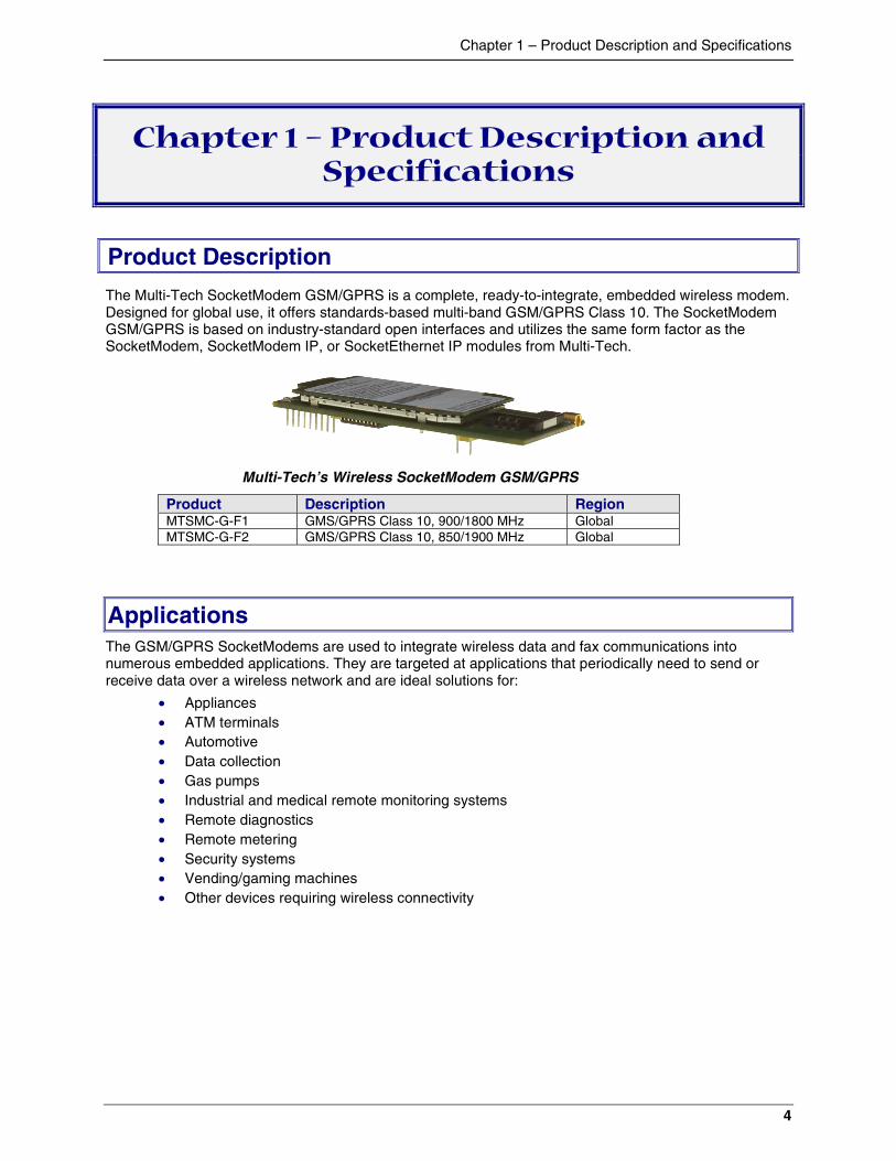
The Multi-Tech SocketModem GSM/GPRS is a complete, ready-to-integrate, embedded wireless modem.Designed for global use, it offers standards-based multi-band GSM/GPRS Class 10. The SocketModemGSM/GPRS is based on industry-standard open interfaces and utilizes the same form factor as theSocketModem, SocketModem IP, or SocketEthernet IP modules from Multi-Tech.
Multi-Tech’s Wireless SocketModem GSM/GPRS
Product Description RegionMTSMC-G-F1 GMS/GPRS Class 10, 900/1800 MHz GlobalMTSMC-G-F2 GMS/GPRS Class 10, 850/1900 MHz Global
ApplicationsThe GSM/GPRS SocketModems are used to integrate wireless data and fax communications intonumerous embedded applications. They are targeted at applications that periodically need to send orreceive data over a wireless network and are ideal solutions for:
� Appliances� ATM terminals� Automotive� Data collection� Gas pumps� Industrial and medical remote monitoring systems� Remote diagnostics� Remote metering� Security systems� Vending/gaming machines� Other devices requiring wireless connectivity
Chapter 1 – Product Description and Specifications
5
Product Features� GPRS Class 10� Dual-band 850/1900 or 900/1800 GSM/GPRS� GSM Class 1 and Class 2 Group 3 FAX� Short Message Services features including text and PDU, point to point, cell broadcast� 14.4K GSM circuit switched data� MMCX antenna connector and SIM socket� Serial interface supports DTE speeds to 115.2K� AT command compatible*� V.42bis data compression� ME + SIM phone book management
*AT Commands - AT commands for this product are published in a separate document available on thesystem CD and from Multi-Tech. For a copy of this documents contact OEM Sales at: [email protected] or call (800) 972-2439.
Feature DetailsIntegration Reduces Space, Power, and Cost – The SocketModem GSM/GPRS integrates thecontroller, RF transceiver, and antenna interface in one module. This integration requires low power,low real estate and provides an overall reduction in costs.
Reduces Development Time – The SocketModem GSM/GPRS can make your existing and nextgeneration device, machine, or system, communication-ready without requiring significant hardwarechanges to its design. This complete, ready-to-integrate wireless SocketModem allows you toenhance your product while you focus on developing its core features.
Short Message Services – The SocketModem GSM/GPRS offers SMS features such as text andPDU, point-to-point (MT/MO) and cell broadcast.
Management Features – The SocketModem GSM/GPRS provides advanced management featuresthat include: phone book management, fixed dialing number, real time clock and alarm management.
Industry-standard Modem Commands – The SocketModem GSM/GPRS provides industry-standard AT-style commands for ease of integration into your existing software application.
SocketModem Pin-Out – The SocketModem GSM/GPRS interfaces easily with existing productsthrough a standard serial communication channel. The complete on-board RF transceiver interfaceswith an antenna for direct connection to wireless SMS, circuit-switched dial-up, or packet datanetworks. The SocketModem also includes an onboard LED to display network status. TheSocketModem is a Data Terminal Equipment (DTE) device with serial asynchronous protocol support.The serial DTE channel is capable of transfer speeds to 115.2K bps and can be interfaced directly toa UART or microcontroller.
Developer’s KitThe SocketModem GSM/GPRS Developer’s Kit allows you to plug in the SocketModem and use it fortesting, programming, and evaluation. The kit includes:
� one development board� RS-232 DB-25 connector� universal power supply� antenna� RS-232 cable
Chapter 1 – Product Description and Specifications
6
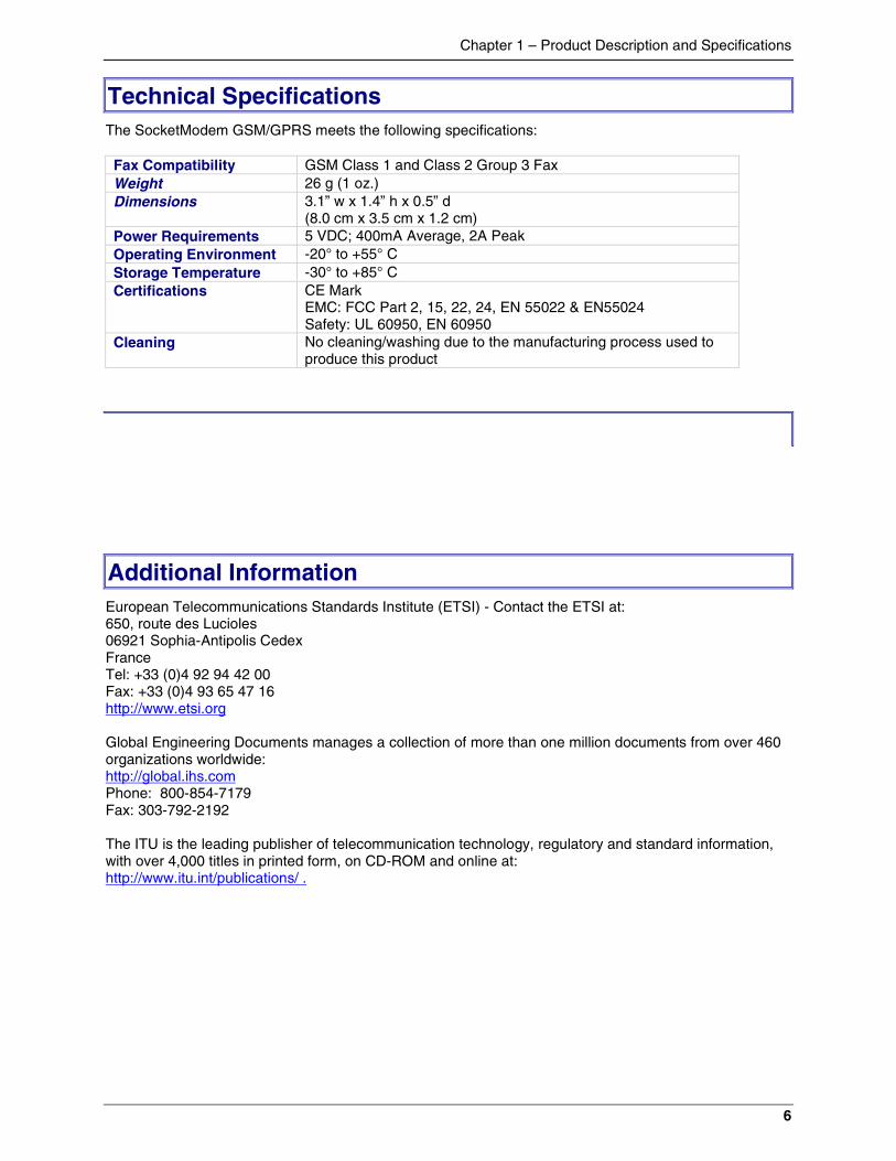
Technical SpecificationsThe SocketModem GSM/GPRS meets the following specifications:
Fax Compatibility GSM Class 1 and Class 2 Group 3 FaxWeight 26 g (1 oz.)Dimensions 3.1” w x 1.4” h x 0.5” d
(8.0 cm x 3.5 cm x 1.2 cm)Power Requirements 5 VDC; 400mA Average, 2A PeakOperating Environment -20° to +55° CStorage Temperature -30° to +85° CCertifications CE Mark
EMC: FCC Part 2, 15, 22, 24, EN 55022 & EN55024Safety: UL 60950, EN 60950
Cleaning No cleaning/washing due to the manufacturing process used toproduce this product
Additional InformationEuropean Telecommunications Standards Institute (ETSI) - Contact the ETSI at:650, route des Lucioles06921 Sophia-Antipolis CedexFranceTel: +33 (0)4 92 94 42 00Fax: +33 (0)4 93 65 47 16http://www.etsi.org
Global Engineering Documents manages a collection of more than one million documents from over 460organizations worldwide:http://global.ihs.comPhone: 800-854-7179Fax: 303-792-2192
The ITU is the leading publisher of telecommunication technology, regulatory and standard information,with over 4,000 titles in printed form, on CD-ROM and online at:http://www.itu.int/publications/ .
Chapter 2 – Mechanical Specifications
7
Chapter 2 – Mechanical Specifications
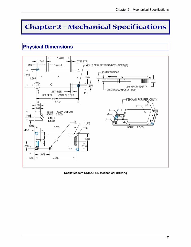
Physical Dimensions
SocketModem GSM/GPRS Mechanical Drawing
Chapter 2 – Mechanical Specifications
8
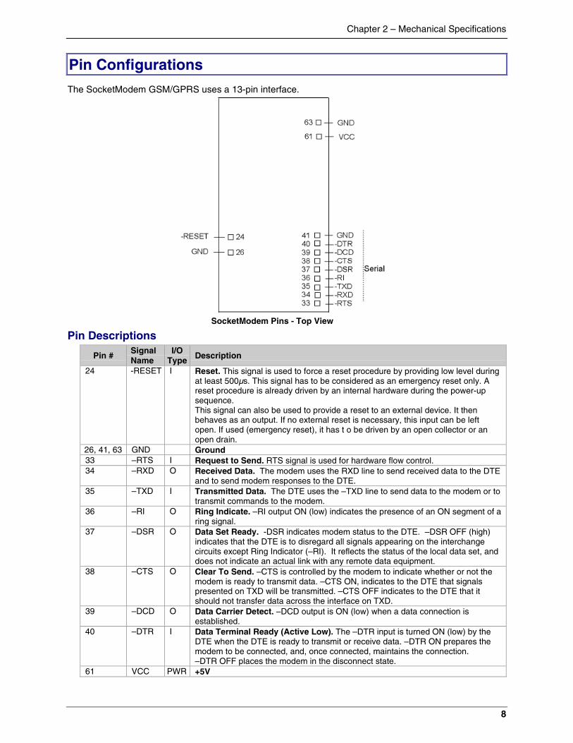
Pin Configurations
The SocketModem GSM/GPRS uses a 13-pin interface.
SocketModem Pins - Top View
Pin Descriptions
Pin #SignalName
I/OType Description
24 -RESET I Reset. This signal is used to force a reset procedure by providing low level duringat least 500µs. This signal has to be considered as an emergency reset only. Areset procedure is already driven by an internal hardware during the power-upsequence.This signal can also be used to provide a reset to an external device. It thenbehaves as an output. If no external reset is necessary, this input can be leftopen. If used (emergency reset), it has t o be driven by an open collector or anopen drain.
26, 41, 63 GND Ground33 –RTS I Request to Send. RTS signal is used for hardware flow control.34 –RXD O Received Data. The modem uses the RXD line to send received data to the DTE
and to send modem responses to the DTE.35 –TXD I Transmitted Data. The DTE uses the –TXD line to send data to the modem or to
transmit commands to the modem.36 –RI O Ring Indicate. –RI output ON (low) indicates the presence of an ON segment of a
ring signal.37 –DSR O Data Set Ready. -DSR indicates modem status to the DTE. –DSR OFF (high)
indicates that the DTE is to disregard all signals appearing on the interchangecircuits except Ring Indicator (–RI). It reflects the status of the local data set, anddoes not indicate an actual link with any remote data equipment.
38 –CTS O Clear To Send. –CTS is controlled by the modem to indicate whether or not themodem is ready to transmit data. –CTS ON, indicates to the DTE that signalspresented on TXD will be transmitted. –CTS OFF indicates to the DTE that itshould not transfer data across the interface on TXD.
39 –DCD O Data Carrier Detect. –DCD output is ON (low) when a data connection isestablished.
40 –DTR I Data Terminal Ready (Active Low). The –DTR input is turned ON (low) by theDTE when the DTE is ready to transmit or receive data. –DTR ON prepares themodem to be connected, and, once connected, maintains the connection.–DTR OFF places the modem in the disconnect state.
61 VCC PWR +5V
Chapter 3 – Electrical Characteristics
9
Chapter 3 – Electrical Characteristics
Electrical characteristics for the 5V Serial SocketModem are presented in this chapter.
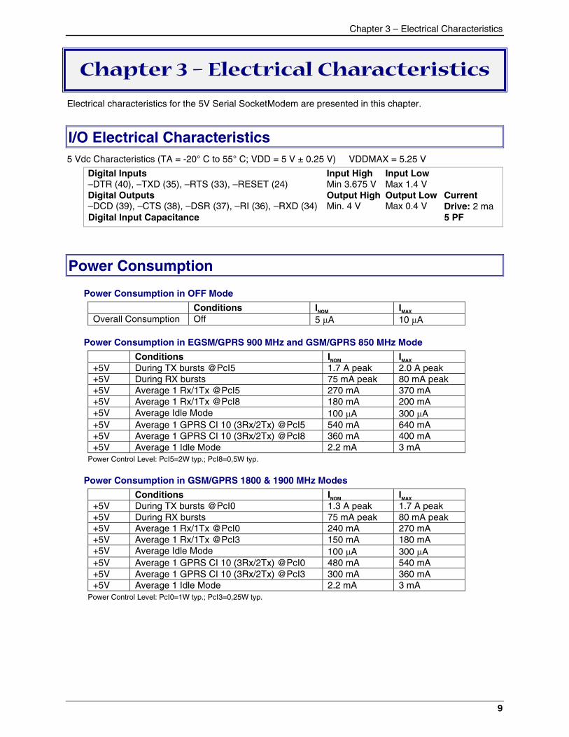
I/O Electrical Characteristics5 Vdc Characteristics (TA = -20° C to 55° C; VDD = 5 V ± 0.25 V) VDDMAX = 5.25 V
Digital Inputs–DTR (40), –TXD (35), –RTS (33), –RESET (24)
Input HighMin 3.675 V
Input LowMax 1.4 V
Digital Outputs–DCD (39), –CTS (38), –DSR (37), –RI (36), –RXD (34)
Output HighMin. 4 V
Output LowMax 0.4 V
CurrentDrive: 2 ma
Digital Input Capacitance 5 PF
Power Consumption
Power Consumption in OFF Mode
Conditions INOM IMAX
Overall Consumption Off 5 �A 10 �A
Power Consumption in EGSM/GPRS 900 MHz and GSM/GPRS 850 MHz Mode
Conditions INOM IMAX
+5V During TX bursts @PcI5 1.7 A peak 2.0 A peak+5V During RX bursts 75 mA peak 80 mA peak+5V Average 1 Rx/1Tx @PcI5 270 mA 370 mA+5V Average 1 Rx/1Tx @PcI8 180 mA 200 mA+5V Average Idle Mode 100 �A 300 �A+5V Average 1 GPRS CI 10 (3Rx/2Tx) @PcI5 540 mA 640 mA+5V Average 1 GPRS CI 10 (3Rx/2Tx) @PcI8 360 mA 400 mA+5V Average 1 Idle Mode 2.2 mA 3 mA
Power Control Level: PcI5=2W typ.; PcI8=0,5W typ.
Power Consumption in GSM/GPRS 1800 & 1900 MHz Modes
Conditions INOM IMAX
+5V During TX bursts @PcI0 1.3 A peak 1.7 A peak+5V During RX bursts 75 mA peak 80 mA peak+5V Average 1 Rx/1Tx @PcI0 240 mA 270 mA+5V Average 1 Rx/1Tx @PcI3 150 mA 180 mA+5V Average Idle Mode 100 �A 300 �A+5V Average 1 GPRS CI 10 (3Rx/2Tx) @PcI0 480 mA 540 mA+5V Average 1 GPRS CI 10 (3Rx/2Tx) @PcI3 300 mA 360 mA+5V Average 1 Idle Mode 2.2 mA 3 mA
Power Control Level: PcI0=1W typ.; PcI3=0,25W typ.
Chapter 3 – Electrical Characteristics
10
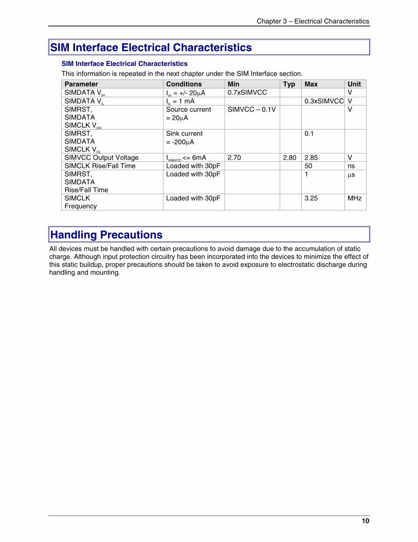
SIM Interface Electrical CharacteristicsSIM Interface Electrical CharacteristicsThis information is repeated in the next chapter under the SIM Interface section.
Parameter Conditions Min Typ Max UnitSIMDATA VIH IIH = +/- 20�A 0.7xSIMVCC VSIMDATA VIL IIL = 1 mA 0.3xSIMVCC VSIMRST,SIMDATASIMCLK VOH
Source current= 20�A
SIMVCC – 0.1V V
SIMRST,SIMDATASIMCLK VOL
Sink current= -200�A
0.1
SIMVCC Output Voltage ISIMVCC <= 6mA 2.70 2.80 2.85 VSIMCLK Rise/Fall Time Loaded with 30pF 50 nsSIMRST,SIMDATARise/Fall Time
Loaded with 30pF 1 �s
SIMCLKFrequency
Loaded with 30pF 3.25 MHz
Handling PrecautionsAll devices must be handled with certain precautions to avoid damage due to the accumulation of staticcharge. Although input protection circuitry has been incorporated into the devices to minimize the effect ofthis static buildup, proper precautions should be taken to avoid exposure to electrostatic discharge duringhandling and mounting.
Chapter 4 - SocketModem Interfaces
11
Chapter 4 – SocketModem Interfaces
This chapter describes the SocketModem interfaces.� Flashing LED� SIM Interface� RF Interface
Flashing LEDThe flashing LED signal is used to indicate the working mode of the SocketModem.
LED and SocketModem Status
Signal SocketModem StatusOFF Download mode or switched OFF>
Continuously lit Switched ON (not registered on the network)ONFlashing Switched ON (registered on the network)
SIM InterfaceThe internal SIM interface of the SocketModule supports 3V SIMs only.Note: This interface is fully compliant with GSM 11.11 recommendations concerning the SIM functionality.
Five Signals Are AvailableSIMVCC: SIM power supply.SIMRST: reset.SIMCLK: clock.SIMDATA: I/O port.SIMPRES1 SIM card detect.
Chapter 4 - SocketModem Interfaces
12
RF InterfaceThe impedance is 50 Ohms nominal.
RF ConnectorThe RF connector is MMCX standard type. An antenna can be directly connected through the matingconnector or using a small adapter.
RF PerformancesRF performances are compliant with the ETSI recommendation 05.05 and 11.10.The main parameters are:
Receiver:� EGSM Sensitivity : < -104 dBm� GSM 1800/GSM 1900 Sensitivity : < -102 dBm� Selectivity @ 200 kHz : > +9 dBc� Selectivity @ 400 kHz : > +41 dBc� Dynamic range : 62 dB� Intermodulation : > -43 dBm� Co-channel rejection : + 9 dBc
Transmitter:� Maximum output power (EGSM) : 33 dBm +/- 2 dB� Maximum output power (DCS/PCS) : 30 dBm +/- 2 dB� Minimum output power (EGSM): 5 dBm +/- 5 dB� Minimum output power (DCS/PCS): 0 dBm +/- 5 dB� H2 level : < -30 dBm� H3 level : < -30 dBm� Noise in 925 - 935 MHz : < -67 dBm� Noise in 935 - 960 MHz : < -79 dBm� Noise in 1805 - 1880 MHz : < -71 dBm� Phase error at peak power : < 5 ° RMS� Frequency error : +/- 0.1 ppm max
Chapter 5 – SocketModem Test Board
13
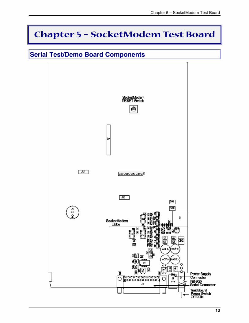
Chapter 5 – SocketModem Test Board
Serial Test/Demo Board Components
Chapter 5 – SocketModem Test Board
14
Chapter 5 – SocketModem Test Board
15
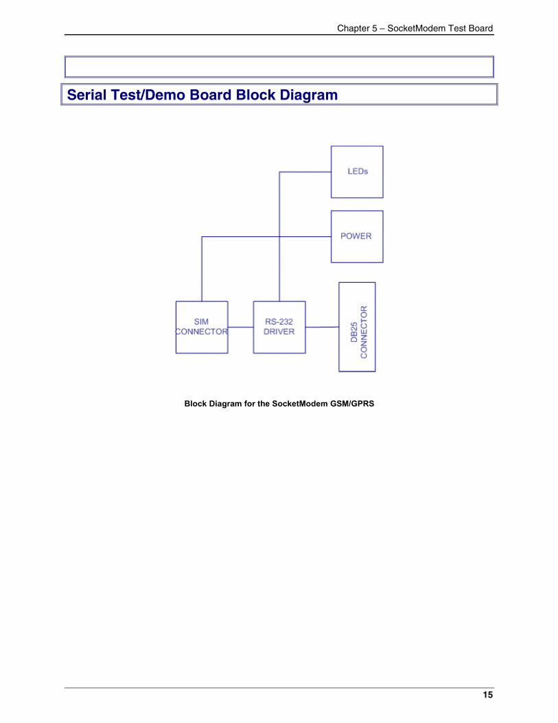
Serial Test/Demo Board Block Diagram
Block Diagram for the SocketModem GSM/GPRS
Chapter 6 – Application Considerations
16
Chapter 6 – ApplicationConsiderations
General Guidelines for the Use of the SocketModem
Hardware and RF� Ground plane: Multi-Tech recommends having a common ground plane for analog, digital and RF
grounds.� ESD protection on serial link, …� Possible spurious emission radiated by the application to the RF receiver in the receiver band
The AntennaThe antenna sub-system and integration in the application is a major issue. It is a major issue in thechoice of the antenna cable (type, length, performances, thermal resistance, etc.)
These elements could affect GSM performances such as sensitivity and emitted power.
The antenna should be isolated as much as possible from the digital circuitry including the interfacesignals.
Multi-Tech recommends shielding the terminal. On terminals including the antenna, a poor shielding coulddramatically affect the sensitivity of the terminal. Subsequently, the power emitted through the antennacould affect the application.
Firmware UpgradeThe SocketModem firmware is stored in flash memory and it can easily be upgraded.The upgrade procedure is based on the Xmodem protocol (AT+WDWL command).
Nominal Upgrade ProcedureThe firmware file can be downloaded into the modem using the Xmodem protocol. To enter thismode, the AT+WDWL command (see description in the AT command manual) has to be sent to theSocketModem.
The necessary serial signals to proceed with the Xmodem downloading are: Rx, Tx, RTS, CTS, GND.
Initial Configuration Using Mobile PhoneToolsFor initial configuration of your wireless device, Multi-Tech offers a Windows-based mobilePhoneTools application.
To load Mobile PhoneTools, click the Mobile PhoneTools icon on the system CD and follow the on-screen prompts.
Appendix A – Safety Precautions and Regulatory Standards Compliance
17
Appendix A – Safety Precautions &Regulatory Standards Compliance
Safety Precautions
IMPORTANT!FOR THE EFFICIENT AND SAFE OPERATIONOF YOUR GSM INTEGRATED MODEM READTHIS INFORMATION BEFORE USE.
RF Safety
GeneralYour SocketModem is based on the GSM standard for cellular technology. The GSM standard is spreadall over the world. It covers Europe, Asia, and some parts of America and Africa. This is the most usedtelecommunication standard. Your modem is actually a low power radio transmitter and receiver. It sendsout and receives radio frequency energy. When you use your SocketModem integrated modem, thecellular system, which handles your calls controls both the radio frequency and the power level of yourcellular modem.
Exposure to RF EnergyThere has been some public concern about possible health effects of using GSM modems. Althoughresearch on health effects from RF energy has focused on the current RF technology for many years,scientists have begun research regarding newer radio technologies, such as GSM. After existing researchhad been reviewed, and after compliance to all applicable safety standards had been tested, it has beenconcluded that the product was fitted for use. If you are concerned about exposure to RF energy thereare things you can do to minimize exposure. Obviously, limiting the duration of your calls will reduce yourexposure to RF energy. In addition, you can reduce RF exposure by operating your cellular modemefficiently by following the below guidelines.
Efficient Modem OperationFor your modem to operate at the lowest power level, consistent with satisfactory call quality :
� If your modem has an extendible antenna, extend it fully. Some models allow you to place a callwith the antenna retracted. However your modem operates more efficiently with the antenna fullyextended.
� Do not hold the antenna when the modem is « IN USE ». Holding the antenna affects call qualityand may cause the modem to operate at a higher power level than needed.
Antenna Care and ReplacementDo not use the modem with a damaged antenna. If a damaged antenna comes into contact with the skin,a minor burn may result. Replace a damaged antenna immediately. Consult your manual to see if youmay change the antenna yourself. If so, use only a manufacturer-approved antenna. Otherwise, haveyour antenna repaired by a qualified technician. Use only the supplied or approved antenna.Unauthorized antennas, modifications, or attachments could damage the modem and may contravenelocal RF emission regulations or invalidate type approval.
Appendix A – Safety Precautions and Regulatory Standards Compliance
18
General Safety
DrivingCheck the laws and the regulations regarding the use of cellular devices in the area where you have todrive as you always have to comply with them. When using your modem while driving, please : give fullattention to driving, pull off the road and park before making or answering a call if driving conditions sorequire.
Electronic DevicesMost electronic equipment, for example in hospitals and motor vehicles is shielded from RF energy.However RF energy may affect some improperly shielded electronic equipment.
Vehicle Electronic EquipmentCheck your vehicle manufacturer representative to determine if any on-board electronic equipment isadequately shielded from RF energy.
Medical Electronic EquipmentConsult the manufacturer of any personal medical devices (such as pacemakers, hearing aids, etc...) todetermine if they are adequately shielded from external RF energy. Turn your modem OFF in health carefacilities when any regulations posted in the area instruct you to do so. Hospitals or health care facilitiesmay be using RF monitoring equipment.
AircraftTurn your modem OFF before boarding any aircraft.
� Use it on the ground only with crew permission.� Do not use it in the air.
To prevent possible interference with aircraft systems, Federal Aviation Administration (FAA) regulationsrequire you to have permission from a crew member to use your modem while the aircraft is on theground. To prevent interference with cellular systems, local RF regulations prohibit using your modemwhile airborne.
ChildrenDo not allow children to play with your modem. It is not a toy. Children could hurt themselves or others (bypoking themselves or others in the eye with the antenna, for example). Children could damage themodem, or make calls that increase your modem bills.
Blasting AreasTo avoid interfering with blasting operations, turn your unit OFF when in a « blasting area » or in areasposted : « turn off two-way radio ». Construction crew often use remote control RF devices to set offexplosives.
Potentially Explosive AtmospheresTurn your modem OFF when in any area with a potentially explosive atmosphere. It is rare, but yourmodem or its accessories could generate sparks. Sparks in such areas could cause an explosion or fireresulting in bodily injuries or even death. Areas with a potentially explosive atmosphere are often, but notalways, clearly marked. They include fueling areas such as petrol stations; below decks on boats; fuel orchemical transfer or storage facilities; and areas where the air contains chemicals or particles, such asgrain, dust, or metal powders. Do not transport or store flammable gas, liquid, or explosives, in thecompartment of your vehicle, which contains your modem or accessories. Before using your modem in avehicle powered by liquefied petroleum gas (such as propane or butane) ensure that the vehicle complieswith the relevant fire and safety regulations of the country in which the vehicle is to be used.
Appendix A – Safety Precautions and Regulatory Standards Compliance
19
Safety Standards
THIS WIRELESS SOCKETMODEM COMPLIES WITH ALL APPLICABLE RF SAFETY STANDARDS.This cellular modem meets the standards and recommendations for the protection of public exposure toRF electromagnetic energy established by governmental bodies and other qualified organizations, suchas the following :
� Directives of the European Community,� Directorate General V in Matters of Radio Frequency Electromagnetic Energy
RF Exposures
Pursuant to 47 CFR § 24.52 of the FCC Rules and Regulations, personal communications services (PCS)equipment is subject to the radio frequency radiation exposure requirements specified in § 1.1307(b), §2.1091 and § 2.1093 as appropriate.
The Multi-Tech SocketModem is a GSM (PCS 1900) terminal which operates in the US licensed PCSfrequency spectrum. The device transmits over the 1850-1910 MHz band and receives over the 1930-1990 MHz Band. Mult-Tech Systems, Inc. certifies that it has determined that the Modem complies withthe RF hazard requirements applicable to broadband PCS equipment operating under the authority of 47CFR Part 24, Subpart E of the FCC Rules and Regulations. This determination is dependent uponinstallation, operation and use of the equipment in accordance with all instructions provided.
The modem is designed for and intended to be used in fixed and mobile applications. "Fixed" means thatthe device is physically secured at one location and is not able to be easily moved to another location."Mobile" means that the device is designed to be used in other than fixed locations and generally in sucha way that a separation distance of at least 20 cm is normally maintained between the transmitter'santenna and the body of the user or nearby persons. The Modem is not designed for or intended to beused in portable applications (within 20 cm of the body of the user) and such uses are strictly prohibited.To ensure that the unit complies with current FCC regulations limiting both maximum RF output powerand human exposure to radio frequency radiation, a separation distance of at least 20 cm must bemaintained between the unit's antenna and the body of the user and any nearby persons at all times andin all applications and uses. Additionally, in mobile applications, maximum antenna gain must not exceed3 dBi (to comply with Section 24.232(b) and is limited to 7 dBi for fixed applications. Finally, the tune-upprocedure for the O9EM2113 ensures that the maximum RF output power of the device does not exceed30.0 dBm within the variations that can be expected due to quantity production and testing on a statisticalbasis.
Instructions to OEMs
The Multi-Tech product manual includes specific warnings and cautions in order to ensure that OEMs areaware of their responsibilities, with regards to RF exposure compliance, for products into which themodem is integrated. With this guidance, the OEM will be able to incorporate into their documentation thenecessary operating conditions and warnings.
OEMs need to provide a manual with the ‘’final’’ product that clearly states the operating requirementsand conditions and that these must be observed to ensure compliance with current FCC RF exposurerequirements / MPE limits (see the “RF Exposures” section above). This will enable the OEM to generate(and provide the end-user with) the appropriate operating instructions, warnings and cautions, and/ormarkings for their product.
Appendix A – Safety Precautions and Regulatory Standards Compliance
20
Regulatory Standards Compliance
GSM compliance
The SocketModem is in compliance with reference regulations: TBR 19, TBR 20, TBR 31, TBR 32.
CE LabelThe Wireless SocketModem is CE compliant, which implies that the modem is in conformity with theEuropean Community directives and it bears the CE label.
Appendix B – Sources for Peripheral Devices
21
Appendix B – Sources for PeripheralDevices
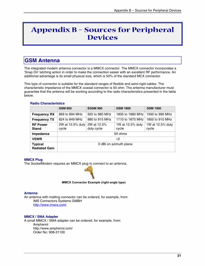
GSM AntennaThe integrated modem antenna connector is a MMCX connector. The MMCX connector incorporates a'Snap On' latching action in order to make the connection easier with an excellent RF performance. Anadditional advantage is its small physical size, which is 50% of the standard MCX connector.
This type of connector is suitable for the standard ranges of flexible and semi-rigid cables. Thecharacteristic impedance of the MMCX coaxial connector is 50 ohm. The antenna manufacturer mustguarantee that the antenna will be working according to the radio characteristics presented in the tablebelow.
Radio CharacteristicsGSM 850 EGSM 900 GSM 1800 GSM 1900
Frequency RX 869 to 894 MHz 925 to 960 MHz 1805 to 1880 MHz 1930 to 990 MHz
Frequency TX 824 to 849 MHz 880 to 915 MHz 1710 to 1875 MHz 1850 to 910 MHz
RF PowerStand
2W at 12.5% dutycycle
2W at 12.5%duty cycle
1W at 12.5% dutycycle
1W at 12.5% dutycycle
Impedance 50 ohms
VSWR <2
TypicalRadiated Gain
0 dBi on azimuth plane
MMCX PlugThe SocketModem requires an MMCX plug to connect to an antenna.
MMCX Connector Example (right angle type)
AntennaAn antenna with matting connector can be ordered, for example, from:
IMS Connectors Systems GMBHhttp://www.imscs.com/
MMCX / SMA AdapterA small MMCX / SMA adapter can be ordered, for example, from:
Amphenolhttp://www.amphenol.com/Order No: 908-31100
Appendix C – AT Commands
22
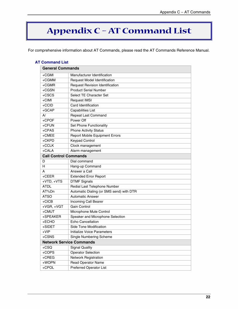
Appendix C – AT Command List
For comprehensive information about AT Commands, please read the AT Commands Reference Manual.
AT Command List
General Commands
+CGMI Manufacturer Identification+CGMM Request Model Identification+CGMR Request Revision Identification+CGSN Product Serial Number+CSCS Select TE Character Set+CIMI Request IMSI+CCID Card Identification+GCAP Capabilities ListA/ Repeat Last Command+CPOF Power Off+CFUN Set Phone Functionality+CPAS Phone Activity Status+CMEE Report Mobile Equipment Errors+CKPD Keypad Control+CCLK Clock management+CALA Alarm management
Call Control CommandsD Dial commandH Hang-up CommandA Answer a Call+CEER Extended Error Report+VTD, +VTS DTMF SignalsATDL Redial Last Telephone NumberAT%Dn Automatic Dialing (or SMS send) with DTRATSO Automatic Answer+CICB Incoming Call Bearer+VGR, +VGT Gain Control+CMUT Microphone Mute Control+SPEAKER Speaker and Microphone Selection+ECHO Echo Cancellation+SIDET Side Tone Modification+VIP Initialize Voice Parameters+CSNS Single Numbering Scheme
Network Service Commands+CSQ Signal Quality+COPS Operator Selection+CREG Network Registration+WOPN Read Operator Name+CPOL Preferred Operator List
Appendix C – AT Commands
23
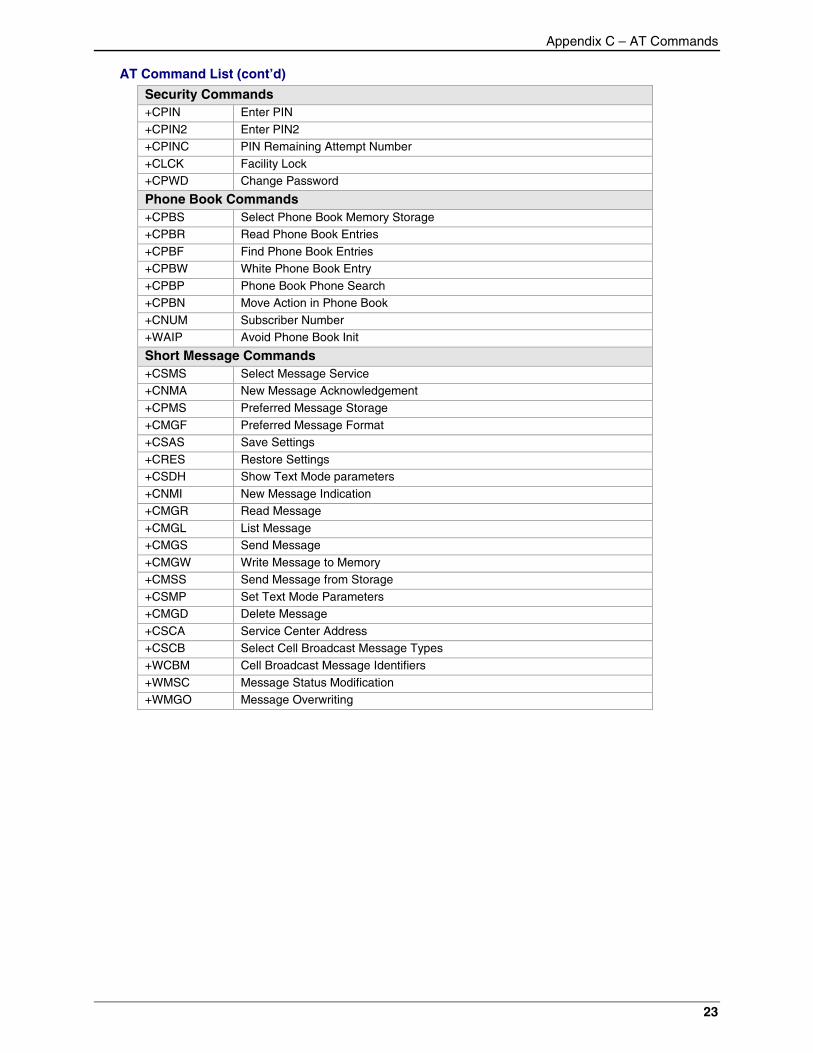
AT Command List (cont’d)
Security Commands+CPIN Enter PIN+CPIN2 Enter PIN2+CPINC PIN Remaining Attempt Number+CLCK Facility Lock+CPWD Change Password
Phone Book Commands+CPBS Select Phone Book Memory Storage+CPBR Read Phone Book Entries+CPBF Find Phone Book Entries+CPBW White Phone Book Entry+CPBP Phone Book Phone Search+CPBN Move Action in Phone Book+CNUM Subscriber Number+WAIP Avoid Phone Book Init
Short Message Commands+CSMS Select Message Service+CNMA New Message Acknowledgement+CPMS Preferred Message Storage+CMGF Preferred Message Format+CSAS Save Settings+CRES Restore Settings+CSDH Show Text Mode parameters+CNMI New Message Indication+CMGR Read Message+CMGL List Message+CMGS Send Message+CMGW Write Message to Memory+CMSS Send Message from Storage+CSMP Set Text Mode Parameters+CMGD Delete Message+CSCA Service Center Address+CSCB Select Cell Broadcast Message Types+WCBM Cell Broadcast Message Identifiers+WMSC Message Status Modification+WMGO Message Overwriting
Appendix C – AT Commands
24
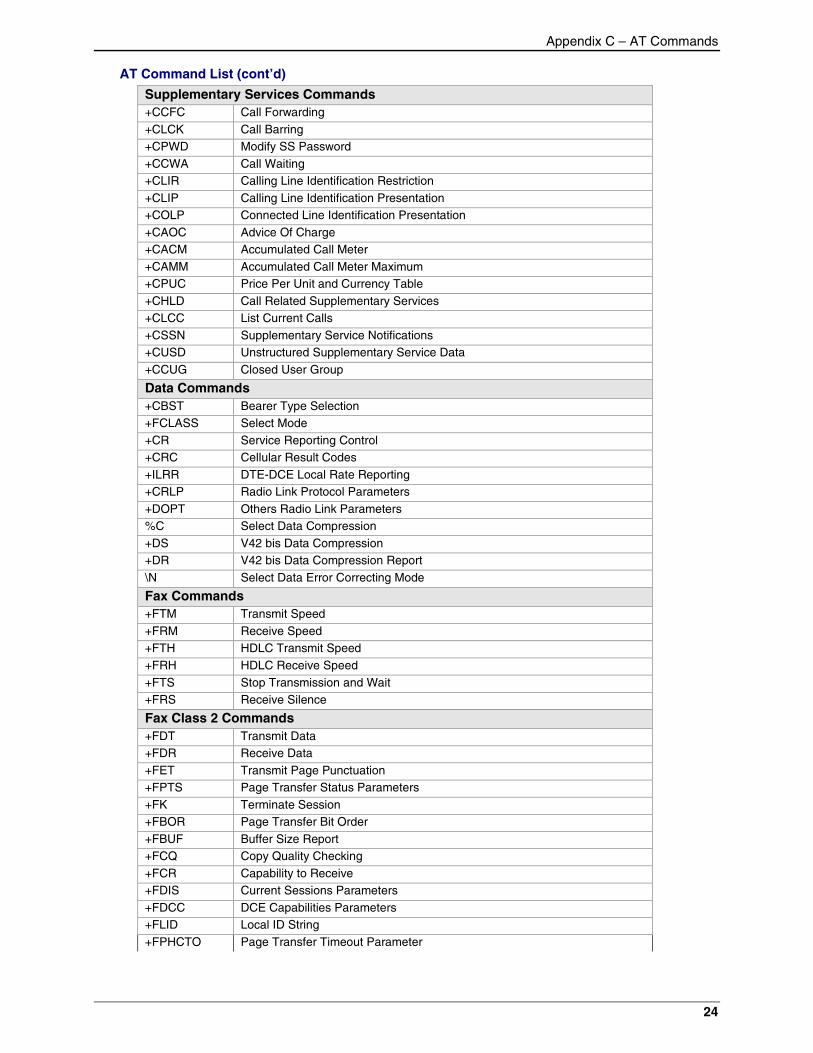
AT Command List (cont’d)
Supplementary Services Commands+CCFC Call Forwarding+CLCK Call Barring+CPWD Modify SS Password+CCWA Call Waiting+CLIR Calling Line Identification Restriction+CLIP Calling Line Identification Presentation+COLP Connected Line Identification Presentation+CAOC Advice Of Charge+CACM Accumulated Call Meter+CAMM Accumulated Call Meter Maximum+CPUC Price Per Unit and Currency Table+CHLD Call Related Supplementary Services+CLCC List Current Calls+CSSN Supplementary Service Notifications+CUSD Unstructured Supplementary Service Data+CCUG Closed User Group
Data Commands+CBST Bearer Type Selection+FCLASS Select Mode+CR Service Reporting Control+CRC Cellular Result Codes+ILRR DTE-DCE Local Rate Reporting+CRLP Radio Link Protocol Parameters+DOPT Others Radio Link Parameters%C Select Data Compression+DS V42 bis Data Compression+DR V42 bis Data Compression Report\N Select Data Error Correcting Mode
Fax Commands+FTM Transmit Speed+FRM Receive Speed+FTH HDLC Transmit Speed+FRH HDLC Receive Speed+FTS Stop Transmission and Wait+FRS Receive Silence
Fax Class 2 Commands+FDT Transmit Data+FDR Receive Data+FET Transmit Page Punctuation+FPTS Page Transfer Status Parameters+FK Terminate Session+FBOR Page Transfer Bit Order+FBUF Buffer Size Report+FCQ Copy Quality Checking+FCR Capability to Receive+FDIS Current Sessions Parameters+FDCC DCE Capabilities Parameters+FLID Local ID String+FPHCTO Page Transfer Timeout Parameter
Appendix C – AT Commands
25
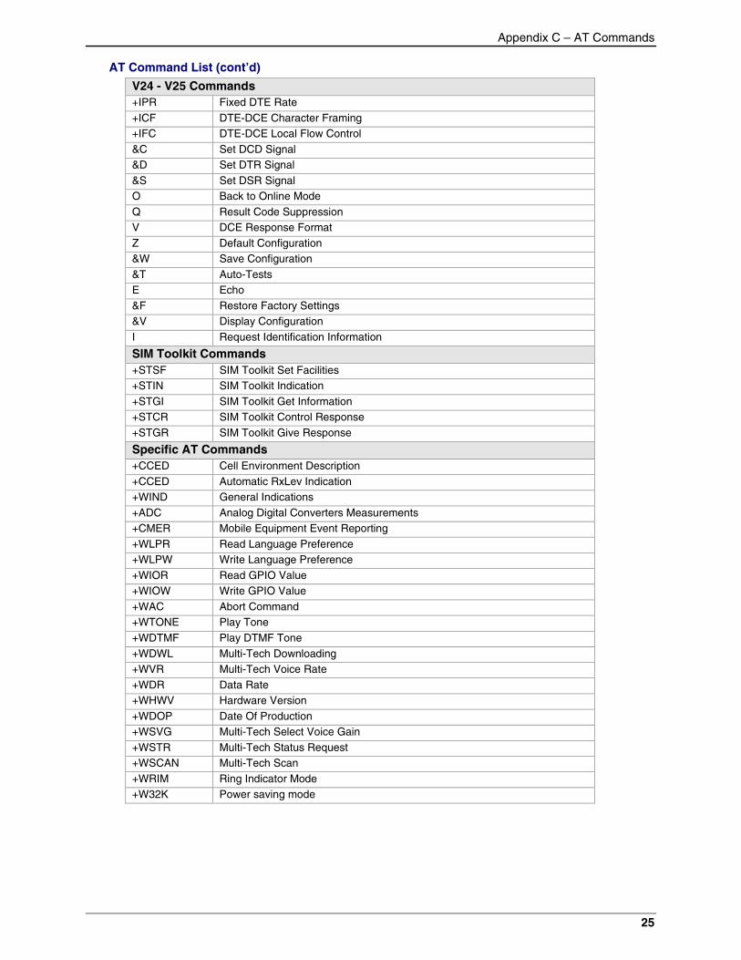
AT Command List (cont’d)
V24 - V25 Commands+IPR Fixed DTE Rate+ICF DTE-DCE Character Framing+IFC DTE-DCE Local Flow Control&C Set DCD Signal&D Set DTR Signal&S Set DSR SignalO Back to Online ModeQ Result Code SuppressionV DCE Response FormatZ Default Configuration&W Save Configuration&T Auto-TestsE Echo&F Restore Factory Settings&V Display ConfigurationI Request Identification Information
SIM Toolkit Commands+STSF SIM Toolkit Set Facilities+STIN SIM Toolkit Indication+STGI SIM Toolkit Get Information+STCR SIM Toolkit Control Response+STGR SIM Toolkit Give Response
Specific AT Commands+CCED Cell Environment Description+CCED Automatic RxLev Indication+WIND General Indications+ADC Analog Digital Converters Measurements+CMER Mobile Equipment Event Reporting+WLPR Read Language Preference+WLPW Write Language Preference+WIOR Read GPIO Value+WIOW Write GPIO Value+WAC Abort Command+WTONE Play Tone+WDTMF Play DTMF Tone+WDWL Multi-Tech Downloading+WVR Multi-Tech Voice Rate+WDR Data Rate+WHWV Hardware Version+WDOP Date Of Production+WSVG Multi-Tech Select Voice Gain+WSTR Multi-Tech Status Request+WSCAN Multi-Tech Scan+WRIM Ring Indicator Mode+W32K Power saving mode
Appendix D – Acronyms and Abbreviations
26
Appendix D – Acronyms andAbbreviations
ADC – Analog Digital ConverterASIC – Application Specific Integrated CircuitBCCH – Broadcast Control ChannelCE – Communauté EuropéenneCLK – ClockCTS – Clear To senddB – decibelDCD – Data Carrier DetectDCE – Data Circuit Terminating EquipmentDSR – Data Set ReadyDTE – Data Terminal EquipmentDTR – Data Terminated ReadyEFR – Enhanced Full RateEGSM – Extended GSMEMC – Electromagnetic ConformityEN – EnableETSI – European Telecommunications Standards InstituteFAC – Final Assembly CodeFR – Full-RateFTA – Full Type ApprovalGND – GroundGPIO – General Purpose Input OutputGPRS – General Packet Radio ServiceGSM – Global System for Mobile CommunicationHR – Half-RateIMEI – International Mobile Equipment IdentityMO – Mobile OriginatedMT – Mobile TerminatedOEM – Original Equipment ManufacturerPDA – Personal Digital AssistantPCB – Printed Circuit BoardPRES – PresenceRI – Ring IndicatorRTS – Request To SendSIM – Subscriber Identity ModuleSMD – Surface Mounted DesignSMS – Short Message ServiceTAC – Type Approval CodeTDMA – Time Code Multiple AccessTE – Terminal EquipmentVSWR – Voltage Standing Wave RatioWAP – Wireless Application Protocol
Index
27
Index
Advice Of Charge, 23aircraft and safety, 17analog, 25antenna, 12, 15, 16, 20antenna cable, 15applications, 4AT command, 6AT commands documentation, 5blasting areas and safety, 17Call Barring, 23Call Forwarding, 23Call Waiting, 23CE, 19, 25Cell Broadcast, 22children and safety, 17Closed User Group, 23connector, 12, 20Data Carrier Detect, 25dB, 12, 25DCS, 12driving safety, 17EFR, 25electronic devices and safety, 17ESD protection, 15ETSI, 12, 25explosive atmospheres and safety, 17firmware upgrad, 15FR, 25gain, 18GND, 25GPIO, 24, 25GPRS, 25GSM, 11, 12, 20, 25
GSM Compliance, 19HR, 25I/O, 11Instructions to OEMs, 18interface, 11medical electronic equipment and safety, 17MMCX (Miniature Micro Connector), 12, 20MO, 25modem, 6, 20MT, 25operating conditions, 18PCB, 25PCS, 12, 18power, 11, 12, 15, 16power supply, 11radio, 16, 20RF, 12, 15, 16, 20RF Exposures, 18safety, 16Safety Standards, 18signal, 11SIM, 10, 11, 24, 25SIM Toolkit, 24SIMCLK, 10, 11SIMDATA, 10, 11SIMRST, 10, 11SIMVCC, 10, 11SMS, 21, 25Specifications
technical, 6Technical specifications, 6vehicle electronic equipment and safety, 17WAP, 25