Embed Size (px)
Citation preview

The ITB Journal The ITB Journal
Volume 7 Issue 1 Article 4
2006
SoC Test: Trends and Recent Standards SoC Test: Trends and Recent Standards
Michael Higgins
Ciaran MacNamee
Follow this and additional works at: https://arrow.tudublin.ie/itbj
Part of the Electrical and Computer Engineering Commons
Recommended Citation Recommended Citation Higgins, Michael and MacNamee, Ciaran (2006) "SoC Test: Trends and Recent Standards," The ITB Journal: Vol. 7: Iss. 1, Article 4. doi:10.21427/D7PN0Z Available at: https://arrow.tudublin.ie/itbj/vol7/iss1/4
This Article is brought to you for free and open access by the Ceased publication at ARROW@TU Dublin. It has been accepted for inclusion in The ITB Journal by an authorized administrator of ARROW@TU Dublin. For more information, please contact [email protected], [email protected].
This work is licensed under a Creative Commons Attribution-Noncommercial-Share Alike 4.0 License

ITB Journal
Issue Number 13, May 2006 Page 24
SoC Test: Trends And Recent Standards.
Michael Higgins and Ciaran MacNamee. Circuits and Systems Research Centre (CSRC),
University of Limerick. Email: [email protected]
Abstract
The well-known approaching test cost crisis, where semiconductor test costs begin to approach or exceed manufacturing costs has led test engineers to apply new solutions to the problem of testing System-On-Chip (SoC) designs containing multiple IP (Intellectual Property) cores. While it is not yet possible to apply generic test architectures to an IP core within a SoC, the emergence of a number of similar approaches, and the release of new industry standards, such as IEEE 1500 and IEEE 1450.6, may begin to change this situation. This paper looks at these standards and at some techniques currently used by SoC test engineers. An extensive reference list is included, reflecting the purpose of this publication as a review paper. 1. INTRODUCTION.
With the recent approval and acceptance of the IEEE 1500 standard for the test of core-based
integrated circuits and the IEEE 1450.6 standard for CTL (core test language), it is an
appropriate time to review what techniques and standards are currently being used by industry
including some that are compatible with these two IEEE standards. Section two of this paper
documents a selection of the different types of ATE (Automated Test Equipment) that are
available and how these ATE approaches are influenced by cost and functionality. Section
three describes some SoC test architectures that have been used by industry in advance of the
publication of the IEEE 1500 standard. TESTRAIL and AMBA focus on TAM (Test Access
Mechanism) development, whereas TESTSHELL and TESTCOLLAR focus on core test
wrapper development. It is also shown how the ETM10 by ARM has had the IEEE 1500
wrapper built around its core. Software tools and test vector compression techniques that have
been used are presented in section four, which include schemes such as IBMs STUMPS,
Philips TR-Architect, SmartBIST and IEEE 1450.6. Section five gives a general overview of
embedded memory test. Embedded memory test is in itself a challenge and some approaches
to its testing are described depicting its significance in the overall SoC test area. The
embedded memory test section includes techniques such as: Fault Modelling, BIST (Built In
Self Test), BISR (Built In Self Repair) and image processing techniques. Section six briefly
outlines examples of how industry has already adopted the IEEE 1500 and IEEE 1450.6
standards.
2. CURRENT ATE APPROACHES. ATE systems can be broadly categorised into three types: Conventional ‘Big Iron’ testers
(typically costs above $1,000,000), ‘Middle Iron’ testers (costs range between $399,000 and
ITB Journal
Issue Number 13, May 2006 Page 25
$1,000,000 [1]), and Low cost DFT focused testers (Teseda’s V500 approximate cost is
$60000 [2]). To understand the role of an ATE it is useful to understand the difference
between structural and functional testing. Structural testing involves developing a set of test
vectors to detect specific faults that may have been introduced in the design by errors such as
DSM (Deep Sub Micron) effects and processing defects. By applying specific test vectors to a
circuit, and then capturing and comparing the actual responses against the expected responses
is what is known as functional testing. ‘Big Iron’ testers are designed to test the device
functionally; at speed functional testing is performed at every pin. An example of a ‘Big Iron’
ATE is the Teradyne Catalyst [3]. ‘Middle Iron’ testers combine structural and functional
testing. Some tradeoffs in speed, performance or flexibility are made with ‘Middle Iron’
testers in comparison to the ‘Big Iron’ testers such that overall ATE cost is reduced. An
example of a ‘Middle Iron’ tester is the Agilent 93000 [4]. Low cost DFT (Design For Test)
focused testers have limited or no functional test capabilities, they are designed to support test
methodologies such as boundary scan or BIST. This type or architecture does not have as high
a level of flexibility and accuracy as the ‘Big Iron’ and ‘Middle Iron’ testers but can have a
lower cost due to its reduced flexibility and accuracy. The software of a DFT focused tester
can play a more pertinent role than the hardware itself. In the case of Teseda’s V500 [5],
IEEE 1450 STIL (Standard Test Interface Language) is used which provides an interface
between digital test generation tools and test equipment.
Multi-site testing is an effective and popular way to increase throughput and reduce the cost
of test [6]. Multi-site testing is described as testing multiple instances of the same SoC in
parallel on a single ATE. In addition to the reduction of test cost by multi-site testing it has
also been noted that increasing the vector memory depth is more cost effective than increasing
the number of ATE channels [6]. The Tiger test system by Teradyne takes advantage of the
benefits of multi-site testing by incorporating multi-site test for complex devices. The
economic advantages of combining multi-site testing with reduced pin-count test, low channel
cost ATE and bandwidth matching are explored by [7] where it is found that the multi-site test
approach had more benefits than the single-site test approach.
A method is described by [8] where ATE and EDA (Electronic Design Automation) tools are
linked to identify and diagnose failures at layout level. In this approach the ATE and EDA
tools share the EDA IC design database and ATE failure datalog to determine a failure and
then identify the location and cause of the failure.
STEPS (Software-based Test Environment for P1500 compliant SoCs) [9] is based on the
concept that the ATE is not considered as an initiator applying vectors to SoC test pins but a
target comprising of a bank of 32 bit test data and control commands. Using STEPS the SoC
ITB Journal
Issue Number 13, May 2006 Page 26
can act as the active component and the ATE as the passive component. STEPS has the
advantage that the test program is executed at the system speed and is not limited by the ATE
frequency.
3. SOC TEST ARCHITECTURES. a) IEEE 1500
The IEEE 1500 standard was approved in late March 2005 after the IEEE P1500 SECT was
started ten years earlier in 1995. The scope of the standard defines a mechanism for the test of
core designs within a SoC. This mechanism constitutes a hardware architecture and leverages
the CTL to facilitate communication between core designers and core integrators [10]. The
IEEE 1500 has two levels of compliance: a wrapped and unwrapped compliance. The
wrapped compliance caters for a core that comes with an IEEE 1500 wrapper function and a
CTL program. The unwrapped compliance refers to a core that does not have an (complete)
IEEE 1500 wrapper but does have a CTL description. The IEEE 1500 is independent of the
functionality of the IC or the embedded cores. The IEEE 1500 is a new standard, but it has
been widely anticipated and discussed for a number of years, so this paper attempts to look at
some other industrial SoC test techniques and attempts to outline their levels of compatibility
with the IEEE 1500.
b) Philips TESTRAIL
The scalable and flexible TAM TESTRAIL developed by Philips can provide access to one or
more cores. A SoC may contain more than one TESTRAIL each of varying bandwidth
determined by the width of the TESTRAIL [11]. The TESTRAIL approach attempts to
combine both the strengths of TESTBUS and BST (Boundary Scan Test) [12]. BST is the
IEEE 1149.1 standard for test access port and boundary scan architecture. The TESTBUS
architecture allows the cores under test to be directly accessed from the pins of the IC. The
TESTBUS approach can have one or more TESTBUSs per SoC similar to TESTRAIL so that
tradeoffs can be made between silicon area and test time [12]. Similar to BST, multiple cores
can be daisy-chained into one TESTRAIL. The TESTRAIL architecture is therefore a
combination of daisychain and distribution architectures. A daisychain architecture can be
achieved using only one TESTRAIL, whereas a distribution architecture can be implemented
using more than one TESTRAIL where each TESTRAIL acts independently [13]. A
TESTRAIL example is shown in figure 1. Core A has a private TESTRAIL of 16 bits, while
the TESTRAILs both 16 bits of core B and C is concatenated. The two TESTRAILs from
core A and from core B and C are then multiplexed back onto one single 16-bit TESTRAIL.
Figure 1 is an example of the flexibility of TESTRAIL.

ITB Journal
Issue Number 13, May 2006 Page 27
Figure 6: TESTRAIL Example Architecture [11, 14]
c) TESTSHELL & TESTCOLLAR
Other hardware approaches that have been used to test SoCs are TESTSHELL [14] and
TESTCOLLAR [15]. These two approaches are considered similar to the recently approved
IEEE 1500 due to the scalability of their TAMs [12]. A TESTSHELL example used in
conjunction with TESTRAIL is shown in figure 2. TESTSHELL is an interface layer between
the piece of IP (Intellectual Property) and the host environment. This interface layer wraps the
piece of IP and has four modes of operation: function, IP test, interconnect test and bypass
[14].
Figure 7: TESTSHELL used with TESTRAIL[12]
TESTCOLLAR cells are added to pieces of IP for the primary purpose of isolation; isolating
the IP from the rest of the system to enable test or isolating the UDL (User Defined Logic)
from the rest of the system so that it and its interconnects can be tested [15]. The structure of
the TESTCOLLAR cell is shown in figure 3. There are three basic types of TESTCOLLAR
Core A
Core B
Core C
16
16
16
16 16
16 16
Core C
TESTSHELL TESTSHELL TESTSHELL
TESTRAIL
Core B Core A
Core A
Core B Core C
16
16
16
16 16
16 16
ITB Journal
Issue Number 13, May 2006 Page 28
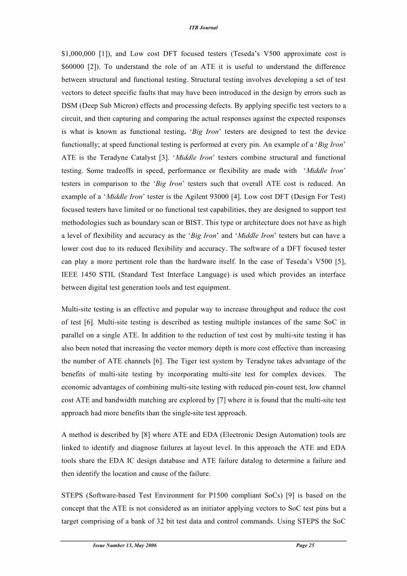
cells: combinational, latched and registered. Full implementation of TESTCOLLAR at the
input and output of each component provides a double level test structure. Providing a “full
featured” TESTCOLLAR around each component can result in a double-level test structure,
i.e. observability and controllability. This double level test structure can lead to a higher cost
for the test structure implementation [15].
Figure 8: TESTCOLLAR [15]
d) ARM (Advanced RISC Machines)
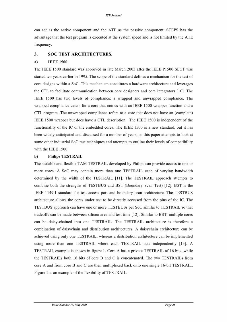
Given that many SoC test applications require access to individual cores as well as the
isolation of these cores, it would appear that the SoCs functional bus structure might be used
to realise a workable TAM. Some test applications of the well-known AMBA (Advanced
Micro-controller Bus Architecture) bus structure attempt to do this. An example [12] of
ARM’s AMBA system is shown in figure 4. 32 bit test vectors are passed from the IC pins to
the core under test using the EBI (External Bus Interface).
Figure 9: ARMs AMBA System [12]
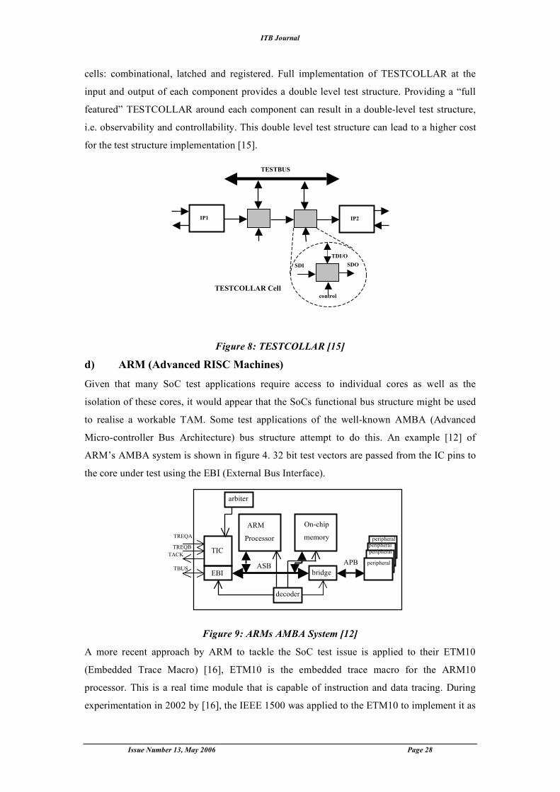
A more recent approach by ARM to tackle the SoC test issue is applied to their ETM10
(Embedded Trace Macro) [16], ETM10 is the embedded trace macro for the ARM10
processor. This is a real time module that is capable of instruction and data tracing. During
experimentation in 2002 by [16], the IEEE 1500 was applied to the ETM10 to implement it as
IP1 IP2
TESTCOLLAR Cell
TESTBUS
SDI SDO TDI/O
control
ARM
Processor
On-chip
memory
bridge
decoder
arbiter
TIC
EBI ASB APB peripheral
peripheral
peripheral peripheral
TREQA
TREQB TACK
TBUS
ITB Journal
Issue Number 13, May 2006 Page 29
a full scan core. Figure 5 shows how the IEEE 1500 wrapper was built around the ETM10. A
two-step approach was used to check the functionality of the IEEE 1500 wrapper. Firstly, test
patterns were generated using an ATPG tool and then verified with a Verilog test-bench on
the ETM10 without the WIR or WBY. Secondly the same patterns were applied with the WIR
and WBY included in the design with the ETM10. The ETM10s test coverage was the same
in each instance, showing that the IEEE 1500 test wrapper can be used without any
degradation in test coverage.
Figure 10: ETM10 with IEEE 1500 Wrapper [16]
4. SOFTWARE TOOLS AND TEST VECTOR COMPRESSION
Functional testing represented the first generation (1G) of IC test. The shift from functional
test to scan test represented the second generation (2G). The multimillion gate SOC provides
new challenges for the third generation (3G) of digital test [17].
Two critical challenges that test planning for SOC must address are: Handling the increase in
test suite sizes (“can we fit a new test suite on an existing ATE?”) and transporting test data to
cores embedded deep within the system (“Can we get test data to where we want it on chip
and can we do it on time?”) [18]. The pin count is one of the main causes of speed
degradation for test data transfer across the chip [19]. To reduce the number of test pins and
memory size required for ATE, the test data that is transferred between the ATE and the SOC
needs to be reduced. To reduce the test data, compaction and loss-less compression schemes
can be used. The techniques that can be used in these compaction and compression schemes
can be divided into three categories [20]:Vertical Compression (minimize the amount of test
data per ATE pin), Horizontal Compression (reduce the number of ATE channels) and
schemes that incorporate both vertical and horizontal compression. Horizontal compression
ETM10 CORE
W
B
R
WBY
0 1
0
1
1 0
WIR
WCLK
WSI
WSI
WBYPAS S
SelectWIR
WRSTN
UpdateWR
ShiftW R
Capture WR

ITB Journal
Issue Number 13, May 2006 Page 30
can be achieved by serialising the test data. Data could be loaded serially using only one test
pin but this requires an increased memory depth and longer test time [20].
TAM design and test data compression offer promising solutions to the problem of ballooning
test data volume, more complex ATE requirements and the challenge of transporting test data
to the cores. In work conducted by [18] the use of data compression and TAM design is
presented as an integrated approach to modular SoC test.
a) IBMs STUMPS
On-Product signature generation techniques are well known from Logic BIST. IBM’s
pioneering scan-based logic BIST is called STUMPS (Self Test Using a MISR (Multiple
Input Signature Register) and Parallel SRSG (Shift Register Sequence Generator)), which
uses a MISR at the outputs of product scan chains [21]. The OPMISR (On-Product MISR)
solution intends to reduce the required number of ATE pins as well as the amount of test
responses to send back to the ATE. Initially, the input and output circuit ports are merged into
bi-directional ports. Additionally, an MISR is inserted on scan chain outputs. The scan vector
signatures (compacted responses) are transmitted back to the ATE trough I/O ports instead of
bit-by-bit responses [20].
b) SmartBIST
SmartBIST [22] is the name for a family of streaming scan test pattern decoders that are
suitable for on-chip integration. SmartBIST is the second phase of a technology roadmap that
combines the benefits of ATPG (Automatic Test Pattern Generation) and Logic BIST
techniques for the cost effective testing of 100M+ gate chips. The first phase, called On-
Product MISR or OPMISR, has already been implemented in the DFT and ATPG tools for
selective use on very large ASIC chips. The use of an OPMISR essentially eliminates most of
the data volume and solves some of the logic test throughput issues related to the test response
data. SmartBIST is intended for very large and complex designs.
c) Linear Compression Schemes
Test vector compression schemes, as described by [23], that use only linear operations to
decompress the test vectors are called linear decompression schemes. Linear decompression
techniques exploit the unspecified (don’t care) bit positions in scan test cubes (i.e.
deterministic scan test vectors where the unassigned bit positions are left as don’t cares) to
achieve large amount of compression. Continuous flow linear decompressors are those that
receive data from the tester in a continuous-flow manner i.e. every cycle. These operate very
efficiently since they can be directly connected to the tester and they simply receive the data
as fast as the tester can transfer it.

ITB Journal
Issue Number 13, May 2006 Page 31
d) Philips TR-Architect The TR-Architect tool has been developed by Philips, which is designed to generate a test
architecture for SoCs that are more complex than just a handful of cores. (In the case of a SoC
with relatively few cores, it may be simpler to develop the test architecture manually.) TR-
Architect accepts two inputs: a SoC data file and a list of user options. The SoC data file
consists of information about the SoC itself such as: the numbers of modules embedded in the
SoC, the number of inputs, outputs, bi-directionals, test patterns and the number of scan
chains and their lengths [24]. The user options list contains more information about the SoC
and its properties. These can be categorised as follows: Total number of SoC test pins, Types
of modules (hard/soft), External bypass per module, Test schedule type (serial/parallel), TAM
type (test bus/test rail), Architecture type and Test cost [24]. The TR-Architect tool supports
three types of architectures: Daisychain, Distributed and a Hybrid of the previous two as
shown in figure 6.
Figure 11: (a) Daisychain, (b) Distribution, (c) Hybrid [24]
e) IEEE 1450.6 CTL
The IEEE 1450.6 standard for Standard Test Interface Language (STIL) for digital test vector
data – Core Test Language (CTL) has recently been approved. IEEE 1450.6 describes CTL,
which has a close connection with the recently published IEEE 1500 standard for embedded
core based test. CTL is a language for capturing and expressing test-related information
for reusable cores, which is meant to co-exist with and complement information
expressed as a netlist. CTL is an extension of IEEE 1450 STIL and is a software language
that is targeted to SoC DFT. IEEE 1450.6 is used to describe IEEE 1500 wrappers. An
appropriate TAM and wrapper can be designed using the CTL description of a core. The
system integrator can test an embedded core and UDL around a core in a SoC using
information that is supplied by the CTL description of the core provided by the designer.
The bulk of the data in CTL is reusable without modification by using protocol
statements from the traditional STIL. CTL is machine and human readable therefore
allowing the CTL program to be used for documentation processes. This language is broad
enough to describe 1500, VSIA (Virtual Socket Interface Alliance) and even IEEE 1149.1
Core A
Core B
Core C
Core A
Core B
Core C
Core A
Core B
Core C
SoC SoC SoC
(a) (b) (c)
IN
IN
IN
IN
IN
IN
OUT
OUT
OUT
OUT
OUT
OUT

ITB Journal
Issue Number 13, May 2006 Page 32
[25]. It has been speculated by [26] that the IEEE 1450.6 could result in new and more
powerful test optimisation capability and it has been noted that some IEEE 1450.6 tools have
become available.
5. EMBEDDED MEMORY TEST
The ITRS (International Technology Roadmap for Semiconductors) 2001 speculates that
embedded memories will dominate the majority of silicon area of a SoC (approximately 94%)
by the year 2014. If this trend is to continue it is likely that embedded memory yield will
worsen. The cost of memory testing increases with every new generation of memory chips
[27]. Embedded memories have several advantages that include: improved performance,
lower power consumption and overall cost. These advantages do have complications such as
yield limitations, higher mask cost and an increased development complexity. Some of the
strategies that are used to test embedded memories are introduced below.
a) Fault Modelling
Fault modelling is the translation of physical defects to a mathematical construct that can be
operated upon algorithmically and understood by a software simulator to provide a quality
measurement. One of the most common fault models is the Stuck At Fault (SAF) but there are
many more. Static faults such as SAF and address decoder faults are sensitised by applying at
most one operation. Dynamic faults take place in the absence of static faults, which require
more than one operation to be performed sequentially in time so that they are sensitised. The
majority of tests used in industry target specific faults and therefore may not detect dynamic
faults [28].
b) BIST
BIST is considered to be one of the most cost effective solutions for embedded memory test
[29]. The philosophy behind BIST is to let the hardware test itself. Although BIST is
considered to be one of the more cost effective methods to test embedded memory, it will face
challenges including: minimising the BIST overhead in both silicon area and routing,
adhering to power budget constraints and support of different types of memory [28]. A new
MBIST (Memory BIST) architecture is described by [30] which attempts to address some of
the above challenges. PBIST (Programmable BIST) is described by [31] that targets specific
faults in memory according to the user defined algorithm used. It is suggested by [32] that it is
possible to programme the BIST circuit using an on-chip microprocessor that almost any SoC
has incorporated into its design. This on-chip processor core can also be used to test other
cores on the same chip.
c) BISR
BISR is used to enhance memory yield. Depending on redundancy and the BISR method used
it is possible to increase yield by between 5% and 20% [33]. Repair is essential for present

ITB Journal
Issue Number 13, May 2006 Page 33
and future memory technologies. The traditional way to perform memory repair is usually
external test and repair. All known repair algorithms are not optimal and future schemes must
consider practical issues including [28]: low hardware cost, test time reduction and ‘on the
fly’ repair.
d) Hough Transform
Another strategy that has been investigated by [34] for the diagnosis of faults in embedded
memories, is the use of an image processing technique; the Hough transform. The Hough
transform is used to identify the most probable failure pattern among the set of possible ones
provided in a fault dictionary.
6. INDUSTRY ADOPTION OF CURRENT STANDARDS AND TEST
STRATEGIES.
Three examples of tools incorporating the new test strategies are described below.
The DFT compiler, SoCBIST by Synopsys [35] automates the creation and integration of IP
cores, optimised for test reuse. This tool is based on the IEEE 1450.6 standard. First, the DFT
Compiler automatically synthesizes test-reuse IP cores and creates CTL test models for them.
Synopsys' TetraMAX automatic test-pattern generation tool then creates reusable test patterns
for those cores. Finally, the SoCBIST tool reads the CTL models of these cores and
automatically integrates the cores into the overall SoC, reusing pre-supplied core test patterns
referenced from the SoC-level pattern set.[36]
Logic Vision has developed a test architecture for cores that are embedded within a SoC
called ELT (Embedded Logic Test) Core. ELT core operates by placing an ELT controller in
each logic block in the system. Each of these controllers supports random pattern testing and
external scan test. Each of the logic blocks within the system can be isolated using the ELT
controllers for multi-clock domain, at-speed testing. One of the isolation approaches,
dedicated isolation, supports the requirements of the IEEE 1500 standard for test ready cores.
Access to the ELT controllers is provided through a hierarchical TAP architecture compliant
with the IEEE 1500 standard. One of the advantages of using this IEEE 1500 standard
compliant approach is reduced global test signal routing [37].
The Standard for Embedded Core Test (SECT) eVC (Verification Components) by Globetech
Solutions [38] can verify a chain of one or more IEEE 1500 compliant core wrappers. The
eVCs are fully compliant with the IEEE 1500. The SECT eVC will also provide a feature in
the future that will support CTL based auto configuration.
7. CONCLUSION.
In this paper, we have looked at a number of important new techniques, which have been used
to test multi-core System-on-Chip designs. It is particularly useful to observe how some of
the analyses and proposals of the last decade or so have come to fruition in the form of
ITB Journal
Issue Number 13, May 2006 Page 34
implementation of some practical solutions. Many of these solutions are similar to or
compatible with the proposals outlined in the recently adopted IEEE standards 1500 and
1450.6. In addition we have noted the release of some tools that incorporate elements of these
standards. These developments mean that the next few years will allow researchers to make a
realistic assessment of how well their efforts have succeeded in making real progress in
overcoming the many challenges of System-on-Chip testing.
8. ACKNOWLEDGEMENT
The authors acknowledge the support of the CSRC at the University of Limerick.
9. REFERENCES [1] Electronic_Design, "Penny-A-Second SoC DFT Tester Saves Time," 2003. [2] http://www.ikonix.com/, "The Final Test Report (FTR)," vol. 14, pp. 12, 2003. [3] Teradyne, "http://www.teradyne.com/catalyst/," ND. [4] Agilent, "http://www.home.agilent.com/USeng/nav/-536886626.0/pc.html," ND. [5] www.teseda.com/pdfs, "Transporting STIL between the Teseda V500 and the Agilent 93000 SOC
Tester," 2004. [6] S. K. Goel and E. J. Marinissen, "On-chip test infrastructure design for optimal multi-site testing of
system chips," presented at Design, Automation and Test in Europe, 2005. Proceedings, 2005. [7] E. H. Volkerink, A. Khoche, J. Rivoir, and K. D. Hilliges, "Test economics for multi-site test with
modern cost reduction techniques," presented at VLSI Test Symposium, 2002. (VTS 2002). Proceedings 20th IEEE, 2002.
[8] K. Nagano, "CAD navigation and diagnostics by linking ATE and EDA," Instrumentation and Measurement, IEEE Transactions on, vol. 54, pp. 1699-1707, 2005.
[9] M. Benabdenbi, A. Greiner, F. Pecheux, E. Viaud, and M. Tuna, "STEPS: experimenting a new software-based strategy for testing SoCs containing P1500-compliant IP cores," presented at Design, Automation and Test in Europe Conference and Exhibition, 2004. Proceedings, 2004.
[10] IEEE, "IEEE Standard Testability Method for Embedded Core-based Integrated Circuits," in IEEE Std 1500-2005, 2005, pp. 0_1-117.
[11] K. Chakrabarty, "Design of system-on-a-chip test access architectures using integer linear programming," presented at VLSI Test Symposium, 2000. Proceedings. 18th IEEE, 2000.
[12] Y. Zorian, E. J. Marinissen, and S. Dey, "Testing embedded-core based system chips," presented at Test Conference, 1998. Proceedings. International, 1998.
[13] S. K. Goel and E. J. Marinissen, "A novel test time reduction algorithm for test architecture design for core-based system chips," presented at European Test Workshop, 2002. Proceedings. The Seventh IEEE, 2002.
[14] E. J. Marinissen, R. Arendsen, G. Bos, H. Dingemanse, M. Lousberg, and C. Wouters, "A structured and scalable mechanism for test access to embedded reusable cores," presented at Test Conference, 1998. Proceedings. International, 1998.
[15] P. Varma and B. Bhatia, "A structured test re-use methodology for core-based system chips," presented at Test Conference, 1998. Proceedings. International, 1998.
[16] T. McLaurin and S. Ghosh, "ETM10 incorporates hardware segment of IEEE P1500," Design & Test of Computers, IEEE, vol. 19, pp. 6-11, 2002.
[17] M. Chandramouli, "DBIST answers advanced SoC test challenges," http://www.synopsys.com,ND. [18] V. Iyengar, A. Chandra, S. Schweizer, and K. Chakrabarty, "A unified approach for SoC testing
using test data compression and TAM optimization," presented at Design, Automation and Test in Europe Conference and Exhibition, 2003, 2003.
[19] F. Karimi, Z. Navabi, W. M. Meleis, and F. Lombardi, "Using data compression in automatic test equipment for system-on-chip testing," Instrumentation and Measurement, IEEE Transactions on, vol. 53, pp. 308-317, 2004.
[20] M.-L. Flottes, R. Poirier, and B. Rouzeyre, "On using test vector differences for reducing test pin numbers," presented at Electronic Design, Test and Applications, 2004. DELTA 2004. Second IEEE International Workshop on, 2004.
[21] C. Barnhart, V. Brunkhorst, F. Distler, O. Farnsworth, B. Keller, and B. Koenemann, "OPMISR: the foundation for compressed ATPG vectors," presented at Test Conference, 2001. Proceedings. International, 2001.

ITB Journal
Issue Number 13, May 2006 Page 35
[22] B. Koenemann, C. Barnhart, B. Keller, T. Snethen, O. Farnsworth, and D. Wheater, "A SmartBIST variant with guaranteed encoding," presented at Test Symposium, 2001. Proceedings. 10th Asian, 2001.
[23] K. J. Balakrishnan and N. A. Touba, "Reconfigurable linear decompressors using symbolic Gaussian elimination," presented at Design, Automation and Test in Europe, 2005. Proceedings, 2005.
[24] S. K. Goel, K. Chiu, E. J. Marinissen, T. Nguyen, and S. Oostdijk, "Test infrastructure design for the Nexperia/spl trade/ home platform PNX8550 system chip," presented at Design, Automation and Test in Europe Conference and Exhibition, 2004. Proceedings, 2004.
[25] R. Kapur, M. Lousberg, T. Taylor, B. Keller, P. Reuter, and D. Kay, "CTL the language for describing core-based test," presented at Test Conference, 2001. Proceedings. International, 2001.
[26] K. R. Miller, W. J. Lonowski, R. Kapur, P. Harrod, and D. Appello, "CTL: The New Language of DFT," in Evaluation Engineering, 2003.
[27] S. Shoukourian, V. Vardanian, and Y. Zorian, "SoC yield optimization via an embedded-memory test and repair infrastructure," Design & Test of Computers, IEEE, vol. 21, pp. 200-207, 2004.
[28] S. Hamdioui, G. Gaydadjiev, and A. J. van de Goor, "The state-of-art and future trends in testing embedded memories," presented at Memory Technology, Design and Testing, 2004. Records of the 2004 International Workshop on, 2004.
[29] S. Banerjee, D. Mukhopadhyay, and D. R. Chowdhury, "Automatic generated built-in-self-test for embedded memory," presented at India Annual Conference, 2004. Proceedings of the IEEE INDICON 2004. First, 2004.
[30] B. H. Fang, Q. Xu, and N. Nicolici, "Hardware/software co-testing of embedded memories in complex SOCs," presented at Computer Aided Design, 2003. ICCAD-2003. International Conference on, 2003.
[31] F. Karimi and F. Lombardi, "A scan-BIST environment for testing embedded memories," presented at Memory Technology, Design and Testing, 2002. (MTDT 2002). Proceedings of the 2002 IEEE International Workshop on, 2002.
[32] C.-H. Tsai and C.-W. Wu, "Processor-programmable memory BIST for bus-connected embedded memories," presented at Design Automation Conference, 2001. Proceedings of the ASP-DAC 2001. Asia and South Pacific, 2001.
[33] R. Rajsuman, System-on-a-Chip: Design and Test. Boston, London: Artech House Publishers, 2000.
[34] D. Appello, A. Fudoli, V. Tancorre, F. Corno, M. Rebaudengo, and M. Sonza Reorda, "A BIST-based solution for the diagnosis of embedded memories adopting image processing techniques," presented at On-Line Testing Workshop, 2002. Proceedings of the Eighth IEEE International, 2002.
[35] Synopsys, "DFT Compiler SoCBIST- Deterministic Logic BIST," 2002. [36] Electronic_Design, "Standards Boost SoC Test," 2003. [37] LogicVision, "Core Embedded Logic Test (ELT Core)," 2004. [38] Globetech_Solutions, "IEEE 1500 (SECT) eVC," 2005.